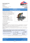
1
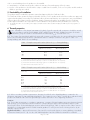
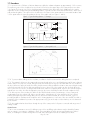
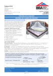
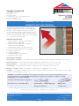
APPROVAL
INSPECTION
TESTING
CERTIFICATION
Superglass Insulation Ltd
Thistle Industrial Estate
Kerse Road
Stirling FK7 7QQ
Tel: 01786 451170 Fax: 01786 451245
TECHNICAL APPROVALS FOR CONSTRUCTION
Agrément Certificate
12/4938
e-mail: [email protected]
website: www.superglass.co.uk
Product Sheet 1
SUPERGLASS CAVITY WALL INSULATION
SUPERWHITE CAVITY WALL INSULATION
This Agrément Certificate Product Sheet(1) relates to
Superwhite Cavity Wall Insulation, a granulated glass
mineral wool fibre material injected in loose form,
for use in masonry walls up to and including 12 m in
height, with nominal cavity widths not less than 50 mm,
in new and existing domestic and non-domestic buildings.
(1) Hereinafter referred to as ‘Certificate’.
CERTIFICATION INCLUDES:
• factors relating to compliance with Building
Regulations where applicable
• factors relating to additional non-regulatory
information where applicable
• independently verified technical specification
• assessment criteria and technical investigations
• design considerations
• installation guidance
• regular surveillance of production
• formal three-yearly review.
KEY FACTORS ASSESSED
Practicability of installation — the product must only be installed by trained and approved installers (see section 5).
Thermal properties — the product has a thermal conductivity of 0.040 W·m–1·K–1 (see section 6).
Water penetration — the product will resist the transfer of water across the cavity (see section 7).
Condensation — the product will contribute to limiting the risk of condensation (see section 8).
Behaviour in relation to fire — the product is classified as non-combustible (see section 9).
Durability — the product is durable, rot-proof, water resistant and sufficiently stable to remain effective as an insulation
for the life of the building (see section 11).
The BBA has awarded this Certificate to the company named above for the product described herein. This
product has been assessed by the BBA as being fit for its intended use provided it is installed, used and
maintained as set out in this Certificate.
On behalf of the British Board of Agrément
Date of First issue: 26 October 2012
Sean Moriarty — Head of Approvals
Greg Cooper
Energy and Ventilation
Chief Executive
The BBA is a UKAS accredited certification body — Number 113. The schedule of the current scope of accreditation for product certification is
available in pdf format via the UKAS link on the BBA website at www.bbacerts.co.uk
Readers are advised to check the validity and latest issue number of this Agrément Certificate by either referring to the BBA website or contacting the BBA direct.
British Board of Agrément
Bucknalls Lane
Watford
Herts WD25 9BA
©2012
Page 1 of 10
tel: 01923 665300
fax: 01923 665301
e-mail: [email protected]
website: www.bbacerts.co.uk
Regulations
In the opinion of the BBA, Superwhite Cavity Wall Insulation, if installed, used and maintained in accordance with
this Certificate, will meet or contribute to meeting the relevant requirements of the following Building Regulations (the
presence of a UK map indicates that the subject is related to the Building Regulations in the region or regions of the
UK depicted):
The Building Regulations 2010 (England and Wales)
Requirement: B3(4)
Internal fire spread (structure)
Comment:
The product is classified as non-combustible and therefore meets this Requirement, and may be used in
buildings of any purpose group. See sections 9.2 and 9.3 of this Certificate.
Requirement: C2(a)
Resistance to moisture
Comment:
The product does not absorb water by capillary action and may therefore be used in situations where it
bridges the damp-proof course (dpc) of the inner and outer leaves. See section 7.1 of this Certificate.
Requirement: C2(b)
Resistance to moisture
Comment:
The product can resist rain penetration and will contribute to a wall satisfying this Requirement. See
sections 4.5, 7.1 and 7.2 of this Certificate.
Requirement: C2(c)
Resistance to moisture
Comment:
The product can contribute to satisfying the Condensation Requirement. See sections 8.1 and 8.3 of this
Certificate.
Requirement: L1(a)(i)
Conservation of fuel and power
Comment:
Requirement: Regulation 7
Materials and workmanship
Comment:
The product is an acceptable material. See section 11.1 and the Installation part of this Certificate.
The product can meet or contribute to meeting this Requirement. See section 6 of this Certificate.
The Building (Scotland) Regulations 2004 (as amended)
Regulation:
8(1)
Regulation:
Standard:
9
2.4
2.6
3.4
3.10
3.15
6.1(b)
6.2
7.1(a)(b)
Comment:
Statement of sustainability
The product can contribute to meeting the relevant requirements of Regulation 9, Standards 1 to 6, and
therefore will contribute to a construction meeting a bronze level of sustainability as defined in this Standard.
In addition the product can contribute to a construction meeting a higher level of sustainability as defined
in this Standard, with reference to clauses 7.1.4(1)(2) Aspects 1(1)(2) and 2(1), 7.1.6(1)(2) Aspects 1(1)(2) and 2(1)
and 7.1.7(1)(2) Aspect 1(1)(2). See section 6 of this Certificate.
Comment:
Regulation:
Carbon dioxide emissions
Building insulation envelope
This product can contribute to satisfying all or parts of clauses 6.1.6(1), 6.2.1(1)(2), 6.2.3(1), 6.2.4(2),
6.2.5(2), 6.2.6(1), 6.2.7(1), 6.2.8(1)(2), 6.2.9(1)(2), 6.2.10(1)(2), 6.2.11(1)(2), 6.2.12(2) and 6.2.13(1)(2) of these
Standards. See section 6 of this Certificate.
Comment:
Standard:
Condensation
The product can satisfy, or contribute to satisfying, this Standard, with reference to clauses 3.15.1(1)(2),
3.15.4(1)(2) and 3.15.5(1)(2). See sections 8.2 and 8.3 of this Certificate.
Comment:
Standard:
Standard:
Precipitation
The product will resist water transfer and may contribute to a wall satisfying clause 3.10.1(1) of this
Standard, provided it complies with the conditions set out in sections 4.5, 7.1 and 7.2 of this Certificate.
Comment:
Standard:
Moisture from the ground
The product can contribute to a construction satisfying this Standard, with reference to clause 3.4.1(1)(2).
The product can be used in situations where it bridges the dpc of the inner and outer leaves. See section
7.1 of this Certificate.
Comment:
Standard:
Spread to neighbouring buildings
The product is classified as non-combustible and may be used in domestic and non-domestic buildings,
with reference to clauses 2.6.5(1) and 2.6.6(2). See sections 9.2, 9.3 and 9.5 of this Certificate.
Comment:
Standard:
Building standards — construction
Cavities
Cavity barriers are not required provided all of the cavity is filled, with reference to clauses 2.4.1(1)(2) and
2.4.2(1). See section 9.5 of this Certificate.
Comment:
Standard:
Fitness and durability of materials and workmanship
The product can contribute to a construction satisfying this Regulation. See section 11.1 and the Installation
part of this Certificate.
Comment:
12
Building standards — conversions
All comments given for this product under Regulation 9, Standards 1 to 6 also apply to this Regulation,
with reference to clause 0.12.1(1)(2) and Schedule 6(1)(2).
(1) Technical Handbook (Domestic).
(2) Technical Handbook (Non-Domestic).
Page 2 of 10
The Building Regulations (Northern Ireland) 2000 (as amended)
Regulation:
B2
Fitness of materials and workmanship
Comment:
Regulation:
C4(a)
Resistance to ground moisture and weather
The product is an acceptable material. See section 11.1 and the Installation part of this Certificate.
The product does not absorb water by capillary action and, therefore, may be used in situations where it
bridges the dpc of the inner and outer leaves. See section 7.1 of this Certificate.
Comment:
Regulation:
C4(b)
Resistance to ground moisture and weather
Walls incorporating the product can satisfy this Regulation. See sections 4.5, 7.1 and 7.2 of this
Certificate.
Comment:
Regulation:
C5
Condensation
Comment:
Regulation:
E4(4)
Internal fire spread — Structure
The product will contribute to meeting this Regulation. See section 8.3 of this Certificate.
The product is classified as non-combustible and may be used in buildings of any purpose group. See
sections 9.2 and 9.3 of this Certificate.
Comment:
Regulation:
Regulation:
F2(a)(i)
F3(2)
Comment:
Conservation measures
Target carbon dioxide Emissions Rate
The product can contribute to satisfying these Regulations. See section 6 of this Certificate.
Construction (Design and Management) Regulations 2007
Construction (Design and Management) Regulations (Northern Ireland) 2007
Information in this Certificate may assist the client, CDM co-ordinator, designer and contractors to address their
obligations under these Regulations.
See sections:
3 Delivery and site handling (3.1 and 3.3) and 13 Site preparation (13.2) of this Certificate.
Additional Information
NHBC Standards 2011
NHBC accepts the use of Superwhite Cavity Wall Insulation, provided it is installed, used and maintained in
accordance with this Certificate, in relation to NHBC Standards, Chapter 6.1, External masonry walls.
Technical Specification
1 Description
1.1 Superwhite Cavity Wall Insulation consists of granulated glass mineral wool fibres, treated with an inert water
repellent during manufacture.
1.2 The length of the fibres and degree of granulation are subject to regular quality control checks by the
manufacturer.
1.3 The target mean density of this product when installed is 18 kg·m–3 over the entire installation. Individual areas
within the wall must not have an absolute density variation of more than ±5 kg·m–3 from the target mean density when
measured over an area of 0.5 m2.
2 Manufacture
2.1 Material is placed on a collecting belt that feeds it into a ‘flake breaker’ mill to reduce the mass to discreet
fragments in a controlled and repeatable manner. The milled material is conveyed pneumatically, then sprayed with
silicone oil and mineral oil before entering the bagging station where the product is compression packed to a nominal
weight of 16.6 kg per bag.
2.2 As part of the assessment and ongoing surveillance of product quality, the BBA has:
• agreed with the manufacturer the quality control procedures and product testing to be undertaken
• assessed and agreed the quality control operated over batches of incoming materials
• monitored the production process and verified that it is in accordance with the documented process
• evaluated the process for management of nonconformities
• checked that equipment has been properly tested and calibrated
• undertaken to carry out the above measures on a regular basis through a surveillance process, to verify that the
specifications and quality control operated by the manufacturer are being maintained.
2.3 The management system of Superglass Insulation Ltd. has been assessed and registered as meeting the
requirements of BS EN ISO 9001 : 2008 (Certificate FM 02264) by BSI.
Page 3 of 10
3 Delivery and site handling
3.1 The product is delivered to site in sealed white polythene bags each weighing approximately 16.6 kg and
bearing the BBA identification mark incorporating the number of this Certificate. The bags should not be opened until
required for use.
3.2 It is essential that the product is stored such that it is raised off the ground and is inside or under cover on a flat,
dry, level surface in a well-ventilated area. The product must be protected from rain, snow and prolonged exposure to
sunlight. Nothing should be stored on top of product.
3.3 The product must not be exposed to a naked flame or other ignition sources, or to solvents or other chemicals.
3.4 The product must not be used if it has been allowed to get wet or is damaged.
Assessment and Technical Investigations
The following is a summary of the assessment and technical investigations carried out on Superwhite Cavity Wall
Insulation.
Design Considerations
4 General
4.1 Superwhite Cavity Wall Insulation is satisfactory for use as an injected cavity wall insulation and is effective
in reducing the thermal transmittance (U value) of external cavity walls with masonry inner and outer leaves (where
masonry includes clay and calcium silicate bricks, concrete blocks, natural and reconstituted stone blocks). In order
to prevent moisture penetration, it is essential that such walls are designed and constructed so as to incorporate the
precautions given in this Certificate.
4.2 This Certificate covers the use of the product in any exposure zone, subject to the following conditions being met.
These conditions are particularly important in areas subject to severe or very severe driving rain:
• the cavity width must be a nominal minimum of 50 mm
• walls must be in good state of repair and must not show evidence of frost damage
• mortar joints must not show evidence of more than hairline cracking. Raked or recessed mortar joints should be
avoided in high exposure areas.
Partial filling
4.3 Whenever practicable, all of the cavity space from ground level to the roof or gable copings should be filled.
Partial filling is allowed only:
• when separately insulating semi-detached or terraced properties. The cavity barrier used for this purpose is retained
in the cavity and must be as defined in section 16.3
• up to the underside of a horizontal boundary, other than the roof, where that horizontal boundary is protected by a
cavity tray or similar waterproof barrier
• where filling is carried out above a horizontal boundary
• when treating properties where the wall to be insulated is below a waterproof cladding (eg tile hung) and this
cladding either extends up to the roof or is protected at the top by other means (eg window sills)
• when treating areas of wall where access for drilling may be limited by features such as carports and conservatories
as defined in section 17.6 and 17.7.
Existing buildings
4.4 In an existing building, the product may be installed only:
• where there are no signs of dampness on the inner face of the cavity wall, other than those caused solely by
condensation, and
• where the cavity is not being used as a source of combustion air or as a flue for ventilation purposes.
New buildings
4.5 New buildings subject to the national Building Regulations should be constructed in accordance with the
relevant recommendations of:
• BS 5628-3 : 2005, with particular reference to Clause 5.5 Exclusion of water
• BS 8000-3 : 2001
• BS EN 1996-1-1 : 2005, BS EN 1996-1-2 : 2005, BS EN 1996-2 : 2006 and BS EN 1996-3 : 2006 and
their UK National Annexes.
4.6 Other new buildings not subject to regulatory requirements should also be built in accordance with the Standards
identified in section 4.5.
4.7 As with any other form of cavity wall insulation, where buildings need to comply with NHBC Standards 2011,
specifiers should observe the requirements of that document.
Page 4 of 10
4.8 In a new building where the product is to be installed:
• cavity battens or boards must be used to reduce the amount of mortar droppings left in the cavity
• injection of the product is to be left until the cavity is sealed from the weather, ie the roof is in place and the window
and door openings are sealed.
5 Practicability of installation
The product must be installed by operatives trained and approved by the Certificate holder.
The Certificate holder operates an Approved Installer Scheme(1) for this product under which the installers are approved,
registered and regularly reviewed by the Certificate holder to demonstrate that they are competent to carry out installations
of the product in accordance with this Certificate. Details of Approved Installers are available from the Certificate
holder. Approved Installers are responsible for each installation of the product that they undertake (see section 14).
(1) The Certificate holder’s records relating to their Approved Installer Scheme will be audited annually by the BBA as part of its programme of
surveillance.
6 Thermal properties
6.1 Calculations of the thermal transmittance (U value) of specific external wall constructions should be carried
out in accordance with BS EN ISO 6946 : 2007 and BRE Report (BR 443 : 2006) Conventions for U-value
calculations, using the insulation’s declared thermal conductivity (λ90/90) of 0.040 W·m–1·K–1.
6.2 The U value of a typical brick and block cavity wall construction will depend on the cavity width and the insulating
value of the internal block leaf and finish. Calculated U values for example constructions are given in Table 1 for
existing buildings and Table 2 for new buildings.
Table 1 Example cavity wall U values (W·m–2·K–1) (1) — Existing buildings
Cavity width (mm)
50
75
100
125
Construction(1)
13 mm Dense plaster
100 mm Dense block(2)(4)
Plasterboard on dabs
100 mm AAC block(3)
0.60
0.44
0.34
0.28
0.42
0.33
0.27
0.23
(1) Assumes fixings correction for fully penetrating steel fixings (50 W·m–1·K–1) at 2.5 m2 with cross
sectional area of 12.5 mm2 nominal U value and 102 mm thick brick outer leaf.
(2) Block and mortar thermal conductivity 1.13 W·m–1·K–1 and 0.88 W·m–1·K–1 respectively.
(3) Block and mortar thermal conductivity 0.12 W·m–1·K–1 and 0.88 W·m–1·K–1 respectively.
(4) Plaster thermal conductivity 0.57 W·m–1·K–1.
Table 2 Example cavity wall U values (W·m–2·K–1) (1) — New buildings
U-value requirement
(W·m–1·K–1)
0.19
0.25
0.26
0.27
0.30
0.35
Cavity width/insulation thickness (mm)
13 mm Dense plaster
100 mm Dense block(2)(4)
Plasterboard on dabs
100 mm AAC block(3)
190
140
135
130
115
100
165
115
105
100
90
70
(1) Assumes fixings correction for fully penetrating steel fixings (50 W·m–1·K–1) at 2.5 m2 with cross
sectional area of 12.5 mm2 nominal U value and 102 mm thick brick outer leaf.
(2) Block and mortar thermal conductivity 1.13 W·m–1·K–1 and 0.88 W·m–1·K–1 respectively.
(3) Block and mortar thermal conductivity 0.12 W·m–1·K–1 and 0.88 W·m–1·K–1 respectively.
(4) Plaster thermal conductivity 0.57 W·m–1·K–1.
6.3 When considering insulation requirements, designers should refer to the detailed guidance contained in the
documents supporting the national Building Regulations. The U values shown in Tables 1 and 2 above indicate that the
product can enable a wall to achieve typical design U values referred to in those supporting documents.
Junctions
6.4 The product can maintain, or contribute to maintaining, continuity of thermal insulation at junctions between elements
and openings. For Accredited Construction Details the corresponding psi values in BRE Information Paper IP1/06
Assessing the effects of thermal bridging at junctions and around openings, Table 3, may be used in carbon emission
calculations in Scotland and Northern Ireland. Detailed guidance for other junctions and on limiting heat loss by air
infiltration can be found in:
England and Wales — Approved Documents to Part L and, for new thermal elements to existing buildings, Accredited
Construction Details (version 1.0). See also SAP 2009 Appendix K and the iSBEM User Manual for new-build
Page 5 of 10
Scotland — Accredited Construction Details (Scotland)
Northern Ireland — Accredited Construction Details (version 1.0).
7 Water penetration
7.1 When the product is used in situations where it bridges the dpc in walls, dampness from the ground will not
pass through to the inner leaf provided the wall is detailed in accordance with the requirements and provisions
of the national Building Regulations:
England and Wales — Approved Document C, section 5
Scotland — Mandatory Standard 3.4, clause 3.4.1(1)(2)
(1) Technical Handbook (Domestic).
(2) Technical Handbook (Non-Domestic).
Northern Ireland — Technical Booklet C, Section 1.6.
7.2 Tests for full fill applications confirm that constructions built in accordance with BS 5628-3 : 2005 will prevent
water reaching the inner leaf. Water penetrating the outer leaf of the wall will drain down the cavity face of the outer
leaf and the product will contribute to satisfying the national Building Regulations:
England and Wales — Requirement C2(b)
Scotland — Mandatory Standard 3.10, clause 3.10.1(1)(2)
(1) Technical Handbook (Domestic).
(2) Technical Handbook (Non-Domestic).
Northern Ireland — Regulation C4.
8 Condensation
Surface condensation
8.1 Walls will adequately limit the risk of surface condensation when the thermal transmittance (U value) does
not exceed 0.7 W·m–2·K–1 at any point and the junctions with other elements are designed in accordance with
the guidance referred to in section 6.4 of this Certificate.
8.2 Walls will limit the risk of surface condensation adequately when the thermal transmittance (U value) does
not exceed 1.2 W·m–2·K–1 at any point. Guidance may be obtained from BS 5250 : 2011 Annex G, BRE
Report (BR 262 : 2002) Thermal insulation: avoiding risks and section 6.4.
Interstitial condensation
8.3 Walls will limit the risk of interstitial condensation adequately when they are designed and constructed in
accordance with BS 5250 : 2011, Annexes D and G, and the relevant guidance.
8.4 The product is not a water vapour barrier and will therefore allow the passage of water vapour.
9 Behaviour in relation to fire
9.1 The product does not prejudice the fire resistance properties of the wall or constitute a toxic hazard in fire.
9.2 The product fire classification is non-combustible, when tested to BS 476-4 : 1970.
9.3 The product may be used as described in the national Building Regulations:
England and Wales and Northern Ireland — in buildings of every purpose group
Scotland — in domestic and non-domestic buildings.
9.4 The requirements of the Building Regulations relating to fire spread in cavity walls can be met in buildings of all
purpose groups without the need for cavity barriers, provided the construction complies with the provisions detailed in:
England and Wales — Approved Document B, Volume 1, Diagram 13 and Volume 2, Diagram 34
Northern Ireland — Technical Booklet E, Diagram 3.5.
9.5 For buildings subject to the Building Standards in Scotland, cavity barriers are not required to limit the area
of a cavity or at junctions with other wall cavities, but cavity barriers are required around openings, penetrations
and junctions with roof or floor cavities, with reference to clauses 2.4.1(1)(2), 2.4.2(1)(2), 2.6.5(1) and 2.6.6(2).
(1) Technical Handbook (Domestic).
(2) Technical Handbook (Non-Domestic).
9.6 For constructions not covered by sections 9.4 and 9.5 cavity barriers must be provided to comply with:
England and Wales — Approved Document B, Volume 1, Section 6 and Volume 2, Section 9
Scotland — Mandatory Standard 2.4, clauses 2.4.1(1)(2) and 2.4.2(1)(2)
(1) Technical Handbook (Domestic).
(2) Technical Handbook (Non-Domestic).
Northern Ireland — Technical Booklet E, Paragraphs 3.35 to 3.38.
Page 6 of 10
10 Maintenance
As the product is confined within the wall cavity and has suitable durability (see section 11), maintenance is not
required.
11 Durability
11.1 The product is unaffected by the normal conditions in a wall, and is durable, rot-proof, water resistant and
sufficiently stable to remain effective as insulation for the life of the building.
11.2 Should it become necessary for any reason, the product can be evacuated from the cavity void.
Installation
12 Site assessment
Prior to the installation, an assessment is carried out by a trained assessor, who may also be the installing technician,
to ascertain the suitability of the property or properties for Superwhite Cavity Wall Insulation. An assessment report is
prepared and held at the installer’s offices. Particular problems are specifically identified and any reasons for rejection
of the work noted. Care should be taken at this stage for the assessor and the party commissioning the work to identify
and agree in writing, as appropriate, any areas of the wall that will not be filled (see sections 17.6 and 17.7) and
any special requirements for making good (see section 17.4).
13 Site preparation
13.1 The installing technician ensures that the property has been correctly assessed and is suitable for insulation with
the product. Any problems encountered during installation which prevent compliance with this Certificate are referred to
the installation company before proceeding.
13.2 Essential ventilation openings, such as those providing combustion air or underfloor ventilation, and all flues
in the cavity wall must be checked. If adequate sleeving or other cavity closures are not present, installation must not
proceed until these openings have been sleeved or otherwise modified to prevent blockage by the insulant.
13.3 All uncapped cavity walls must be sealed prior to installation.
14 Approved installers
Installation of the product is carried out by the Certificate holder or their approved installers. An approved installer is
defined as a company:
• required to satisfy an initial site installation check by the BBA following approval by the Certificate holder and is
subject to the BBA Assessment and Surveillance Scheme for Installation of Cavity Wall Insulation
• approved by the Certificate holder and the BBA to install the product
• having undertaken to comply with the Certificate holder’s installation procedure
• employing technicians who have been issued with appropriate identity cards by the Certificate holder; at least one
member of each installation team must carry a card
• subject to inspections by the Certificate holder. The Certificate holder oversees the activities of approved installers
operating under the BBA Surveillance Scheme for Cavity Wall Insulation. It is a requirement that the Certificate
holder undertakes a minimum of two inspections per annum for each card carrying technician using their product
and maintains records.
15 Supervision
15.1 Installation of the product should be carried out in accordance with the BBA Assessment and Surveillance
Scheme for Installation of Cavity Wall Insulation.
15.2 During installation, the following simple checks can be made, as an aid to determining that the installation
conforms to the certificated method:
• check that the pattern of holes complies with the description given in section 17.1.
• injection of the material takes place at each hole, to complete the filling of the cavity space.
16 General
16.1 The installation of the product is undertaken using blowing machines approved by the BBA, and marked with the
appropriate BBA Certificate number.
16.2 The installer provides all necessary hoses, drilling tools, equipment and materials for making good the walls after
the installation.
16.3 Where a semi-detached or terraced property is to be insulated, a cavity brush is inserted at the line dividing the
properties to contain the insulation. This consists of a continuous polypropylene brush which is left in place when the
installation is completed.
Page 7 of 10
17 Procedure
17.1 Injection holes of 22 mm or 26 mm diameter are drilled in a diamond pattern at approximately 1.35 m centres.
The topmost injection holes should not be more than 0.35 m below the upper edge of the cavity and not more than
1.0 m apart. The bottom row of holes should start approximately 0.8 m above dpc level. Additional holes may be
required to ensure complete filling around building features, eg under window sills and around air bricks, at the tops of
walls and under gables. The topmost holes should not be more than 0.8 m apart under the horizontal boundaries and
1.35 m apart under the sloping boundary at the top of the gable end (see Figures 1 and 2).
Figure 1 Typical drilling pattern — frontage
0.35 m
maximum
0.8 m
max
0.35 m
maximum
0.35 m maximum
0.8 m max
above dpc
0.8 m maximum
Figure 2 Typical drilling pattern — plain gable end
17.2 To prevent debris falling onto the insulation, installation should not start until the drilling has been completed.
17.3 The material is blown into the cavity under pressure through either one or two flexible pipes via 22 mm or 26 mm
nozzles. Where one pipe only is used, filling proceeds from the bottom to the top of the walls and from one elevation to
the other. Where two pipes are used, the nozzles should commence filling in different elevations at a stop end (eg doorway)
in the first horizontal row of holes and continue filling for two or three holes. One nozzle can then be used above the
other on the next row of holes, ensuring that the area below has been completely filled. Injection can continue using this
method from one end to the other throughout the property. At no time should both nozzles be used in adjacent holes.
17.4 After injection of the product, the drill holes are fully filled with mortar of a similar type, colour, texture and
weathertightness as the existing wall. Where a wall requires a high degree of colour matching, the level of finish
matching should be agreed in writing during the site assessment. All the trunked air vents are checked, eg, those
providing underfloor ventilation and combustion air for heating appliances. In all cases, flues are carefully checked on
completion of the installation by means of an appropriate test (eg, a smoke test) to ensure that they are not obstructed
by the insulant.
17.5 Any insulant that has been blown through the top of the cavity into the loft space is removed and any points of
leakage sealed.
Omitted areas
17.6 In some circumstances access for drilling injection holes and filling with insulation may be limited by features
such as carports, conservatories, cladding or tiling. The practicability of safely accessing and making good these
areas, or installing the insulation through the inner leaf, may outweigh the benefits of insulating these areas.
Page 8 of 10
17.7 It is permissible to omit such areas only when:
• a full justification detailing the reasons to omit areas is included in the assessment report
• the assessor has verified that heat loss through uninsulated areas will not be reduced and that they will also be
subject to a slightly higher risk of condensation. The assessor obtains written consent for omitting any areas of the
wall from the party commissioning the work.
Technical Investigations
18 Tests
Results of tests carried out on Superwhite Cavity Wall Insulation were assessed to determine:
• the water resistance of the cavity wall filled with the insulant
• adequacy of fill using specified installation machinery and drilling pattern
• thermal conductivity to BS EN 12667 : 2001
• properties in relation to fire.
19 Investigations
19.1 Existing data on toxicity and durability were evaluated.
19.2 The Certificate holder’s training arrangements were evaluated.
19.3 An assessment of the practicability of installation was carried out.
20 Other investigations
The manufacturing process of the granulated glass mineral wool fibre material was examined, including the methods
adopted for quality control, and details were obtained of the quality and composition of the materials used.
Bibliography
BS 476-4 : 1970 Fire tests on building materials and structures — Non-combustibility test for materials
BS 5250 : 2011 Code of practice for control of condensation in buildings
BS 5628-3 : 2005 Code of practice for the use of masonry — Materials and components, design and workmanship
BS 8000-3 : 2001 Workmanship on building sites — Code of practice for masonry
BS EN 1996-1-1 : 2005 Eurocode 6: Design of masonry structures — General rules for reinforced and unreinforced
masonry structures
NA to BS EN 1996-1-1 : 2005 UK National Annex to Eurocode 6: Design of masonry structures — General rules for
reinforced and unreinforced masonry structures
BS EN 1996-1-2 : 2005 Eurocode 6: Design of masonry structures — General rules — Structural fire design
NA to BS EN 1996-1-2 : 2005 UK National Annex to Eurocode 6: Design of masonry structures — General rules —
Structural fire design
BS EN 1996-2 : 2006 Eurocode 6: Design of masonry structures — Design Considerations, selection of materials and
execution of masonry
NA to BS EN 1996-2 : 2006 UK National Annex to Eurocode 6: Design of masonry structures — Design
Considerations, selection of materials and execution of masonry
BS EN 1996-3 : 2006 Eurocode 6: Design of masonry structures — Simplified calculation methods for unreinforced
masonry structures
NA to BS EN 1996-3 : 2006 UK National Annex to Eurocode 6: Design of masonry structures — Simplified
calculation methods for unreinforced masonry structures
BS EN 12667 : 2001 Thermal performance of building materials and products— Determination of thermal resistance
by means of guarded hot plate and heat flow meter methods— Products of high and medium thermal resistance
BS EN ISO 6946 : 2007 Building components and building elements — Thermal resistance and thermal transmittance
— Calculation method
BS EN ISO 9001 : 2008 Quality management systems —Requirements
BS EN ISO 14001 : 2004 Environmental management systems — Requirements with guidance for use
Page 9 of 10
Conditions of Certification
21 Conditions
21.1 This Certificate:
• relates only to the product/system that is named and described on the front page
• is issued only to the company, firm, organisation or person named on the front page — no other company, firm,
organisation or person may hold or claim that this Certificate has been issued to them
• is valid only within the UK
• has to be read, considered and used as a whole document — it may be misleading and will be incomplete to be
selective
• is copyright of the BBA
• is subject to English Law.
21.2 Publications, documents, specifications, legislation, regulations, standards and the like referenced in this Certificate
are those that were current and/or deemed relevant by the BBA at the date of issue or reissue of this Certificate.
21.3 This Certificate will remain valid for an unlimited period provided that the product/system and its manufacture
and/or fabrication, including all related and relevant parts and processes thereof:
• are maintained at or above the levels which have been assessed and found to be satisfactory by the BBA
• continue to be checked as and when deemed appropriate by the BBA under arrangements that it will determine
• are reviewed by the BBA as and when it considers appropriate.
21.4 The BBA has used due skill, care and diligence in preparing this Certificate, but no warranty is provided.
21.5 In issuing this Certificate, the BBA is not responsible and is excluded from any liability to any company, firm,
organisation or person, for any matters arising directly or indirectly from:
• the presence or absence of any patent, intellectual property or similar rights subsisting in the product/system or any
other product/system
• the right of the Certificate holder to manufacture, supply, install, maintain or market the product/system
• actual installations of the product/system, including their nature, design, methods, performance, workmanship and
maintenance
• any works and constructions in which the product/system is installed, including their nature, design, methods,
performance, workmanship and maintenance
• any loss or damage, including personal injury, howsoever caused by the product/system, including its manufacture,
supply, installation, use, maintenance and removal
• any claims by the manufacturer relating to CE marking.
21.6 Any information relating to the manufacture, supply, installation, use, maintenance and removal of this product/
system which is contained or referred to in this Certificate is the minimum required to be met when the product/system
is manufactured, supplied, installed, used, maintained and removed. It does not purport in any way to restate the
requirements of the Health and Safety at Work etc. Act 1974, or of any other statutory, common law or other duty
which may exist at the date of issue or reissue of this Certificate; nor is conformity with such information to be taken as
satisfying the requirements of the 1974 Act or of any statutory, common law or other duty of care.
British Board of Agrément
Bucknalls Lane
Watford
Herts WD25 9BA
©2012
Page 10 of 10
tel: 01923 665300
fax: 01923 665301
e-mail: [email protected]
website: www.bbacerts.co.uk