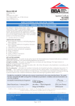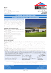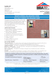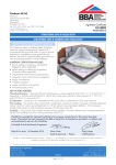
1
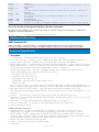
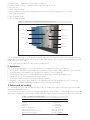
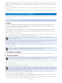
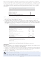
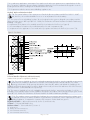
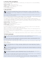
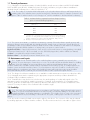
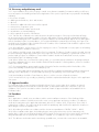
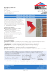
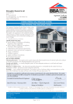
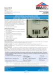
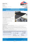
Alumasc Exterior Building Products Ltd APPROVAL INSPECTION TESTING CERTIFICATION White House Works Bold Road Sutton St Helens Merseyside WA9 4JG Tel: 01744 648400 Fax: 01744 648401 TECHNICAL APPROVALS FOR CONSTRUCTION Agrément Certificate 00/3766 e-mail: [email protected] website: www.alumascfacades.co.uk Product Sheet 1 SWISTHERM EXTERNAL WALL INSULATION SYSTEMS SWISTHERM — EPS EXTERNAL WALL INSULATION SYSTEM PRODUCT SCOPE AND SUMMARY OF CERTIFICATE This Certificate relates to the Swistherm — EPS External Wall Insulation (EWI) System, comprising mechanically fixed expanded polystyrene (EPS) insulation boards with a glassfibre reinforcing mesh and render finishes, and suitable for use on new or existing buildings. AGRÉMENT CERTIFICATION INCLUDES: • factors relating to compliance with Building Regulations where applicable • factors relating to additional non-regulatory information where applicable • independently verified technical specification • assessment criteria and technical investigations • design considerations • installation guidance • regular surveillance of production • formal three-yearly review. KEY FACTORS ASSESSED Strength and stability — the system can adequately resist wind loads and, in certain applications, impact damage (see section 6). Behaviour in relation to fire — the system has a Class 0 surface spread of flame classification (see section 7). Risk of condensation — the system can contribute to limiting the risk of interstitial and surface condensation (see section 10). Thermal performance — the system can be used to improve the thermal performance of external walls or contribute to meet the building regulations (see section 11). Durability — with appropriate care, the system should remain effective for at least 30 years (see section 13). The BBA has awarded this Agrément Certificate to the company named above for the system described herein. This system has been assessed by the BBA as being fit for its intended use provided it is installed, used and maintained as set out in this Certificate. On behalf of the British Board of Agrément Date of First issue: 2 February 2012 Brian Chamberlain Greg Cooper Originally certificated on 5 March 2001 Head of Approvals — Engineering Chief Executive The BBA is a UKAS accredited certification body — Number 113. The schedule of the current scope of accreditation for product certification is available in pdf format via the UKAS link on the BBA website at www.bbacerts.co.uk Readers are advised to check the validity and latest issue number of this Agrément Certificate by either referring to the BBA website or contacting the BBA direct. British Board of Agrément Bucknalls Lane Garston, Watford Herts WD25 9BA ©2012 Page 1 of 18 tel: 01923 665300 fax: 01923 665301 e-mail: [email protected] website: www.bbacerts.co.uk Regulations In the opinion of the BBA, Swistherm — EPS External Wall Insulation System, if used in accordance with the provisions of this Certificate, will meet or contribute to meeting the relevant requirements of the following Building Regulations (the presence of a UK map indicates that the subject is related to the Building Regulations in the region or regions of the UK depicted): The Building Regulations 2010 (England and Wales) Requirement: A1 Loading Comment: Requirement: B4(1) External fire spread The system can sustain and transmit wind loads to substrate wall. See sections 6.1 and 6.4 of this Certificate. Comment: The system is classified Class 0 and, therefore, can meet this Requirement. See sections 7.1 to 7.7 and 7.10 of this Certificate. Requirement: C2(b) Resistance to moisture Comment: The system provides a degree of protection against rain ingress. See sections 4.4, 9.1 and 9.2 of this Certificate. Requirement: C2(c) Resistance to moisture Comment: The system contributes to minimising the risk of interstitial and surface condensation. See sections 4.6 and 10.2 to 10.6 of this Certificate. Requirement: L1(a)(i) Conservation of fuel and power Comment: Requirement: Regulation 7 Materials and workmanship Comment: The system is acceptable. See section 13.1 and the Installation part of this Certificate. The system can contribute to meeting this requirement. See sections 11.2 and 11.3 of this Certificate. The Building (Scotland) Regulations 2004 (as amended) Regulation 8(1)(2) Regulation: Standard: 9 1.1 2.6 2.7 3.10 3.15 6.1(b) 6.2 Carbon dioxide emissions Buildings insulation envelope The system can contribute to satisfying these Standards, with reference to clauses (or parts of) 6.1.1(1), 6.1.2(1)(2), 6.1.3(1)(2), 6.1.4(2), 6.1.6(1), 6.1.8(2) 6.1.10(2), 6.2.1(1)(2), 6.2.3(1), 6.2.4(1), 6.2.5(1)(2), 6.2.6(2), 6.2.7(2), 6.2.11(1) and 6.2.13(2). See sections 11.2 and 11.3 of this Certificate. Comment: Standard: Condensation Walls insulated with the system can satisfy this Standard, with reference to clauses 3.15.1(1)(2), 3.15.4(1)(2) and 3.15.5(1)(2). See sections 4.6 and 10.5 to 10.8 of this Certificate. Comment: Standard: Standard: Precipitation Walls insulated with the system will contribute to a construction satisfying this Standard, with reference to clause 3.10.1(1)(2) and 3.10.2(1)(2). See sections 4.4, 9.1 and 9.2 of this Certificate. Comment: Standard: Spread on external walls The system incorporates materials which would not be classed as ‘non-combustible’ as defined in this Standard, with reference to clauses 2.7.1(1)(2), 2.7.2(2) and Annex 2A(1). See sections 7.1 to 7.5 and 7.8 to 7.10 of this Certificate. Comment: Standard: Spread to neighbouring buildings The external surface of the system has a ‘low risk’ surface spread of flame classification, with reference to clauses 2.6.1(1)(2), 2.6.2(1)(2), 2.6.4(1)(2), 2.6.5(1) and 2.6.6(2). See sections 7.1 to 7.5 and 7.8 to 7.10 of this Certificate. Comment: Standard: Building standards — construction Structure The system can sustain and transmit wind loads to the substrate wall. See sections 6.1 and 6.4 of this Certificate. Comment: Standard: Fitness and durability of materials and workmanship The system can contribute to a construction meeting this Regulation. See sections 12.1 and 13.1 and the Installation part of this Certificate. Comment: 7.1(a)(b) Statement of sustainability The system can contribute to meeting the relevant Requirements of Regulation 9, Standards 1 to 6, and, therefore, will contribute to a construction meeting a bronze level of sustainability as defined in this Standard. Comment: (1) Technical Handbook (Domestic). (2) Technical Handbook (Non-Domestic). The Building Regulations (Northern Ireland) 2000 (as amended) Regulation: B2 Fitness of materials and workmanship Comment: Regulation: B3(2) Suitability of certain materials Comment: Regulation: C4(b) Resistance to ground moisture and weather Comment: The system is acceptable. See section 13.1 and the Installation part of this Certificate. The system is acceptable. See section 12.1 of this Certificate. Walls insulated with the system will satisfy this Regulation. See sections 4.4, 9.1 and 9.2 of this Certificate. Page 2 of 18 Regulation: C5 Regulation: D1 E5(a) External fire spread The system has a Class 0 surface and can satisfy this Regulation. See sections 7.1 to 7.7 and 7.10 of this Certificate. Comment: Regulation: Regulation: Stability The system can sustain and transmit wind loads to the substrate wall. See sections 6.1 and 6.4 of this Certificate. Comment: Regulation: Condensation Walls insulated with the system can satisfy this Regulation. See sections 4.6, 10.4 and 10.6 to 10.8 of this Certificate. Comment: F2(a)(i) F3(2) Comment: Conservation measures Target carbon dioxide Emissions Rate The system can contribute to satisfying these Regulations. See sections 11.2 and 11.3 of this Certificate. Construction (Design and Management) Regulations 2007 Construction (Design and Management) Regulations (Northern Ireland) 2007 Information in this Certificate may assist the client, CDM co-ordinator, designer and contractors to address their obligations under these Regulations. See section: 3 Delivery and site handling (3.2) of this Certificate. Additional Information NHBC Standards 2011 NHBC accepts the use of the Swistherm — EPS External Wall Insulation System, when installed and used in accordance with this Certificate, in relation to NHBC Standards, Chapter 6.9 Curtain walling and cladding. Technical Specification 1 Description 1.1 The Swistherm — EPS External Wall Insulation System (see Figure 1) comprises: • ST 1 Composite mortar — a mixture of white Portland cement, quartz sand and other additives supplied as a powder to which clean water is added and can be used as both the base render and adhesive • Swistherm EPS insulation — expanded polystyrene board 1200 mm by 600 mm in a range of thicknesses between 60 mm and 400 mm in increments of 10 mm, with a nominal density of 20 kg·m–3, minimum compressive strength of 70 kN·m–2 and minimum tensile strength perpendicular to the faces of 100 kN·m–2 • Swistherm Mechanical fixings — an anchor of adequate length to suit the substrate and insulation thickness, approved and supplied by the Certificate holder, and selected from: — polyethylene with metal centre pin — polyethylene with metal centre screw — polypropylene with metal centre pin — polypropylene with glass reinforced plastic (GRP) centre pin — stainless steel tube • M.R. Scrim Reinforcement — a one metre wide mesh of multi-stranded, alkali- and slide-resistant glassfibres with a polymer coating, weighing approximately 150 g·m–2, mesh size of about 6.0 mm x 6.0 mm and supplied in 50 m rolls • M.R. High Density Scrim Reinforcement — used with and having the same specification as M.R. Scrim Reinforcement but weighing approximately 500 g·m–2, mesh size about 7.5 mm x 7.5 mm and supplied in 1 m by 23 m rolls • ST Primer — a silicone primer containing fine quartz grains used as a bonding aid and pre-coat • ST Silkolitt — a silicone bonded textured plaster supplied as paste, available in three grades: coarse 1.5 mm, 2.5 mm and 3.0 mm grain size • ST Mineral K — a cementitious textured plaster supplied as powder in 3 mm grain size • ST Silicone Façade Paint — a micro-porous silicone-based paint used as a decorative finish • Swistherm Mineral Fire Breaks. Ancillary materials/components: • Swistherm profiles — a range of standard profiles for such details as wall base, end stop, corner mesh and expansion joint, produced in two main material specifications, either stainless steel number 1.4301 to BS EN 10088-1 : 2005, or galvanized steel strip DX51D + Z275 N-A-U to BS EN 10327 : 2004, with a polyester powder paint finish to BS EN 13438 : 2005. Aluminium or rigid PVC profiles are also available. Profiles are provided to the specifier’s requirements and approved by the Certificate holder • Swistherm Expansion Profile (horizontal and vertical) • sealant — silicone as approved by the Certificate holder • sealing tape Page 3 of 18 • • • • Swistherm Sills — aluminium polyester powder coated sills Swistherm Wall Copings — aluminium polyester powder coated copings PU Foam Filler stainless steel fire fixings. 1.2 Items outside the scope of this Certificate but which may be required for preparatory works include: • M.R. Stabilising Solution • M.R. Fungicidal Wash • M.R. S3 Dubbing Render. Figure 1 Swistherm — EPS External Wall Insulation System adhesive mortar render finish composite mortar mechanical fixing glassfibre mesh insulation board primer substrate base profile 1.3 The insulation boards are mechanically fixed to the substrate. The composite mortar is then trowel-applied to the external face of the board and the reinforcing mesh embedded and left to dry. The primer is applied and finished with façade paint (see section 16). 1.4 All components are subject to routine in-factory quality control. 2 Manufacture 2.1 To ensure product quality is consistently maintained to the required specification, the BBA has: • • • • • • agreed with the Certificate holder/manufacturer the quality control procedures and product testing to be undertaken assessed and agreed the quality control operated over batches of incoming materials monitored the production process and verified that it is in accordance with the documented process evaluated the process for management of non-conformities checked that equipment has been properly tested and calibrated undertaken to carry out the above measures on a regular basis as part of a surveillance process to ensure that standards are maintained and that the product or system remains as Certificated. 3 Delivery and site handling 3.1 The Swistherm EPS insulation boards are delivered to site wrapped in polythene. Each pack carries the product identification and batch numbers. 3.2 Components are delivered to site in packaging and quantities listed in Table 1. Each package carries the product identification, manufacturer’s batch number and the BBA identification mark incorporating the number of this Certificate. Table 1 Component supply details Component Quantity and package ST 1 Composite mortar ST Silkolitt ST Mineral K ST Primer ST Silicone façade paint MR Scrim Reinforcement MR High Density Scrim Reinforcement Swistherm Mechanical fixings 25 kg bag 25 kg plastic tub 25 kg bag 23 kg plastic tub 15 l tub 1.0 m wide, 50 m rolls 1.0 m wide, 23 m rolls boxed by manufacturer Page 4 of 18 3.3 The insulation must be protected from prolonged exposure to sunlight and contact with solvents and bitumen. In addition, the insulation must be stored on a firm, clean, level base, off the ground and under cover until required. Care must be taken when handling the insulation to avoid damage. The boards must not be exposed to open flame or other ignition sources. 3.4 The renders must be stored in dry conditions, off the ground, and protected from excessive heat, moisture and frost at all times. 3.5 The façade paint should be stored in a safe area, under cover, and protected from excessive heat and frost at all times. Assessment and Technical Investigations The following is a summary of the asssesssment and technical investigations carried out on Swistherm — EPS External Wall Insulation System. Design Considerations 4 General 4.1 When installed in accordance with this Certificate, the system is effective in reducing the thermal transmittance (U value) of the walls of new and existing buildings. It is essential that the detailing techniques specified in this Certificate are carried out to a high standard if the ingress of water into the insulation is to be avoided and the full thermal benefit obtained from treatment with the system. 4.2 The system will improve the weather resistance of a wall and provides a decorative finish. However, it may be installed only where other potential sources of moisture penetration have been dealt with separately and there are no signs of dampness on the inner surface of the wall other than those caused solely by condensation. The system can be used to overcome internal condensation. 4.3 Existing buildings subject to national Building Regulations should have wall surfaces in accordance with section 14 Site survey and preliminary work in the Installation part of this Certificate. 4.4 New buildings subject to national Building Regulations should be constructed in accordance with the relevant recommendations of: • BS EN 1996-2 : 2006 — the designer should select a construction appropriate to the local wind-driven rain index, paying due regard to the design detailing, workmanship and materials to be used • BS 8000-3 : 2001. 4.5 Other new buildings, not subject to any of the previous requirements, should also be built in accordance with BS EN 1996-2 : 2006. 4.6 When using the system, consideration must be given to the overall design to minimise the risk of condensation, and the recommendations of BS 5250 : 2002 should be followed. 5 Practicability of installation The system should only be installed by installers who have been trained and approved by the Certificate holder. 6 Strength and stability 6.1 When installed on suitable walls, the system can adequately transfer self-weight and negative and positive (suction and pressure) wind loads normally experienced in the United Kingdom, to the wall. 6.2 Positive wind load (pressure) is transferred to the substrate wall directly via bearing and compression of the render, adhesive and insulation. 6.3 Negative wind pressure (suction) is resisted by the bond between each component. The insulation boards are retained by the external wall insulation system anchors. 6.4 The wind loads on the wall should be calculated in accordance with BS EN 1991-1-4 : 2005. Special consideration should be given to locations with high wind-load pressure coefficients as additional fixings may be necessary. In accordance with BS EN 1990 : 2002, it is recommended that a load factor of 1.5 is used to determine the ultimate wind load to be resisted by the system. 6.5 Assessment of structural performance for individual installations should be carried out by a suitably qualified engineer or other appropriately qualified person to confirm that: • the substrate wall has adequate strength to resist the additional loads that may be applied as a result of installing the system, ignoring any positive contribution that may occur from the insulation system • the proposed system and associated fixing layout provides adequate resistance to negative wind loads (based on the results of site investigation and test results given in Table 3, see section 6.7). Page 5 of 18 6.6 Provided the substrate wall is suitable and an appropriate fixing is used, the mechanical fixings will transfer the weight of the render insulation system to the substrate wall. The number of fixings and the span between fixings should be determined by the system designer. The fixing must be selected to give adequate support to the weight of the system at the minimum spacing given in this Certificate. As a guide, typical characteristic pull-out strengths for the fixings are given in Table 2, however, these values are dependent on the substrate and the fixing must be selected to suit the loads and substrate concerned. A minimum of one metal fixing per square metre is required to satisfy fire regulations (see section 7). Table 2 Fixings — typical characteristic pull-out strengths Fixing type Typical pull-out strength (N)(1) Polypropylene with metal centre screw Polypropylene with metal centre pin Polyethylene with metal centre screw Polyamide with metal centre screw Polyamide with metal centre pin Polypropylene with glass reinforced plastic (GRP) centre pin 1500 1200 1200 900 500 750 (1) Values are determined in accordance with ETAG 014 : 2000 and are dependent on the substrate. 6.7 The resistance forces data given in Table 3 are the results of calculations based upon: • fixings arranged in the pattern described and shown in section 16.10 and Figure 3 • pull-over resistances determined by the BBA from tests on anchors with 60 mm and 90 mm diameter plates (mean value of five tests with a factor of safety of 2.5 applied) • an appropriate number of site-specific pull-out tests conducted on the substrate of the building to determine the minimum resistance to failure of the fixings. The characteristic pull-out resistance should be determined in accordance with the guidance given in ETAG 014 : 2002, Annex D (ie by calculating the mean of the lowest five values and multiplying by 0.6). In accordance with this guideline, a safety factor of two is applied to this figure to establish the design value to resist ultimate loads. Table 3 Example calculation sheet to establish ultimate wind load capacity Factor EPS insulation(1) 60 Thickness (mm) Plate diameter of anchor (mm) Characteristic pull-over resistance(2) (per anchor) (N) Factor of safety Design pull-over resistance(3) (N) Characteristic anchor pull-out resistance(4) (per anchor) (N) Factor of safety(5) Design pull-out resistance(6) (per anchor) (N) Limiting design value(7) (per fixing) (N) Limiting design value per board(8) (with five fixings) (N) Area of board (m2) Limiting pressure (kN·m–2) 60 258 90 282 2.5 103.2 1200 112.8 1200 2 600 103.2 516 600 112.8 564 0.72 0.717 0.783 (1) Calculation based on insulation board 1200 mm by 600 m (total area 0.72 m2) attached by six fixings. (2) Pull-over resistance of insulation over the head of the fixing. (3) The safety factor of 2.5 is based on the assumption that all insulation boards are quality control tested to establish tensile strength perpendicular to the face of the board. (4) See section 6.6. (5) See section 6.7, third bullet point. (6) The pull-out value will be limiting factor on systems fixed through the mesh. (7) The lesser of the board design pull-over resistance and the anchor design pull-out resistance. (8) Board design pull-over resistance multiplied by the number of fixings, based upon the limiting resistance. Impact resistance 6.8 Hard body impact tests were carried out in accordance with ETAG 004: 2000. The system is suitable for use in category I(1) with high density mesh and category II(2) with standard mesh. (1) Use category I — a zone readily accessible at ground level to the public and vulnerable to hard body impacts but not subjected to abnormally rough use. (2) Use category II — a zone liable to impacts from thrown or picked objects, but in public location where the height of the system will limit the size of the impact; or at lowers levels where access to public is primarily to those with some incentive to exercise care. 7 Behaviour in relation to fire 7.1 The surface spread of flame classification for the render in accordance with BS EN 13501-1 : 2007 for the expanded polystyrene system is B-s2,d0. 7.2 This rating applies to the light range of colours covered by this Certificate. 7.3 The insulation material in isolation is combustible and classified as Class E in accordance with BS EN 13501-1 : 2007. Page 6 of 18 7.4 In multi-storey applications, a minimum of one stainless steel anchor per square metre is required above the first floor. The anchor is applied to prevent collapse should the insulation be lost to fire and must be designed to resist the bending and shear stresses resulting from the dead load from the render. 7.5 Requirements under the various national Building regulations are: England, Wales and Northern Ireland 7.6 The external surfaces of the systems are to Class B-s2,d0 in accordance with BS EN 13501-1 : 2007 and, therefore, are considered suitable for use on or at any distance from the boundary. 7.7 The system is for use in buildings less than 18 m in height unless the system is designed in accordance with the design principles given in BRE report (BR 135 : 2003) Fire Performance of External Insulation for Walls of Multi-storey buildings — this gives: • requirements for fire barriers to be installed at each floor level above the first floor (see Figure 2) • a recommendation for barriers to be installed vertically in line with compartment walls • a requirement for the application of one metal anchor per square metre above the first floor (see section 7.4). Figure 2 Fire barrier Scotland Technical Handbook (Domestic and Non-Domestic) Standard 2.6 Spread to neighbouring buildings 7.8 The system is classified as ‘low risk’ combustible materials and, therefore, must be regarded as unprotected areas unless the cladding is attached to the structure of the building and the external wall does not contain openings other than the small openings described in clause 2.6.2b; and the wall behind the cladding (or the cladding itself) has the appropriate fire resistance duration from inside (see Annex 2.A and Annex 2.D of the Domestic and Non-Domestic Technical Handbooks respectively). 7.9 The system is classified as ‘low risk’ combustible materials and, therefore, must not be used within 1 m of the boundary. These materials may be used in installations designed in accordance with the design principles given in BRE report (BR 135 : 2003) Fire Performance of External Insulation for Walls of Multi-storey buildings. 7.10 The insulation systems covered by this Certificate do not incorporate cavities between the insulation and the substrate, however, fire barriers should be incorporated into a construction, where required by the relevant Building Regulations, to maintain the continuity of fire resistance. Further details are given in: England and Wales — Approved Document B, Section 5(1) and Section 8(2) Scotland — Technical Standards 2.2(3)(4) Northern Ireland — Technical Booklet F, Section 3. (1) (2) (3) (4) Dwellinghouses. Buildings other than dwellinghouses. Technical Handbook (Domestic). Technical Handbook (Non-Domestic). Page 7 of 18 8 Proximity of flues and appliances When the system is installed in close proximity to certain flue pipes, the relevant provisions of the national Building Regulations should be met: England and Wales — Approved Document J Scotland — Mandatory Standard 3.19, clause 3.19.4(1)(2) Northern Ireland — Technical Booklet L. (1) Technical Handbook (Domestic). (2) Technical Handbook (Non-Domestic). 9 Rain penetration 9.1 The system will provide a degree of protection against rain ingress. However, care should be taken to ensure that walls are adequately weather tight prior to its application. The insulation systems must only be installed where there are no signs of dampness on the inner surface of the substrate other than those caused solely by condensation. 9.2 Designers and installers should take particular care in detailing around openings, penetrations and movement joints to minimise the risk of rain ingress. 9.3 For externally insulated single-leaf masonry walls, guidance is given in BS EN 1996-1-1 : 2005 and BS EN 998-2 : 2010 on the minimum thickness of render required for the different exposure categories. 9.4 Guidance given in BRE report (BR 262 : 2002) Thermal insulation: avoiding risks should be followed in connection with the weathertightness of solid wall constructions. The designer should select a construction appropriate to the local wind-driven rain index, paying due regard to the design detailing, workmanship and materials to be used. Additional guidance can be found in: England and Wales — Approved Document C, Section 5 Scotland — Mandatory Standard 3.10(1)(2) Northern Ireland — Technical Booklet C, Section 2. (1) Technical Handbook (Domestic). (2) Technical Handbook (Non-Domestic). 9.5 When using the system, consideration must be given to the overall design to minimise the risk of condensation, and the recommendations of BS 5250 : 2002 should be followed. 9.6 At the tops of walls, the systems should be protected by an adequate overhang or other detail designed for use with this type of system (see sections 16.23 and 16.24). 9.7 The fixing of rainwater goods, satellite dishes, clothes lines, hanging baskets and similar items is outside the scope of this Certificate. 9.8 It is essential that the system is installed and maintained in accordance with the conditions set out in this Certificate 10 Risk of condensation 10.1 When using the system, consideration must be given to the overall design to minimise the risk of condensation, and the recommendations of the BS 5250 : 2002 should be followed. 10.2 Designers must ensure that an appropriate condensation risk analysis has been carried out for all parts of the construction, including openings and penetrations at junctions between the insulation system and windows to ensure that condensation does not occur at the surface or within. 10.3 The water vapour resistance factor (µ) for the EPS insulation boards, as taken from BS EN ISO 10456 : 2007, Table 4, is 60. Surface condensation 10.4 Walls will limit the risk of surface condensation adequately when the thermal transmittance (U value) does not exceed 0.7 W·m–2·K–1 at any point and the junctions with other elements and openings comply with section 11.3. 10.5 Walls will adequately limit the risk of surface condensation when the thermal transmittance (U value) does not exceed 1.2 W·m–2·K–1 at any point. Guidance may be obtained from BS 5250 : 2002 (Section 8, Annex D) and BRE report (BR 262 : 2002). Interstitial condensation 10.6 Walls incorporating the system will adequately limit the risk of interstitial condensation when they are designed and constructed in accordance with BS 5250 : 2002, Section 8 and Annex D. 10.7 The system has a water vapour resistance such that, under the types of conditions likely to occur in a dwelling in the United Kingdom, interstitial condensation should not occur in the insulation. 10.8 If the system is to be used on the external walls of rooms expected to have continuous high humidities, care must be taken in the design of the rooms to avoid possible problems from the formation of interstitial condensation. Page 8 of 18 11 Thermal performance 11.1 Calculations of thermal transmittance (U value) should be carried out in accordance with BS EN ISO 6946 : 2007 and BRE report (BR 443 : 2006) Conventions for U-value calculations, using the insulation manufacturer’s declared thermal conductivity (λ90/90 value) of 0.038 W·m–1·K–1. 11.2 The U value of a completed wall will depend on the selected insulation thickness and fixing method, the insulating value of the substrate masonry and its internal finish. Calculated U values for example constructions are given in Table 3 and are based on seven fixings per m2 with the manufacturer’s declared thermal conductivity. Table 3 Insulation thickness required to achieve design U values given in national Building Regulations U value(1) (W·m–2·K–1) EPS Insulation thickness(2) (mm) 0.19 210 0.26 150 0.28 140 0.30 130 (1) Values derived using 200 mm thick dense concrete block with thermal conductivity of 1.75 W·m–1·K–1, 13 mm thick layer of dense plaster with a thermal conductivity of 0.57 W·m–1·K–1 and glassfibre-reinforced plastic nails. Use of other types of fixings should be calculated in accordance with BS EN ISO 6946 : 2007, Annex D. (2) Based upon incremental insulation thickness of 10 mm. 11.3 The systems can maintain, or contribute to maintaining, continuity of thermal insulation around openings and at junctions between external walls and other building elements. Details shown in Figures 8 to 10 will allow use of the default psi values for Accredited Construction details in Emission Rate calculations to SAP 2009 or the Simplified Building Energy Model (SBEM). Guidance on limiting heat loss at junctions can be found in: England and Wales — Approved Documents to Part L and, for new thermal elements to existing buildings, Accredited Construction Details (version 1.0) (for new-build, see also SAP 2009, Appendix K, and the iSBEM User Manual) Scotland — Accredited Construction Details (Scotland) Northern Ireland — Accredited Construction Details (version 1.0). 12 Maintenance and repair 12.1 Regular checks should be made on the installed insulation systems, particularly at joints with other elements, to ensure that ingress of water does not occur. This should verify that architectural details for shedding water clear of the building are present and functioning, and that external plumbing fitments are in good condition. Maintenance schedules should include the replacement and resealing of joints, for example between the insulation systems and window and door frames. The interval between inspections should be considered for each building taking into consideration such factors as the building location and height. Necessary repairs should be effected immediately and the sealant at joints at window and door frames replaced at regular intervals. 12.2 The designer should ensure suitable access is available to enable maintenance inspections to take place safely. 12.3 Damaged areas must be repaired using the appropriate components and the procedures detailed in the Certificate holder’s installation instructions. 12.4 Textured finishes may also become soiled in time, the rate depending on locality and original colour. The appearance may be restored by a suitable powerwash or, if required, by the application of a compatible paint; however, great care should be taken not to adversely affect the water vapour or fire resistance characteristics of the system. If necessary, the advice of the Certificate holder should be sought. 13 Durability 13.1 The results of accelerated ageing tests in accordance with ETAG 004 : 2000 indicate that the system is durable. The system should remain effective for at least 30 years, provided any damage to the surface finish is repaired immediately, and regular maintenance is undertaken. This includes checks on joints in the system and external plumbing fitments to prevent leakage of rainwater into the system, enabling steps to be taken to correct the defects. 13.2 Any render containing Portland cement may be subject to lime bloom. The occurrence of this may be reduced by avoiding application in adverse weather conditions. The effect is transient and is less noticeable on lighter colours. Page 9 of 18 Installation 14 Site survey and preliminary work 14.1 A pre-installation survey of the property is carried out to determine suitability for treatment and the need for any necessary repairs to the building structure before application of the system. A specification is prepared for the building indicating: • the position of beads • detailing around windows, doors and at eaves • dpc level • areas where additional reinforcement will be required • exact position of expansion joints • areas where flexible sealants must be used • any alterations to external plumbing • where required, the position of fire barriers. 14.3 Trial tests are conducted on the wall to determine the pull-out resistance of the proposed mechanical fixings. An assessment and recommendation is made on the type and number of fixings required to withstand the building’s expected wind loading based on calculations using the test data, the relevant wind speed data for the site and together with the Certificate holder’s recommendations. It is recommended that the minimum layout of fixings (see Figure 3) as specified by the Certificate holder, should be followed. The advice of the Certificate holder should be sought to ensure the proposed fixing pattern is sufficient. 14.4 All modifications, such as provision for fire stopping (see sections 7 and 8) and necessary repairs to the building are completed before installation commences. 14.5 Surfaces should be sound, clean and free from loose material. The flatness of surfaces must be checked; this may be achieved using a straight edge spanning the storey height. Any excessive irregularities, ie greater than 10 mm in 1 m, must be made good prior to installation to ensure that the insulation boards are installed with a smooth, in-plane finished surface (M.R. S3 Dubbing Render). 14.6 Where surfaces are covered with an existing render, it is essential that the bond between the background and the render is adequate. All loose areas should be hacked off and reinstated. For further guidance, reference should be made to BS 13914 : 2005. 14.7 On existing buildings, purpose-made window sills must be fitted to extend beyond the finished face of the system. New buildings should incorporate suitably deep sills. 14.8 It is recommended that external plumbing be removed before installation and alterations made to underground drainage, where appropriate, to accommodate repositioning of the plumbing on the finished face of the system. 14.9 New buildings should be of sound masonry, dense or no-fines concrete or framed construction. 14.10 Internal wet work, eg screeding or plastering, should be completed and allowed to dry prior to the application of a system. 15 Approved installers The Certificate holder operates an Approved Installer Scheme for the system, under which installers are trained, approved and regularly reviewed by the Certificate holder, to demonstrate that they are competent to carry out installation of the system in accordance with this Certificate. Details of approved installers are available from the Certificate holder. 16 Procedure General 16.1 Application is carried out in accordance with the current installation instructions of the Certificate holder. 16.2 Weather conditions should be monitored to ensure correct application and curing conditions. The adhesive, render and coating must not be applied at temperatures below 5°C or above 30°C, if exposure to frost is likely or in damp/wet conditions. The render must be protected from rapid drying and should not be applied on elevations in direct sunlight or where the substrate is hot. 16.3 All rendering should be in accordance with the relevant recommendations of BS EN 13914-1 : 2005. 16.4 Before installation takes place, the building designer must confirm where items such as rainwater goods, satellite dishes, clothes lines and hanging baskets will be placed. The fixing points for these items must be specifically designated and built into the system as the insulation is installed. This is outside the scope of this Certificate. 16.5 The adhesives and render must be mixed using a paddle mixer; conventional concrete mixers are unsuitable. Page 10 of 18 Positioning and securing insulation boards 16.6 The Swistherm base profile is secured to the external wall above the damp-proof course using the approved profile fixings at approximately 300 mm centres. Insulation boards are initially fixed to the external surfaces of the walls using adhesive mortar to secure the boards in place. 16.7 The board adhesive is prepared for use by mixing the contents of each 25 kg bag with approximately 5.8 litres of water using an electrically driven paddle mixer. The material is left to stand for approximately five minutes and mixed again with, if required, a small addition of water to give a smooth, workable consistency. Care should be taken not to over-mix. 16.8 The board adhesive is applied to the back of the slabs either by notch trowel to achieve a full bond, or around the whole perimeter of the board and in 6 equal sized dabs distributed over the remaining area of the board for an uneven background. 16.9 The insulation slabs must be pressed firmly to the substrate immediately after application of the board adhesive and butted tightly together with the vertical joints staggered. Any delay may result in a weak bond. Joints in the system larger than 2 mm should be filled with slithers of EPS board or PU Foam and any high spots or irregularities removed with a rasp over the whole surface. 16.10 The first run of insulation is positioned on the base profile. Holes are drilled into the substrate to the required depth through the insulation at the corners of each slab and at positions which will allow a minimum of eight fixings per square metre at edge zones and four fixings per square metre in the main area of the wall (see Figure 3). Around openings, additional fixings should be used at 300 mm centres. The mechanical fixings are inserted and tapped or screwed firmly into place, securing the insulation to the substrate. Subsequent rows of slabs are positioned so that the vertical board joints are staggered and overlapped at the building corners and so that the board joints do not occur within 200 mm of the corners of openings. Figure 3 Insulation board fixing pattern 16.11 Care must be taken to ensure that all slab edges are butted tightly together, and alignment should be checked as work proceeds. 16.12 To fit around details such as doors and windows, insulation slabs may be cut with a sharp knife, fine-tooth saw or hot wire. If required, purpose-made Swistherm sills are fitted. They are designed to prevent water ingress and incorporate drips to shed water clear of the system. 16.13 Installation continues until the whole wall is completely covered including, where appropriate, the building soffits and eaves (see Figure 4). Page 11 of 18 Figure 4 Roof eaves detail insulation within eaves joined to Swistherm EPS Swistherm EPS Movement joints 16.14 Generally movement joints are not required in the system. If an expansion joint is incorporated in the substrate it must be replicated through the Swistherm system (see Figure 5). Figure 5 Movement joint movement profile movement profile Reinforcing 16.15 The ST1 Composite Mortar is prepared by mixing the contents of each 25 kg bag with 5.8 litres of clean water using the same method as for the adhesive (see section 16.7). 16.16 Prior to the render coat, a bead of Swistherm Low Modulus Silicone Mastic with Swistherm Sealing Tape or a Swistherm APU Profile, is installed at window and door frames, overhanging eaves, gas and electric meter boxes, wall vents or where the render abuts any other building material or surface. For non-insulated reveals just a bead of Swistherm Low Modulus Silicone Mastic is required (see Figure 6). Page 12 of 18 Figure 6 Detail around window and door frames silicone sealant corner bead sealing tape and silicone sealant corner bead 16.17 The basecoat render is applied either by spray equipment or stainless steel trowel to the surface of the dry insulation to a minimum thickness of 5 mm. The mesh is bedded immediately into the basecoat with 75 mm minimum overlap at joints and must be in the upper third of the basecoat render. Additional pieces of reinforcing mesh (250 mm x 500mm) are used diagonally at the corners of openings, as shown in Figure 7. Corner details are reinforced using the Swistherm Corner Bead. Figure 7 Additional reinforcement at openings 50 0 25 0 45 ° glassfibre mesh 16.18 Stop beads are positioned vertically, eg at party wall positions where the adjoining house does not require treatment. Rendering and finishing 16.19 The drying period of any render will depend on the applied thickness and weather conditions; however, the basecoat must be left to harden for 3 to 5 days and any contaminants such as grease and chalking removed before the ST Primer is applied by roller or brush. The ST Primer is allowed to dry before application of the ST Silkolitt or ST Mineral K renders. Page 13 of 18 16.20 The ST Mineral K is prepared by mixing the contents of each 25 kg bag with approximately 5.5 litres of cold, clean water, using the same method as for the ST1 Composite Mortar and adhesive. The ST Mineral K is applied by stainless steel trowel to the grain size; 3 mm. The ST Silkolitt is supplied ready to use although a maximum of 2% clean water can be mixed into the 25 kg tub prior to application. The ST Silkolitt is applied by stainless steel trowel to the grain size; 1.5 mm, 2.5 mm or 3.5 mm. Both the ST Mineral K and ST Silkolitt are textured in a circular motion with a plastic trowel until the desired effect is achieved. 16.21 To prevent the render from drying too rapidly, it should not be applied in direct sunlight and continuous surfaces should be completed without a break. 16.22 Depending on weather conditions, the ST Mineral K should be allowed to dry for approximately ten days before application of ST Silicone Façade Paint. ST Silkolitt is a through coloured product that does not require an additional paint coat. 16.23 The decorative finish should not be applied in wet weather, at temperatures below 5°C or when frost is expected. Freshly coated work should be protected from rain. 16.24 At the tops of walls, the system should be protected by an adequate overhang or by an adequately sealed purpose-made flashing (see Figure 8). 16.25 Care should be taken in the detailing of the system around openings and projections to prevent water ingress (see Figures 5, 6 and 7). 16.26 On completion of the installation, external fittings, eg rainwater goods, are re-fixed through the system into the substrate (outside the scope of this Certificate). Figure 8 Detail at tops of walls coping stop bead Page 14 of 18 Figure 9 Window sill detail sealing tape and silicone sealant or APU bead 75 mm Figure 10 Corner detail corner bead Page 15 of 18 Technical Investigations 17 Tests An examination was made of data relating to: • • • • • • • • • • • component characterisation density of insulation slab heat/spray cycling resistance to freeze/thaw impact resistance water absorption of render water vapour permeability. surface spread of flame tests to BS 476-7 : 1987 pull-out strength of fixings durability of finish thermal conductivity. 18 Investigations 18.1 The manufacturing process, the methods adopted for quality control of manufactured and bought-in components, and details of the quality and composition of the materials used, were examined. 18.2 An assessment of the risk of interstitial condensation was undertaken. 18.3 The practicability of installation and the effectiveness of detailing techniques were examined. Page 16 of 18 Bibliography BS 476-6 : 1989 Fire tests on building materials and structures — Method of test for fire propagation for products BS 476-7 : 1997 Fire tests on building materials and structures — Method of test to determine the classification of the surface spread of flame of products BS 5250 : 2002 Code of practice for control of condensation in buildings BS 8000-3 : 2001 Workmanship on building sites — Code of practice for masonry BS 8200 : 1985 Code of practice for design of non-loadbearing external vertical enclosures of buildings BS EN 998-2 : 2010 Specification for mortar for masonry — Masonry mortar BS EN 1990 : 2002 Eurocode — Basis of structural design BS EN 1991-1-4 : 2005 Eurocode 1 : Actions on structures — General actions — Wind actions BS EN 1996-1-1 : 2005 Eurocode 6 : Design of masonry structures — General rules for reinforced and unreinforced masonry structures BS EN 1996-2 : 2006 Eurocode 6 : Design of masonry structures — Design considerations, selection of materials and execution of masonry BS EN 13501-1 : 2007 Fire classification of construction products and building elements — Classification using test data from reaction to fire tests BS EN 13914-1 : 2005 Design, preparation and application of external rendering and internal plastering — External rendering BS EN ISO 6946 : 2007 Building components and building elements — Thermal resistance and thermal transmittance — Calculation method ETAG 004 : 2000 Guideline for European Technical Approval of External Thermal Insulation Composite Systems with Rendering Page 17 of 18 Conditions of Certification 19 Conditions 19.1 This Certificate: • relates only to the product/system that is named and described on the front page • is issued only to the company, firm, organisation or person named on the front page — no other company, firm, organisation or person may hold or claim that this Certificate has been issued to them • is valid only within the UK • has to be read, considered and used as a whole document — it may be misleading and will be incomplete to be selective • is copyright of the BBA • is subject to English Law. 19.2 Publications, documents, specifications, legislation, regulations, standards and the like referenced in this Certificate are those that were current and/or deemed relevant by the BBA at the date of issue or reissue of this Certificate. 19.3 This Certificate will remain valid for an unlimited period provided that the product/system and its manufacture and/or fabrication, including all related and relevant parts and processes thereof: • are maintained at or above the levels which have been assessed and found to be satisfactory by the BBA • continue to be checked as and when deemed appropriate by the BBA under arrangements that it will determine • are reviewed by the BBA as and when it considers appropriate. 19.4 The BBA has used due skill, care and diligence in preparing this Certificate, but no warranty is provided. 19.5 In issuing this Certificate, the BBA is not responsible and is excluded from any liability to any company, firm, organisation or person, for any matters arising directly or indirectly from: • the presence or absence of any patent, intellectual property or similar rights subsisting in the product/system or any other product/system • the right of the Certificate holder to manufacture, supply, install, maintain or market the product/system • individual installations of the product/system, including their nature, design, methods, performance, workmanship and maintenance • any works and constructions in which the product/system is installed, including their nature, design, methods, performance, workmanship and maintenance • any loss or damage, including personal injury, howsoever caused by the product/system, including its manufacture, supply, installation, use, maintenance and removal • any claims by the manufacturer relating to CE marking. 19.6 Any information relating to the manufacture, supply, installation, use, maintenance and removal of this product/ system which is contained or referred to in this Certificate is the minimum required to be met when the product/system is manufactured, supplied, installed, used, maintained and removed. It does not purport in any way to restate the requirements of the Health and Safety at Work etc. Act 1974, or of any other statutory, common law or other duty which may exist at the date of issue or reissue of this Certificate; nor is conformity with such information to be taken as satisfying the requirements of the 1974 Act or of any statutory, common law or other duty of care. British Board of Agrément Bucknalls Lane Garston, Watford Herts WD25 9BA ©2012 Page 18 of 18 tel: 01923 665300 fax: 01923 665301 e-mail: [email protected] website: www.bbacerts.co.uk