1
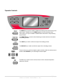
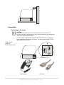
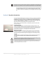
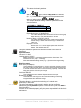
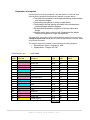
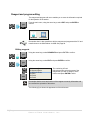
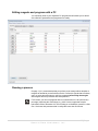
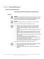
® A Division of General Data Healthcare Histology Innovation for a NEW Generation Pub No.: OM SS2030-1 August, 2014, Version 1.0 SS-2030-120 Operator’s Manual SHURStain™ 2030 Product Name Linear Slide Stainer Here Catalog # SS-2030-120 Copyright© 2009 General Data Company. All rights reserved This document may not be copied in whole or in part or reproduced in any other media without the express written permission of TBS-A Division of General Data Healthcare, or General Data Healthcare. Please note that under copyright law, copying includes translation into another language. General Data Healthcare TBS- A Division of General Data Healthcare Corporate Headquarters 4354 Ferguson Drive Cincinnati, Ohio 45245 Tel. 513-752-7978 Fax.513-965-3636 3014 Croasdaile Road Durham, NC 27705 Tel. 919-384-9393 Fax. 919-384-9595 User Resources and Customer Support Contact your General Data Healthcare representative for customer support. For the latest information on TBS products and services, please visit the TBS website at: www.trianglebiomedical.com. Scope This document contains basic information on the use and operation of the SHURStain™ Linear Slide Stainer SS2030, and assumes you have received basic training on the instrument. Please contact your General Data Healthcare representative for information not provided in this manual. Intended Use Before operating the instrument, please read these instructions carefully to familiarize yourself with its proper operation and functions. The SHURStain™ Linear Slide Stainer SS-2030 is a highly efficient Slide Stainer designed to for the processing and staining of tissue for analysis. Only skilled or specially trained personnel must operate the instrument. The marked safety measures as well as the regulations of your respective lab must strictly be observed. Installation Procedure The SHURStain™ Linear Slide Stainer SS-2030 must be installed, and instrument performance is to be verified, at the customer site by trained General Data Healthcare representatives. Disclaimers This manual is not a substitute for the detailed operator training provided by General Data Healthcare, or for other advanced instruction. A GDHC representative should be contacted immediately for assistance in the event of any instrument malfunction. 3|Page General Data Healthcare, Inc. Instrument Compliance TBS – A Division of General Data Healthcare, Inc. hereby declares the equipment specified conforms to the Classifications(s), Directives(s), and Standard(s) set forth in this document. Certifications: CE, UL/CSA 4|Page General Data Healthcare, Inc. Operator Controls The DRAIN key is used to enable or disable the draining of the racks as they leave each trough. If enabled, the word DRAIN appears on the monitoring screen. This function can only be enabled or disabled when the Stainer is not performing any processes. The FUNCTION key is used to abort all staining processes and return the stainer to its starting position. The LOAD key is used to confirm the steps of the loading process. The UNLOAD key is used to confirm the steps of the unloading process. The arrow keys are used for navigation (option selection) within the various menus and the middle ENTER key for confirming the chosen option. The ESC key is used to exit the various menus in which values and operation options are entered. 5|Page General Data Healthcare, Inc. TableofContents Copyright© 2009 General Data Company. All rights reserved............................................... 3 Instrument Compliance ............................................................................................................ 4 Operator Controls ..................................................................................................................... 5 Section 1 | Safety....................................................................................................................... 7 Safety Precautions .................................................................................................... 7 Hazards ..................................................................................................................... 8 Documentation .......................................................................................................... 9 Conditions for the transportation of the instrument .................................................... 9 Section 2 | Technical Data ...................................................................................................... 10 Section3 | Preparation/Installation ........................................................................................ 11 Connection .............................................................................................................. 12 Connecting to the mains .................................................................................... 12 Water inlet and outlet ......................................................................................... 13 Rinsing trough water connection ....................................................................... 13 Section 4 | Operation .............................................................................................................. 14 Introduction .............................................................................................................. 14 Slide stainer components ........................................................................................ 15 Menus and options .................................................................................................. 16 Main menu ......................................................................................................... 16 Configurations and settings ............................................................................... 17 LANGUAGE ....................................................................................................... 17 CLOCK .............................................................................................................. 18 Advanced configurations ................................................................................... 20 Programming ........................................................................................................... 21 Preparation .............................................................................................................. 21 List of reagents .................................................................................................. 21 Preparation of programs .................................................................................... 22 Reagent layout chart.......................................................................................... 25 Reagent and program editing .................................................................................. 26 Editing reagents ................................................................................................. 26 Entering programs ............................................................................................. 27 Editing reagents and programs with a PC ............................................................... 29 Running a process ................................................................................................... 29 Loading procedure ................................................................................................... 30 Monitoring the process ............................................................................................ 33 Unloading procedure ............................................................................................... 34 Section 5 | Cleaning & Maintenance ...................................................................................... 35 Annual routine maintenance .................................................................................... 35 Cleaning............................................................................................................. 35 Replacing the filter ............................................................................................. 36 Alarm and attention messages ................................................................................ 36 Battery operation ............................................................................................... 37 Disposal of the instrument after final shutdown ....................................................... 37 6|Page General Data Healthcare, Inc. Section 1 | Safety The installation and normal use of the Slide Stainer is simple and safe if you observe the instructions given in this manual. Should the equipment be used for unauthorized purposes or uses not specified by the manufacturer, safety may be impaired. Input and output circuits are isolated from the main power supply. However, those situations which could be constitute a risk for laboratory personnel or equipment, are distinguished in this manual with the following symbols and warning messages: This sign, symbolizing DANGER, means that injury to persons as well as material damage to the unit may occur if these instructions are not observed. For your own safety, observe these instructions carefully. This sign, symbolizing CAUTION, means that damage to the unit may occur if these instructions are not observed. For a long service life of the unit, observe these instructions carefully. This INFORMATION sign draws the user’s attention to important details and additional information about the device, and should therefore especially be taken into account. All persons who are required to operate and program the Slide Stainer should read and fully understand these instructions before using the device. Warning of biological danger. Warning of radioactive danger. Safety Precautions The operator's safety is affected, when the instrument is not operated in accordance with this instruction manual. Apart from the instructions given in this manual, the personnel involved in operating the Slide Stainer should know and observe the general guidelines and rules for safety and hygiene applicable to the workplace where the unit is installed. Please observe the following general precautions during operation of this instrument. Failure to comply with these precautions violates safety standards and the intended use of the instrument. Especialidades Médicas General Data Healthcare is not liable for misuse of the instruments and failure to comply with basic safety requirements. 7|Page General Data Healthcare, Inc. Hazards Instrument grounding The instrument is supplied with a 110/220 V AC mains adapter with a 12 V DC output transformer. The power outlet must be connected to the protective earth and must meet the International Electrotechnical Commission (IEC) regulations. Danger in explosive environment The instrument must not be operated in the presence of flammable gases. Moreover, the instrument must not be exposed to conditions whereby dangerous gas concentrations can occur. Hazard of radio-active radiation When working with radioactive specimens observe all applicable radiation safety procedures. When working with radioactive contaminated material, appropriate safety and disinfecting measures must be carried out. According to the rules and regulations concerning the handling of radioactive contaminated material of the respective laboratory, safety clothing (e.g. particle mask, gloves, protective shoe covers) must be worn. Radioactive contaminated waste must be disposed of according to the respective regulations. Chemical hazard When working with the Slide Stainer, sometimes it is necessary to handle flammable, dangerous fluids. Only trained and qualified laboratory professionals, being aware of the potential dangers and being capable of handling those fluids properly, are allowed to use the instrument. Before handling dangerous liquids, you must make sure to have read and understood the MSDS and specifically understood the safety instructions and the instructions for proper disposal. When the instrument is not in operation, the reagent troughs should be covered with the two stainless steel covers supplied to minimize the evaporation of the solvents. Wastewater treatment According to environmental regulations, the occurring waste water should be drained into a discharge channel with subsequent biological/chemical purification. Hazard of infection Specimens used during the intended operation of the instrument might potentially be infectious. For this reason, it is recommended to observe the general laboratory regulations concerning protection against danger of infection. Information on decontamination media, their use, dilution and effective range of application can be read in the Laboratory Biosafety Manual: 1984 of the World Health Organization. 8|Page General Data Healthcare, Inc. When working with infectious material, appropriate safety and disinfection measures must be carried out. According to the rules and regulations concerning the handling of infectious material of the respective laboratory, safety clothing (e.g. particle mask, gloves, protective shoe covers) must be worn. Infectious waste must be disposed of according to the respective regulations. Hazards associated with faults caused by electromagnetic interference To avoid the hazard of malfunction of an instrument, it must only be operated in a controlled electromagnetic environment. This means that transmitters such as mobile phones must not be operated in their close vicinity. In case of malfunctions and/or service work, please turn off the instrument and contact your local dealer. Hazards associated with the device’s moving parts Due to the potential hazards associated with the operation of devices with moving parts, the Slide Stainer must only be used by professionals or properlytrained personnel. We recommend that the unit should not be handled with the cover open, except during loading and unloading, and in accordance with the safety conditions detailed below. To avoid danger, moving speed has been reduced. Documentation This instruction manual will be supplied together with each instrument. Further copies can be ordered at the Technical Service Address by giving the serial number of the instrument, the version of the instruction manual and the date of issue. This instruction manual is available in English and Spanish Errors and omissions accepted. Subject to amendment and improvement without further notice. Conditions for the transportation of the instrument Repair or maintenance work is normally carried out at the site of installation. If this is not possible for some special reasons, the instrument can be returned to General Data Healthcare. The contact address can be found at the end of this instruction manual. For transportation outside closed buildings use the original packing. If the original packing is no longer available, please contact your local General Data Healthcare representation. 9|Page General Data Healthcare, Inc. Section 2 | Technical Data General information Power Requirements 12V DC - 3A Protection class 1 Classification in accordance with IEC 1010 Pollution degree 2 Overvoltage category II Operating temperature range: 10 - 40°C Relative air humidity: 10 - 80% non-condensing Operating conditions FOR INDOOR USE ONLY Dimensions and weight Dimensions 1200 x 440 x 368 mm (W x D x H) Weight when unloaded and without packaging 55 kg Total weight with packaging 110 kg Operating capacity Processing capacity Up to 5 racks at a time, depending on the programs, load frequency and device configuration. Simultaneous performance of up to 5 different staining protocols Load capacity per rack 30 slides No. of programs in the memory Stores up to 20 programs, each with up to 50 steps No. of reagents in the memory Maximum 52 (32 programed and 20 user-configurable) Immersion time 1 s - 59 m 59 s per step. Number of stations 20 Reagent stations Maximum 18 Reagent tray volume 300 ml Cleaning stations Maximum 3 Loading stations Maximum 2 Unloading stations Maximum 3 Fume extraction Active carbon filter Battery life 2 hours (lithium-ion batteries) 10 | P a g e General Data Healthcare, Inc. Section3 | Preparation/Installation Before removing the Slide Stainer from their shipping package, carefully inspect the wooden case for any damage which may have occurred during transport. Should you detect any sign of damage, do not open the case and immediately report the situation to the transport agency. After removing instrument from its package, inspect it carefully for damage. Should any be noted, immediately notify the distributor from whom the unit was purchased. Remove the protective pieces and elements used for transportation. Please keep the original packaging and protective pieces in case the device needs to be returned. Check that the following items have been supplied: Items included in the box Basic device 20 reagent troughs 3 complete water troughs with fittings. 3 water supply tubes with fittings for water troughs 1 tool to cut the trough water supply tubes 2 reagent trough covers (for 10 trough) 5 racks + supports (30 slides) 1 active carbon filter 1 mains adapter with 12 V DC output transformer 1 "D" power cable 1 "UK" ST-BU F5A power cable 1 "USA-C-J" power cable 1 USB cable for connection to PC 1 water supply hose (1.5 m) complete with ¾” connection fittings 1 corrugated drain hose (3 m) 1 set of clips for drain hose 1 spirit level 1 user manual Remove the protective elements securing the robotic arm. Do not attempt to move it manually. The robotic arm will move to its starting position the first time the instrument is turned on. When choosing where to install the instrument, as well as its dimensions, also take into account its weight. See the dimensions and weight on page 10. Place the instrument on a stable and level surface. Use the spirit level supplied to ensure that the Stainer is completely horizontal. Make sure that there is enough space to fully lift the covers and allow air to circulate. The fume extractor outlet is located at the back of the instrument. For correct ventilation of the instrument a minimum space of 100 mm from wall should be kept free. 11 | P a g e General Data Healthcare, Inc. Connection Connecting to the mains CAUTION Electronics of the Slide Stainer are protected and screened. However, the instrument should not be sited near to heavy electrical machinery generating heat, vibrations or strong electrical noises. The slide stainer is supplied with a power cable and transformer to be plugged into a standard socket with earth connection. The power supply socket is on the right-hand side of the device. 1 Power switch 2 USB port 3 Power supply socket Mains adapter USB cable 12 | P a g e General Data Healthcare, Inc. Water inlet and outlet The water inlet is connected to a standard household appliance hose with a ¾” threaded fitting supplied with the device. The water supply must be equipped with a stopcock (not supplied) to enable it to be turned off. The hose supplied for connection to the water outlet has an inner diameter of 20 mm and must be attached to the outlet nozzle with the hose clip supplied. Be sure that the drain level is always at a lower level than the unit and the hose is always hanging downwards. Rinsing trough water connection One of the main features of the Slide Stainer is its modularity and adaptability to user needs. The Slide Stainer can have up to three rinsing troughs with water in any station between 3 and 17. To determine in which stations the water troughs should be located, consult the person responsible for programming or the pathologist, who will determine the optimum positions for the type of process to be performed. In stations 18, 19 and 20, there are three water outlets with rapid self-locking fittings, which have to be connected, with the flexible hoses supplied (cut to a suitable length), to the troughs in the stations that have been selected as rinsing troughs. The length of the tube (L) will depend on the position of the water intake station and the destination station. Length L in mm is calculated with the formula: (Nt - Nc) * 55 - 16 Nt is the number of the station in which the water inlet is located. Nc is the number of the station containing the trough to be connected. 55 is the distance in mm between the troughs and water inlets. 16 is the measurement in mm taken up by the fittings. It is recommended that you use the outlet of station 18 to feed the station closest to the beginning, station 19 for the middle one and station 20 for the one nearest the end. 13 | P a g e General Data Healthcare, Inc. Remember that the way that the water troughs are arranged will be determined by the processes to be carried out in order to optimize the performance of the Slide Stainer. For the example processes shown here (Hematoxylin/eosin and Papanicolaou), the optimum stations are 6, 8 and 10, which correspond to lengths L of 644 mm, 589 mm and 534 mm respectively. See the reagent layout chart on page 22. Section 4 | Operation Introduction If you are using the Slide Stainer for the first time, before you start any real staining processes, you are strongly advised to familiarize yourself with the handling and programming of the device. To do so, we suggest that you perform some process simulations without samples or reagents. You can allow the water troughs to be filled, which will also verify that they can fill up and drain correctly. Before starting to work with the Stainer, it is advisable to perform a status check. Check the following: Power Requirements Check that the power switch is on and that voltage is reaching the device. The window in the bottom left-hand corner illuminates, except when it is being powered by the backup battery (for more information about autonomous operation with the backup battery, see page 37). The display screen also illuminates. Water inlet and outlet Check that the stopcock for the device’s water supply is turned on and the drain connected. On page 19, you will find the procedure for forcing the entry of water into the previously-connected troughs and verifying that it is functioning correctly. Troughs The Slide Stainer is equipped with 20 stations, which correspond to the location of 20 troughs. The first ones are used for loading racks and the last ones for unloading. Check that the 20 troughs are positioned correctly and not inverted. If they are not positioned correctly, significant mechanical problems can occur. To prevent the reagents from overflowing, the troughs should only be filled up to the level indicated on the inner recess. 14 | P a g e General Data Healthcare, Inc. Note that the reagent that each trough should contain is determined by the previously-established reagent layout chart. See page 22. It is possible to have 1 or 2 loading troughs and 1, 2 or 3 unloading troughs. See Setup > Stations on page 20 The position of the water troughs is defined during installation. See page 13 Robotic arm Check that the robotic arm is located on the left-hand side of device and in a raised position (starting position). If not, turn the unit’s power switch off and then on. Rack collection. To check that the robotic arm is collecting the racks properly, see the MOVEMENT procedure on page 19. Slide stainer components The figure below shows the Slide Stainer’s different components. 1. 2. 3. 4. 5. Loading door Central door Unloading door Robotic arm Slide rack (maximum 5) 6. Troughs (20) 7. Display screen and keypad 15 | P a g e General Data Healthcare, Inc. Menus and options Main menu SS-30 Slide Stainer V 1.6 MAIN MENU STAIN STAIN EDIT SETUP SERVICE EDIT SETUP The main menu shows the four main options. Use the arrow keys to highlight the option you wish and press ENTER. SERVICE This is the normal operation option for performing processes. It enables you to select the program to run and control the loading and unloading of the racks in the troughs. This allows you to enter and edit programs with the keypad. Remember that you can also edit programs with a PC and then transfer them to the Stainer via a USB. This enables you to adjust the stainer settings, such as language, date, speed, agitation, etc. Technical Support Service: This provides access to advanced functions which must only be modified by authorized personnel. 16 | P a g e General Data Healthcare, Inc. Configurations and settings STAIN EDIT Before starting the first staining process, some parameters have to be configured in the EDIT and SETUP menus. Once the settings have been adjusted and the reagents and programs edited, the STAIN process can be started. See the details of how to run a staining process on page 26. REAGENTS This enables you to enter a numbered list with the reagents used. This list is merely informative and is used to facilitate the entering of the names of the reagents during program editing. This enables you to enter the reagents. See an example reagent list on page 21. VIEW/EDIT This enables you to selectively delete reagent positions. DELETE PROGRAMS Before starting a staining process, the Stainer needs to be provided with the sequence of steps that each rack must follow. The Programming Forms must be previously defined. See page 22. This enables you to enter programs. View the editing procedure in detail on page 26. VIEW/EDIT This enables you to selectively delete programs. DELETE SETUP Some of these settings can only be configured during initial device start-up (e.g. language, clock). Others will only require changes if so decided by the pathologist responsible for the procedure (reagents, shake, speed, etc.) Also included here are the parameters that control the fume filter and ventilation. Each option includes a brief summary of its function. Use the arrow keys to select the language and then press ENTER. LANGUAGE SPANISH ENGLISH DEUTCH FRENCH ITALIAN RUSSIAN 17 | P a g e General Data Healthcare, Inc. Use the arrow keys to select each parameter and then press ENTER. Within each option, use the arrow keys to increase or decrease the value and then press ENTER to confirm. CLOCK Clock edit menu Edit date: DD/MM/YY Edit hour: HH:MM:SS Type: 12/24H Dip of the rack within the trough. DIP The amplitude, number of agitations and agitation speed of the rack in the reagent and rinsing troughs can be adjusted. REAGENT This affects the reagent stations. It is possible to define up to 4 dip modes, each with separate parameters. With the arrows, select the Dip mode to be defined (01... 04). Press ENTER to access each of the parameters and select the value using the and arrows. The example shows the editing of Mode 01 parameters for the reagent stations. REAGENT S. - [MODE 01] Dip Amplitude (mm.) Dip number Dip speed 20 4 2 Dip amplitude (mm.) 10-20-30 This value determines the vertical travel of the rack during dip within the trough. The standard value is 20 mm. Number of dips: 1-2-3-4-5-6-7-8-9-10 This value determines the number of times the rack will be moved during dip within the reagent trough. The standard value is 4. Dip speed: 1-2-3-4 Please note: value 1 is the highest speed and value 5 the lowest. The standard value is 2. 18 | P a g e General Data Healthcare, Inc. This affects the cleaning stations. With the arrows, select the Dip mode to be defined (01... 04). Press ENTER to access each of the parameters and select the value using the and arrows. The example shows the editing of Mode 01 parameters for the cleaning stations. CLEANING S. - [MODE 01] Dip Amplitude (mm.) Dip number Dip speed 40 4 2 Dip amplitude (mm.) 20-30-40-50-60 This value determines the vertical travel of the rack during dip within the trough. The standard value is 40 mm. Number of dips: 1-2-3-4-5-6-7-8-9-10 This value determines the number of times the rack will be moved during dip within the reagent trough. The standard value is 4. Dip speed: 1-2-3-4 Please note: value 1 is the highest speed and value 5 the lowest. The standard value is 2. SPEED This option enables the speed of the vertical movement of the rack to be determined. Speed edit menu Lift speed: 1-2-3-4-5 Lowering speed: 1-2-3-4-5 Please note: value 1 is the highest speed and value 5 the lowest. The standard value is 3 (Lift) – 2 (lowering). Note that the slowest lifting speeds (e.g. 4, 5) produce less reagent drag. Water flow menu Water valve (closed/open) WATER This enables you to manually open or close the solenoid valve that controls the entry of water into the Stainer. It is used to check trough filling time and to ensure that water flow does not exceed draining capacity. Check that the filling time is about 10 seconds per trough. Valve time: MM:SS This indicates how much time has elapsed with the valve open. Rinsing time: 30-60-90 This determines how long water will continue circulating in the rinsing troughs after the rack leaves the trough. MOVEMENT This option allows you to check the functioning of the robotic arm. Select Setup > Movement. The device requests you to place a rack in station 1 and to confirm the placement by pressing ENTER to perform a rack collection cycle. Press ESC to cancel the option. If the rack is not collected properly, notify the person responsible for the device’s maintenance. 19 | P a g e General Data Healthcare, Inc. Fan edit menu This option defines filter usage time and useful life, as well as fan usage time. FILTER Programed Time (hr.) 0...250 This time depends on how long the fan has been operating. It determines the operating time in hours (with the fan running). Its value will also depend on the reagents used and the type of filter (see the filter supplier’s instructions). FILTER Remaining Time (hr.) This indicates the time remaining before the stainer emits a “change filter” alarm. Reset This option should only be enabled after a filter change. It resets the filter usage time. Fan On First Time (sg): 0 … 300 FAN This establishes how long the fan should operate each time the device is turned on with the power switch. Once this time has elapsed, the fan switches off and then switches back on and off in accordance with the programed on and off times. Fan Off Time (sg): 0 … 900 Normal value 300 s Fan On Time (sg): 0 … 120 Normal value 60 s PASSWORD This option defines the codes for access to the different levels of changes in the stainer’s parameters for 2 administrators and 4 users. (Grey icon disabled / Green icon enabled) ADMIN1 ADMIN2 ADMINISTRATOR USER1 USER2 USER3 USER4 USER Loading stations: 1-2 STATIONS This defines the number of stations that will be assigned for the loading of racks on the left-hand side of the Stainer. The normal value is 2. Unloading stations: 1-2-3 This defines the number of stations that will be assigned for the unloading of racks on the right-hand side of the Stainer. The normal value is 3. RACK PRIORITY This menu allows you to establish whether the running of staining processes should be prioritized by enter order or optimized time. Use the arrow keys to select the desired option and then press ENTER to confirm. Advanced configurations Technical Support Service This menu’s options are reserved for technical support service. SERVICE 20 | P a g e General Data Healthcare, Inc. Programming The two most outstanding features of the SHURStain™ Linear Slide Stainer SS2030 are: Its ability to operate in multi-load mode. Its great versatility in determining operating parameters: almost all process parameters are freely configurable. This feature enables the Slide Stainer to perform up to 5 processes simultaneously. This means that it is possible to start other staining processes (up to 5) without the need to wait for processes to finish. Multi-load mode This feature greatly improves the performance of the Slide Stainer, enabling it to achieve high levels of productivity. Preparation Before using the Stainer, the following must be prepared in advance: A list of reagents The staining program(s) The reagent layout chart(s) List of reagents To facilitate the entering and documenting of programs in the Slide Stainer, it is recommended that you create a List of Reagents to enter into the Stainer. See page 26. This assignment of reagents is purely for illustrative purposes. No. Reagent No. Reagent No. Reagent 01 Haematoxylin-Harris 19 Acid H2O 37 02 Aqueous Eosin 20 Bluing Reagent 38 03 Alcoholic Eosin 21 Ammonia H2O 39 04 OG-6 22 Periodic Acid Solut. 40 05 EA-36 23 Schiffs Reagent 41 06 EA-65 24 Sulphite Rinse 42 07 EA-50 25 Van GiesonStain 43 08 Xylene 26 Alcian Blue 44 09 Xylene Substitute 27 Perls Reagent 45 10 Alcohol 28 Leishman Stain 46 11 Methanol 29 May Grundwald Stain 47 12 Ethanol 30 Giemsa Stain 48 13 Isopropyl Alcohol 31 Wright Stain 49 14 Buffer 32 Jenner Stain 50 15 Tap H2O 33 51 Load (Xylene) 16 Distilled H2O 34 52 Unload (Xylene) 17 Deionised H2O 35 18 Acid Alcohol 36 21 | P a g e General Data Healthcare, Inc. Preparation of programs Optimizing the functioning of programs in the Slide Stainer in multi-load mode (several staining processes simultaneously) depends on several factors: The order of the reagents in the troughs and having several troughs with the same reagent. The position and quantity of rinsing troughs (water). The possibility that the staining processes to be simultaneously performed share the same reagents. Dip times and the duration of agitation of the rack within each trough. Whether the dip time is critical or not. Meaning that the sample cannot be immersed for longer than specified. This means that, at the same time as creating staining programs to be performed, a Reagent Layout Chart should also be created to maximize the resources, based on the points mentioned. The example shown here is based on two simultaneous staining programs: Haematoxylin / Eosin - Program 01, H&E Papanicolaou - Program 02, PAP PROGRAM NO.: 01 NAME: H&E STEP STATION REAGENT 1 1 Load (Xylene) 00:00 NO 0 2 3 Alcohol 100 05:00 NO 1 3 4 Alcohol 96 05:00 NO 1 4 5 Alcohol 70 05:00 NO 1 5 6 Water 01:00 NO 2 6 7 Hematoxylin-Harris 05:00 YES 1 7 8 Water 01:00 NO 2 8 9 Hydrochloric acid 00:01 YES 1 9 10 Water 01:00 NO 2 10 11 Ammoniacal 00:04 YES 1 11 10 Water 01:00 NO 2 12 12 Alcohol 96 01:00 NO 1 13 13 Eosin 00:15 YES 1 14 15 Alcohol 96 01:00 NO 1 15 17 Alcohol 96 01:00 NO 1 16 18 Alcohol 100 02:00 NO 1 17 20 Unload (Xylene) 00:00 NO 0 TIME EXACT TIME 29:20 22 | P a g e General Data Healthcare, Inc. SHAKE MODE PROGRAM NO.: 02 NAME:PAP STEP STATION REAGENT TIME EXACT TIME SHAKE MODE 1 2 Load (Xylene) 00:00 NO 0 2 4 Alcohol 96 05:00 NO 1 3 6 Water 00:10 NO 2 4 7 Hematoxylin-Harris 05:00 YES 1 5 8 Water 01:00 NO 2 6 9 Hydrochloric acid 00:01 YES 1 7 10 Water 01:00 NO 2 8 11 Ammoniacal 00:01 YES 1 9 10 Water 01:00 NO 2 10 12 Alcohol 96 02:00 NO 1 11 14 Orange 03:00 YES 1 12 15 Alcohol 96 02:00 NO 1 13 16 EA-50 03:00 YES 1 14 17 Alcohol 96 02:00 NO 1 15 18 Alcohol 100 02:00 NO 1 16 19 Unload (Xylene) 00:00 NO 0 27:12 The meanings of the different fields are shown below: PROGRAM NO. (1 … 20) NAME The Slide Stainer’s memory has capacity for up to 20 different processing programs. Each program must have a number from 01 to 20. Each program can have a three-digit identification name as a reminder of its (ABC) function. STEP This column is simply a sequence of numbers to indicate the order in which the (1 … 30) steps are executed. The program allows up to 30 steps and there should not be any empty steps. STATION This refers to the station or trough number (1 to 20) in which each stage of the (1 … 20) process is performed. REAGENT This indicates the reagent contained in the corresponding trough in each station (Name) determined by the Reagent layout chart. The troughs containing water have been defined during installation and cannot be freely configured. See page 13. TIME (MM:SS) This is the time in minutes and seconds that the sample remains immersed in the trough. 00:00 indicates an indeterminate time (for example, for the loading and unloading troughs). 23 | P a g e General Data Healthcare, Inc. EXACT TIME (YES - NO - 50%) This indicates whether the immersion time shown is critical or not, i.e. whether it should be exact. YES means that the sample may be damaged if it remains for a longer time than that indicated. This time will not be exceeded under any circumstances by the stainer. 50% means that the sample can remain immersed for a maximum of up to 50% more than the time specified without becoming altered. NO means that the sample can remain immersed for a maximum of up to 100% more than the time specified without becoming altered. In anticipation of optimum multi-load utilisation (5 simultaneous processes), it is not advisable to use the ‘YES’ option indiscriminately, but reserve it exclusively for very critical immersion times. Failure to follow this recommendation may lead to situations that hinder optimum multi-load operation. DIP MODE This column indicates the Dip mode to be used. No agitation 1 Dip mode 1 2 Dip mode 2 3 Dip mode 3 4 Dip mode 4 (0 - 1 - 2 - 3- 4) 0 The Dip modes, which refer to the dip amplitude, the number of dips and the dip cycle time, can be independently configured for the reagent and water troughs (see page 18). Note that a determining factor in the amount of time that the arm will remain occupied (agitating the rack) is also the number of agitations defined in Settings > Dip > Reagent/Cleaning (see page 18). The amount of time that the rack remains in the trough takes precedence over the time resulting from the dip mode (speed x number of dips). This means that the rack can be removed from the trough without having completed the number of programed dips. Page 38 features a blank programming form that can be photocopied. 24 | P a g e General Data Healthcare, Inc. Reagent layout chart REAGENT LAYOUT CHART (Example) STATION REAGENT REAGENT NO. H&E H&E Program PAP 1 Load (Xylene) 51 2 Load (Xylene) 51 3 Alcohol 100º 33 H&E 4 Alcohol 96º 34 H&E 5 Alcohol 70º 35 H&E 6 Water 15 H&E PAP 7 Haematoxylin-Harris 1 H&E PAP 8 Water 15 H&E PAP 9 Hydrochloric acid 36 H&E PAP 10 Water 15 H&E PAP 11 Ammoniacal 37 H&E PAP 12 Alcohol 96º 34 H&E PAP 13 Eosin 38 H&E 14 Orange 39 15 Alcohol 96º 34 16 EA-50 7 17 Alcohol 96º 34 H&E PAP 18 Alcohol 100º 33 H&E PAP 19 Unload (Xylene) 52 20 Unload (Xylene) 52 PAP PAP PAP H&E PAP PAP PAP H&E This Reagent layout chart example shows the reagent that each trough should contain to perform programs 01 H&E and 02 PAP, the reagent number (to facilitate its inclusion when entering the program into the stainer) and the program that each trough uses (H&E or PAP), thus clearly demonstrating the troughs shared by both programs. The Reagent layout chart is closely related to the programming forms and will be a characteristic of each laboratory. Different reagent layout charts can, of course, be defined to be used with different programs. Page 39 features a blank layout chart template, which can be photocopied. 25 | P a g e General Data Healthcare, Inc. Reagent and program editing The reagent and program edit menu enables you to enter the information required for the operation of the stainer. From the main menu, using the arrow keys, select EDIT and press ENTER to confirm. EDIT MENU REAGENTS PROGRAMS Remember that it is also possible to edit the reagents and programs with a PC and transfer them to the Slide Stainer via USB. See page 29. Editing reagents Using the arrow keys, select REAGENTS and press ENTER to confirm. Using the arrow keys, select EDIT and press ENTER to confirm. 01 Hematoxylin 02 Aqueous Eosin 03 Alcoholic Eosin 04 OG-6 05 EA-36 06 EA-65 The numbering is fixed. Using the arrows, select the name of the reagent that you wish to assign to each number and press ENTER to edit it. Remember that the name and number of the reagent are merely informative and do not affect the operation of the stainer. The following figure shows the appearance of the edit screen. 26 | P a g e General Data Healthcare, Inc. Alcoholic Eosin q w a e s ^ z 123 , r d x t f c y g v u h b i j n o k p l m Del . Ent Navigate around the virtual Qwerty keyboard to select the letters, numbers or symbols that you wish to insert and then press ENTER. On the virtual Qwerty keyboard, use “^” to select upper and lower case, “123” to access the numerical keypad and “Del” to delete incorrect entries. Once the reagent name has been edited, select “Ent” and then press ENTER to finish editing. A confirmation message will appear. Save changes? YES Enter Press ENTER again to confirm the changes. Press ESC to leave the edit menu without saving changes. NO Esc To delete a reagent, use the same procedure but, this time, select DELETE. A confirmation message will also appear. Entering programs The programs that were previously determined on the programming form can be entered into the Stainer by means of the display screen and keypad, or a PC connected via a USB (page 29). To enter them with the keypad, perform the following steps. Using the arrow keys, select PROGRAMS and press ENTER to confirm. Using the arrow keys, select EDIT and press ENTER to confirm. 27 | P a g e General Data Healthcare, Inc. N PROGRAM: NAME: Step 01 02 03 04 05 01 H&E Station 01 03 04 05 06 General Data Healthcare Reagent Load Alcohol 100 Alcohol 96 Alcohol 70 Tap H2O Time 00:00 05:00 05:00 05:00 01:00 Exact No No No No No Shake 0 1 1 1 2 Using the horizontal arrows keys, select the program number to edit (01... 20). Press the down arrow key to access the program name. If you wish to modify it, press ENTER to access the virtual Qwerty keyboard. Press the down arrow again to access the program edit fields. Use the arrow keys to navigate to the field that you wish to edit (highlighted in BLUE) and press ENTER. The background color of the field that you are about to edit changes to RED. Use the vertical arrow keys to change the value of the field and press ENTER again. The field returns to being highlighted in BLUE. Remember that the Reagent field is merely informative. The reagent contained in each station is determined by the Reagent layout chart, which determines which reagent should actually be contained in each trough. To delete a program, select DELETE. A list of programs entered into the Stainer will appear. DELETE Using the arrow keys, select the program you wish to delete and press ENTER. A confirmation message will appear. 01 H&S 02 PAP 03 PST 04 NOP 05 NOP 06 NOP Save changes? YES Enter NO Esc Press ENTER to confirm the deletion of the program. Press ESC to cancel the deletion of the program. 28 | P a g e General Data Healthcare, Inc. Editing reagents and programs with a PC You will shortly have at your disposal a PC program that will enable you to edit all of the Stainer’s parameters and programs more easily. Running a process On page 14, it is recommended that you perform some assays without samples or reagents to familiarize yourself with the device. Perform the checks that are shown, carry out some test processes to verify the programs before filling the troughs with reagents and run processes with real specimens. For the tests, you can use programs with non-critical times of 01:00 (one minute) per stage, respecting the critical times, e.g. 00:01 for the troughs that contain hydrochloric acid or ammonia Cal. This will help you to familiarize yourself in a little over 10 minutes with processes that in reality take more than 30 minutes. 29 | P a g e General Data Healthcare, Inc. Loading procedure Press ESC to return to the main menu. Using the arrow keys, select the STAIN option and press ENTER to confirm. The monitoring screen appears showing the status of the staining programs. 10:23:14 1 2 3 00:00:00 R1 23/05/14 4 5 6 R2 7 8 9 10 11 12 13 14 15 16 17 18 19 20 R3 R4 R5 If no process is in progress, you can choose to enable/disable the drain function by pressing DRAIN. The screen will show the word DRAIN as shown on page 33. Press ENTER again. A screen appears with a list of programs previously entered into the stainer. 01 H&E 02 PAP 03 PST 04 NOP 05 NOP 06 NOP 07 NOP 08 NOP Select the name/number of the program that you wish to run and press ENTER to confirm. These instructions must be followed carefully since the processor can only obtain its information if the key presses confirming the loading and unloading operations performed are made in the correct order. For your safety, do not lift the loading or unloading doors when the indicator light is RED. Wait for the light to turn GREEN before lifting the door and placing the rack in the trough. 30 | P a g e General Data Healthcare, Inc. Once the program number has been confirmed, the instruction LOAD flashes on the screen and the indicator light on the loading side blinks GREEN. The indicator light on the loading side blinks 10:23:14 1 2 23/05/14 3 4 00:00:00 R1 5 6 R2 7 8 9 10 11 12 13 14 15 16 17 18 19 20 R3 PAP E1 LOAD flashes ► LOAD Press the LOAD key Red pilot light Green pilot light If the indicator light is illuminated RED, wait before you lift the door to load the rack. When the GREEN indicator light stops blinking, open the loading door and place the rack in the trough (station) indicated by the screen. S1 and S2 refer to Stations 1 and 2 respectively. The Stainer may suggest that you use a different trough to the one programed in order to optimize the processing time. This message only appears when two loading troughs have been programed. You can accept the newly-suggested trough if both loading troughs contain the same reagent. Make sure that the rack fits perfectly into the notches of the trough, otherwise the robotic arm will not collect it properly and a collision will occur. 31 | P a g e General Data Healthcare, Inc. Once the rack has been placed into the corresponding trough, close the loading door and press LOAD again to confirm that the loading operation has been completed. The GREEN indicator light goes out and the LOAD message disappears. 32 | P a g e General Data Healthcare, Inc. Monitoring the process The screen shows an example of how monitoring of the processes is displayed in the Slide Stainer. This example shows 3 staining processes in multi-load mode. 10:23:14 R3 R2 R1 1 2 3 4 5 6 7 23/05/14 8 9 10 11 12 13 14 15 16 17 18 19 20 00:11:58 R1 00:20:04 R2 00:23:15 R3 H&E PAP PST E6 E5 E3 R4 R5 DRAIN At the top, the current time and date are displayed. R1, R2, R3, R4 and R5 are the rack numbers. The line of squares (1 to 20) indicate the stations: Green: Loading station Yellow: Unloading station Highlighted squares: Stations containing racks. The rack number is displayed above. In the example, R3, R2 and R1. The status of each of the 5 racks is displayed: Top: Time remaining to complete the process in HH:MM:SS. H&E, PAP, PST: Programs that are running in each rack. S6, S5, S3: Station where the rack is located. The colour of the box in the lower left-hand corner shows the contents of the tray in the corresponding station: Green: Loading station Blue: Station with water trough Pink: Station with reagent trough Yellow: Unloading station The blue rectangular boxes on the right indicate the percentage of the process completed. In the example, rack 1 is at 60%, rack 2 at 50% and rack 3 at 40%. The DRAIN box is ENABLED / DISABLED with the DRAIN key and indicates the state of activation of the draining operation when the arm has lifted the rack from the station. The enabling/disabling of this option is only possible when no staining process is underway. 33 | P a g e General Data Healthcare, Inc. Unloading procedure On completion of a rack staining process, the device beeps intermittently and the indicator light on the unloading side blinks GREEN. The indicator light on the unloading side blinks 10:44:14 1 2 23/05/14 3 4 00:00:00 R1 5 6 R2 7 8 9 10 11 12 13 14 15 16 17 18 19 20 R3 R4 R5 H&E E20 UNLOAD UNLOAD flashes ► In the example, rack R1, which is located in station S20, has completed 100% of the process and requires unloading. The UNLOAD message flashes. Press the UNLOAD key. Red pilot light Green pilot light If the indicator light is illuminated RED, wait before you lift the door to load the rack. When the GREEN indicator light stops blinking, open the unloading door and remove the rack from the trough (station) indicated by the screen. S18, S19 and S20 refer to stations 18, 19 and 20 respectively. Once the rack has been removed from the corresponding trough, close the unloading door and press the UNLOAD key again to confirm that the unloading operation has been performed, otherwise the device will freeze and emit an error message. The GREEN indicator light goes out and the UNLOAD message disappears. 34 | P a g e General Data Healthcare, Inc. Section 5 | Cleaning & Maintenance Annual routine maintenance To secure optimum performance of the instrument, it is recommended that a routine maintenance be performed by a trained service technician once a year. Cleaning DANGER In the event of a major spillage of reagents, switch off and disconnect the unit from the mains supply immediately and dry it carefully. Before starting again, check that no parts of the robotic arm have been in contact with the spilled fluid. In case of doubt, have the unit checked by a service engineer before further use. CAUTION Only the listed reagents (see page 21) are suitable for use in the Slide Stainer. The use of any other reagent will be the responsibility of the user. Reagents are to be disposed according to the lab specifications. Solvents (reagents) that have been spilled over the instrument should be cleaned immediately. Otherwise, the surface may be affected. Coated surfaces and display area are resistant neither to xylol nor to acetone. Do not use alcohol, cleaning agents containing alcohol (i. e. glass cleaners), abrasives and solvents with acetone or xylol to clean the unit. Hood, display and housing should be cleaned with conventional mild cleaning agents. When using cleaning agents, the security advices of the manufacturer and the security regulations of the country where the instrument is operated should be observed. When operating or cleaning the instrument, no liquid should contact the electrical connections or the inner part of the instrument. Please observe these instructions when cleaning the instrument: Switch off and unplug the unit from the main power before cleaning. Open the fume hood and remove all reagents troughs. Pour and clean them. Reagents and water troughs may be cleaned in the dishwashing machine. 35 | P a g e General Data Healthcare, Inc. Wash the reagent troughs and water trough in the dishwashing machine at max. +65 ºC. Standard washing agents can be used. The stations should never be washed at higher temperatures (i.e., using industrial dishwashing machines that work at +85 ºC) to avoid deformations. The hood and the coated pieces of the housing should be cleaned with a mild cleaning agent. Check for the presence of dirt in the drain hose and clean it regularly. Replacing the filter When the display screen shows the following message: Filter life expired It is necessary to replace the filter and reset the Programed Time (see page 20). The grill that covers the filter is attached with magnets. Pull it away from the magnets by the handles. Replace the filter with a new one and discard the used filter following the laboratory’s established rules. Do not throw the filter out with the rubbish! It contains toxic and flammable products that must be disposed of properly. It is essential to replace the filter at the end of its useful life because, as well as causing unpleasant odors; a clogged filter can represent a fire hazard. Alarm and attention messages Here is a list of the alarm and attention messages that can appear during the staining process. Time exceeded in Rack X Box X Programs abort? This indicates that the programed immersion time of the indicated rack (1... 5) in the indicated station (1...20) has been exceeded. Check the immersion time assigned in the program. This confirmation message appears after pressing the key to interrupt a staining process. Press ENTER to confirm or ESC to cancel. 36 | P a g e General Data Healthcare, Inc. Low battery This indicates that the battery level is below the minimum required for operation. Turn off the instrument with the power switch and complete the staining process manually. Turn on the device and check that it has power. Communications Error This message may appear if there is no communication between the both control cards of the Stainer. Contact your distributor for service. Load station X? This message appears when the stainer detects that loading to a different station to that which has been programed (1 or 2) would better optimize the time. This message only appears when two loading troughs have been programed. You can accept the newly-suggested trough if both loading troughs contain the same reagent. Battery operation The SHURStain™ Linear Slide Stainer SS-2030 is equipped with a backup battery in case a power failure occurs during operation. In the event of a power failure, the illumination of the window located on the lower left-hand side with the General Data Healthcare logo will go out. The device will continue to operate for a period of about two hours. At the bottom of the display screen, a battery symbol will appear indicating its charge percentage. We recommend that you do not start any new staining processes after two hours have elapsed since the power failure. If you anticipate that the power failure will be prolonged, we recommend that you terminate all processes, turn off the device with the power switch and replace the protective covers to prevent reagent evaporation. When the power supply is restored, the Stainer will return to normal operation and the battery will automatically start charging. Disposal of the instrument after final shutdown Separate taking back of electrical and electronic instruments in the European Union countries: This is to be applied in the countries of the European Union and other European countries with a separate collecting system within the waste management. This product, being an electro and/or electronic instrument, must be treated separately within the waste management process (WEEE). 37 | P a g e General Data Healthcare, Inc. PROGRAMMING FORM PROGRAM NO.: STEP NAME: STATION REAGENT TIME 1 2 3 4 5 6 7 8 9 10 11 12 13 14 15 16 17 18 19 20 21 22 23 24 25 26 27 28 29 30 38 | P a g e General Data Healthcare, Inc. EXACT TIME DIP MODE REAGENT LAYOUT CHART STATION REAGENT REAGENT NO. Program 39 | P a g e General Data Healthcare, Inc. More Information PH: 844.643.1129 www.general-data.com/hc General Data Healthcare helps labs enhance productivity and improve workflow with innovative products, solutions and support that focus on delivering better patient safety & care. ©2014 General Data Healthcare, Inc. All rights reserved. Specifications are current at the time of publication; however, they are subject to change without notification. All trademarks and registered trademarks are property of General Data Healthcare, Inc., Cincinnati, Ohio, USA. Sales Inquiries: PH: 844.643.1129 Email: [email protected] Web: www.general-data.com/hc General Data Healthcare, Inc. Headquarters: 4354 Ferguson Drive, Cincinnati, OH 45245 TBS Facility: 3014 Croasdaile Drive, Durham, NC 27705 Service: PH: 800.245.5029 Email: [email protected]