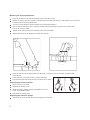
1
MIDLAND POWER
DISTRIBUTION LIMITED
qu a l i t y serv ice s u p p ort
BACK PACK BLOWER
USER’S MANUAL
MODEL: GP56BPB
www.midlandpower.co.uk
Guide to Using this Manual
Pictograms
All the pictograms attached to the machine are shown and explained in this manual.
The operating and handling instructinns are supported by illustrations.
Symbols in text
The individual steps or procedures described in the manual may be marked in different ways:
Step or procedure without direct reference to an illustration.
Description of step or procedure that refers directly to the illustration and contains item numbers that appear
in the illustration.
Example:
Loosen the screw (1)
Lever (2) ...
ln addition to the operating instructions,this manual may contain paragraphs that require your special attention.Such paragraphs are marked with the symbols described below:
Warning where there is a risk of an accident or personal injury or serious damage to property.
Warning where there is a risk of damaging the machine or individual components.
Note or hint which is not essential for using the machine, but may improve the opetator's umderstanding
of the situation and result in better use of the machine.
Note or hint on correct procedure in order to avoid damage to the environment.
Equipment and features
This instruction manual refers to several models with different features. Components that are not installed in
all models and related applications are marked thus. Such components are available as special accessories
from your dealer.
Engineering improvements
Philosophy is to continually improve all of its products. As a result, engineering changes and Tmprovements
are made from time to time. If the operating chatacteristics or the appearance of your machine differ from
those described in this manual, please contact your dealer for assistance.
Therefore, we cannot be responsible for changes, modifications or improvements not covered in this manual.
Safety Precautions
Special safety precautions must be observed when working with the power tool.
It is important that you read, fully understand and observe the following safety precautions and warnings.
1
Careless or improper use of any blower may cause serious or fatal injury.
Have your dealer show you how to operate your blow et.Observe all applicable local safety regulations,standards and ordinances.
Minors should never be allowed to use a blower.
Bystanders, especially children, and animals should not be allowed in the area where a blower is in use.
The operator is responsible for avoiding injury to third parties and damage to their property.
Do not lend or rent your blower without the owner's manual. Be sure that anyone using your blower understands the information contained in this manual.
You must be fit to work with a blower
Rested, healthy and in good physical and mental condition
If you get tired,take a break in good time
Do not operate the blower if you are under the influence of any substance (drugs, alcohol, etc.)which might impair vision, dexterity or judgment.
Only attachments supplied are expressly approved for use with your specific model are authorized.
Other attachments must not be used because of the increased risk of accidents.
Excludes all liability for personal injury and damage to property caused while using unauthorized attachments.
Wear proper clothing and equipment
Clothing must be sturdy and snug-fitting,but allow complete freedom of movement - a safety
coverall is recommended.
Avoid loose-fitting jackets,scarfs, neckties, jewelry,flared or cuffed pants,unconfined long hair
or anything that could get into the air intake.
Wear sturdy boots with nonslip soles. Steel-toed safety boots are recommended.
Wear safety glasses,goggles or a face shield.
Wear sound barriers (ear plugs or ear mufflers) to protect your hearing.
Wear heavy-duty, nonslip gloves, preferably made of chrome leather.
2
Always shut off the engine before fefueling.
Gasoline is an extremely flammable fuel. Do not smoke or bring any fire or flame near
the fuel.
Do not fuel a hot engine - fuel may spill and cause a fire.
Remove the fuel filler cap on the unit carefully so as to allow any pressure build-up in the tank to release
slowly.
Fuel your blower, in well-ventilated areas, outdoors only. Wipe off any spilled fuel before starting and check
for leakage. Take care not to get fuel on your clothing. If this happens, Change immediately.
Unit vibrations can cause an improperly tightened fuel cap to loosen or come off and spill
quantities of fuel.
In order to reduce risk of fuel spillage and fire, tighten fuel cap as speeifred.
On units with a screw cap: Tighten the cap by hand with as much force as possible. On units with hinged
handle on the fuel cap: Tighten as described in chapter "Fueling".
Check for fuel leakage while refueling and during operation. If fuel leakage is found, do not start or run the
engine until leak is fixed.
Store gasoline and oil in propetly labelled, approved safety-type cans.
Transporting the unit
Always stop the engine.
Transporting in a vehicle: Properly secure your unit to prevent turnover, fuel spillage and damage. When the
unit is not in use(work break), put it dowm so that it does not endanger others.
Before starting
Check the following points:
Throttle trigger must move freely and spring back to idle position when released.
Stop switch must move easily to"OFF"
Tightness of spark plug boot-if boot is Loose, sparks may oceur and ignite the escaping fuel vapor!
Starting
Start the engine at least 3 m (10 ft) from the fueling spot, outdoors only.
To reduce the risk of breathing toxic fumes, never start or run your unit in confined spaces.
Place the unit on firm ground in an open area.
Make sure you have good balance and secure footing.
Hold the unit securely.
Your blower is a one-person unit. Do not allow other persons to be near the running unit - even when
starting.
For specific starting instructions, see chapter"Starting" in the owner's manual.
3
During opetation
Warning!
Your blower produces toxic exhaust fumes as soon as the engine is running. These gases
(e.g. carbon monoxide ) may be colorless and odorless. To reduce the risk of serious or fatal injury from
breathing toxic fumes, never run the blower indoors or in poorly ventilated locations.
Ensure proper ventilation when working in trenches, hollows or other confined areas.
To reduce the risk of igniting highly combustible fuel vapor and causing a fire, never
smoke while working with or standing next to the blower.
Always hold your unit firmly- make sure you always have a firm and secure footing.
Examine the work area: Do not direct
the air blast towards bystanders
since the air flow can blow small objects at great speed.
Take care in slippery conditions
On ice, in wet or snow
On slopes or uneven ground
Watch out for obstacles:
Roots, ditches, holes or rubbish which
could cause your to trip or stumble.
Spraying attachment
ln the interests of the general oublic and the environment it is essential to observe all general safety
regulations when handling and using plant protection products and other chemicals.
Follow the safety precautions and instructions given by the manufacturer of the plant protection products.
Change clothing immediately if it becomes soaked with plant proteciton chemical or spay solution.
To reduce the risk of inhaling poisonous fumes from chemicals and exhaust gases, do not operate the
mistblower in confined spaces. Always wear a respirator when working in well- ventilated greenhouses, in
dense, high stands and performing any work with dangerous dusting chemicals. Be alert to the wind direction. Do not work into the wind. Walk forwards only when the unit is running.
After finishing work, drain and clean the container. Do not empty residual spray solution or flushing fluids
into waterways, gullies, sinks, drainage ditches or shafts. Dispose of properly in accordance with local
waste disposal regulations.
Always drain and clean the container before transporting the mistblower in a vehicle.
In an emergency, release the quick-action buckles, slip out of the harness and throw off the machine.
Vibrations
Prolonged use of the unit may result in vibration-induced circulation problems in the hands (whitefinger
disease).
No general recommendation can be given for the length of usage because it depends on several factors.
The period of usage is prolonged by:
4
-
Hand protection (wearing warm gloves)
-
breaks
The period of usage is shortened by:
-
Any personal tendency to suffer from poor circultaion (symptoms: frequently cold fingers, itching).
-
Low outside temperatures.
-
Gripping force (a tight grip hinders circulation).
Continual and regular users should monitor closely the condition of their hands and fingers. If any of the
above symptoms appear, seek medical advice.
Maintenance and repairs
Do not attempt any maintenance or repair work not described in your owner's manual.
Have such work performed at your service shop only.
Never modify your power tool in any way as this could result in serious injury.
Always stop the engine and disconnect the spark plug boot before doing any maintenance or
repair work or cleaning the machine.
Exception: Carburetor and idle adjustments.
Always clean dust and dirt off the machine after finishing work.
Do not service or store your unit near any fire or flame!
-
Check fuel cap regularly for leaks.
-
Use only a approved spark plug (see Specifications) and make sure it is in good condition.
-
Inspect ignition lead (insulation in good condition, secure connection).
-
To reduce the risk of fire due to ignition outside the cylinder, move the stop switch to OFF or ON
before turning the engine over on the starter with the spark plug boot removed or the spark plug
unscrewed.
-
Check condition of muffler periodically.
-
To avoid risk of fire and hearing loss, do not operate your unit if the muffler is damaged or missing.
-
Never touch a hot muffler or burn will result.
Assembing the Unit
5
Mounting the spraying attachment
Push the extension tube into the pleated hose as far as it will go.
Rotate the tube to the left (counter-clockwise) as far as stop and leave it in that position until you have
completed the following adjustments.
Turn the control handle counterclockwise to the horizontal position.
Now rotate the extension rube counterclockwise until the metering unit points in the same direction as the control handle.
Tighten down clamp screw (see "Adjusting the control handle").
Attach liquid hose to the pleated hose with the retainer .
Push the free end of the liquid hose over the stub on the stop cock and secure in position with
the hose clip .
Close the stop cock (move lever to vertical position).
Fill up with water and check all hose connections for leaks.
Adjusting the control handle
Put the unit on your back.
Release the clamp screw .
Slide the control handle along the pleated hose to the
most comfortable position.
Retinhten the clamp screw .
Adjusting the harness straps
Pull the ends of the straps downward to tighten the harness.
6
Fuel
Your engine requires a mixture of gasoline and engine oil.
The quality of these constituents and the mix ratio have a
decisive influence on the function and scervice life of the
engine.
Loosening the harness straps
Lift the tabs of the two sliding adjusters.
Adjust the straps so that the backplate is held firmly and comfortably against your back.
Unsuitable fuels or lubricants or mix ratios other than
those specified may result in serious damage to the
engine (piston seizure,rapid rate of wear, etc.).
Gasoline
Use only regular branded gasoline with a minimum octane rating or 90. lf the octane rating of the regular
grade gasoline in your area is lower, use premium fuel - leaded or unleaded.
For health and environmental reasons,you should give preference to unleaded gasoline.
If your machine is equipped with a catalytic converter, you must use unleaded gasoline.
A few tankfuls of leaded gasoline will greatly reduce the efficiency of the catalytic converter.
Engine oil
Use only quality two-stroke engine oil.
Other quality two-stroke engine oils must conform to classification TC.
Poor quality gasoline or engine oil may damage the engine, sealing rings, hoses and the fuel tank.
Mixind fuel
Avoid direct skin contact with gasoline and avoid inhaling gasoline vapour.
Use a canister approved for storing fuel. Pour oil (1) into the canister first, then add gasoline (2) and
mix thoroughly.
Mix ratio
Two-stroke engine oils (classification TC): 25 parts gasoline
to 1 part oil
Fueling
Storing fuel
Fuel mix ages:
Only mix sufficient fuel for a few months work. Store in
approved safery-type fuel canisters in a dry and safe
location.
Thoroughly shake the mixture in the canister before fueling your machine.
Pressure may build up in the canister - open it carefully.
Clean the fuel tank and canister from time to time.
Dispose of cleaning fluid properly at authorized disposal location.
7
Before fueling, clean the filler cap and the area a around it to ensure that no dirt falls into the tank.
Position the unit so that the filler cap is facing up.
Take care not to spill fuel while fueling and do not overfill the tank.
After fueling, tighten down filler cap by hand as securely as possible.
Change the fuel pickup body once every year
Drain the fuel tank.
Use a hook to pull the fuel pickup body out of the tank and take it off the hose.
Push the new pickup body into the hose.
Place the pickup body in the tank.
see "Guide to Using this Manual"
Starting / Stopping the Engine
8
Observe safety precautions - see chapter" Safety Precautions".
Slide the stop switch (1) to ON
Move the setting lever (2) to the center position - this is the starting throttle position
Note:
The setting lever can be used to select any throttle opening between idle speed (lower stop) and full
throttle (upper stop).
Set the lever to idle position before switching off the engine.
Before starting
If the engine is cold, turn the choke knob to
If the engine is warm, turn the choke lever to
Also use this position is the engine has been running
but is still cold.
Put the unit on the ground. Check that bystanders
are well clear of the general work area and the
nozzle.
Make sure you have a firm footing: Hold the unit
with your left hand on the housing and put one
foot againstthe base plate to prevent it slipping.
Pull the satarter grip slowly with your right hand
until you feel it engage and give it a brisk strong
pull. Do not pull the starter rope out all the way
as it might otherwise break.
Do not let the starter grip snap back.
9
Guide it slowly back into the housing so that the starter rope can rewind properly.
When engine begins to fire:
If engine is cold:
Turn choke knob to
engine runs.
and continue cranking until
If engine is warm:
Continue cranking until engine runs.
As soon as engine runs:
Move the setting lever (2) to the lower stop so that the
engine settles down to idle speed.
To shut down the engine:
Slide the stop switch (1) to OFF
At very low outside temperatures: Allow engine to warm
up
As soon as engine runs:
Move the setting lever to the lower stop - the engine settles down to idle speed.
Open throttle slightly - warm up engine for a short period.
If the engine does not start:
If you did not turn the choke knob to
chamber is flooded.
Pull off the spark plug boot.
Unscrew and dry off the spark plug.
10
quickly enough after the engine began to fire, the combustion
Set the stop switch to OFF
Open the throttle fully.
Pull the starter rope several times to clear the combustion chamber.
Fit the spark plug and reconnect the spark plug boot.
Move the stop switch to ON
Turn the choke knob to
even if the engine is cold.
Now start the engine.
Fuel tank run until dry and then refueled
Pull the starter rope several times to prime the fuel line.
Operating lnstructions
During break-in period
A factory new machine should not be run at high
revs (full throttle off load) for the first three tank
fillings. This avoids unnecessary high loads during
the bresk-in period. As all moving parts have to bed
in during the bresk-in period, the frictional resistances in the engine are greater during this period. The
engine develops its maximum power after about 5
to 15 tank fillings.
During operation
After a long period of full-throttle operation, allow engine to run for a while at idle speed so that the heat
in the engine can be dissipated by flow of cooling air. This protects engine- mounted components (ignition,
carburetor) from thermal overload.
After finishing work
Storing for short period:
Wait for engine to cool down. To avoid condensation, fill the fuel tank and keep the unit in a dry place until
you need it again. Storing for a long period: see chapter"Storing the Machine".
Cleaning the Air Filter
11
Dirty air filers reduce engine power increase fuel consumption and make starting more difficult.
If there is a noticeable loss of engine power
Turn choke knob to
Release the screws (1) and pull off the filter cover (2).
Remove the filter from the cover and inspect it - if it is dirty or damaged, clean the filter or fit a new
one.
Install the main filter and prefilter elements in the filter cover.
Fit the cover on the filter base and tighten it down firmly.
Carburetor
General lnformation
Your carburetor comes from the factory with a standard setting.
This setting provides an optimum fuel-air mixture under most operating conditions.
The high speed screw alters the engine's power output and the maximum off-load engine speed.
If the setting is too lean there is a risk of engine damage due to insufficient lubrication and overheating.
Standard Setting
Carburetor with limiter caps
Shut off the engine.
Screw down the high speed screw (H) and low speed
screw (L) counterclockwise as far as stop (no more
than 1/4 turn).
Carburetor without limiter caps
Shut off the engine.
Carefully screw both adjusting screws down onto
their seats (clockwise).
Open the high speed screw (H) one full turn.
Open the low speed screw (L) one full turn.
Adjusting IdIe Speed
Engine stops while idling
Carry out standard setting on low speed screw.
Turn the idle speed screw (LA) clockwise until
the engine runs smoothly.
CHOKE
Erratic idling behavior, poor acceleration
Carry out standard setting on low speed screw.
Turn low speed screw (L) counterclockwise until
the engine runs and accelerates smoothly.
It is usually necessary to change the setting of the idle
speed screw (LA) after every correction to the low speed screw (L).
12
LA
Fine Tuning for Operation at High Altitude
A slight correction of the setting may be necessary if engine power is not satisfactory when operating at
high altitude:
check the standard setting.
Warm up the engine.
Turn the high speed screw (H) slightly clockwise (leaner). On models with limiter caps, turn high speed
screw (H) 1/4 turn, but no further than stop.
If the setting is too lean there is a risk of engine damage due to insufficient lubrication and overhe
ating.
Checking the Spark Plug
If engine is down on power, difficult to start or runs poorly at idle speed first check the spark plug.
Remove the spark plug - see "Starting / Stopping the Engine"
Check electrode gap (A) and readjust if necessary - see "Specifications".
Rectify the problems which have caused fouling of spark plug:
-
To much oil in fuel mix.
-
Dirty air filter.
-
Unfavorable running conditions.
2
Fit a new spark plug after about 100 operating hours or sooner if the electrodes are badly eroded.
To reduce the risk of arcing and fire:
1
3
13
If the spark plug comes with a detachable adapter nut (1), screw it on fi rm ly.
On all spark plugs:
Always press the boot (2) firmly on to the spark plug (3).
Engine Running Behavior
If engine running behavior is unsatisfactory even though the air filter is clean and the carburetor properly
adjusted, the cause may be in the muffler.
Have the muffler checked for contamination (coking) by dealer.
Replacing Starter Rope and Rewind Spring
1
1
2
1
Replacing the starter rope
Remove the screws (1).
Take the starter cover(2) off the engine.
14
Remove the spring clip (3).
Remove the rope rotor with washer (4) and pawl (5).
Ease the cap (6) out of the starter grip.
Remove remaining rope from the rotor and grip.
Tie a simple overhand knot in the end of the new starter rope (see Specifications) and then thread the
rope through the top of the grip and the rope bush (7).
Refit the cap in the grip.
Thread the rope through the rotor and secure it in the rotor with a simple overhand knot.
5
4
3
Fit the pawl (5) in the rotor and slip the washer (4) over the starter post.
Use a screwdriver or suitable pliers to install the spring clip (3) on starter post and over the peg on the ]
pawl-the spring clip must point clock wise - see illustration.
Go to "Tensioning rewind spring".
Replacing a broken rewind spring
Lubricate the new spring with a few drops of non-resinous oil.
Remove the rope rotor as described in "Replacing the starter rope".
Remove parts of old spring.
Fit new spring housing - bottom plate must face downward. Engage outer spring loop over the lug.
Refit the rope rotor.
Go to "Tensioning rewind spring".
lf the spring pops out and uncoils during installation: Refit it in the spring housing in the counterclockwise direction - start outside and work inward.
Tensioning rewind spring
Make a loop in the unwound starter rope and use it to turn the rope rotor six full revolutions in the
direction of the arrow (see illustration).
15
Make a loop in the unwound starter rope and use it to turn
the rope rotor six full revolutions in the direction of the arrow
(see illustration).
Hold the rotor steady - .straighten the twisted rope.
Release the rotor and let go of rope slowly so that it winds
onto the rotor.
The starter grip must sit firmly in the rope guide bush. lf the
grip droops to one side: lncrease spring tension by one
additional turn.
When the starter rope is fully extended it must be possible to
rotate the rotor at least another half turn. lf this is not possible,
the spring is overtensioned and could break. Take one turn of
the rope off the rotor.
Fit the starter cover on the enging.
Tighten down the screws firmly.
Move the stop switch to OFF
Storing the Machine
For periods of about 3 months or longer
Drain and clean the fuel tank in a well ventilated area.
Drain and clean the container.
Run engine until carburetor is dry - this helps prevent carburetor diaphragms sticking together.
Thoroughly clean the machine- pay special attention to the cylinder fins and air filter.
Store the machine in a dry, high or locked location - out of the reach of children and other unauthorized
persons.
Do not expose the container to direct sunlight for unnecessarily long periods. UV rays can make the
container material brittle, which could result in leaks or breakage.
Visual inspection (conditon, leaks)
Complete machine
Control handle
Air filter
x
x
fuel tank
x
x
16
x
Clean
x
x
x
Readjust idle
Readjust electrode gap
Cooling air intakes
Clean
x
x
x
Check
x
Clean or replace
All accessible screws and nuts
(not adjusting screws)
Tighten
Container with hose
Visual inspection (condition, leaks)
Metering unit
Check
Anti-vibration elements
x
x
Replace
Spark plug
Spark arresting screen in muffler
x
Check
Check idle setting
Carburetor
Visual inspection
Have replaced by dealer
if required
x
Clean
Replace
Filter in fuel tank
if damaged
if problem
every 12 months
monthly
weekly
after each
refueling stop
x
x
Clean
Check operation
after finishing
work or daily
The following maintenance intervals apply to normal operating conditions only.
lf your daily working time is longer than normal or operating conditions are
difficult (very dusty work area etc.), shorten the specified intervals accordingly.
before
starting work
Maintenance Chart
x
x
x
x
x
x
Minimize Wear and Avoid Damage
Observing the instructions in this manual helps reduce the risk of unnecessary wear and damage to the
power tool.
The power tool must be operated, maintained and stored with the due care and attention described in this
owner's manual.
The user is responsible for all damage caused by non-observance of the safety precautions, operating and
maintenance instructions in this manual. This includes in particular:
-
Alterations or modifications to the product not approved by dealer.
-
Using attachments, Power Tool Attachments or cutting tools not approved by dealer.
-
Using the product for purposes for which it was not designed.
-
Using the product for sports or competitive events.
-
Consequential damage caused by continuing to use the product with defective components.
Maintenance Work
All the operations described in the "Maintenance Chart" must be performed on a regular basis. If these
maintenance operations cannot be performed by the owner, they should be performed by an authorized
servicing dealer.
If these operations are not carried out as specified, the user assumes responsibility for any damage that
may occur. Among other things, this includes:
- Damage to the engine due to neglect or deficient maintenance (e.g. of air and fuel filters), incorrect
carburetor adjustment or inadequate cleaning of cooling air inlets (intake ports, cylinder fins).
-
Corrosion and other consequential damage resulting from improper storage.
-
Damage and consequential damage resulting from the use of parts other than original replacement parts.
-
Damage resulting from maintenance or repair work performed by authorized servicing dealers.
Parts Subject to Wear and Tear
Some parts of the power tool are subject to normal wear and tear even during regular operation in accordance
with instructions and, depending on the type and duration of use, have to be replaced in good time.
Among other parts, this includes:
-
Filters (air, fuel)
-
Fanwheel
-
Starter mechanism
-
Spark plug
-
Components of anti-vibration system
17
Specifications
Ignition System
Single cylinder two-stroke engine
Displacement:
56.5 cm
Bore:
46 mm
Type:
3
Spark plug
(suppressed):
Stroke:
34 mm
Idle speed:
2.800 rpm
Engine power:
2.5 kw
Weight:
10.5 kg
Ari flow rate:
1060 m /h
Electrode gap:
Spark plug thread:
3
Spraying attachment
Fuel System
Container capacity: 141
Size of filler strainer 1 mm
mesh:
Discharge rate
0.14-3.03 l/min
(infinitely)
variable)
Quantity left in
0.1 l
container:
(design related)
Carburetor:
Rewind Starter
Starter rope:
3.5 mm dia.
x 960 mm
1) Weighted equivalent level includes
idling and racing with the same
duration of exposure
18
Electronic
magneto ignition
Bosch WSE 6 F
or
BPMR 7 A;
0.5 mm
M 14 x 1.25;
9.5 mm long
Air filter:
Fuel tank capacity:
Fuel mix:
All position
diaphragm
carburetor with
integral fuel
pump
Sponge element
1.8
see chapter
"Fuel"