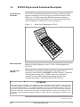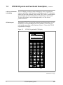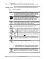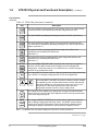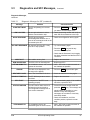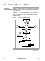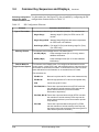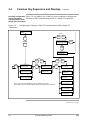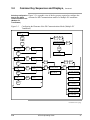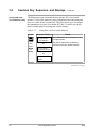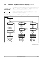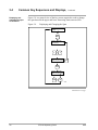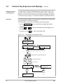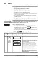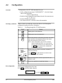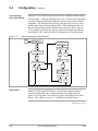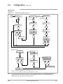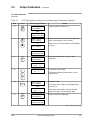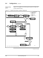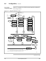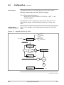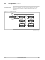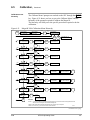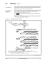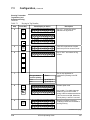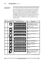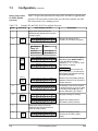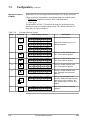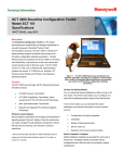
1
Smart Field Communicator Model STS103 Operating Guide 34-ST-11-14F 4/99 Copyright, Notices, and Trademarks © Copyright 1995 by Honeywell Inc. Revision F – 4/99 While this information is presented in good faith and believed to be accurate, Honeywell disclaims the implied warranties of merchantability and fitness for a particular purpose and makes no express warranties except as may be stated in its written agreement with and for its customer. In no event is Honeywell liable to anyone for any indirect, special, or consequential damages. The information and specifications in this document are subject to change without notice. This document was prepared using Information Mapping® methodologies and formatting principles. Information Mapping® is a registered trademark of Information Mapping, Inc. ST 3000 and SFC are U.S. registered trademarks of Honeywell Inc. Honeywell Industrial Automation and Control Automation College 2820 West Kelton Lane Phoenix, Arizona 85023 ii STS103 Operating Guide 4/99 About This Publication This manual provides operating instructions for the STS103. The operating instructions cover the use of the SFC with the Smart Pressure Transmitter ST 3000, the Smart Temperature Transmitter STT 3000 Models STT350, STT25D, STT25M, STT302 and STT300, the Magnetic Flowmeter MagneW 3000, and the Smart Multivariable Transmitter SMV 3000. The operating instructions for using the SFC with the SCM 3000 Smart Coriolis Mass Flowmeter, the SGC 3000 Smart Gas Chromatograph, and the Model STT350, STT 3000 Smart Temperature Transmitter are presented in the User’s Manual for that specific instrument. Chapters 1, 2, and 3, in this manual, contain information relating to the common information for the SFC. The specific operating information for using the SFC with ST 3000, STT 3000, MagneW 3000, and SMV 3000 is contained in separate chapters in this manual. The format of this manual is completely different than the STS102 Operating Guide. The key sequences are graphically laid out to aid you in learning how to use the SFC for the first time, as well as reminding experienced users how to perform operations you have not done in a while. The format of this manual is designed to make finding, reading, and understanding the information presented easier than ever before. 4/99 STS103 Operating Guide iii iv STS103 Operating Guide 4/99 Table of Contents SECTION 1 – SMART FIELD COMMUNICATOR STS103 OVERVIEW........................... 1 1.1 1.2 1.3 1.4 Introduction .................................................................................................. 1 STS103 Physical and Functional Description .............................................. 3 Connections ................................................................................................. 9 STS103/SFI Communication...................................................................... 10 SECTION 2– STS103 INSTALLATION............................................................................ 13 2.1 2.2 2.3 2.4 2.5 2.6 2.7 STS103 Overview ...................................................................................... 13 Keypad Functions....................................................................................... 14 Display Functions ....................................................................................... 15 Prompt Character Definitions ..................................................................... 16 Function Keys Data Entry........................................................................... 17 Configuration Key Data Entry..................................................................... 19 Other Key Sequences ................................................................................ 21 SECTION 3 – STS103 OPERATION................................................................................ 23 3.1 3.2 3.3 3.4 3.5 3.6 Overview .................................................................................................... 23 Power Up ................................................................................................... 24 Diagnostics and SFC Messages ................................................................ 25 Common Key Sequences and Displays ..................................................... 28 Using the Transmitter as a Current Source................................................ 43 Disconnecting the SFI ................................................................................ 45 SECTION 4 – ST 3000 PRESSURE TRANSMITTER...................................................... 47 4.1 4.2 4.3 4.4 4.5 4.6 4.7 4.8 Overview .................................................................................................... 47 Wiring ......................................................................................................... 48 Set-up......................................................................................................... 50 Configuration.............................................................................................. 62 Output Calibration ...................................................................................... 64 Operation ................................................................................................... 67 Diagnostics and SFC Messages ................................................................ 71 Troubleshooting ......................................................................................... 75 SECTION 5 – STT 3000 TEMPERATURE TRANSMITTER ............................................ 77 5.1 5.2 5.3 5.4 5.5 5.6 5.7 5.8 Overview .................................................................................................... 77 Wiring ......................................................................................................... 78 Set-up......................................................................................................... 80 Configuration.............................................................................................. 93 Output Calibration .................................................................................... 102 Operation ................................................................................................. 105 Diagnostics and SFC Messages .............................................................. 109 Troubleshooting ....................................................................................... 114 SECTION 6 –MAGNEW 3000 ELECTROMAGNETIC FLOWMETER .......................... 115 6.1 6.2 6.3 6.4 6.5 6.6 6.7 6.8 4/99 Overview .................................................................................................. 115 Wiring ....................................................................................................... 116 Set-up....................................................................................................... 118 Configuration............................................................................................ 129 Calibration ................................................................................................ 154 Operation ................................................................................................. 167 Diagnostics and SFC Messages .............................................................. 171 Troubleshooting ....................................................................................... 175 STS103 Operating Guide v Table of Contents SECTION 7 –SMV 3000 MULTIVARIABLE TRANSMITTER ........................................ 177 7.1 7.2 7.3 7.4 7.5 7.6 7.7 vi Overview................................................................................................... 177 Wiring........................................................................................................ 178 Configuration ............................................................................................ 180 Output Calibration..................................................................................... 235 Operation .................................................................................................. 239 Diagnostics and SFC Messages............................................................... 244 Troubleshooting ........................................................................................ 253 STS103 Operating Guide 4/99 Figures Figure 1-1 Figure 1-2 Figure 1-3 Figure 1-4 Figure 1-5 Figure 1-6 Figure 1-7 Figure 2-1 Figure 3-1 Figure 3-2 Figure 3-3 Figure 3-4 Figure 3-5 Figure 3-6 Figure 3-7 Figure 3-8 Figure 3-9 Figure 3-10 Figure 3-11 Figure 3-12 Figure 3-13 Figure 3-14 Figure 3-15 Figure 3-16 Figure 4-1 Figure 4-2 Figure 4-3 Figure 4-4 Figure 4-5 Figure 4-6 Figure 4-7 Figure 4-8 Figure 4-9 Figure 5-1 Figure 5-2 Figure 5-3 Figure 5-4 Figure 5-5 Figure 5-6 Figure 5-7 Figure 5-8 Figure 5-9 Figure 5-10 Figure 5-11 Figure 5-12 Figure 5-13 Figure 5-14 Figure 5-15 Figure 6-1 Figure 6-2 Figure 6-3 4/99 Smart Field Communicator STS103 ......................................................... 3 STS103 Keypad and LCD Display............................................................ 4 STS103 Switch and Terminals.................................................................. 7 STS103 Battery Pack................................................................................ 8 STS103 –Junction Box ............................................................................. 9 Typical Analog Data Exchange ............................................................... 11 Typical Digital Data Exchange ................................................................ 12 STS103 Keypad Color Groups ............................................................... 14 Power Up Sequence ............................................................................... 24 Read Digital Database ............................................................................ 24 Changing Communications Mode........................................................... 28 Configuring the Elements of the DE Communications Mode (Single PV Transmitter)........................................................................... 30 Configuring the Elements of the DE Communications Mode (Multiple PV Transmitter) ........................................................................ 31 Adjusting the Damping Time Value......................................................... 33 Displaying, Setting, and Calibrating the Lower Range Value.................. 34 Displaying, Setting, and Calibrating the Upper Range Value.................. 35 Displaying and Changing the Span......................................................... 36 Displaying and Changing the Upper Range Limit ................................... 37 Corrects Reset ........................................................................................ 38 Displaying, Setting, and Clearing the Current Output. ............................ 39 Displaying and calibrating the Current Input Value ................................. 40 Displaying the SFI Diagnostic Status ...................................................... 41 Software Version..................................................................................... 41 Writing Data in Scratch Pad Area ........................................................... 42 STS103 – Junction Box and IS Connection ............................................ 48 STS103–ST 3000 Connections .............................................................. 49 Adjusting the ST 3000 Damping Time Value .......................................... 53 Changing the ST 3000 Communications Mode ...................................... 55 Configuring the ST 3000 DE Communications Mode ............................. 57 Changing the ST 3000 Lower Range Value (LRV) ................................. 58 Changing the ST 3000 Upper Range Value (URV) ................................ 59 Configuring the ST 3000 Transmitter...................................................... 63 ST 3000 Troubleshooting Procedure ...................................................... 75 STS103 – Junction Box and IS Connection ............................................ 78 STS103 Connections to Model STT350 Transmitter .............................. 79 STS103 Connections to Model STT25D and STT25M Transmitters ...... 79 STS103 Connections to Model STT300 and STT302 Transmitters........ 80 Adjusting the STT 3000 Damping Time Value........................................ 84 Changing the STT 3000 Communications Mode .................................... 86 Configuring the STT 3000 DE Communications Mode ........................... 88 Changing the STT 3000 Lower Range Value (LRV)............................... 89 Changing the STT 3000 Upper Range Value (URV) .............................. 90 STT 3000 Temperature Transmitter Configuration ................................. 94 STT 3000 Probe Configuration ............................................................... 98 Save/Restore Data.................................................................................. 99 Alarm Latching/Open Input Failsafe...................................................... 100 Write Protect and Password ................................................................. 101 STT 3000 Troubleshooting Procedure.................................................. 114 STS103 – Junction Box and IS Connection .......................................... 116 STS103–MagneW Connections............................................................ 117 Adjusting the MagneW 3000 Damping Time Value .............................. 122 STS103 Operating Guide vii Figures Figure 6-4 Figure 6-5 Figure 6-6 Figure 6-7 Figure 6-8 Figure 6-9 Figure 6-10 Figure 6-11 Figure 6-12 Figure 6-13 Figure 6-14 Figure 6-15 Figure 6-16 Figure 6-17 Figure 6-18 Figure 6-19 Figure 6-20 Figure 6-21 Figure 6-22 Figure 6-23 Figure 6-24 Figure 6-25 Figure 6-26 Figure 7-1 Figure 7-2 viii Selecting the MagneW 3000 Units in which to Display Values.............. 124 Changing Communications Mode ......................................................... 125 Configuring the MagneW 3000 DE Communications Mode .................. 127 Changing the MagneW 3000 Upper Range Value (Span) .................... 128 MagneW 3000 Prompt hierarchy........................................................... 130 MagneW 3000 Units Key Configuration ................................................ 132 MagneW 3000 Range Configuration Graphic........................................ 137 MagneW 3000 Detector Data Configuration.......................................... 139 MagneW 3000 Alarm Setting Configuration .......................................... 141 MagneW 3000 Failsafe Condition Configuration ................................... 143 MagneW 3000 Digital Input/Output Configuration ................................. 145 MagneW 3000 Totalizer Menu Hierarchy .............................................. 147 MagneW 3000 Pulse Output Configuration ........................................... 148 MagneW 3000 Pulse Config?................................................................ 150 MagneW 3000 Set Trip Value ............................................................... 151 Save/Restore Data ................................................................................ 152 MagneW 3000 Calibration Set-up ......................................................... 155 MagneW 3000 Calibration Menu Hierarchy........................................... 161 MagneW 3000 Excitation Current Check .............................................. 162 MagneW 3000 Excitation Current Calibration ....................................... 164 MagneW 3000 Gain Calibration ............................................................ 165 MagneW 3000 DI/DO Check ................................................................. 166 MagneW 3000 Troubleshooting Procedure........................................... 175 STS103 – Junction Box and IS Connection ........................................... 178 STS103–SMV 3000 Connections .......................................................... 179 STS103 Operating Guide 4/99 Tables Table 1-1 Table 1-2 Table 1-3 Table 1-4 Table 2-1 Table 2-2 Table 2-3 Table 2-4 Table 2-5 Table 2-6 Table 3-1 Table 3-2 Table 3-3 Table 3-4 Table 3-5 Table 4-1 Table 4-2 Table 4-3 Table 4-4 Table 4-5 Table 4-6 Table 4-7 Table 4-8 Table 4-9 Table 5-1 Table 5-2 Table 5-3 Table 5-4 Table 5-5 Table 5-6 Table 5-7 Table 5-8 Table 5-9 Table 5-10 Table 5-11 Table 6-1 Table 6-2 Table 6-3 Table 6-4 Table 6-5 Table 6-6 Table 6-7 Table 6-8 Table 6-9 Table 6-10 Table 6-11 Table 6-12 Table 6-13 Table 6-14 Table 6-15 Table 6-16 Table 6-17 Table 6-18 Table 6-19 4/99 Model STS103 Specifications ................................................................... 2 STS103 Key Functions ............................................................................. 5 Communication Format Description........................................................ 10 Typical Digital Data Exchange Sequence of Events ............................... 12 STS103 Key Color Group Description .................................................... 14 LCD Display Functions ........................................................................... 15 STS103 LCD Character Definitions and General Rules ......................... 16 Function Key Sequence.......................................................................... 18 Configuration Key Sequence .................................................................. 19 Other Key Sequences............................................................................. 21 Diagnostic Messages for SFC ................................................................ 26 DE Configuration Elements..................................................................... 29 Storing Data in Non-volatile memory ...................................................... 32 Using the SFI as a Constant Current-source .......................................... 44 Disconnect Check List............................................................................. 45 Keying–in the ST 3000 ID and Uploading the Database ........................ 50 Selecting the ST 3000 Units ................................................................... 54 The ST 3000 DE Configuration Elements............................................... 56 Setting the ST 3000 Lower Range Value Using Applied Pressure ......... 60 Setting the ST 3000 Upper Range Value Using Applied Pressure ......... 61 Scrolling through the ST 3000 Parameters............................................. 62 ST 3000 Digital to Analog Current Output Signal Calibration ................. 64 ST 3000 Operating Data ......................................................................... 68 Diagnostic Messages for SFC and ST 3000........................................... 72 Keying–in the STT 3000 ID and Database ............................................. 81 Selecting the STT 3000 Units ................................................................. 85 STT 3000 DE Configuration Elements.................................................... 87 Setting the STT 3000 Lower Range Value Using Applied Temperature. 91 Setting the STT 3000 Upper Range Value Using Applied Temperature. 92 Scrolling through the STT 3000 Parameters........................................... 93 STT 3000 Probe Configuration Elements ............................................... 95 STT 3000 Probe Types and Ranges ...................................................... 97 STT 3000 Digital to Analog Current Output Signal Calibration ............. 102 STT 3000 Operating Data..................................................................... 106 Diagnostic Messages for SFC and STT 3000....................................... 110 Keying–in the MagneW 3000 ID and Upload Database Procedure...... 118 List of the MagneW 3000 Units by Application...................................... 123 MagneW 3000 DE Configuration Elements .......................................... 126 Scrolling through the MagneW 3000 Parameters ................................. 131 MagneW 3000 Range Config? Elements.............................................. 133 Ranging Function Definitions ................................................................ 134 Function Selection Combinations.......................................................... 136 MagneW 3000 Detector Config? Elements........................................... 138 MagneW 3000 Alarm Config? Elements............................................... 140 MagneW 3000 Failsafe Config? Elements............................................ 142 MagneW 3000 Digital I/O? Elements.................................................... 144 MagneW 3000 Totalizer Menu Elements.............................................. 146 MagneW 3000 Pulse Configure? Elements .......................................... 149 MagneW 3000 Calibration Set-up Procedure ....................................... 156 Set the MagneW 3000 Units to m/sec .................................................. 157 Set the MagneW 3000 Span to 10.001 m/sec ...................................... 158 MagneW 3000 Digital to Analog Current Output Signal Calibration ..... 159 MagneW 3000 Operating Data ............................................................. 168 Diagnostic Messages for SFC and MagneW 3000 ............................... 172 STS103 Operating Guide ix Tables Table 7-1 Table 7-2 Table 7-3 Table 7-4 Table 7-5 Table 7-6 Table 7-7 Table 7-8 Table 7-9 Table 7-10 Table 7-11 Table 7-12 Table 7-13 Table 7-14 Table 7-15 Table 7-16 Table 7-17 Table 7-18 Table 7-19 Table 7-20 Table 7-21 Table 7-22 Table 7-23 Table 7-24 Table 7-25 Table 7-26 Table 7-27 Table 7-28 Table 7-29 Table 7-30 Table 7-31 Table 7-32 Table 7-33 Table 7-34 x Keying-in Tag Number........................................................................... 182 Selecting Output Conformity.................................................................. 184 Adjusting Damping Time ....................................................................... 185 Selecting Engineering Units for PV1 and PV2....................................... 188 Selecting Engineering Units for PV3, etc............................................... 189 Selecting Engineering Units for PV4 ..................................................... 191 Selecting Engineering Units for Design Density for PV4 ....................... 192 Identifying PV3 Probe Type................................................................... 193 Selecting Source of CJ Compensation.................................................. 195 Selecting Input Filter Frequency............................................................ 196 Activating Sensor Fault Detection ......................................................... 198 Selecting Output Characterization......................................................... 199 Setting selections for PV4 Equation Definition ...................................... 205 Setting Parameters for PV4 Equation.................................................... 211 Setting Low and High Limits for Low Flow Cutoff .................................. 214 Selecting PV to Represent Analog Output ............................................ 215 Keying in LRV and URV for PV1 ........................................................... 217 Setting LRV and URV for PV1 to Applied Pressures............................. 218 Keying in LRV and URV for PV2 ........................................................... 220 Setting LRV and URV for PV2 to Applied Pressures............................. 222 Keying in LRV and URV for PV3 ........................................................... 224 Setting LRV and URV for PV3 to Applied Input Signals ........................ 225 Setting URL for PV4 .............................................................................. 228 Keying in LRV and URV for PV4 ........................................................... 229 Selecting PVs for Broadcast.................................................................. 232 Selecting Message Format.................................................................... 234 Calibrating Output Signal for Transmitter in Analog Mode .................... 235 ST 3000 Operating Data ....................................................................... 240 Critical Status Diagnostic Message Table................................................... 245 Non-Critical Status Diagnostic Message Table ..................................... 247 Communication Status Message Table................................................. 250 Informational Status Message Table ..................................................... 251 SFC Diagnostic Message Table ............................................................ 252 Accessing SMV 3000 Diagnostic Information using the SFC ................ 253 STS103 Operating Guide 4/99 Acronyms AP ............................................................................................................ Absolute Pressure DAC ............................................................................................................ Digital to Analog DE ....................................................................................................Digital Communications DI/DO ...........................................................................................Digital Input/Digital Output DP .........................................................................................................Differential Pressure DR...................................................................................................................... Dual Range DVM ............................................................................................................ Digital Voltmeter GND .......................................................................................................................... Ground GP............................................................................................................... Gauge Pressure I/O ......................................................................................................................Input/Output LCD..................................................................................................... Liquid Crystal Display PV .............................................................................................................. Process Variable SFC.............................................................................................Smart Field Communicator SFI .................................................................................................... Smart Field Instrument SR ....................................................................................................................Single Range Parameters BRL/P......................................................................................................... Barrels per pulse CC/P ......................................................................................... Cubic centimeters per pulse DAMP............................................................................................................ Damping value EU ..............................................................................................................Engineering units F/S DIR ......................................................................................................Failsafe Direction G/cm .......................................................................................Grams per square centimeter Gal/P ......................................................................................................... Gallons per pulse I/P..................................................................................................................Liters per pulse ID ..................................................................................................................Transmitter I.D. inHg...........................................................................................................Inches of mercury Kg/cm ................................................................................ Kilograms per square centimeter Kgal/P................................................................................................... Kilogallons per pulse KPa ..................................................................................................................... Kilopascals LIN .............................................................................................................................. Linear LRV ........................................................................................................Lower Range Value mBAR......................................................................................................................... Millibar mGAL/P ............................................................................................. 10-3 gallons per pulse mH2O............................................................................................................ Inches of water mH2O............................................................................................................Meters of water mmH2O.................................................................................................. Millimeters of water mmHg ................................................................................................ Millimeters of mercury MPa.................................................................................................................. Megapascals NVM ..................................................................................................... Non-volatile memory PSI .................................................................................................. Pounds per square inch SQRT ................................................................................................................ Square Root SWVER ........................................................................................ Software Version Number URL......................................................................................................... Upper Range Limit URV .......................................................................................................Upper Range Value 4/99 STS103 Operating Guide xi References Publication Title Publication Number SFC Information Card 34-ST-10-01 ST 3000 User’s Manual (for Series 100e and Series 900 Transmitters) 34-ST-25-11 ST 3000 User’s Manual (for Release 300 Transmitters) 34-ST-25-14 ST 3000 Operating Card 34-ST-11-15 STT 3000 User’s Manual (Model STT350) 34-ST-25-12 STT 3000 Series STT250 Operator Manual EN1I-6190 STT 3000 Operating Card 34-ST-11-16 MagneW 3000 User’s Manual 36-KI-25-01 MagneW 3000 Operating Card 34-ST-11-17 SCM 3000 Smart Coriolis Mass Flowmeter User’s Manual 34-CM-25-01 SGC 3000 Smart Gas Chromatograph User’s Manual 34-GC-25-01 SMV 3000 Smart Multivariable Transmitter User’s Manual 34-SM-25-02 xii STS103 Operating Guide 4/99 Section 1 —Smart Field Communicator STS103 Overview 1.1 Introduction Function The hand-held Smart Field Communicator(SFC), Model STS103 is a battery-powered device which establishes two-way communications between Honeywell’s Smart Field Instruments (SFIs) and an operator over the existing SFI signal lines. The operator can send data to and receive data from the SFI’s microprocessor, through the STS103, when connected to the SFI’s signal lines at any accessible location from the control room to the Smart Field Instrument. Smart Field Instruments (SFIs) There are many current SFIs with which the STS103 communicates. The STS103 is designed for expansion and will be used with other new SFIs as they become available. The current Honeywell smart field instruments with which the STS103 may be used are listed below. • Smart Pressure Transmitter ST 3000, • Smart Temperature Transmitter STT 3000, • Magnetic Mass Flowmeter MagneW 3000, • Smart Coriolis Mass Flowmeter SCM 3000, • Smart Gas Chromatograph SGC 3000, and • Smart Multivariable Transmitter SMV 3000. ATTENTION Operation The specific instructions for using the SFC with SCM 3000, and SGC 3000 are contained in User’s Manual for that specific instrument. You can use the STS103 to • Select the Communications Mode – Command the SFI to transmit its output signal in either an Analog (4-20 mA) mode or in the Digital Communications (DE) mode. • Configure – Enter the desired operating parameters (For example: LRV, URV, Damping, Failsafe Mode, Configuration Parameters) into the Smart Field Instrument. • Diagnose – Access the SFI self-diagnostic capabilities to troubleshoot suspected operation or communication problems. • Calibrate – The SFC provides a simplified procedure for calibrating Smart Field Instruments, thus maintaining excellent accuracy with significantly reduced maintenance requirements. • Display – Readout all the configured operating parameters from the SFI as well as other data such as PROM Serial Number, Device ID, Scratch pad memory, Sensor Temperature, Input values in selected Engineering Units, and others. Continued on next page 4/99 STS103 Operating Guide 1 1.1 Introduction, Continued Operation, continued • Specifications The STS103’s specifications are listed in Table 1-1. Table 1-1 Checkout – Put the SFI in the Output mode and command the SFI to transmit a precise signal, selectable from 0% to 100% full scale, to assist you in verifying loop operation, loop calibration, or troubleshooting. Model STS103 Specifications Operating Conditions Ambient Temperature Humidity °C °F % Vibration Maximum Acceleration (G) Frequency (Hz) Amplitude (mm peak to peak) Operating Limits Transportation and Storage –10° to 50° 14° to 122° –20° to 60° –4° to 140° 10% to 90% RH 5% to 95% RH 0.2 0 to 100 0.75 0.5 0 to 100 ----- 5 50 15 11 Shock Maximum Acceleration (G) Duration (ms) Minimum load resistance @ 24 Vdc Supply Voltage 250 Ohms Performance Safety Approvals FM Intrinsic Safe, Class I, II, III, Div 1, GP A-G Outdoor Nonincendive, Class I, Div 2, GP A-G Outdoor CE Conformity, Europe 89/336/EEC, the EMC Directive Physical Dimensions Overall Keypad 102 mm x 42 mm x 206 mm (4 In. x 1.7 in. x 8 in.) 86 mm x 136 mm (3.4 x 5.4 in.) Weight 470 g (1 lb.) LCD Display Display Character 2 lines x 16 characters 5 x 7 dots with line for cursor Keyboard Type Tactile feedback embossed membrane, 4 by 8 matrix, 32 keys Lead Connectors Easy hook and alligator clips Battery Charger Input Power Output Power Time to charge Time between charges 2 108 – 120 Vac, 200 – 240 Vac, 50/60 Hz 7 Vdc, 180 mA 16 hours minimum 24 hours minimum, a colon”:” in the eighth character position indicates low battery power. STS103 Operating Guide 4/99 1.2 STS103 Physical and Functional Description STS103 physical description The STS103 is a hand-held unit that has a 2-line by 16-character digital liquid crystal display (LCD) and a keypad. The STS103 connects to the SFI by way of a cable connected to the SFI junction box terminals. A NiCd battery pack allows the STS103 to be used in the field without the need for input power. The STS103 is shown in Figure 1-1. Figure 1-1 Smart Field Communicator STS103 ell eyw Hon . . G.. o KIN G N OR TAFC W S ITS UN MP DA NF CO ID V LR % 0 XT NE T SE V UR % 100 NU ME M IT E TOU T PU EV PR RCO CT RE 9 8 7 6 5 3 4 2 1 AT ST . 0 AN SP +/ R TE EN ES) (Y R CL O) (N T IF SH M/ NU HA P AL 20330 EMC classification Industrial Control Equipment, Group 1, Class A, ISM Equipment (ref. EN 55011). CE Conformity (Europe) This product is in conformity with the protection requirements of European Council Directive 89/336/EEC, the EMC Directive. Conformity of this product with any other “CE Mark” Directive(s) shall not be assumed. Deviation from the operating conditions specified may invalidate this product’s conformity with the EMC Directive. ATTENTION The emission limits of EN 50081-2 are designed to provide reasonable protection against harmful interference when this equipment is operated in an industrial environment. Operation of this equipment in a residential area may cause harmful interference. This equipment generates, uses, and can radiate radio frequency energy and may cause interference to radio and television reception when the equipment is used closer than 30 meters (98 feet) to the antenna(e). In special cases, when highly susceptible apparatus is used in close proximity, the user may have to employ additional mitigating measures to further reduce the electromagnetic emissions of this equipment. Continued on next page 4/99 STS103 Operating Guide 3 1.2 STS103 Physical and Functional Description, Continued 2-line by 16-character LCD display The LCD display provides prompts and displays values, keypad input, statuses, and alarms. Each character on the display is in a 5 X 7 dot matrix with a line below the character for the cursor. The STS103 is multi-lingual and can display parameters and statuses in engineering or metric units. The desired language is selected through menus, as is the desired parameter format. STS103 keypad Through the STS103’s keypad, the parameters and characteristics of each SFI may be viewed and changed. In several instances, several keys are used together to perform certain functions. Figure 1-2 shows the STS103 keypad and LCD display. Figure 1-2 STS103 Keypad and LCD Display L ABCDEFGHIJKLMNOPQR ABCDEFGHIJKLMNOP QRSTUVWXYZ012345 STUVWXYZ1234567890 DE READ A ID B CONF C DAMP E LRV 0% F URV 100% G SET DE CONF I MENU ITEM INPUT J OUTPUT RESET K CORRECT M A <–> DE Q 7 4 F/S DIR U STAT 1 URL Y SPAN 0 N R V 8 5 O S W 2 SCR PAD Z D UNITS H NEXT L PREV 9 6 P T SW VER X 3 +– NON-VOL NUM / ALPHA SHIFT CLR (NO) ENTER (YES) 20720 Continued on next page 4 STS103 Operating Guide 4/99 1.2 STS103 Physical and Functional Description, STS103 key functions Continued Table 1-2 describes the use and function of the STS103 keypad keys. Table 1-2 STS103 Key Functions Key NUM / ALPHA ^ SH I F T CLR (NO) NON-VOL ENTER (YES) Function The white NUM/ALPHA key toggles between the alpha mode or numeric mode for the STS103. In the alpha mode, the capital letter or character in the upper right-hand corner of the keys is input when that key is pressed. In the numeric mode, the number is input or the indicated first function is performed. The black SHIFT key enables the second function above certain keys to be performed. When shifted functions are enabled, the word “SHIFT–” is displayed on line two of the display. The second function desired must be selected immediately after the Shift key is pressed. The Shift key upper right-hand character, the caret character, is input when in the alpha mode. The white CLR (NO) key cancels the current function or task when pressed and backs out to its previous operating state. The NO, or negative response, function is used in response to questions in the LCD display or decisions. The orange ENTER (YES) (NON-VOL) key is used to send a write/set command to the RAM memory in an SFI or to answer “Yes” to prompts. The NON-VOL second function writes data into the non-volatile memory of an SFI. DE READ A ID Z 0 Z P 0 SCR PAD + 9 The Alpha keys A – Z input the alpha character in the upper righthand corner when the alpha mode is activated. The alpha mode is available to enter an ID name or to use the Scratch Pad. The cursor is replaced by a “*” character when the alpha mode is activated. The yellow Numeric keys 0 – 9 input the number character when the number mode is activated. When in the numeric mode, the cursor is shown as a blinking . The yellow decimal point (SCR PAD) key inputs a decimal point when in the number mode and a space in the alpha mode. The SCR PAD second function displays data in the SFI’s scratch pad memory. The yellow positive/negative key functions as follows: – DE READ A ID • When entering an ID name or using the Scratch Pad function, the ALPHA/NUM key toggles to allow a (–) hyphen (NUM mode) or a (/) slash (ALPHA mode) to be entered using the +/– key. • In the configuration mode, use the +/– key to enter a positive or negative symbol when entering a value. The NUM/ALPHA key toggles between “+” and “–”. The green ID (DE READ) key reads and displays the device’s tag name (ID) when pressed. In analog devices, the database is also read. The DE READ second function reads the digital enhanced SFI’s database along with the tag name. Continued on next page 4/99 STS103 Operating Guide 5 1.2 STS103 Physical and Functional Description, Continued Key functions, continued Table 1-2 STS103 Key Functions (Continued) Key Description B CONF The green CONF key starts each SFI’s configuration mode. The unique settings are the parameters and characteristics that are configured into the SFI. C DAMP The green DAMP key displays the damping constant of the SFI. (See Note 1.) D UNITS The green UNITS key displays the SFI’s currently selected engineering units. The units may be changed by repeatedly pressing the key until the desired units appear. (See Note 1.) LRV 0% The green LRV 0% key displays the SFI lower range value (LRV) in the engineering unit selected by the UNITS Key. (See Note 1.) F URV 100% The green URV 100% key displays the SFI upper range value (URV) in the engineering unit selected by the UNITS key. (See Note 1.) E DE CONF I MENU ITEM G SET The green MENU ITEM (DE CONF) key selects the current PV from multi-PV devices. The DE CONF second function displays the current Digital (DE) configuration. Allows the selection of one data item from a series of grouped functions in the configuration mode. The orange SET key sets the function of the key pressed immediately before this key in the SFI. For example, setting the URV or LRV to the applied PV. H L NEXT PREV The orange NEXT and PREV keys set the damping constant, change the engineering units, increase and decrease numeric values during output D/A calibrations, and displays the next/previous units in the unit selection. These keys also select the next or previous configuration element in an SFI’s unique setting mode. INPUT J OUTPUT The orange OUTPUT (INPUT) key displays the currently selected transmitted output in percent. The second function displays the SFI’s currently selected input in the active engineering units. RESET K CORRECT The orange CORRECT (RESET) key is used to make on-line zero corrections and to calibrate output signal and range values. The RESET second function returns the ST and STT transmitters to their original factory calibration states. Resetting the MagneW transmitter is done through the calibration menus. Note 1. For Multi-PV SFI’s, the STS103 displays the value for the currently selected PV. Continued on next page 6 STS103 Operating Guide 4/99 1.2 STS103 Physical and Functional Description, Continued Key functions, continued Table 1-2 STS103 Key Functions (Continued) Key M F/S DIR U STAT Description A <–> DE Q The olive cursor keys move the cursor forward or backward one position while the cursor is displayed. In the number mode, the cursor back key performs a backspace function. The A <–> DE second function of the cursor back key toggles the SFI output mode between analog and digital enhanced communication. The olive STAT (F/S DIR) key sequentially displays the result of an SFI’s diagnostics. The second function displays the failsafe direction, Hi or Lo, for analog SFIs. The failsafe direction is hard-wired in the analog SFI and determines the direction the SFI output goes in burnout (SFI failure). URL Y SPAN The olive SPAN (URL) key displays the span in Engineering units selected by the UNITS key. The second function displays the upper range limit (URL) value of the SFI. SW VER X The yellow 3 (SW VER) key second function displays the software version of the STS103 when not communicating with an SFI, or the software versions of the STS103 and SFI when connected to an SFI. 3 STS103 switch and terminals Figure 1-3 shows the STS103 ON/OFF switch and the terminals on the sides of the unit. Figure 1-3 STS103 Switch and Terminals Charging Terminal ON/OFF Switch Left Side Communications Terminal Right Side 20721 Continued on next page 4/99 STS103 Operating Guide 7 1.2 STS103 Physical and Functional Description, Battery pack location Figure 1-4 Continued The battery pack is located behind the LCD display and is accessed through a back panel. Two hex screws need to be removed to access the battery pack. Figure 1-4 shows the location of the battery pack and how it fits into the STS103. STS103 Battery Pack 20722 Charging the batteries The battery pack is charged by plugging the battery charger into an outlet and inserting the lead into the charging terminal of the STS103. The battery pack takes a minimum of 10 hours to charge and the STS103 may be used continuously for up to 24 hours before the battery pack needs recharging. A colon (:) will be appear in the middle of the top line on the LCD display when the battery pack needs charging. STS103 charging terminal The battery pack is charged through a battery charger that plugs into the charging terminal. The charger inputs 110 or 220 Vac 50/60 Hz and outputs 7 Vdc 180 mA to the NiCd battery pack. The connector of the battery charger is inserted into the charging terminal on left side of the STS103 by the ON/OFF switch. Self-diagnostics When the STS103 is turned on, it automatically runs diagnostics on its functions. Upon successful completion of the diagnostics, the message, “PUT LOOP IN MAN” (analog communications) or “DE-XMTR PRESS ID” (digital communications) appears. If an error occurs, the message, “CRITICAL STATUS” appears. Refer to Section 3 for a description of the STS103 errors or the individual device sections for device specific error messages. 8 STS103 Operating Guide 4/99 1.3 Connections Connecting the STS103 to junction boxes and IS panels The STS103 connects to SFIs, IS panels, and junction boxes through a pair of wires with alligator clips on the ends. The STS103 communications terminal end of the wires has a stereo phone jack connection that is inserted into the communications terminal. The other end of the wires are clipped onto terminals in the junction box or IS barrier panel, or directly to the transmitter. The red SFC lead connects to the junction box or SFI positive terminal, the black lead to the negative terminal. Figure 1-5 shows the STS103 connected to a junction box and an IS barrier panel. Figure 1-5 STS103 –Junction Box and IS Connection Transmitter Junction Box ell Honeyw Honeyw IS Panel ell 20723 Connecting the STS103 to a smart field instrument (SFI) The STS103 connects directly to the positive and negative terminals on the SFI. The STS103 can connect to only one SFI at a time. REFER TO THE INDIVIDUAL DEVICE SECTIONS IN THIS MANUAL for instructions on how to wire the STS103 to your particular device (SFI). 4/99 STS103 Operating Guide 9 1.4 STS103/SFI Communication How data is transferred Sending and receiving data to and from an SFI is done over the transmitter’s 4-20 mA wires. When the STS103 is connected to a transmitter and turned on, it automatically determines what type of transmitter it is communicating with. When data is sent to a transmitter, a request is sent to the transmitter and a response is sent back to the STS103. When the STS103 and SFI are communicating, the message “SFC Working...” is displayed on the STS103. Types of communication The message handling routines are transparent to you. The way the request and response messages are handled depend on whether the transmitter is an analog only model or an analog/digital model, and the mode configuration. Analog communications uses half duplex communication (data can be sent in one direction at a time, to the transmitter or to the STS103) while the digital communication uses half duplex with or without broadcast (4 or 6 bytes). Table 1-3 describes the communication formats used. Table 1-3 Communication Format Description Format Description Analog Communication Mode DE READ A ID Digital (DE) Communication Mode ^ SH IFT DE READ A ID Analog communication uses a half-duplex , variable-length message with a wake-up pulse for on-demand requests and responses. While the messages travel back and forth, the transmitter’s output varies between 4-20 mA, therefore, the control loop must be in manual so the data exchange does not interfere with the control loop. Digital communication also uses a half-duplex , variablelength message with no wake-up pulse for on-demand requests and responses (not including data uploads). The data is piggybacked on the process variable data being sent on the control loop. The broadcast 4-byte format is rarely used because no database protection can be performed when used in the TDC 3000 system. This mode is only used when faster PV update rates are required. One byte is for transmitter status and configuration data; the other three are for process data. The broadcast 6-byte format is used for uploading the transmitter’s database to the STS103’s hold memory. The bytes are similar to the 4-byte format, but it includes two additional bytes of transmitter database information. Continued on next page 10 STS103 Operating Guide 4/99 1.4 STS103/SFI Communication, Analog data exchange Figure 1-6 Continued When the STS103 communicates with an analog transmitter, a 26 mA wake-up pulse is sent to the transmitter to put the device into the communication mode. The pulse also causes the current drawn by the device to drop to 4 mA. Data is then exchanged in an analog fashion (4-20 mA) between the STS103 and SFI. Figure 1-6 shows a typical analog data exchange using the STS103. Typical Analog Data Exchange SFC103 Smart Transmitter Request Send Request Receive Data Wake-up Signal and Message Identify Request Keypad Action Response Process Information Message Display Message 26 mA 20 mA Send Response Wake-up Pulse Start Data and Stop Parity Analog PV 10 mA Analog PV Response Request 4 mA Stop Start Turn-On Turn-Off Data and Parity 20724 Continued on next page 4/99 STS103 Operating Guide 11 1.4 STS103/SFI Communication, Digital data exchange Figure 1-7 Data exchanges between the STS103 and digital devices are in ASCII. The exchange starts off with the STS103 requesting the transfer and the SFI then responds. Figure 1-7 shows a typical digital data exchange using the STS103 and Table 1-4 Describes the sequence of events. Typical Digital Data Exchange No. of Bytes 4 4 Xmtr 1 2 PV 4 PV 3 SFC 4 Digital data exchange sequence of events 4 5 PV PV 14 4 7 8 PV and Response PV 4 4 PV PV 6 Request and Message 20725 Table 1-4 describes the sequence of events in a typical digital data exchange. The steps correspond to the numbers in Figure 1-7. Table 1-4 Step 12 Continued Typical Digital Data Exchange Sequence of Events Occurrence 1 The STS103 waits at least 100 msec for any digital communications. 2 The STS103 detects the transmitter message length and gap location. 3 The STS103 synchronizes its operation with the next transmitter message. 4 The STS103 transmits a request and message during the next intermessage gap. 5 The transmitter halts broadcasting process variable (PV) data when the request is detected. 6 After receipt of a complete message, the transmitter returns to its configured broadcast mode and processes a response message. 7 After completion of processing, the transmitter sends the response message in half duplex protocol after the next PV data broadcast. 8 Upon completion of the data transfer, the transmitter returns to its configured broadcast mode within 100 msec. STS103 Operating Guide 4/99 Section 2 —STS103 User Interface Guidelines 1.2 STS103 Overview Introduction This section describes the User Interface functions and guidelines for the STS103 Smart Field Communicator (SFC). There are several features of the STS103 that will make communicating with a Smart Field Instrument (SFI) easier to accomplish. They are: • Common operation for all Smart Field Instruments • A two-line LCD display • A new keypad with improved key responsiveness • Direct key access for the “most used” functions • Configuration key access for SFI-specific configuration and “lesser used” functions What’s in this section? This section contains the following topics: Topic 4/99 See Page 2.1 Overview 13 2.2 Keypad Functions 14 2.3 Display Functions 15 2.4 Prompt Character Definitions 16 2.5 Function Key Data Entry 17 2.6 Configuration Key Data Entry 19 2.7 Other Key Sequences 21 STS103 Operating Guide 13 2.2 Keypad Functions Keypad color groups The keypad keys are grouped in several different colors that correspond to specific functions. Figure 2-1 shows the grouping of the STS103 keys. Figure 2-1 STS103 Keypad Color Groups Green DE READ A ID E LRV 0% DE CONF I MENU ITEM M B CONF C DAMP F URV 100% G SET INPUT J OUTPUT RESET K CORRECT 7 A <–> DE Q N 8 R F/S DIR U STAT URL Y SPAN 1 H NEXT 5 V Orange L PREV 9 S 4 Olive O D UNITS P T 6 W 2 Yellow SW VER X 3 SCR PAD 0 Z +– NON-VOL NUM / ALPHA SHIFT CLR (NO) White/Black Key color group description Orange 20726 Table 2-1 describes the key color grouping on the STS103. Table 2-1 14 ENTER (YES) STS103 Key Color Group Description Key Color Description Green The green keys are used to enter and verify SFI configuration data. Orange The orange keys are keys the operator uses to control the actions of the STS103 and SFIs. These keys also select and set parameters for the SFIs. Yellow The primary function of the yellow keys is to enter numeric data into the STS103. Data may be entered into the scratch pad memory of certain SFIs and the software version may be displayed through these keys. White/Black The white and black keys enter the alpha or numeric modes and enable the STS103’s second functions to be activated. CLR (no) key takes you to a previous function level. Olive The olive keys allow backspacing or advancing in certain modes, switching from analog to digital modes for communicating with different SFIs, and viewing the status of SFIs. Allows viewing of Span and Upper Range Limit. STS103 Operating Guide 4/99 2.3 Display Functions LCD display The STS103 uses a two-line display. Table 2-2 lists the data that may appear on each line of the display and some examples of each. Table 2-2 Line Upper Lower 4/99 LCD Display Functions Display Data Examples Type of transmitter MAG SR, LIN DP, STT, etc.. Tag Name (User defined ID name) A label that identifies the value, message, or sub-level title on the lower line. LRV1, OUTPT2, SPT CONFIG, etc. Configuration sub-level title for which the menu selections or settings are shown on the lower line. RANGE CONFIG?, PROBE CONFIG? CONFORMITY?, etc. The non critical status indicator (#) The low battery indicator (:) Alpha-numeric string for ID name or Scratch Pad entries. (user defined name or message) The numerical value and units for the parameter defined on the upper line. 53.99%, 23.121°C, 28.763 Gal/hr, etc. Configuration sub-level title with a “?” indicating that the next configuration level may (“YES”) or may not (“NO”) be selected for viewing. CONFORMITY?, RANGE CONFIG?, TOTALIZER MENU?, etc. Pre-set or menu selectable configuration values (Configuration level 2 or 3). CURRENT PV: 1, F/SAFE UPSCALE, VELOCITY, (for MagneW UNITS KEY), etc. STS103 processor status messages. SFC WORKING..., READY..., ENTERED IN SFC, etc. STS103 communication status messages. NO TRANSMITTER RESPONSE, IN OUTPUT MODE, etc. STS103 Operating Guide 15 2.4 Prompt Character Definitions Definitions and general rules Certain characters on the LCD display indicate to you which type of response is permitted. Table 2-3 shows these characters and the rules and what the STS103 is looking for in the way of input. Table 2-3 Character “_” STS103 LCD Character Definitions and General Rules Display Example When the display contains a cursor, for example, LRV = 1.22 Requested Action The STS103 is asking you to enter a numerical value at the cursor point. Type in a new value and press the ENTER key to store the value. Numeric entries are also allowed in the ID name and Scratch Pad messages. “=“ When the display shows an item after an equal (=) sign, for example, F/S = B/O Lo “?” When the display shows an item with a question mark (?) after the item, for example, Range Config? The STS103 is asking for a selection after the equal sign. Your selection can be made using the MENU key or the or keys from a pre-defined list of values or selections. The STS103 is asking if you want to enter a particular group of configuration parameters. If the parameters are what you desire, press the YES key. Press the CLR key to cancel from the current configuration level and return the SFC display to the next highest configuration level. Press NEXT or PREV to go on to the next or previous group of parameters. “* “ When the display shows an item with The STS103 is asking you to enter an alpha character. a “ * “, for example: This prompt is used only when entering an ID name or Scratch Pad messages. ABC * Continued on next page 16 STS103 Operating Guide 4/99 2.5 Function Keys Data Entry Function keys To access the basic functions or parameters which are common to all SFIs, press any one of the labeled function keys. These common items are: • ID • SPAN/LRV/URV/URL • INPUT/OUTPUT • INPUT and OUTPUT CORRECTS • LRV and URV CORRECTS and SETS • RESET CORRECTS • STATUS • UNITS • DAMPING • FAILSAFE DIRECTION • DE OPERATIONS • SW VERSION • SCRATCH PAD Multiple process variables In some cases, more than one Process Variable is available. Press the MENU key to select which PV will be referenced when the following operating parameters are displayed: • SPAN/LRV/URV/URL/LRL • INPUT/OUTPUT • DAMP • UNITS For example, consider an SFI that may analyze up to four components. Each time the MENU key is pressed, the display will step through the available Process Variables (PVs)-(CURRENT PV:1, CURRENT PV:2, CURRENT PV:3, CURRENT PV:4). If PV:2 were selected and the SPAN key pressed, “SPAN 2” (the span for input 2) would be displayed. Continued on next page 4/99 STS103 Operating Guide 17 2.5 Function Keys Data Entry, Function key sequence Continued Most of the common operating parameters are numerical values which may be altered by the operator. To display and/or change these values, follow the key sequence procedure in Table 2-4. Table 2-4 Function Key Sequence Step 1 Action Press the desired Function key. The display will show the current setting or value of the selected parameter. A numerical value may be changed only if the first digit of the currently displayed value is underlined. 2 Enter a new value by pressing the appropriate number keys. For some values, such as Damping, the and keys may be used to step through a menu of permitted selections. 3 Press the ENTER (yes) key to store the new data in the STS103. ATTENTION If the operator exits the display using any other key, the data will not be downloaded to the SFI. 4 The CLR key may be used at any time to return to the normal operating display without making any changes. 18 STS103 Operating Guide 4/99 2.6 Configuration Key Data Entry Configuration key Press the CONF key to access SFI-specific configuration menus. SFI configuration is divided into two or three levels. • Level 1 – contains a list of configuration categories which is unique to each SFI. • Level 2 – contains a list of configuration parameters for each of the level 1 categories (two level configuration), or a sub-level of categories which pertains to the level 1 categories (three level configuration). • Level 3 – contains a list of configuration parameters for each of the level 2 categories. Configuration key sequence To display and/or change configuration, follow the key sequence procedure in Table 2-5. Table 2-5 Configuration Key Sequence Step 1 Action Press the CONF key. Configuration level 1 is accessed. 2 Press the NEXT or PREV keys, if necessary, to reach the desired category. The “ ? “ prompt at the end of each selection indicates: • the YES key will access configuration level 2 (or 3*). • the NO key will exit the current configuration level and will return the STS103 display to the next higher level. 3 Press the ENTER (yes) key when the desired category is displayed. Configuration level 2 (or 3*) is accessed. * for 3-level configuration, repeat steps 2 and 3 to access level 3. Table continued on next page 4/99 STS103 Operating Guide 19 2.6 Configuration Key Data Entry, Continued Configuration key sequence, continued Table 2-5 Configuration Key Sequence, continued Step 4 Action At this point you may: • press the MENU key to step through the menu of allowable settings for the displayed parameter, or • press the or the menu settings, or keys to step forward or backward through • enter a numerical value. (Numbered entries allowed when the first digit of the current numerical value is underlined. • press the ENTER (YES) key to enter a new value or setting. The new data is stored in the SFC and “ENTERED IN SFC” is displayed. ATTENTION If you use any other key to exit the new value or setting display, the data will not be changed. • press the NEXT or PREV keys to reach other configuration parameters within the selected category. • press the CLR (NO) key to exit the current configuration level and return to the next higher level. 5 When any configuration values or settings in a given category have been updated, the SFC will display the prompt “DOWNLOAD CHANGES?” before returning to level 1. You may : • press the ENTER (YES) key to download the new settings to the SFI, or • press the CLR (NO) key to exit configuration level 1 without downloading the new settings to the SFI. Configuration values in the SFC will also revert to their original setting. 20 STS103 Operating Guide 4/99 2.7 Other keys Other Key Sequences Table 2-6 lists several other keys that are available on the keyboard and how they are used for data entry. Table 2-6 Other Key Sequences Key(s) M or A <–> DE Q NUM / ALPHA Usage • When entering an ID name or using the Scratch Pad, the right and left arrow keys move the cursor within any alphanumeric string. • These keys are also used to step forward or backward through the parameter menus in configuration levels 2 and 3 (see “Configuration Key Method”). This key toggles the keys of the SFC keyboard between the function/number printed on the key and the alpha characters which are printed in the upper right hand corner of each key. Use this key to enter letters, numbers, “+”, “—”, space, “ ”, “,”, ^ “.”, “/” when entering an ID name and when using the Scratch Pad. ^ SH IFT Pressing the SHIFT key, followed by a second key, selects the function printed above the second key. CLR (NO) The CLR(NO) key: • clears the current display and returns it to the main “READY” display (See Function Key Method), or • clears the current display to the next highest configuration level (see “Configuration Key Method”), or • clears a typed-in numerical value before it has been entered ( ENTER key) 4/99 STS103 Operating Guide 21 22 STS103 Operating Guide 4/99 Section 3 —STS103 Operation 3.1 Overview This section contains all the information you will need to know in order to operate the STS103 Smart Field Communicator with a Smart Field Instrument. Refer to the individual device User’s Manual for transmitter operating and installation information. The STS103 operations given here are more or less the same for every SFI. See the individual device sections in this manual for operations specific to your particular SFI. This section gives you the keystrokes and displays that are specific for SFC communications with the Smart Field Instruments. What’s in this section? This section contains the following topics: Topic 4/99 See Page 3.1 Overview 23 3.2 Power up 24 3.3 Diagnostics and SFC Messages 25 3.4 Common Key Sequences and Displays 28 3.5 Using the Transmitter as a Current Source 43 3.6 Disconnecting the SFC 45 STS103 Operating Guide 23 3.2 Power Up Power-up key and display sequences After connecting the leads directly to the transmitter or through the junction box or IS panel, and the STS103 is turned on, the key and display sequences depend on whether your SFI is an Analog or Digital mode instrument. Figure 3-1 shows the displays and key presses for both modes. Figure 3-1 Power Up Sequence Analog Mode Digital Mode PUT LOOP IN MAN DE-XMTR PRESS ID ID ID TAG NO. SFC WORKING... TAG No. TRIPS SECURED ? DE XMITTER TAG NO. XXXXXXXX ENTER TAG NO. SFC WORKING... SFI Type (TAG NO.) XXXXXXXX When the ID 20727 key is pressed, the ID of the device is read in. For Analog devices, the database is also read in along with the ID. For digital devices, the second function of the ID key reads in the database of the digital transmitter. Figure 3-2 shows an example of the key presses and display that may appear. Figure 3-2 Read Digital Database DE READ A ID TAG No WORKING . . . (SFI Type) TAG NO . XXXXXXXX 20728 24 STS103 Operating Guide 4/99 3.3 Diagnostics and SFC Messages Introduction The STS103 and the SFIs both run continuous self-diagnostics. This means that they are constantly testing the communications, the loop, and themselves. Any time you want results of these diagnostics, press the STAT key. The SFC displays its report, in the form of messages, which identify diagnostic conditions. Diagnostic conditions are broken down into three categories: • an OK condition • a critical condition • a non-critical condition OK Status An OK condition means no problem exists, and the display looks like this: STATUS XXXX STATUS CHECK=OK Critical status A critical condition means that the SFI is not functioning properly. When this occurs, the SFI goes into upscale burnout and maintains an output of 21.8 mA, or into downscale burnout and maintains an output of less than 3.9 mA. This message CRITICAL STATUS interrupts your operation and is followed by the message PRESS STATUS. After the PRESS STATUS message, you press the STAT key to find out what problem exists. You will receive one or more messages. Take whatever corrective action necessary to solve the problem. Remember that the SFI will stay in upscale or down scale burnout until the condition is corrected. If the SFI sends more than one message, each message will be displayed in the order of importance for about 5 seconds. If you need to see them again, press the STAT key again. Non-critical status A non-critical condition means that although a problem exists, the SFI is still operating. When a non-critical condition occurs a “#” character appears on the right side of the display, along with whatever you’re displaying at the time. This character means press the STAT key because some type of a problem exists. Again, one or more messages will appear on the display for about five seconds each. Low battery voltage When the battery voltage becomes low, a colon “:” will appear in the middle of the display. It stays on the display until you either charge or replace the batteries. Continued on next page 4/99 STS103 Operating Guide 25 3.3 Diagnostics and SFC Messages, Diagnostic Messages ATTENTION Table 3-1 Continued Table 3-1 is a list of all the diagnostic messages that are common to the STS103 when used with a Smart Field Instrument (SFI).They are listed in alphabetical order along with the problem associated with the message and the corrective action to take when the message appears. Refer to the individual device sections for a comprehensive list of error messages and troubleshooting procedures specific to that particular device. Diagnostic Messages for SFC Message Problem SFC FAULT or SFC FAILURE SFC communication is not possible due to a detected SFC problem. COMM ABORTED Communication aborted by user. ENTRY>SENS RNG The number entered is beyond 1.5 times the upper range limit of the sensor. Corrective Action • Press STAT key to obtain other messages. • Replace the SFC. • Press the CLR key, check the parameter, and start again. EXCESS ZERO CORR The ZERO correction factor is outside the acceptable limits for accurate operation. • Check the input and be sure it matches the calibrated range value. EXCESS SPAN CORR The SPAN correction factor is outside the acceptable limits for accurate operation. • Check the input and be sure it matches the calibrated range value. FAILED COMM CHK The SFC failed a communication • Try communicating again. diagnostic check. This could be a • Press the STAT key. If a loop fault SFC electronics problem or a message appears, do the corrective faulty or dead communication loop. action and try again. • If the Comm error continues, replace the SFC. HI RES/LOW VOLT Either there is too much resistance • Check the wiring connections and the in the loop (open circuit), the power supply. There must be 11 Volts voltage is too low, or both. minimum at the SFI to permit operation. H.W. MISMATCH Hardware mismatch. Part of Save/Restore function. ILLEGAL RESPONSE SFC received an illegal response from the SFI. INVALID DATABASE INVALID REQUEST The database of the SFI was not correct at power up. • None - SFC tried to restore as much of the database as possible. • Try communicating again. • Try communicating again. • Verify the database, recalibrate the SFI and then manually update non-volatile memory. • The SFI is being asked to • Check that the proper calibrated URV correct or set its URV to a value input is being applied to the SFI, or that that results in too low a span, or the SFI is not in the output mode. being asked to correct its LRV or URV while in the output mode. • The given key function is not • Check that the key function is applicable valid for the associated SFI. for your particular SFI. Table continued on next page 26 STS103 Operating Guide 4/99 3.3 Diagnostics and SFC Messages, Continued Diagnostic Messages, continued Table 3-1 Diagnostic Messages for SFC (continued) Message IN OUTPUT MODE LOW LOOP RES NACK RESPONSE Problem Corrective Action The SFI is operating as a current source. • Press the OUTPUT and CLR keys if Not enough resistance in series with the communication loop. • Check the sensing resistor and verify at least 250 Ohms resistance in the loop. you want to exit the output mode. The SFI sent a negative • Check the configuration and try again. acknowledgment because one or more of the commands could not be processed by the SFI. NO XMTR RESPONSE No response from the SFI. It may be a SFI or loop problem. • Try communicating again. • Press the STAT key and do any corrective action required. • Check that the flowmeter’s loop integrity has been maintained and that the SFC is connected. NVM FAULT NVM ON SEE MAN OPTION MISMATCH Non-volatile memory fault. • Replace the transmitter. The SFC’s CPU is misconfigured • Replace the SFC. On a database restore, one or more • None - SFC tried to restore as much of options do not match. the database as possible. >RANGE The value to be displayed is over the range of the display. • Press the CLR key and start again. RESTORE FAILED Part of the Save/Restore function. • Check the transmitter and try again. SENSOR TEMP FAIL The ST 3000 temperature sensor has failed. • Replace the transmitter. A component of the SFC is not operating properly. • Try communicating again. If the condition still exists, replace the SFC. Your SFC has an older version of software that cannot decode a “new” diagnostic message from a more recent transmitter. • Put the SFI into the output mode and SFC FAULT STATUS UNKOWN press the STAT key. The message will identify where the problem is. In the absence of any other diagnostic messages, the condition is most likely meterbody related. • Check the installation, and if the condition persists, replace the meter body. TYPE MISMATCH 4/99 On a database restore, the transmitter types are not the same. • None - SFC tried to restore as much of the database as possible. STS103 Operating Guide 27 3.4 Common Key Sequences and Displays Changing the communications mode The Smart Field Instruments operate in either an Analog mode or a Digital communications (DE) mode. You can quickly change from one mode to another using the SFC. See Section 1.4 “STS103/SFI Communication” for format descriptions. Figure 3-3 is a graphic view of the key presses required to change the communication mode. Figure 3-3 Changing Communications Mode SFI Type (TAG NO.) READY... A then SHIFT CLR D From Digital Mode A/DE (TAG NO.) CHNG TO ANALOG? or From Analog Mode A/DE (TAG NO.) CHNG TO DE? CLR ENTER CLR SFI Type (TAG NO.) READY... A/DE (TAG NO.) ARE YOU SURE? ENTER A/DE (TAG NO.) SFC WORKING... or A/DE (TAG NO.) ANALOG XMTR A/DE (TAG NO.) DE XMTR 20302 Continued on next page 28 STS103 Operating Guide 4/99 3.4 Common Key Sequences and Displays, Selecting configuration data for the digital communications mode Table 3-2 Continued You determine how the Digital PV data is handled by configuring the DE configuration elements shown in Table 3-2. DE Configuration Elements Element Type of Transmitter Selections And Definitions This element selects the type of transmitter operation. The selections are: • Single Range Working range PV (PVw) for STDC card or STI module. • Single Range W/SV Working Range PV(PVw) with sensor temperature for STDC card or STI Module. • Dual Range (STDC) Full range PV (PVt) and Working range PV (PVw) (For STDC only). Message Format Failsafe Mode for Digital Control System This element is the message format. The selections are: • w/o DB (4 Byte) 4 Byte message format (PV or SV only), without database information. • W/DB (6 Byte) 6 Byte message format (PV or SV with database information). This element is the Failsafe mode. You configure the flowmeter to tell the control system, via the ST/DC card, which failsafe mode to assume when the card detects a critical failure condition. A critical fault can be due to a critical status indication from the flowmeter or an extended loss of PV data. The selections are: • F/S=B/O Lo Burnout low (drives the PV value to the downscale limit). • F/S=B/O Hi Burnout high (drives the PV value to the upscale limit). • LKG Last known good PV value. • F/S=FSO,B/O Lo Freeze slot output and burnout low (ST/DC card tells the controller to hold the memory block output at the preset value and drives input to the controller downscale to trip alarms). • F/S=FSO, B/O Hi Freeze slot output and burnout high (ST/DC card tells the controller to hold the memory block output at the preset value and drives input to the controller upscale to trip alarms). • F/S=LKG Freeze slot output and last known good PV (ST/DC tells the controller to hold the memory block output at the present value and provides the last known good PV value as the input to the controller). Continued on next page 4/99 STS103 Operating Guide 29 3.4 Common Key Sequences and Displays, Continued Selecting configuration Figure 3-4 is a graphic view of the key presses required to configure data for the digital elements for DE Communications mode of a Single PV transmitter. communications mode (Single PV Transmitters) Figure 3-4 Transmitter) the Configuring the Elements of the DE Communications Mode (Single PV SFI Type (TAG NO.) READY... NOTE 1 ENTER or NEXT SHIFT DECONF (TAG NO.) DOWNLOAD CHANGE? DECONF CLR MENU ENTER DECONF (TAG NO.) SFC WORKING... NOTE 1 NOTE 1 ENTER or NEXT MENU DECONF (TAG NO.) SINGLE RANGE DECONF (TAG NO.) SINGLE RANGE W/SV MENU DECONF (TAG NO.) W/O DB (4 BYTE) ENTER or NEXT MENU DECONF (TAG NO.) W/DB (6 BYTE) DECONF (TAG NO.) DUAL RANGE (STDC) DECONF (TAG NO.) F/S = B/O LO DECONF (TAG NO.) F/S =B/O HI DECONF (TAG NO.) F/S = LKG Note 1. You must press ENTER to store your selection in the SFC. Press NEXT to move to the next element without storing the previous selection DECONF (TAG NO.) F/S = FSO,B/O LO DECONF (TAG NO.) F/S = FSO, B/O HI DECONF (TAG NO.) F/S = FSO, LKG 20304 Continued on next page 30 STS103 Operating Guide 4/99 3.4 Common Key Sequences and Displays, Selecting configuration data for the digital communications mode (Multiple PV Transmitters) Figure 3-5 Continued Figure 3-5 is a graphic view of the key presses required to configure the elements for DE Communications mode of a Multiple PV transmitter. Configuring the Elements of the DE Communications Mode (Multiple PV Transmitter) SFI Type (tag no) READY... ENTER or NEXT SHIFT DE CONF DE CONF XXXXXXXX DOWNLOAD CHANGE? MENU DE CONF XXXXXXXX PV 1 ON W/SV MENU DE CONF XXXXXXXX PV 1 ON ENTER ENTER DE CONF XXXXXXXX SFC WORKING... NEXT DE CONF XXXXXXXX PV 2 OFF MENU DE CONF XXXXXXXX PV 2 ON ENTER or NEXT ENTER NEXT DE CONF XXXXXXXX PV 3 OFF MENU DE CONF XXXXXXXX PV 3 ON DE CONF XXXXXXXX W/O DB (4 BYTE) DE CONF XXXXXXXX W/DB (6 BYTE) NEXT DE CONF XXXXXXXX PV 4 OFF NEXT MENU MENU DE CONF XXXXXXXX PV 4 ON or MENU DE CONF XXXXXXXX F/S = B/O LO DE CONF XXXXXXXX F/S =B/O HI DE CONF XXXXXXXX F/S = LKG DE CONF XXXXXXXX F/S = FSO,B/O LO DE CONF XXXXXXXX F/S = FSO, B/O HI DE CONF XXXXXXXX F/S = FSO, LKG 20729 Continued on next page 4/99 STS103 Operating Guide 31 3.4 Common Key Sequences and Displays, Storing data into non-volatile memory Continued The following sequence downloads data into the SFI’s non-volatile memory. Non-volatile memory stores configuration data and retains that data even after the unit is turned off. This prevents having to reconfigure the transmitter every time it is turned off. Table 3-3 shows you the key presses and displays for storing non-volatile memory. Table 3-3 Press Storing Data in Non-volatile Memory Displays will Read Result SHI FT SFI Type TAG NO. SFC WORKING . . . “SFC WORKING” will be displayed as long as eight seconds. then then ^ The data is copied from the Working memory into the Non-Volatile memory. NON-VOL ENTER (YES) SFI Tyoe TAG NO. DATA NONVOLATILE then SFI Type TAG NO. READY . . . Continued on next page 32 STS103 Operating Guide 4/99 3.4 Common Key Sequences and Displays, Damping current constant Continued Damping time sets the unit of time for the damping constant which establishes the upper limit of frequency response and the response time characteristics of the transmitter. This is used to reduce the electrical noise effect on the output signal. Using the SFC, you can adjust the damping by selecting a value on the SFC and send that value to the transmitter. Figure 3-6 is a general view of the key presses required to adjust the damping time value and also gives you the selections available. ATTENTION REFER TO THE INDIVIDUAL DEVICE SECTIONS FOR THE MINIMUM AND MAXIMUM DAMPING VALUES ALLOWED FOR YOUR SFI AND A MORE DEFINITIVE ENTRY PROCEDURE. Figure 3-6 Adjusting the Damping Time Value SFI Type (TAG NO.) READY... DAMP DAMPX (TAG NO.) X.X SECONDS NOTE 1 or DAMPX (TAG NO.) SFC WORKING... DAMPX (TAG NO.) (NEW VALUE) ENTER CLR Note 1. See the individual device sections for available damping settings. 20730 Continued on next page 4/99 STS103 Operating Guide 33 3.4 Common Key Sequences and Displays, Displaying, setting, and calibrating the lower range value Figure 3-7 is a general view of the key presses required to display, set, or calibrate the Lower Range Value (LRV) on most SFIs. REFER TO THE INDIVIDUAL DEVICE SECTIONS FOR A MORE DEFINITIVE ENTRY PROCEDURE. ATTENTION Figure 3-7 Continued Displaying, Setting, and Calibrating the Lower Range Value SFI Type (TAG NO.) READY... LRV 0% LRVX (TAG NO.) XXX (UNITS) LRVX (TAG NO.) XXX (UNITS) LRVX (TAG NO.) XXX (UNITS) G RESET K CORRECT SET 0 to 9 LRVX (TAG NO.) SET LRV? to change value LRVX (TAG NO.) (NEW VALUE) (UNITS) ENTER LRVX (TAG NO.) (NEW VALUE) (UNITS) ENTER or CLR CLR LRVX (TAG NO.) CORRECT LRV? NON-VOL NON-VOL ENTER (YES) ENTER (YES) LRVX (TAG NO.) SFC WORKING. . . LRVX (TAG NO.) SFC WORKING. . . LRVX (TAG NO.) (VALUE) (UNITS) LRVX (TAG NO.) (VALUE) (UNITS) ENTER or CLR ENTER or CLR CLR CLR 20731 Continued on next page 34 STS103 Operating Guide 4/99 3.4 Common Key Sequences and Displays, Displaying, setting, and calibrating the upper range value Figure 3-8 is a general view of the key presses required to display, set, or calibrate the Upper Range Value (URV) on most SFIs. REFER TO THE INDIVIDUAL DEVICE SECTIONS FOR A MORE DEFINITIVE ENTRY PROCEDURE. ATTENTION Figure 3-8 Continued Displaying, Setting, and Calibrating the Upper Range Value SFI Type (TAG NO.) READY... F URV 100% URVX (TAG NO.) XXX (UNITS) URVX (TAG NO.) XXX (UNITS) URVX (TAG NO.) XXX (UNITS) G RESET K CORRECT SET 0 to 9 URVX (TAG NO.) SET URV? to change value URVX (TAG NO.) (NEW VALUE) (UNITS) ENTER URVX (TAG NO.) (NEW VALUE) (UNITS) ENTER or CLR CLR URVX (TAG NO.) CORRECT URV? NON-VOL NON-VOL ENTER (YES) ENTER (YES) URVX (TAG NO.) SFC WORKING. . . URVX (TAG NO.) SFC WORKING. . . URVX (TAG NO.) (VALUE) (UNITS) URVX (TAG NO.) (VALUE) (UNITS) ENTER or CLR ENTER or CLR CLR CLR 20732 Continued on next page 4/99 STS103 Operating Guide 35 3.4 Common Key Sequences and Displays, Displaying and changing the span of the device Continued Figure 3-9 is a general view of the key presses required to read or change the span between the upper and lower measuring limits on most SFIs. Figure 3-9 Displaying and Changing the Span SFI Type (TAG NO.) READY... URL Y SPAN SPAN x (TAG NO.) XXX (UNITS) to 0 9 to change value SPAN x (TAG NO.) (NEW VALUE) (UNITS) CLR ENTER SPAN x (TAG NO.) (NEW VALUE) (UNITS) ENTER or CLR 20733 Continued on next page 36 STS103 Operating Guide 4/99 3.4 Common Key Sequences and Displays, Displaying and changing the upper range limit of the device Continued Figure 3-10 is a general view of the key presses required to read or change the Upper Range Limit on most SFIs. Figure 3-10 Displaying and Changing the Upper Range Limit SFI Type (TAG NO.) READY... URL Y SPAN URLx (TAG NO.) XXX (UNITS) to 0 9 to change value URL x (TAG NO.) (NEW VALUE) (UNITS) CLR ENTER URL x (TAG NO.) (NEW VALUE) (UNITS) ENTER or CLR 20734 Continued on next page 4/99 STS103 Operating Guide 37 3.4 Common Key Sequences and Displays, Resetting the SFI Continued The sequence below, commonly known as Corrects-Reset, shows how to reset most devices to their factory default setting. Corrects-Reset is performed when you need to reset and recalibrate the SFI. The MagneW 3000 default settings are in the calibration hierarchy called “shipping data.”. See the device section for the procedure. Figure 3-11 is a general view of the key presses required to reset to factory default settings on most SFIs. Figure 3-11 Corrects Reset SFI Type (TAG NO.) READY... RESET K CORRECT (TAG NO.) RESET CORRECTS? CLR ENTER (TAG NO.) SFC WORKING . . . (TAG NO.) CORRECTS RESET? 20735 Continued on next page 38 STS103 Operating Guide 4/99 3.4 Common Key Sequences and Displays, Displaying, setting, and clearing the current output ATTENTION Figure 3-12 Continued The OUTPUT key has four uses: • View the output of the transmitter in percent of span, • Put the transmitter in the current output mode, (see Section 3.5). • Clear the current output mode, and • Correct 0% value of the DAC and the span of the DAC (100% value). Figure 3-12 is a general view of the key presses required to display and set the output value and clear the current output mode. The sequence on the left shows how to display the output value and set the output mode. The sequence on the right shows how to clear the output mode. REFER TO THE INDIVIDUAL DEVICE SECTIONS FOR ZERO AND SPAN DAC CORRECTIONS. Displaying, Setting, and Clearing the Current Output. Display/Set Output Value Clear Output Mode INPUT J OUTPUT INPUT J OUTPUT OUTP1 (TAG NO) SFC WORKING . . . # OUTP1 (TAG NO) SFC WORKING . . . # OUTP1 (TAG NO) XX.XX % # Note 1. OUTP1 (TAG NO) XX.XX % # P Z 0 thru CLR (NO) 9 to change output value example OUTP1 (TAG NO) # OUTP1 (TAG NO) SFC WORKING . . . # 100.00 % SFI Type READY NON-VOL (TAG NO) ENTER (YES) Note 1. # sign indicates a non-critical status In this case it indicates that the SFI is in the Output Mode. OUTP1 (TAG NO) SFC WORKING . . . OUTP1 (TAG NO) 100.00 % # # 20736 Continued on next page 4/99 STS103 Operating Guide 39 3.4 Common Key Sequences and Displays , Continued Displaying and calibrating the current input value Figure 3-13 is a view of the key presses required to display and calibrate the input value. The sequence below is followed when viewing and/or calibrating most SFI’s input value. This function is not available for STT 3000 devices. Figure 3-13 Displaying and calibrating the Current Input Value SFI Type (TAG NO) READY . . . INPUT J OUTPUT INPUT 1 (TAG NO) SFC WORKING . . . CLR (NO) INPUT 1 (value) (TAG NO) (units) RESET K CORRECT INPUT 1 (TAG NO) ZERO INPUT? NOTE 1. CLR (NO) NON-VOL ENTER (YES) INPUT 1 (TAG NO) SFC WORKING . . . Note 1. A Zero equivalent input must be applied at this point for the Correct to work. INPUT 1 (TAG NO) INPUT ZEROED 20737 Continued on next page 40 STS103 Operating Guide 4/99 3.4 Common Key Sequences and Displays, Displaying the SFI diagnostic status Continued Figure 3-14 is a view of the key presses required to display the SFI’s diagnostic status. Figure 3-14 Displaying the SFI Diagnostic Status F/S DIR U STAT SFI Type (TAG NO) WORKING . . . Any Errors (Example) No Errors SFI Type (TAG NO) # IN OUTPUT MODE SFI Type (TAG NO) STATUS CHECK = OK SFI Type (TAG NO) CORRECTS RESET 20738 When any errors are detected, each error is displayed for 2 seconds. The message received as a response from the SFI may then be looked up under the specific status messages for that SFI which are shown in each device section. Displaying the software version Figure 3-15 is a view of the key presses required to display the SFI’s software version. Use the sequence to call up the software version of the STS103 and connected SFI. If the STS103 is not connected to an SFI, only the software version of the STS103 is displayed. Figure 3-15 Software Version SW VER X 3 SFI Type (TAG NO) SFC = 5.0 XMTR = 3.0 H NEXT or L PREV SFI Type (TAG NO) 05-03-1993 10:04 20739 Continued on next page 4/99 STS103 Operating Guide 41 3.4 Common Key Sequences and Displays, Continued Writing data in the scratch pad area A unique feature of Smart Field Instruments is their ability to store user messages in the scratch pad area of its non-volatile memory. This feature allows you to enter (write) a message or messages consisting of a total of 32 characters in two groups of 16 each (Scratch Pad 1 and Scratch Pad 2). Procedure Use the procedure in Figure 3-16 to enter the scratch pad area and step the cursor through each scratch pad display. The following are some rules to remember when entering data: • Use the NUM/ALPHA key to switch between alpha and numeric characters. • Use the or to step forward and backward through the text for editing. • For spaces use the • key when in the alpha mode. Figure 3-16 Writing Data in Scratch Pad Area SCR PAD SFI Type (TAG NO) SFC WORKING . . . SCRATCH PAD1 1 XXXXXXXXXXXXXXXX NUM / ALPHA M H L NEXT PREV SCRATCH PAD1 2 XXXXXXXXXXXXXXXX to switch between Alpha and numeric mode A <–> DE Q to step forward and backward through text DE READ A ID 0 Z Z thru 0 thru 9 to enter Alpha characters P to enter numbers Example SCRATCH PAD 1 THIS IS TEST 001 H L NEXT PREV CLR (NO) SFI Type (TAG NO) READY . . . 42 STS103 Operating Guide SCRATCH PAD 2 THIS IS TEST 001 NON-VOL ENTER (YES) 20740 4/99 3.5 Using the Transmitter as a Current Source Introduction One of the unique features of a Smart Field Instrument is its ability to be used as a constant current-source. This feature allows you to use it for calibrating other instruments in the loop such as recorders, controllers, and positioners. As you know, the output of the SFI ranges from 4 to 20 milliamps where 4 mA = 0% output and 20 mA = 100% output. Using the STS103, you can tell the SFI to change its output to any value between 0 and 100% and maintain that output. Then you can use this output as a calibration input source to the other instruments in the loop. Note that the current “output mode” overrides all other PV data from the SFI including the burnout data in the Digital Communications mode. ATTENTION When you use the SFI as a current source, it no longer acts as a SFI. Make sure to clear this output mode when you are finished. Continued on next page 4/99 STS103 Operating Guide 43 3.5 Using the Transmitter as a Current Source, Procedure Table 3-4 Connect an ammeter to read the output of the SFI and connect the STS103 Smart Field Communicator to the SFI. Follow the procedure listed in Table 3-4 to use the SFI as a constant current-source. Using the SFI as a Constant Current-source Step Press Display Example 1 INPUT J OUTPUT OUTP1 TAG NO. SFC WORKING . . . then OUTP1 TAG NO. # 32.4 % 2 Continued SW VER X 3 OUTP1 TAG NO. SFC WORKING . . . then 0 Z OUTP1 TAG NO. # 30.00 % NON-VOL ENTER (YES) 3 Result or Action Your display will look similar to this with your output displayed and it will update every 6 seconds. Remember, when you’re ready to press the next key, to wait for the updated display. Key in the output you want. For this example, we will use 30%. The display will show the output with a decimal point and two zeros. Also, the SFC adds a “#” character (a non-critical status indicator) on the right side of the display to remind you that in this case you are in the output mode. It will stay on the display as long as your SFI is being used as a current-source. Check the output reading and see that it reads 8.8 mA, which is equal to a 30% output. If your meter shows a different reading or no “#” character appears on the display, go back to the beginning of this procedure and start over. Try a few different percentages and check your meter with the list below: Key-in this value 0% 25% 50% 60% 80% 100% 4 CLR (NO) OUTP1 TAG NO. SFC WORKING . . . Your meter reads 4.0 mA 8.0 mA 12.0 mA 13.6 mA 16.6 mA 20.0 mA This clears the output mode. Notice that the “#” character disappeared. then SFI Type TAG NO. READY . . . 44 ATTENTION If you do not press the CLR key and press another key you will not exit the output mode. This means that you cleared the display but are still in the output mode. STS103 Operating Guide 4/99 3.6 Disconnecting the SFI Check list Table 3-5 Check Before you disconnect the STS103 from the Smart Field Instrument, refer to Table 3-5 and follow the Check List given. Disconnect Check List Press Display Example 1 2 Result or Action Be sure the SFI is not in the Output mode or any other error condition. The SFC displays a “#” character on the upper right side of the display indicating the output mode or other non-critical status. INPUT J OUTPUT OUTP1 TAG NO. SFC WORKING . . . then then CLR (NO) SFI Type TAG NO. READY . . . This clears the output mode. Notice that the “#” character disappeared. ATTENTION If you press the CLR key without pressing the OUTPUT key, the “#” character stays on the display. This means that you cleared the display but are still in the output mode. 3 ^ SHI FT then SFI Type TAG NO. READY . . . then “SFC WORKING” will be displayed as long as eight seconds. The data is copied from the Working memory into the Non-Volatile memory. NON-VOL ENTER (YES) SFI Tyoe TAG NO. DATA NONVOLATILE then SFI Type TAG NO. READY . . . 4 4/99 Be sure the STS103 is disconnected from the Smart Field Instrument before returning the loop to the automatic operating mode. STS103 Operating Guide 45 Section 4 —ST 3000 Pressure Transmitter 4.1 Overview Introduction This section contains all the information you will need to know in order to wire, set-up, configure, operate, calibrate, and troubleshoot the ST 3000 Pressure Transmitter using the STS103 Smart Field Communicator. Refer to the ST 3000 User’s Manual for transmitter operating and installation information. Make sure you have become familiar with the STS103 operations that are more or less the same for every transmitter. This section gives you the keystrokes and displays that are specific for SFC communications with the ST 3000 Pressure Transmitter. What’s in this section? This section contains the following topics: Topic 4/99 See Page 4.1 Overview 47 4.2 Wiring 48 4.3 Set-up 50 4.4 Configuration 62 4.5 Output Calibration 64 4.6 Operation 67 4.7 Diagnostics and SFC Messages 71 4.8 Troubleshooting 75 STS103 Operating Guide 47 4.2 Wiring Overview Establish communications with the ST 3000 by connecting the SFC leads to the 4–20 mA line of the transmitter. Your choices are either at a junction box somewhere along the 4–20 mA line, on the field side of the intrinsic safety barrier panel in the control room, or at the transmitter itself. Following are examples for connecting to all these places. Use the one you need. Connecting the STS103 to junction boxes and IS panels The STS103 connects to ST 3000 transmitters, IS Panels, and junction boxes through a pair of wires with alligator clips on the ends. The STS103 communications terminal end of the wires has a stereo phone jack connection that is inserted into the communications terminal. The other end of the wires are clipped onto terminals in the junction box or IS barrier panel, or directly to the transmitter. The red SFC lead connects to the junction box or SFI positive terminal, the black lead to the negative terminal. Figure 4-1 shows the STS103 connected to a junction box or an IS barrier panel. Figure 4-1 STS103 – Junction Box and IS Connection Transmitter Junction Box ell Honeyw IS Panel ell Honeyw 20723 Continued on next page 48 STS103 Operating Guide 4/99 4.2 Wiring, STS103 - ST 3000 connection Continued Figure 4-2 shows the STS103 connected directly to the positive and negative signal terminals on a typical ST 3000 transmitter. The STS103 can connect to only one ST 3000 at a time. Figure 4-2 STS103–ST 3000 Connections ST 3000 Smart Pressure Transmitter Housing End Cap + Red + + SI GN AL - - L -+ + - TE S T - 250 ohms + 24Vdc Power Supply SFC 20741 WARNING STS103 charging terminal 4/99 When the junction box cover on the transmitter is removed, the housing is NOT explosion-proof. The NiCd battery pack is charged through a battery charger that plugs into the charging terminal. The charger inputs 110 or 220 Vac 50/60 Hz and outputs 7 Vdc 180 mA to the NiCd battery pack. The connector of the battery charger is inserted into the charging terminal on left side of the STS103 near the ON/OFF switch. STS103 Operating Guide 49 4.3 Set-up Overview Setting up the ST 3000 Pressure Transmitter consists of: • Keying-in the I.D. and loading the Database. • Adjusting the Damping time. • Selecting the units in which to display values. • Selecting the ST 3000’s communication mode. • Selecting the type of configuration for the transmitter in the Digital Communications (DE) Mode. • Keying-in the Lower Range value and Upper Range value (Span) using the keyboard. • Keying-in the Lower Range value and Upper Range value (Span) using applied pressure. Keying in the I.D. and uploading the database The procedure listed in Table 4-1 gives you the steps required to key–in an ID and upload the database for the ST 3000. You will note in the procedure that: • The database for an Analog transmitter is automatically read or ATTENTION uploaded to the SFC when you press ENTER in response to the “TRIPS SECURED” prompt. • The database for a Digital transmitter is read or uploaded when you Table 4-1 Step press the SHIFT I D keys. Keying–in the ST 3000 ID and Uploading the Database Procedure Press ANALOG TRANSMITTERS 1 DE READ A ID NON-VOL ENTER (YES) SFC Display will Read Result (For Digital Transmitters - see step 4) TAG NO. TRIPS SECURED?. TAG NO. SFC WORKING . . . Then (SFI Type) TAG No. XXXXXXXX The database is loaded into the SFC at this point for analog transmitters. The top line identifies the type of pressure transmitter and the Output form. (for example: LIN DP = Linear output, Differential Pressure) Notice the line under the first character of the ID on the bottom line. This is the cursor and indicates where you can key–in an ID. Alpha/numeric entries of up to 8 characters are permitted. If the ST 3000 was not given an ID, the line will be blank with a cursor. Table continued on next page 50 STS103 Operating Guide 4/99 4.3 Set-up, Continued Keying–in the ID and uploading the database, continued Table 4-1 Step Keying–in the ST 3000 ID and Uploading the Database Procedure (continued) Press SFC Display will Read Result ANALOG TRANSMITTERS, continued 2 NUM / ALPHA until you see (SFI Type) TAG No. * or (SFI Type) TAG No. An * indicates that the prompt is looking for an alpha character. The letters are located in the upper right corner of the keys. A indicates the prompt is looking for a number. The numbers are on the yellow keys. Press NUM/ALPHA key to change from Alpha to Numeric mode or vice versa. One of the symbols appears on the display and in place of the first character of the old ID. The rest of the old ID disappears. Key–in your ID using the NUM/ALPHA key and the letters and numbers on the keys. 3 NON-VOL ENTER (YES) (SFI Type) TAG No. SFC WORKING . . . The ID is loaded into the transmitter. then (SFI Type) TAG No. (New ID) DIGITAL TRANSMITTERS 4 DE READ A ID TAG NO. SFC WORKING . . . Then DE-XMTR 5 NUM / ALPHA until you see TAG No. XXXXXXXX (SFI Type) TAG No. * or (SFI Type) TAG No. The top line indicates that the transmitter is configured for DE Communications mode. Notice the line under the first character of the ID on the bottom line. This is the cursor and indicates where you can key–in an ID. Alpha/numeric entries of up to 8 characters are permitted. If the ST 3000 was not given an ID, the line will be blank with a cursor. An * indicates that the prompt is looking for an alpha character. The letters are located in the upper right corner of the keys. A indicates the prompt is looking for a number. The numbers are on the yellow keys. Press NUM/ALPHA key to change from Alpha to Numeric mode or vice versa. One of the symbols appears on the display and in place of the first character of the old ID. The rest of the old ID disappears. Key–in your ID using the NUM/ALPHA key and the letters and numbers on the keys. Table continued on next page 4/99 STS103 Operating Guide 51 4.3 Set-up, Continued Keying–in the ID and database, continued Table 4-1 Step Keying–in the ST 3000 ID and Database Procedure (continued) Press SFC Display will Read Result DIGITAL TRANSMITTERS, continued 6 NON-VOL ENTER (YES) (SFI Type) TAG No. SFC WORKING . . . The ID is loaded into the transmitter. then (SFI Type) TAG No. (New ID) 7 ^ SHI FT (SFI Type) TAG No. SFC WORKING – XX% then then DE READ A ID Copying data into non-volatile memory This loads the Digital Transmitter database to the SFC. The display indicates the percent of the database being loaded until it reaches 100%. (SFI Type) TAG No. (New ID) When setting-up or configuring a ST 3000, whether you are changing one element or a full database, you must copy all configuration data into the transmitter’s non-volatile memory. This is the transmitter’s permanent memory. If the transmitter were to lose power, the values for the database will be saved here. The transmitter also contains a working memory that loses its contents if the power goes off; and when power is restored, the transmitter copies the contents of the non-volatile memory into the working memory. There is a failsafe procedure. Thirty seconds after a value is changed, the transmitter automatically copies it into the non-volatile memory. But, if you change an element and power goes down before this runs, you will still lose the data in the working memory. Therefore, whenever you make any changes in the transmitter, always end your procedure as follows: Press ^ SHI FT Displays will Read (SFI Type) TAG No. SFC WORKING . . . then then NON-VOL (SFI Type) TAG No. DATA NONVOLATILE ENTER (YES) Result “SFC WORKING” will be displayed as long as eight seconds. The data is copied from the Working memory into the Non-Volatile memory. then (SFI Type) TAG No. READY Continued on next page 52 STS103 Operating Guide 4/99 4.3 Set-up, Adjusting the damping time Continued Damping time sets the unit of time for the damping constant. This constant establishes the upper limit of frequency response and the response time characteristics of the transmitter. This is used to reduce the electrical noise effect on the output signal. Using the SFC, you can adjust the damping by selecting a value on the SFC and send that value to the transmitter. • The minimum value is 0.0 seconds (no damping). • The maximum value is 32.0 seconds. Figure 4-3 is a graphic view of the key presses required to adjust the damping time value and also gives you the settings available. You can also key–in a value using the numbered yellow keys but the value will default to the closest value listed. Figure 4-3 Adjusting the ST 3000 Damping Time Value (SFI Type) TAG No. READY... DAMP CLR DAMPX (TAG NO.) X.X SECONDS 0 NOTE 1 thru 9 ENTER DAMPX (TAG NO.) SFC WORKING... to key in value DAMPX (TAG NO.) (NEW VALUE) or DAMPX (TAG NO.) SFC WORKING... ENTER CLR DAMPX (TAG NO.) (NEW VALUE) NOTE 1 ENTER CLR NOTE 1: Available Damping Settings are: 0.0, 0.2, 0.3, 0.5, 1.0, 2.0, 4.0, 8.0, 16.0, 32.0 seconds 20322 Continued on next page 4/99 STS103 Operating Guide 53 4.3 Set-up, Selecting the units in which to display values Continued Although the most common units for measuring pressure are inches of water or pounds per square inch, you may want it shown in another unit. The SFC Model STS103 (Software Rev. 3.2 and up) can display the values for LRV, URV, SPAN, URL, and INPUT in one of thirteen pre-programmed units. These are: • PSI Pounds per square inch • KPa Kilopascals • MPa Megapascals • mBAR Millibar • BAR Bar • G/cm2 Grams per square centimeter Kilograms per square centimeter • Kg/cm2 • inHg at 32F Inches of mercury at 32°F • mmH2O at 4C Millimeters of water at 4°C • mH2O at 4C Meters of water at 4°C • inH2O at 39F Inches of water at 39.2°F * • inH2O at 68F Inches of water at 68°F • mmHg at 0C Millimeters of mercury at 0°C * ATTENTION The Honeywell factory standard for the calibration of “inches of water” transmitters is to use inches of water referenced to a temperature of 39.2°F. When a unit is changed, the SFC automatically performs a calculation for the new value and displays the new value in whichever unit you have selected. Table 4-2 shows you what keys to press to select a particular unit. Table 4-2 Selecting the ST 3000 Units Step Press 1 D UNITS 2 H NEXT SFC Display will Read Result UNITS X TAG NO. PSI Display shows the currently selected PV number (for example: UNITS 1) and the currently selected unit. The example display shows PSI. UNITS X TAG NO. KPa Press this key until you see the required unit in the lower display. The available selections are shown above. UNITS X (tag no.) READY... The SFC will now display the values for LRV, URV, SPAN, URL, and INPUT in the unit selected. or D UNITS 3 NON-VOL ENTER (YES) Continued on next page 54 STS103 Operating Guide 4/99 4.3 Set-up, Changing the communications mode Continued The ST 3000 transmitter operates in either an Analog mode or a Digital mode (DE communications mode). You can quickly change from one mode to another using the SFC. See Section 1.4 “STS103/SFI Communication” for format descriptions. Figure 4-4 is a graphic view of the key presses required to change the communication mode. Figure 4-4 Changing the ST 3000 Communications Mode SFI Type (TAG NO.) READY... A then SHIFT CLR D From Digital Mode A/DE (TAG NO.) CHNG TO ANALOG? or From Analog Mode A/DE (TAG NO.) CHNG TO DE? CLR ENTER CLR A/DE (TAG NO.) ARE YOU SURE? Device ID (TAG NO.) READY... ENTER A/DE (TAG NO.) SFC WORKING... or A/DE (TAG NO.) ANALOG XMTR A/DE (TAG NO.) DE XMTR 20302 Continued on next page 4/99 STS103 Operating Guide 55 4.3 Set-up, Selecting configuration data for the digital (DE) communications mode Table 4-3 Continued You determine how the Digital PV data is handled by configuring the DE configuration elements as shown in Table 4-3. The ST 3000 DE Configuration Elements Element Type of Transmitter Selections And Definitions This element selects the type of transmitter operation. The selections are: • Single Range Working range PV (PVw) for STDC card or STI module. • Single Range W/SV Working Range PV(PVw) with sensor temperature for STDC card or STI Module. • Dual Range (STDC) Full range PV (PVt) and Working range PV (PVw) (For STDC only). Message Format Failsafe Mode for Digital Control System This element is the message format. The selections are: • w/o DB (4 Byte) 4 Byte message format (PV or SV only), without database information. • W/DB (6 Byte) 6 Byte message format (PV or SV with database information). This element is the Failsafe mode. You configure the transmitter to tell the control system, via the ST/DC card, which failsafe mode to assume when the card detects a critical failure condition. A critical fault can be due to a critical status indication from the transmitter or an extended loss of PV data. The selections are: • F/S=B/O Lo Burnout low (drives the PV value to the downscale limit). • F/S=B/O Hi Burnout high (drives the PV value to the upscale limit). • LKG Last known good PV value. • F/S=FSO,B/O Lo Freeze slot output and burnout low (ST/DC card tells the controller to hold the memory block output at the preset value and drives input to the controller downscale to trip alarms). • F/S=FSO, B/O Hi Freeze slot output and burnout high (ST/DC card tells the controller to hold the memory block output at the preset value and drives input to the controller upscale to trip alarms). • F/S=LKG Freeze slot output and last known good PV (ST/DC tells the controller to hold the memory block output at the present value and provides the last known good PV value as the input to the controller). Continued on next page 56 STS103 Operating Guide 4/99 4.3 Set-up, Selecting configuration data for the digital (DE) communications mode, continued Figure 4-5 Continued Figure 4-5 is a graphic view of the key presses required to configure the elements for DE communications mode. Configuring the ST 3000 DE Communications Mode SFI Type (TAG NO.) READY... NOTE 1 ENTER or NEXT SHIFT DECONF (TAG NO.) DOWNLOAD CHANGE? DECONF CLR MENU ENTER DECONF (TAG NO.) SFC WORKING... NOTE 1 NOTE 1 ENTER or NEXT MENU DECONF (TAG NO.) SINGLE RANGE DECONF (TAG NO.) SINGLE RANGE W/SV MENU DECONF (TAG NO.) W/O DB (4 BYTE) ENTER or NEXT MENU DECONF (TAG NO.) W/DB (6 BYTE) DECONF (TAG NO.) DUAL RANGE (STDC) DECONF (TAG NO.) F/S = B/O LO DECONF (TAG NO.) F/S =B/O HI DECONF (TAG NO.) F/S = LKG Note 1. You must press ENTER to store your selection in the SFC. Press NEXT to move to the next element without storing the previous selection DECONF (TAG NO.) F/S = FSO,B/O LO DECONF (TAG NO.) F/S = FSO, B/O HI DECONF (TAG NO.) F/S = FSO, LKG 20304 Continued on next page 4/99 STS103 Operating Guide 57 4.3 Set-up, Keying-in the lower and upper range values ATTENTION Keying-in the lower range value (LRV) Continued You can re-range a transmitter by changing the transmitter’s Lower Range Value (LRV) and Upper Range Value (URV). You can re-range the transmitter to whatever values you need. Use the procedures listed in the figures that follow. ALWAYS KEY-IN THE LOWER RANGE VALUE FIRST. Change the LRV - Lower Range Value of a transmitter as follows: Locate the LRV key on the keyboard and press. Figure 4-6 is a graphic view of the key presses required to change the Lower Range Value (LRV). Figure 4-6 Changing the ST 3000 Lower Range Value (LRV) SFI Type (TAG NO.) READY... LRV 0% LRV I (TAG NO.) XXX (UNITS) 0 to 9 to change value LRV I (TAG NO.) (NEW VALUE) (UNITS) CLR ENTER LRV I (TAG NO.) SFC WORKING... LRV I (TAG NO.) (NEW VALUE) (UNITS) ENTER or CLR 20321 Continued on next page 58 STS103 Operating Guide 4/99 4.3 Set-up, Keying-in the upper range value (URV) Continued Change the URV - Upper Range Value of a transmitter as follows: Locate the URV key on the keyboard and press. Figure 4-7 is a graphic view of the key presses required to change the Upper Range Value (URV). Figure 4-7 Changing the ST 3000 Upper Range Value (URV) SFI Type (TAG NO.) READY... URV 100% URV I (TAG NO.) X X X (UNITS) 0 to 9 to change value URV I (TAG NO.) (NEW VALUE) (UNITS) CLR ENTER URV I (TAG NO.) SFC WORKING... URV I (TAG NO.) (NEW VALUE) (UNITS) ENTER or CLR 20312 Continued on next page 4/99 STS103 Operating Guide 59 4.3 Set-up, Setting the lower and upper range values of the transmitter using an applied pressure Continued On some applications there may be two unknown pressures (for example: liquid level) that represent a full and empty tank that you would want to use. The ST 3000 can set the lower and upper range values to these pressures. Follow the procedures given to set the LRV and URV using applied pressure. If you are working on a transmitter in a process, use the actual pressure from the process. If you are working on a set up with a pressure source, simulate the pressure. Set the lower range value Table 4-4 Step Table 4-4 is the procedure for setting the lower range value using applied pressure. Setting the ST 3000 Lower Range Value Using Applied Pressure Press SFC Display will Read 1 2 Apply to the transmitter the pressure that will be used as the lower range value (LRV). ^ SHI FT INPUT 1 (tag no.) XX.XXX (UNITS) then INPUT J OUTPUT 3 LRV 0% E LRV 1 (tag no.) XX.XXX (UNITS) then G SET 4 NON-VOL ENTER (YES) LRV 1 (tag no.) SET LRV? LRV 1 (tag no.) SFC WORKING . . . then OR CLR (NO) 5 Result ^ SHI FT LRV 1 (tag no.) XX.XXX (UNITS) LRV 1 (tag no.) XX.XXX (UNITS) LRV 1 (tag no.) SFC WORKING . . . then Displays the Lower Range Value (LRV). The SFC asks if you want to set the Lower Range Value (LRV) to this input. Answers Yes. The SFC displays SFC WORKING while it sets the LRV to that reading. Next set the Upper Range Value (URV). Answers No. SFC displays updated pressure value. Repeat the procedure until you enter the LRV you want. The LRV data is entered into non-volatile memory. then NON-VOL ENTER (YES) This reads the input pressure. The reading will change or blink since the SFC updates it every 6 seconds. DO NOT PRESS THE NEXT KEY until the display changes so you are not trying to communicate with the transmitter when it’s updating the SFC reading. LRV 1 (tag no.) DATA NONVOLATILE then (SFI Type) TAG No. READY 60 STS103 Operating Guide 4/99 4.3 Set-up, Set the upper range value Table 4-5 Step Continued Table 4-5 is the procedure for setting the upper range value using applied pressure. Setting the ST 3000 Upper Range Value Using Applied Pressure Press SFC Display will Read 1 Apply to the transmitter the pressure that will be used as the upper range value (URV). 2 ^ SHI FT INPUT 1 (tag no.) XX.XXX (UNITS) then INPUT J OUTPUT 3 Result F URV 100% This reads the input pressure. The reading will change or blink since the SFC updates it every 6 seconds. DO NOT PRESS THE NEXT KEY until the display changes so you are not trying to communicate with the transmitter when it’s updating the SFC reading. URV 1 (tag no.) XX.XXX (UNITS) Displays the Upper Range Value (URV). then G SET 4 NON-VOL ENTER (YES) URV 1 (tag no.) SET URV? URV 1 (tag no.) SFC WORKING . . . then The SFC asks if you want to set the Upper Range Value (URV) to this input. Answers Yes. The SFC displays SFC WORKING while it sets the URV to that reading. URV 1 (tag no.) XX.XXX (UNITS) OR 5 CLR (NO) ^ SHI FT URV 1 (tag no.) XX.XXX (UNITS) URV 1 (tag no.) SFC WORKING . . . then SFC displays updated pressure value. Repeat the procedure until you enter the URV you want. The URV data is entered into non-volatile memory. then NON-VOL ENTER (YES) Answers No. URV 1 (tag no.) DATA NONVOLATILE then (SFI Type) TAG No. READY 4/99 STS103 Operating Guide 61 4.4 Configuration Overview Selecting a parameter Configuration of the ST 3000 transmitter lets you: • Under configuration prompt “CONFORMITY?”, select the Output form for the transmitter – Linear or Square Root. • Read the Sensor temperature and change the unit of measurement to – °F, °C, °K, or °C. • Read the PROM serial number. • Save data to the SFC or Restore data to the transmitter. Table 4-6 shows you what key to press in order to scroll through the configuration groups and select a parameter. Table 4-6 Scrolling through the ST 3000 Parameters Press Result Display goes to next parameter. H NEXT Display goes to previous parameter. L PREV NON-VOL Enters that particular configuration parameter and allows menu selections. See figure that follows. Also enters menu item selection into SFC memory. ENTER (YES) NOTE: Under CONFORMITY group there is an element entitled “DOWNLOAD DATA?”. No newly selected menu item will be entered into ST 3000 memory until the ENTER key is pressed while “DOWNLOAD DATA?” is being displayed. DE CONF I MENU ITEM Scrolls through the values or selections available for a particular parameter. OR A <–> DE Q M Press ENTER key after selection is made to enter information into the SFC memory. OR ^ SHI FT CLR (NO) Exit configuration CLR (NO) Exits the Configuration mode and puts the SFC into a “READY” mode. Clears from parameter to beginning of group. You can exit configuration at any time. Press CLR until this display appears: (SFI Type) TAG No. READY 62 STS103 Operating Guide or press SHIFT CLR . 4/99 4.4 Configuration, Configuration procedure Figure 4-8 Continued Figure 4-8 is a graphic view of the key presses required to configure the ST 3000 transmitter. Follow this procedure referring to the notes that accompany it. Configuring the ST 3000 Transmitter SPT (TAG NO.) READY TO CONF SPT CONFIG CONFORMITY? CLR SPT CONFIG CONFORMITY? ENTER CONFORMITY LINEAR ENTER CONFORMITY ENTERED IN SFC CONFORMITY DOWNLOAD CHANGE? MENU ENTER NEXT CLR CONFORMITY SQUARE ROOT SPT CONFIG CONFORMITY? NEXT SPT CONFIG SENSOR TEMP? ENTER SPT CONFIG SFC WORKING... NOTE 2 SENSOR TEMP XX.XXX F,C,K, or R NOTE 1 NEXT UNITS UNITS 5 (TAG NO.) F UNITS 5 (TAG NO.) C SPT CONFIG SERIAL# XXXXXXXXXX UNITS 5 (TAG NO.) K NOTE 3 UNITS 5 (TAG NO.) R NEXT ENTER SPT CONFIG SAVE / RESTORE? ENTER SAVE/RESTORE SAVE DATA? CLR NEXT ENTER SAVE DATA? ARE YOU SURE? ENTER NEXT SPT CONFIG REPEAT LIST? SAVE/RESTORE RESTORE DATA? ENTER CLR RESTORE DATA? ARE YOU SURE? ENTER SPT CONFIG SFC WORKING... SPT CONFIG SFC WORKING... SAVE DATA? DATA SAVED RESTORE DATA? DATA RESTORED CLR NOTE 1: Updated every 8 seconds. ENTER 4/99 NOTE 2: Press UNITS KEY to change °F, °C, °K, °R. Then press ENTER to return to Sensor Temperature update. NOTE 3: Displays PROM Number STS103 Operating Guide 20326 63 4.5 Output Calibration Introduction To calibrate the output of an Analog transmitter, connect a precision volt– or ammeter at the appropriate connection point on your system or use the control room display to monitor the output signal. If the 0 or 100% output is not correct, you can do a Digital to Analog Current Output Signal Calibration. Do a DAC calibration With this procedure you can calibrate the digital to analog current output zero and span. Use the procedure in Table 4-7 to enter the Output mode, check the 0% and 100% output value and if necessary, do a digital to analog current output signal calibration. Table 4-7 Step ST 3000 Digital to Analog Current Output Signal Calibration Press SFC Display will Read 1 2 Result Connect a precision volt– or ammeter at the appropriate connection point on your system or use the control room display to monitor the output signal. INPUT J OUTPUT OUTP 1 (tag no.) SFC WORKING . . . The SFC is ready to calibrate 0% output or 100% output. then OUTP 1 (tag no.) 10.000 % 3 Z 0 OUTP 1 (tag no.) 0 4 NON-VOL ENTER (YES) # To select 0% output % OUTP 1 (tag no.) SFC WORKING . . . # in display indicates the transmitter is in the Output mode. then OUTP 1 (tag no.) 0.0 00 5 % Check the DVM. If the value on the DVM is 4 mA (1.00 volt), go to step 9 (100% calibration). If the value on the DVM is not 4 mA (1.00 volt), go to step 6 to correct DAC zero. Table continued on next page 64 STS103 Operating Guide 4/99 4.5 Output Calibration, Continued Do a DAC calibration, continued Table 4-7 ST 3000 Digital to Analog Current Output Signal Calibration (continued) Step Press 6 RESET K CORRECT SFC Display will Read OUTP 1 (tag no.) SFC WORKING . . . Result Allows correction of DAC zero. then OUTP 1 (tag no.) CORRECT DAC ZERO 7 H NEXT OUTP 1 (tag no.) INC 1 COUNTS or or L PREV OUTP 1 (tag no.) DEC 1 COUNTS Repeat increments or decrements to adjust the value on the DVM to 4 mA (1.00 volt). When 4 mA(1.00 volt) is shown on the DVM, go to step 8. then OUTP 1 (tag no.) CORRECT DAC ZERO 8 INPUT J OUTPUT OUTP 1 (tag no.) SFC WORKING . . . 0% output calibrated, go to step 9, 100% calibration. then OUTP 1 (tag no.) 0.0 00 9 V 1 % OUTP 1 (tag no.) 100 % This selects 100% output. # in display indicates the transmitter is in the Output mode. Z 0 Z 0 10 NON-VOL ENTER (YES) OUTP 1 (tag no.) SFC WORKING . . . then OUTP 1 (tag no.) 100.0 11 RESET K CORRECT % OUTP 1 (tag no.) SFC WORKING . . . Check the DVM: If the value on the DVM is 20 mA (5.000 volts), go to step 13. If the value on the DVM is not 20 mA (5.000 volts), go to step 11 to correct DAC span. Allows correction of DAC span. then OUTP 1 (tag no.) CORRECT DAC ZERO Table continued on next page 4/99 STS103 Operating Guide 65 4.5 Output Calibration, Continued Do a DAC calibration, continued Table 4-7 Step ST 3000 Digital to Analog Current Output Signal Calibration (continued) Press 12 H NEXT SFC Display will Read OUTP 1 (tag no.) INC 1 COUNTS or or L PREV OUTP 1 (tag no.) DEC 1 COUNTS Result Repeat increments or decrements to adjust the value on the DVM to 20 mA (5.00 volts). When 20 mA (5.000 volts) is shown on the DVM, go to step 13. then OUTP 1 (tag no.) CORRECT DAC ZERO 13 INPUT J OUTPUT (SFI Type) TAG No. READY Exits DAC calibration mode. Exits OUTPUT mode. then CLR (NO) 66 STS103 Operating Guide 4/99 4.6 Overview Operation The STS103 displays all the operating data for the ST 3000 Pressure Transmitter. This data includes: • Transmitter I.D. • Damping value • Lower range value • Upper range value (span) • Configuration elements for Digital Communications mode • Input value • Output Value • Span value • Upper range limit • Engineering units • Operation Status • Software Version Number • Failsafe Direction • Zero Point adjustment • Display and Keyboard Test • Read Scratch Pad messages Refer to Table 4-5 for Operating Data access instructions. Continued on next page 4/99 STS103 Operating Guide 67 4.6 Operation, Operating data Table 4-8 Continued Table 4-8 shows you what key to press and what the associated displays will be when you access each of the operating data. ST 3000 Operating Data Operating Data Press Transmitter I.D DE READ (ANALOG) ID A Displays (Displays are examples) (SFI Type) TAG No. TRIPS SECURED? NON-VOL ENTER (YES) DE READ (DIGITAL) A ID Damping Value C DAMP Upper Range Value F URV 100% Lower Range Value LRV 0% E XX = Type of Transmitter DP - Differential Pressure AP – Absolute Pressure GP – Gauge Pressure DE XMTR TAG NO. 12345678 DAMP 1 (tag no.) X.X SECONDS Digital Communications Mode Lower Display is the device I.D Damping Time is displayed in seconds. URV 1 (tag no.) (value) (Units) Upper Range Value (span) The value of Input which will generate 100% Output. LRV 1 (tag no.) (value) (Units) Lower Range Value (zero) The value of Input which will generate 0% Output. ^ SHI FT then DE CONF Type of Transmitter operation. I MENU ITEM DE CONF (tag no.) SINGLE RANGE H DE CONF (tag no.) w/o DB (4byte) Broadcast Message Format DE CONF (tag no.) F/S=B/O Lo Burnout Mode NEXT H NEXT Input Value Analog Communications Mode YYYY = Output Form LIN – Linear SQRT – Square Root or or Digital Communications Mode Configuration Elements YYYY XX TAG NO. 12345678 Result ^ SHI FT then INPUT J OUTPUT INPUT 1 (tag no.) 0.0000 PSI Indicates the pressure (in an engineering unit of measure) Table continued on next page 68 STS103 Operating Guide 4/99 4.6 Operation, Continued Operating Data, continued Table 4-8 ST 3000 Operating Data (continued) Operating Data Press Output Value INPUT J OUTPUT Currently Running Span Upper Range Limit URL Y SPAN Displays (Displays are examples) OUTP 1 (tag no.) 0.000% Result Indicates the percent(%) output The value is displayed and updated every 5 seconds. SPAN 1 (tag no.) 100.00 PSI Span is the URV-LRV or the range of input corresponding to a full range (0-100%) of output. ^ SHI FT then URL Y SPAN URL 1 (tag no.) 100.00 PSI The highest value of the measured variable that a device can be adjusted to measure. Engineering Units D UNITS UNITS 1 (tag no.) The present selection of engineering units. Operation Status F/S DIR U STAT Failsafe Direction PSI STATUS (tag no.) STATUS CHECK=OK Momentary Display. Indicates the status of operation at the present time. ^ SHI FT then F/S DIR U STAT F/S DIR (tag no.) SFC WORKING – XX% Displays the Failsafe Burnout direction , upscale or downscale, for analog devices. then F/S DIR (tag no.) F/SAFE DOWNSCALE Software Version ^ SHI FT then SW VER X S/W No. SFC=X.X (tag no.) XMTR=X.X S/W No. (tag no.) Displays the STS103 and ST 3000 software version numbers, date and time stamp. 3 then H NEXT DD-MM-YY HH:MM Table continued on next page 4/99 STS103 Operating Guide 69 4.6 Operation, Continued Operating Data, continued Table 4-8 ST 3000 Operating Data (continued) Operating Data Zero Point Adjustment Press Displays (Displays are examples) Result ^ SHI FT then INPUT J OUTPUT RESET K CORRECT NON-VOL ENTER (YES) INPUT 1 (tag no.) 0.0000 PSI INPUT 1 (tag no.) ZERO INPUT? Request to Zero Input. Press CLR to Exit. A physical input equivalent to 0% must be INPUT 1 (tag no.) INPUT ZEROED applied before pressing the ENTER key Zero adjustment is automatically done within approximately 20 seconds after pressing the ENTER key. Display and Keyboard Test ^ SHI FT then W 2 DISPLAY TEST **DISPLAY OK** then KEYBOARD TEST ROW * COLUMN * Display test indication. You can test each key on the keyboard For example: If you press INPUT J OUTPUT the display will read KEYBOARD TEST ROW 3 COLUMN 2 CLR (NO) Access the scratch pad message ^ SHI FT then SCR PAD to clear SCR PAD (tag no.) SFC WORKING . . . then SCRATCH PAD 1 XXXXXXXXXXXXXXXX 70 Displays the scratch pad message. Press the NEXT key to switch from SCRATCH PAD 1 to SCRATCH PAD 2 STS103 Operating Guide 4/99 4.7 Diagnostics and SFC Messages Introduction The ST 3000 and the STS103 both run continuous self-diagnostics. This means that they are constantly testing the communications, the loop, and themselves. Any time you want results of these diagnostics, press the STAT key. The SFC displays its report, in the form of messages, which identify diagnostic conditions. Diagnostic conditions are broken down into three categories: • • • OK Status OK status critical status a non-critical condition An OK condition means no problem exists, and the display looks like this: STATUS (tag no.) STATUS CHECK=OK Critical status A critical condition means that the transmitter is not functioning properly. When this occurs, the transmitter goes into upscale burnout and maintains an output of 21.8 mA, or into downscale burnout and maintains an output of less than 3.9 mA. The message CRITICAL STATUS interrupts your operation and is followed by the message PRESS STATUS. After the PRESS STATUS message, you press the STAT key to find out what problem exists. You will receive one or more messages. Take whatever corrective action necessary to solve the problem. Remember that the transmitter will stay in upscale or down scale burnout until the condition is corrected. If the transmitter sends more than one message, each message will be displayed in the order of importance for about 5 seconds. If you need to see them again, press the STAT key again. Non-critical status A non-critical condition means that although a problem exists, the transmitter is still operating. When a non-critical condition occurs a “#” character appears on the right side of the display, along with whatever you’re displaying at the time. This character means press the STAT key because some type of a problem exists. Again, one or more messages will appear on the display for about five seconds each. Low battery voltage When the battery voltage becomes low, a colon ”:” will appear in the middle of the display. It stays on the display until you either charge or replace the batteries. Continued on next page 4/99 STS103 Operating Guide 71 4.7 Diagnostics and SFC Messages, Continued Diagnostic messages Table 4-9 Table 4-9 is a list of all the diagnostic messages that can appear when using the STS103 with a ST 3000 Pressure Transmitter. They are listed in alphabetical order along with the problem associated with the message and the corrective action to take when the message appears. Diagnostic Messages for SFC and ST 3000 Message Problem SFC FAULT or FAILURE SFC communication is not possible due to a detected SFC problem. Corrective Action • Press STAT key to obtain other messages. • Replace the SFC. CHAR PROM FAULT The characterization PROM is not functioning correctly. • Replace the characterization PROM with an identical PROM, or if needed, replace the entire meter body and PROM with a matching spare unit. Press CONF and NEXT twice to display the PROM serial number. CORRECTS RESET ELECTRONIC FAULT ENTRY>SENS RNG Recalibration is required to obtain the required accuracy. • Calibrate the upper range value. A component of the transmitter electronics module is not functioning properly. • Replace the electronics module in the transmitter. Do not SAVE the data in the transmitter memory since it may not be correct. The number entered is beyond 1.5 times the upper range limit of the sensor. • Press the CLR key, check the parameter, and start again. EXCESS ZERO CORR The ZERO correction factor is outside the acceptable limits for accurate operation. • Check the input and be sure it matches the calibrated range value. EXCESS SPAN CORR The SPAN correction factor is outside the acceptable limits for accurate operation. • Check the input and be sure it matches the calibrated range value. • Check the meter body on the pressure transmitter. • Check the meter body on the pressure transmitter. EXCESSIVE OUTPUT The requested output percent in the • Press the CLR key, check the output mode is too high or too low. parameter, and start again. The limits are –1.25% to +105%. FAILED COMM CHK The SFC failed a communication diagnostic check. This could be a SFC electronics problem or a faulty or dead communication loop. • Try communicating again. • Press the STAT key. If a loop fault message appears, do the corrective action and try again. • If the Comm error continues, replace the SFC. Table continued on next page 72 STS103 Operating Guide 4/99 4.7 Diagnostics and SFC Messages, Continued Diagnostic Messages, continued Table 4-9 Diagnostic Messages for SFC and ST 3000 (continued) Message Problem HI RES/LOW VOLT Either there is too much resistance in the loop (open circuit), the voltage is too low, or both. • Check the wiring connections and the power supply. There must be 11 Volts minimum at the transmitter to permit operation. Hardware mismatch. Part of Save/Restore function. • None - SFC tried to restore as much of the database as possible. H.W. MISMATCH ILLEGAL RESPONSE SFC received an illegal response from the SFI. Corrective Action • Try communicating again. INVALID DATABASE The database of the transmitter was • Try communicating again. not correct at power up. • Verify the database, re-calibrate the transmitter and then manually update the non-volatile memory. INVALID REQUEST • The transmitter is being asked to • Check that the proper calibrated URV correct or set its URV to a value input is being applied to the transmitter, that results in too low a span, or or that the transmitter is not in the output being asked to correct its LRV or mode. URV while in the output mode. • The given key function is not valid • Check that the key function is applicable for the associated transmitter. for a pressure transmitter. IN OUTPUT MODE The transmitter is operating as a current source. • Press the OUTPUT and CLR keys if Not enough resistance in series with the communication loop. • Check the sensing resistor and verify at least 250 Ohms resistance in the loop. The pressure input is greater than two times the upper range limit of the transmitter. • Check the process value to determine if the appropriate transmitter model is installed. • The meterbody may have been damaged. • Do a complete performance check. LOW LOOP RES M B OVERLOAD or METERBODY FAULT NACK RESPONSE you want to exit the output mode. The SFI sent a negative • Check the configuration and try again. acknowledgment because one or more of the commands could not be processed by the SFI. NO DAC TEMP COMP R-250 electronics board has been No corrective action possible. Effect will be used in a series 600 transmitter and a minor degradation of ambient subsequently in a series 100 temperature influence specifications. transmitter. Coefficients for a special temperature compensation algorithm unique to series 100/R250 have been wiped from memory. Table continued on next page 4/99 STS103 Operating Guide 73 4.7 Diagnostics and SFC Messages, Continued Diagnostic Messages, continued Table 4-9 Diagnostic Messages for SFC and ST 3000 (continued) Message NO H W FAILSAFE Problem Corrective Action Connected transmitter does not support a hardware jumper. NO XMTR RESPONSE No response from the transmitter. It may be a transmitter or loop problem. • Try communicating again. • Press the STAT key and do any corrective action required. • Check that the transmitter’s loop integrity has been maintained and that the SFC is connected. NVM FAULT NVM ON SEE MAN OPTION MISMATCH Non-volatile memory fault. • Replace the transmitter. The SFC’s CPU is misconfigured • Replace the SFC. On a database restore, one or more • None - SFC tried to restore as much of options do not match. the database as possible. >RANGE The value to be displayed is over the range of the display. • Press the CLR key and start again. RESTORE FAILED Part of the Save/Restore function. • Check the transmitter and try again. SENSOR OVER TEMP The meter body temperature is too high. Accuracy and life-span may decrease if it remains too high. SENSOR TEMP FAIL SFC FAULT SUSPECT INPUT • See the pressure transmitter Installation section of the Product Manual for temperature limits and suggested protections against over-temperature. The ST 3000 temperature sensor has failed. • Replace the transmitter. A component of the SFC is not operating properly. • Try communicating again. If the condition still exists, replace the SFC. The input process data seems to be • Put the transmitter into the output mode wrong. This could be a process and press the STAT key. The problem, but it could also be a message will identify where the problem meterbody, or pressure transmitter, is. In the absence of any other diagnostic or electronics problem. messages, the condition is most likely meterbody related. • Check the installation, and if the condition persists, replace the meter body. TYPE MISMATCH UNKNOWN 74 On a database restore, the transmitter types are not the same. • None - SFC tried to restore as much of the database as possible. Selection is unknown. Have the software in your SFC updated. STS103 Operating Guide 4/99 4.8 Troubleshooting Introduction If you suspect a problem in the transmitter, check the transmitter configuration, operation, and output. Use the procedure shown in Figure 4-9. Refer to Section 4.7 for diagnostic messages and corrective action. Troubleshooting procedure Figure 4-9 Check the parameters listed in Figure 4-9 to confirm proper configuration, operation, and output. ST 3000 Troubleshooting Procedure Press Verify Configuration - be sure the transmitter is configured to the proper values. ID SHIFT Press Confirm ENTER I.D. DAMP Damping Value CONF SPT CONFIG CONFORMITY? Confirm ENTER Output Form CLR LRV Lower Range Value NEXT SPT CONFIG SENSOR TEMP? URV Upper Range Value NEXT PROM Serial Number SPAN Span = URV-LRV NEXT SPT CONFIG SAVE?RESTORE? SPAN Upper Range Limit UNITS Units of Measure ENTER ENTER Sensor Temperature Save Data or Restore Data DECONF For Digital Transmitters SHIFT Verify Transmitter Operation verify that the transmitter is diagnosing itself and is operating properly. MENU ITEM Transmitter type NEXT Message format NEXT Failsafe Mode STAT Repeat this procedure periodically throughout the troubleshooting procedure to update the diagnosis. See 4.7 for Diagnostic Messages and Corrective Actions. Press Confirm Verify Loop - be sure that the transmitter is connected to the proper control room instrument and able to output the proper values. OUT PUT 0 OUT PUT 5 0 OUT PUT 1 0 Return to Normal Operation OUT PUT CLR ENTER ENTER 0 Enter the output mode and observe the transmitter’s mA output and control room display to confirm proper operation. Adjust the output if required, (see Output Signal Calibration Procedure). ENTER Exit Output Mode 20329 4/99 STS103 Operating Guide 75 76 STS103 Operating Guide 4/99 Section 5 —STT 3000 Temperature Transmitter 5.1 Overview Introduction This section contains all the information you will need to know in order to wire, set-up, configure, operate, troubleshoot, and calibrate STT 3000 Smart Temperature Transmitters using the STS103 Smart Field Communicator. Refer to the STT 3000 transmitter user’s manual for operating and installation information. Make sure you have become familiar with the STS103 operations that are more or less the same for every transmitter. This section gives you the keystrokes and displays that are specific for SFC communications with the following STT 3000 Smart Temperature Transmitter models: • STT350 • STT302 • STT300 • STT25D • STT25M What’s in this section? This section contains the following topics: Topic 4/99 See Page 5.1 Overview 77 5.2 Wiring 78 5.3 Set-up 80 5.4 Configuration 93 5.5 Output Calibration 102 5.6 Operation 105 5.7 Diagnostics and SFC Messages 109 5.8 Troubleshooting 114 STS103 Operating Guide 77 5.2 Wiring Overview Establish communications with the STT 3000 by connecting the SFC leads to the 4–20 mA line of the Transmitter. Your choices are either at a junction box somewhere along the 4–20 mA line, on the field side of the intrinsic safety barrier panel in the control room, or at the transmitter itself. Following are examples for connecting to all these places. Use the one you need. Connecting the STS103 to junction boxes and IS panels The STS103 connects to STT 3000 transmitters, IS Panels, and junction boxes through a pair of wires with alligator clips on the ends. The STS103 communications terminal end of the wires has a stereo phone jack connection that is inserted into the communications terminal. The other end of the wires are clipped onto terminals in the junction box or IS barrier panel, or directly to the transmitter. The red SFC lead connects to the junction box or SFI positive terminal, the black lead to the negative terminal. Figure 5-1 shows the STS103 connected to a junction box or an IS barrier panel. Figure 5-1 STS103 – Junction Box and IS Connection Transmitter Junction Box ell Honeyw Honeyw IS Panel ell 20723 Continued on next page 78 STS103 Operating Guide 4/99 5.2 Wiring, STS103 - STT 3000 connection Continued Figures 5-2, 5-3 and 5-4 show the STS103 connected directly to the positive and negative terminals of various STT 3000 transmitters. The STS103 can connect to only one STT 3000 at a time. Figure 5-2 STS103 Connections to Model STT350 Transmitter Sensor 1 2 3 4 SFC WP FS Y N STT350 Smart Temperature Transmitter U D 5 6 7 8 Red Black + Power _ Supply 250 Ohms Figure 5-3 STS103 Connections to Model STT25D or STT25M Transmitters SFC Black Red FS U D 4 3 1 _ + 2 STT25D or STT25M Smart Temperature Transmitter 250 Ohms + _ Power Supply Continued on next page 4/99 STS103 Operating Guide 79 5.2 Wiring, Continued STS103 - STT 3000 connection, continued Figure 5-4 STS103 Connections to Model STT300 and STT302 Transmitters 1 2 3 4 1 4 SFC STT 3000 Smart Temperature Transmitter 5 8 5 6 7 8 Red Black + _ Power Supply 250 Ohms 20742 WARNING STS103 charging terminal When the junction box cover on the transmitter is removed, the housing is NOT explosion-proof. The NiCd battery pack is charged through a battery charger that plugs into the charging terminal. The charger inputs 110 or 220 Vac 50/60 Hz and outputs 7 Vdc 180 mA to the NiCd battery pack. The connector of the battery charger is inserted into the charging terminal on left side of the STS103 near the ON/OFF switch. 80 STS103 Operating Guide 4/99 5.3 Set-up Overview Setting up the STT 3000 Temperature Transmitter consists of: • Keying-in the I.D. and Uploading the Database • Adjusting the Damping time • Selecting the units in which to display values • Selecting the STT 3000’s communication mode. • Selecting the type of configuration for the transmitter in the Digital Communications Mode. • Keying-in the Lower Range value and Upper Range value (Span) using the keyboard. • Keying-in the Lower Range value and Upper Range value (Span) using applied Temperature Keying-in the I.D. and uploading the database The procedure listed in Table 5-1 gives you the steps required to key–in an ID and upload the database for the STT 3000. You will note in the procedure that: • The database for an Analog transmitter is automatically read or ATTENTION uploaded to the SFC when you press ENTER in response to the “TRIPS SECURED” prompt. • The database for a Digital transmitter is read or uploaded when you press the SHIFT Table 5-1 Step keys. Keying–in the STT 3000 ID and Database Procedure Press ANALOG TRANSMITTERS 1 ID DE READ A ID NON-VOL ENTER (YES) SFC Display will Read Result (For Digital Transmitters - see step 4) TAG NO. TRIPS SECURED?. TAG NO. SFC WORKING . . . Then STT TAG NO. XXXXXXXX The database is loaded into the SFC at this point for analog transmitters. STT on the top line identifies that it is a Temperature Transmitter. Notice the line under the first character of the ID on the bottom line. This is the cursor and indicates where you can key–in an ID. Alpha/numeric entries of up to 8 characters are permitted. If the STT 3000 was not given an ID, the line will be blank with a cursor. Table continued on next page 4/99 STS103 Operating Guide 81 5.3 Set-up, Continued Keying–in the ID and uploading the database, continued Table 5-1 Step 2 Keying–in the STT 3000 ID and Uploading the Database Procedure (continued) Press NUM / ALPHA until you see SFC Display will Read STT TAG NO. * or STT TAG NO. Result An * indicates that the prompt is looking for an alpha character. The letters are located in the upper right corner of the keys. A indicates the prompt is looking for a number. The numbers are on the yellow keys. Press NUM/ALPHA key to change from Alpha to Numeric mode or vice versa. One of the symbols appears on the display and in place of the first character of the old ID. The rest of the old ID disappears. Key–in your ID using the NUM/ALPHA key and the letters and numbers on the keys. 3 NON-VOL ENTER (YES) STT TAG NO. SFC WORKING . . . The ID and database are loaded. then STT TAG NO. (New ID) DIGITAL TRANSMITTERS 4 DE READ A ID TAG NO. SFC WORKING . . . Then DE-XMTR TAG No. XXXXXXXX The top line indicates that the transmitter is configured for DE Communications mode. Notice the line under the first character of the ID on the bottom line. This is the cursor and indicates where you can key–in an ID. Alpha/numeric entries of up to 8 characters are permitted. If the STT 3000 was not given an ID, the line will be blank with a cursor. 5 NUM / ALPHA until you see STT TAG NO. * or STT TAG NO. An * indicates that the prompt is looking for an alpha character. The letters are located in the upper right corner of the keys. A indicates the prompt is looking for a number. The numbers are on the yellow keys. Press NUM/ALPHA key to change from Alpha to Numeric mode or vice versa. One of the symbols appears on the display and in place of the first character of the old ID. The rest of the old ID disappears. Key–in your ID using the NUM/ALPHA key and the letters and numbers on the keys. 82 STS103 Operating Guide 4/99 5.3 Set-up, Continued Keying–in the ID and uploading the database, continued Table 5-1 Step Keying–in the STT 3000 ID and Uploading the Database Procedure (continued) Press SFC Display will Read Result DIGITAL TRANSMITTERS, continued 6 NON-VOL ENTER (YES) STT TAG No. SFC WORKING . . . The ID is loaded into the transmitter. then STT 7 ^ SHI FT STT TAG NO. SFC WORKING – XX% then then DE READ A STT ID Copying data into non-volatile memory TAG NO. (New ID) This loads the Digital Transmitter database to the SFC. The display indicates the percent of the database being loaded until it reaches 100%. TAG NO. (New ID) When setting-up or configuring a ST 3000, whether you are changing one element or a full database, you must copy all configuration data into the transmitter’s non-volatile memory. This is the transmitter’s permanent memory. If the transmitter were to lose power, the values for the database will be saved here. The transmitter also contains a working memory that loses its contents if the power goes off; and when power is restored, the transmitter copies the contents of the non-volatile memory into the working memory. There is a failsafe procedure. Thirty seconds after a value is changed, the transmitter automatically copies it into the non-volatile memory. But, if you change an element and power goes down before this runs, you will still lose the data in the working memory. Therefore, whenever you make any changes in the transmitter, always end your procedure as follows: Press ^ SHI FT Displays will Read STT TAG NO. SFC WORKING . . . then then NON-VOL STT TAG NO. DATA NONVOLATILE ENTER (YES) Result “SFC WORKING” will be displayed as long as eight seconds. The data is copied from the Working memory into the Non-Volatile memory. then STT TAG NO. READY Continued on next page 4/99 STS103 Operating Guide 83 5.3 Set-up, Adjusting the damping time Continued Damping time sets the unit of time for the damping constant which establishes the upper limit of frequency response and the response time characteristics of the transmitter. This is used to reduce the electrical noise effect on the output signal. Using the SFC, you can adjust the damping by selecting a value on the SFC and send that value to the transmitter. • The minimum value is 0.0 seconds (no damping). • The maximum value is 102.3 seconds. Figure 5-5 is a graphic view of the key presses required to adjust the damping time value and also gives you the selections available. Figure 5-5 Adjusting the STT 3000 Damping Time Value STT XX (TAG NO.) READY... DAMP DAMP 1 (TAG NO.) X.X SECONDS NOTE 1 or DAMP 1 (TAG NO.) SFC WORKING... DAMP 1 (TAG NO.) (NEW VALUE) ENTER CLR Value Stored NOTE 1: Available Damping Settings are: 0.0, 0.3, 0.7, 1.5, 3.1, 6.3, 12.7, 25.5, 51.1, 102.3 seconds. 20323 Continued on next page 84 STS103 Operating Guide 4/99 5.3 Set-up, Setting the units in which to display values Continued Upon power up, the SFC always displays units in degrees C for any STT 3000 transmitter. You may want temperature shown in another unit. The SFC can display the values for LRV, URV, SPAN, URL, LRL, +Hi/Lo PV, and INPUT in one of several pre-programmed units. These are: • °F degrees Fahrenheit • °C degrees Celsius • °R degrees Rankine • °K degrees Kelvin In the case of non-linear inputs (Configuration selection O/P=NON_LINEAR - See Section 5.4) • MV Millivolts •Ω Ohms When a unit is changed, the SFC automatically performs a calculation for the new value and displays the new value in whichever unit you have selected. Table 5-2 shows you what keys to press to select a particular unit. Table 5-2 Selecting the STT 3000 Units Step Press 1 D UNITS 2 UNITS 1 (TAG NO) °F H NEXT or D UNITS ATTENTION SFC Display will Read UNITS 1 (TAG NO) °C Result Display shows the currently selected unit. The example display shows degrees Fahrenheit. Press this key until you see the required unit in the lower display. The available selections are shown above. The SFC will now display the values in the unit selected. You can also separately select units for the ECJT (External Cold Junction Temperature) by pressing the Units key while in “Probe Config” display showing ECJT. See Section 5.4 “Configuration” for details. Continued on next page 4/99 STS103 Operating Guide 85 5.3 Set-up, Changing the communications mode Continued The STT 3000 transmitter operates in either an Analog mode or a Digital mode (DE communications mode). (Model STT25M operates in analog mode only). You can quickly change from one mode to another using the SFC. See Section 1.4 “STS103/SFI Communication” for format descriptions. Figure 5-6 is a graphic view of the key presses required to change the communication mode. Figure 5-6 Changing the STT 3000 Communications Mode SFI Type (TAG NO.) READY... A then SHIFT CLR D From Digital Mode A/DE (TAG NO.) CHNG TO ANALOG? or From Analog Mode A/DE (TAG NO.) CHNG TO DE? CLR ENTER CLR Device ID (TAG NO.) READY... A/DE (TAG NO.) ARE YOU SURE? ENTER A/DE (TAG NO.) SFC WORKING... or A/DE (TAG NO.) ANALOG XMTR A/DE (TAG NO.) DE XMTR 20302 Continued on next page 86 STS103 Operating Guide 4/99 5.3 Set-up, Selecting configuration data for the digital (DE) communications mode Table 5-3 Continued You determine how the Digital PV data is handled by configuring the DE configuration elements shown in Table 5-3. STT 3000 DE Configuration Elements Element Type of Transmitter Selections And Definitions This element selects the type of transmitter operation. The selections are: • Single Range Working range PV (PVw) for STDC card or STI module. • Single Range W/SV Working Range PV(PVw) with sensor temperature for STDC card or STI Module. • Dual Range (STDC) Full range PV (PVt) and Working range PV (PVw) (For STDC only). Message Format Failsafe Mode for Digital Control System This element is the message format. The selections are: • w/o DB (4 Byte) 4 Byte message format (PV or SV only), without database information. • W/DB (6 Byte) 6 Byte message format (PV or SV with database information). This element is the Failsafe mode. You configure the transmitter to tell the control system, via the ST/DC card, which failsafe mode to assume when the card detects a critical failure condition. A critical fault can be due to a critical status indication from the transmitter or an extended loss of PV data. The selections are: • F/S=B/O Lo Burnout low (drives the PV value to the downscale limit). • F/S=B/O Hi Burnout high (drives the PV value to the upscale limit). • LKG Last known good PV value. • F/S=FSO,B/O Lo Freeze slot output and burnout low (ST/DC card tells the controller to hold the memory block output at the preset value and drives input to the controller downscale to trip alarms). • F/S=FSO, B/O Hi Freeze slot output and burnout high (ST/DC card tells the controller to hold the memory block output at the preset value and drives input to the controller upscale to trip alarms). • F/S=LKG Freeze slot output and last known good PV (ST/DC tells the controller to hold the memory block output at the present value and provides the last known good PV value as the input to the controller). Continued on next page 4/99 STS103 Operating Guide 87 5.3 Set-up, Selecting configuration data for the digital (DE) communications mode, continued Figure 5-7 Continued Figure 5-7 is a graphic view of the key presses required to configure the elements for DE communications mode. Configuring the STT 3000 DE Communications Mode SFI Type (TAG NO.) READY... NOTE 1 ENTER or NEXT SHIFT DECONF (TAG NO.) DOWNLOAD CHANGE? DECONF CLR MENU ENTER DECONF (TAG NO.) SFC WORKING... NOTE 1 NOTE 1 ENTER or NEXT MENU DECONF (TAG NO.) SINGLE RANGE DECONF (TAG NO.) SINGLE RANGE W/SV MENU DECONF (TAG NO.) W/O DB (4 BYTE) ENTER or NEXT MENU DECONF (TAG NO.) W/DB (6 BYTE) DECONF (TAG NO.) DUAL RANGE (STDC) DECONF (TAG NO.) F/S = B/O LO DECONF (TAG NO.) F/S =B/O HI DECONF (TAG NO.) F/S = LKG Note 1. You must press ENTER to store your selection in the SFC. Press NEXT to move to the next element without storing the previous selection DECONF (TAG NO.) F/S = FSO,B/O LO DECONF (TAG NO.) F/S = FSO, B/O HI DECONF (TAG NO.) F/S = FSO, LKG 20304 Continued on next page 88 STS103 Operating Guide 4/99 5.3 Set-up, Keying-in the lower and upper range values ATTENTION Keying-in the lower range value (LRV) Continued You can re-range a transmitter by changing the transmitter’s Lower Range Value (LRV) and Upper Range Value (URV). You can re-range the transmitter to whatever values you require within the Lower Range Limit (LRL) and the Upper Range Limit (URL). Use the procedures listed in the figures that follow. ALWAYS KEY-IN THE LOWER RANGE VALUE FIRST Change the LRV - Lower Range Value of a transmitter as follows: Locate the LRV key on the keyboard and press. Figure 5-8 is a graphic view of the key presses required to change the Lower Range Value (LRV). Figure 5-8 Changing the STT 3000 Lower Range Value (LRV) SFI Type (TAG NO.) READY... LRV 0% LRV I (TAG NO.) XXX (UNITS) 0 to 9 to change value LRV I (TAG NO.) (NEW VALUE) (UNITS) CLR ENTER LRV I (TAG NO.) SFC WORKING... LRV I (TAG NO.) (NEW VALUE) (UNITS) ENTER or CLR 20321 Continued on next page 4/99 STS103 Operating Guide 89 5.3 Set-up, Keying-in the upper range value (URV) Continued Change the URV - Upper Range Value of a transmitter as follows: Locate the URV key on the keyboard and press. Figure 5-9 is a graphic view of the key presses required to change the Upper Range Value (URV). Figure 5-9 Changing the STT 3000 Upper Range Value (URV) SFI Type (TAG NO.) READY... URV 100% URV I (TAG NO.) X X X (UNITS) 0 to 9 to change value URV I (TAG NO.) (NEW VALUE) (UNITS) CLR ENTER URV I (TAG NO.) SFC WORKING... URV I (TAG NO.) (NEW VALUE) (UNITS) ENTER or CLR 20312 Continued on next page 90 STS103 Operating Guide 4/99 5.3 Set-up, Continued Setting the upper and lower range values of the transmitter using an applied temperature On some applications, you may want to set the lower and upper range values to the actual corresponding process values. The STT 3000 can set the lower and upper range values to these values. Follow the procedures given to set the LRV and URV using applied temperature. If you are working on a transmitter in a process, use the actual temperature/value from the process. If you are working on a set up with a input source, simulate the temperatures/values. Setting the lower range value using an applied temperature Table 5-4 is the procedure for setting the lower range value using applied temperature. Table 5-4 Step Setting the STT 3000 Lower Range Value Using Applied Temperature Press SFC Display will Read (displays are examples) 1 Apply the input to the transmitter that will be used as the lower range value (LRV). 2 ^ SHI FT INPUT 1 (tag no.) XX.XXX (UNITS) then INPUT J OUTPUT 3 Result LRV 0% E This reads the input temperature. The reading will change or blink since the SFC updates it every 6 seconds. DO NOT PRESS THE NEXT KEY until the display changes so you are not trying to communicate with the transmitter when it’s updating the SFC reading. LRV 1 (tag no.) XX.XXX (UNITS) Displays the Lower Range Value (LRV). then G SET 4 NON-VOL ENTER (YES) LRV 1 (tag no.) SET LRV? LRV 1 (tag no.) SFC WORKING . . . then LRV 1 (tag no.) XX.XXX (UNITS) OR 5 CLR (NO) ^ SHI FT then NON-VOL ENTER (YES) LRV 1 (tag no.) XX.XXX (UNITS) LRV 1 (tag no.) SFC WORKING . . . The SFC asks if you want to set the Lower Range Value (LRV) to this input. Answers Yes. The SFC displays SFC WORKING while it sets the LRV to that reading. Next set the Upper Range Value (URV). Answers No. SFC displays updated temperature value. Repeat the procedure until you enter the LRV you want. The LRV data is entered into non-volatile memory. then LRV 1 (tag no.) DATA NONVOLATILE Continued on next page 4/99 STS103 Operating Guide 91 5.3 Set-up, Setting the upper range value using an applied temperature Table 5-5 Step Continued Table 5-5 is the procedure for setting the upper range value using applied temperature. Setting the STT 3000 Upper Range Value Using Applied Temperature Press SFC Display will Read 1 2 Apply the input to the transmitter that will be used as the upper range value (URV). ^ SHI FT INPUT 1 (tag no.) XX.XXX (UNITS) then INPUT J OUTPUT 3 Result F URV 100% This reads the input temperature. The reading will change or blink since the SFC updates it every 6 seconds. DO NOT PRESS THE NEXT KEY until the display changes so you are not trying to communicate with the transmitter when it’s updating the SFC reading. URV 1 (tag no.) XX.XXX Displays the Upper Range Value(URV). (UNITS) then G SET URV 1 (tag no.) SETURV? 4 NON-VOL ENTER (YES) URV 1 (tag no.) SFC WORKING . . . then The SFC asks if you want to set the Upper Range Value (URV) to this input. Answers Yes. The SFC displays SFC WORKING while it sets the URV to that reading. URV 1 (tag no.) XX.XXX CLR (NO) (UNITS) URV 1 (tag no.) XX.XXX 5 ^ SHI FT then NON-VOL ENTER (YES) (UNITS) URV 1 (tag no.) SFC WORKING . . . Answers No. SFC displays updated temperature value. Repeat the procedure until you enter the URV you want. The URV data is entered into non-volatile memory. then URV 1 (tag no.) DATA NONVOLATILE then STT (TAG NO.) READY 92 STS103 Operating Guide 4/99 5.4 Configuration Overview The STT 3000 Temperature configuration mode lets you: • Change the probe configuration – select the probe type – select internal or external Cold Junction (C/J) and set the external C/J value when selected – select the input filter frequency – enable or disable fault detection – select linear or non-linear operation. • View the lower range limit (LRL) and change the engineering units used to display values. • Read the actual C/J temperature. • Read the high and low PV values. • Read the PROM serial number. Selecting a parameter Table 5-6 shows you what key to press in order to scroll through the configuration groups and select a parameter. Table 5-6 Scrolling through the STT 3000 Parameters Press Result Display goes to next parameter. H NEXT Display goes to previous parameter. L PREV NON-VOL Enters that particular configuration parameter and allows menu selections. See figure that follows. Also enters menu item selection into SFC memory. ENTER (YES) NOTE: Under PROBE CONFIG? group there is an element entitled “DOWNLOAD DATA?”. No newly selected menu item will be entered into STT 3000 memory until the ENTER key is pressed while “DOWNLOAD DATA?” is being displayed. DE CONF I MENU ITEM Scrolls through the values or selections available for a particular parameter. OR OR ^ SHI FT CLR (NO) Exit configuration CLR (NO) Press ENTER key after selection is made to enter information into the SFC memory. Exits the Configuration mode and puts the SFC into a “READY” mode. Clears from parameter to beginning of group. You can exit configuration at any time. Press CLR until this display appears: STT TAG NO. READY 4/99 or press SHIFT CLR . STS103 Operating Guide 93 5.4 Configuration, Configuration procedure Figure 5-10 Continued Figure 5-10 is a graphic view of the key presses required to configure the STT 3000 transmitter. Follow this procedure referring to the notes that accompany it. STT 3000 Temperature Transmitter Configuration Press CONF to enter the STT configuration mode. CLR STT CONFIG CHANGE CONFIG? ENTER CLR LRL I CONFIG XXX.XX (UNIT) UNITS Enters PROBE CONFIGURATION UNITS 1 Tag NO. (UNIT) CLR See Figure 5-11 UNITS NOTE 1 ENTER NOTE 2 CLR STT CONFIG READ CJT? ENTER STT CONFIG SFC WORKING... STT CONFIG XX.XXX (UNIT) CJT NOTE 3 or STT CONFIG XX.XXX (UNIT) CJT NOTE 3 CLR CLR STT CONFIG READ HI/LOW PV? CLR STT CONFIG SER# XXXXXXXXXX CLR STT CONFIG SAVE/RESTORE? STT CONFIG REPEAT LIST? ENTER STT CONFIG XX.XXX (UNIT) LO NEXT STT CONFIG XX.XXX (UNIT) HI NEXT READ ONLY Enters SAVE/RESTORE Data ENTER See Figure 5-12 goes to STT CONFIG CHANGE CONFIG? CLR goes to STT (TAG NO.) READY..... NOTE 1: Changes UNITS selection each time it is pressed. NOTE 2: Returns LRL display with new unit and associated value displayed. NOTE 3: CJT = internal C/J ECJT = external C/J at an isotherm block. Display is determined by selecting Internal or External C/J in PROBE CONFIG? - See Figure 5-11. 20327 Continued on next page 94 STS103 Operating Guide 4/99 5.4 Configuration, Continued Probe config This configuration subgroup of parameters lets you select the Probe function elements. Probe config elements The elements of Probe Config are listed in Table 5-7. Table 5-7 STT 3000 Probe Configuration Elements Element Definition PROBE= This selects the probe or actuation type to be accepted as input to the transmitter. There are 21 selections from which to choose. Refer to Table 5-8 for selections and applicable range and span data for each probe type. CJ = This selects the source of the cold junction temperature for thermocouple inputs. FILTER = INTERNAL The C/J temperature is sensed internally which sets the value to the temperature of the terminal block. EXTERNAL The C/J temperature is sensed externally at an isothermal block You can enter the ECJT value when you select CJ=EXTERNAL This selects the frequency of the input filter. Make sure you select the value that matches the power line frequency. TC FAULT DET = 50Hz 50 Hertz 60Hz 60 Hertz This selection enables or disables the thermocouple fault detection for open circuit inputs. ON Enable T/C fault detection OFF Disable T/C fault detection Continued on next page 4/99 STS103 Operating Guide 95 5.4 Configuration, Continued Probe config elements, continued Table 5-7 STT 3000 Probe Configuration Elements, (continued) Element OP = Definition This selects linear or non-linear operation. Note: This selection has no effect on millivolt ranges. LINEAR The output will always read in °C, °F, °R, or °K and selected by the UNITS key. NON LINEAR The output will read in millivolts for the thermocouple inputs and in Ohms for RTD inputs. When configured for NON-LINEAR, you can only select MV or Ω through the UNITS key. LATCHING = This selects latching method of open input. WRITE PROTECT = 96 OFF Critical status message will automatically clear when sensor is fixed. ON Critical status message appears until verify that sensor wires fixed. This selects secure configuration changes. OFF Configuration changes can be made. ON Unable to change configuration without jumper (STT350) or password (STT25D, STT25M). STS103 Operating Guide 4/99 5.4 Probe types Configuration, Continued Table 5-8 lists all the probe types and applicable range data that are available under selection “PROBE =“. Table 5-8 STT 3000 Probe Types and Ranges Input Type Range °C °F B 200 to 1820 392 to 3308 C (W5W26) * 0 to 2300 32 to 4172 D (W3W25) * 0 to 2300 32 to 4172 E – 200 to 1000 – 328 to 1832 J – 200 to 1200 – 328 to 2192 K – 200 to 1370 – 328 to 2498 N (Nicrosil/Nisil) – 200 to 1300 – 328 to 2372 R – 50 to 1760 – 58 to 3200 S – 50 to 1760 – 58 to 3200 T – 250 to 400 – 418 to 752 NiNiMoly * 0 to 1300 32 to 2372 RH Radiamatic * 420 to 1800 788 to 3272 Pt100 J – 200 to 640 – 328 to 1184 Pt100 D – 200 to 850 – 328 to 1562 PT200 – 200 to 850 – 328 to 1562 Pt500 * – 200 to 850 – 328 to 1562 Cu10 * – 20 to 250 – 4 to 482 Cu25 * – 20 to 250 – 4 to 482 Ni500 * – 80 to 150 – 112 to 302 T/C RTD Millivolts – 1000 to 1000 mV Ohms (3 wire) 0 to 4000Ω * Not available with Models STT25D or STT25M. Continued on next page 4/99 STS103 Operating Guide 97 5.4 Configuration, Probe Config # configuration graphic Figure 5-11 CONF Figure 5-11 is a graphic view of the key presses required to configure the Function elements. STT 3000 Probe Configuration STT CONFIG CHANGE CONFIG? ENTER MENU Continued ENTER PROBE CONFIG ENTERED IN SFC PROBE CONFIG PROBE = (TYPE) ENTER ENTER ENTER PROBE CONFIG ENTERED IN SFC PROBE CONFIG ENTERED IN SFC NEXT NEXT MENU PROBE CONFIG CJ = INTERNAL MENU PROBE CONFIG FILTER = 60 Hz MENU PROBE CONFIG FILTER = 50 Hz PROBE CONFIG CJ = EXTERNAL PROBE CONFIG TC FAULT DET-ON PROBE CONFIG TC FAULT DET-OFF ENTER NEXT PROBE CONFIG XXXXX F ECJT NOTE 2 PROBE CONFIG ENTERED IN SFC MENU NEXT ENTER PROBE CONFIG ENTERED IN SFC PROBE CONFIG OP = LINEAR PROBE CONFIG SFC WORKING... PROBE CONFIG OP = NONLINEAR PROBE CONFIG DOWNLOAD CHANGE? NEXT NOTE 1. See Table 5-8 for available probe types. Press MENU key until the selection is made ENTER or PROBE CONFIG NO CHANGES MADE 20324 NOTE 2. Use numbered yellow keys to key-in EXTERNAL C/J VALUE. Continued on next page 98 STS103 Operating Guide 4/99 5.4 Configuration, Save/Restore data Figure 5-12 Continued Figure 5-12 is a graphic view of the key presses required to Save data from the transmitter to the SFC or Restore data from the SFC to the transmitter. Save/Restore Data NEXT SPT CONFIG SAVE / RESTORE? NEXT ENTER SAVE/RESTORE SAVE DATA? CLR NEXT ENTER SAVE DATA? ARE YOU SURE? ENTER SAVE/RESTORE RESTORE DATA? ENTER CLR RESTORE DATA? ARE YOU SURE? ENTER SPT CONFIG SFC WORKING... SPT CONFIG SFC WORKING... SAVE DATA? DATA SAVED RESTORE DATA? DATA RESTORED 20744 Continued on next page 4/99 STS103 Operating Guide 99 5.4 Configuration, Alarm Latching/ Open Input Failsafe Figure 5-13 Continued Models STT350, STT25D and STT25M can be configured with an alarm latching mode. When the latching mode is on, a critical status open input message is displayed when the transmitter detects an open input or high impedance. The message will clear only after the sensor wires are fixed and the status flag is cleared using the SFC. When latching mode is off, the open input message clears when the sensor wires are fixed. Figure 513 is a graphic view of the key presses required to configure the latching mode feature. SFC software version 5.3 is needed to access this feature. Alarm Latching/Open Input Failsafe CONF STT CONFIG CHANGE CONFIG? NEXT LATCHING CONFIG SFC WORKING... LATCHING CONFIG LATCHING= OFF STT CONFIG LATCHING CONFIG? MENU CLR ENTER LATCHING CONFIG CHG LATCHNG CFG? LATCHING CONFIG LATCHING= ON ENTER CLR ENTER LATCHING CONFIG SFC WORKING... LATCHING CONFIG LATCHING= ON ENTER Write Protect CLR Models STT25D and STT25M have a Write Protect feature which is software configurable and accessible through a four-digit password. Figure 5-14 is a graphic view of the key presses required to access Write Protect. SFC software version 5.3 is needed to access this feature. Continued on next page 100 STS103 Operating Guide 4/99 5.4 Configuration, Continued Write Protect, continued Figure 5-14 CONF Write Protect and Password STT CONFIG CHANGE CONFIG? WRITE PROTECT WRITE PROT = OFF WRITE PROTECT WRITE PROT = ON To switch Write Protect OFF To switch Write Protect ON NEXT OR MENU MENU until STT CONFIG WRITE PROTECT? WRITE PROTECT WRITE PROT=ON ENTER WRITE PROTECT WRITE PROT = OFF ENTER ENTER WRITE PROTECT CHG WRITE PROT? WRITE PROTECT SFC WORKING... WRITE PROTECT ENT PWD **** WRITE PROTECT WRITE PROT = ON CLR ENTER ENTER CLR WRITE PROTECT SFC WORKING... WRITE PROTECT SFC WORKING... WRITE PROTECT WRITE PROT=OFF ENTER To change Write Protect Password: WRITE PROTECT WRITE PROT = OFF See NOTE 1. CLR WRITE PROTECT SFC WORKING... CHANGE PASSWORD OLD PWD #### NEXT WRITE PROTECT CHANGE PASSWORD? CLR ENTER ENTER See NOTE 2. CHANGE PASSWORD SFC WORKING... CHANGE PASSWORD PASSWORD CHANGED CHANGE PASSWORD NEW PWD #### CLR ENTER ENTER WRITE PROTECT CHANGE PASSWORD? STT CONFIG WRITE PROTECT? NOTE 1: Password can be changed only when WRITE PROTECT = OFF NOTE 2: Any new user Passwords must be numeric or UPPER CASE alpha characters. NOTE: Any new user passwords must be numeric or upper case alpha characters. The fallback password is an algorithm based on the units’s serial number. If the password is lost, contact your regional Technical Assistance Center (TAC) with the unit serial number. 4/99 STS103 Operating Guide 101 5.5 Output Calibration Introduction To calibrate the output of an Analog transmitter, connect a precision volt– or ammeter at the appropriate connection point on your system or use the control room display to monitor the output signal. If the 0 or 100% output is not correct, you can do a Digital to Analog Current Output Signal Calibration. Do a DAC calibration With this procedure you can calibrate the digital to analog current output zero and span. Use the procedure in Table 5-9 to enter the Output mode, check the 0% and 100% output values and if necessary, do a digital to analog current output signal calibration. Table 5-9 Step STT 3000 Digital to Analog Current Output Signal Calibration Press SFC Display will Read 1 2 Result Connect a precision volt– or ammeter at the appropriate connection point on your system or use the control room display to monitor the output signal. INPUT J OUTPUT OUTP1 (TAG No.) SFC WORKING . . . The SFC is ready to calibrate 0% output or 100% output. then OUTP1 (TAG No.) 0.00 % 3 4 Z 0 OUTP1 (TAG No.) 0 % NON-VOL ENTER (YES) OUTP1 (TAG No.) SFC WORKING To select 0% output # in display indicates the transmitter is in the Output mode. then OUTP1 (TAG No.) 0.00 % RNG1 5 Check the DVM. If the value on the DVM is 4 mA (1.00 volt), go to step 9 (100% calibration). If the value on the DVM is not 4 mA (1.00 volt), go to step 6 to correct DAC zero. Table continued on next page 102 STS103 Operating Guide 4/99 5.5 Output Calibration, Continued Do a DAC calibration, continued Table 5-9 STT 3000 Digital to Analog Current Output Signal Calibration (continued) Step Press 6 RESET K CORRECT SFC Display will Read OUTP 1 (tag no.) SFC WORKING . . . Result Allows correction of DAC zero. then OUTP 1 (tag no.) CORRECT DAC ZERO 7 H NEXT OUTP 1 (tag no.) INC 1 COUNTS or or L PREV OUTP 1 (tag no.) DEC 1 COUNTS Repeat increments or decrements to adjust the value on the DVM to 4 mA (1.00 volt). When 4 mA (1.00 volt) is shown on the DVM, go to step 8. then OUTP 1 (tag no.) CORRECT DAC ZERO 8 INPUT J OUTPUT OUTP 1 (tag no.) SFC WORKING . . . 0% output calibrated, go to step 9, 100% calibration. then OUTP 1 (tag no.) 0.0 00 9 V 1 % OUTP 1 (tag no.) 100 % This selects 100% output. # in display indicates the transmitter is in the Output mode. Z 0 Z 0 10 NON-VOL ENTER (YES) OUTP 1 (tag no.) SFC WORKING . . . then OUTP 1 (tag no.) 100.0 11 RESET K CORRECT % OUTP 1 (tag no.) SFC WORKING . . . Check the DVM: If the value on the DVM is 20 mA (5.000 volts), go to step 13. If the value on the DVM is not 20 mA (5.000 volts), go to step 11 to correct DAC span. Allows correction of DAC span. then OUTP 1 (tag no.) CORRECT DAC ZERO Table continued on next page 4/99 STS103 Operating Guide 103 5.5 Output Calibration, Continued Do a DAC calibration, continued Table 5-9 Step STT 3000 Digital to Analog Current Output Signal Calibration (continued) Press 12 H NEXT SFC Display will Read OUTP 1 (tag no.) INC 1 COUNTS or or L PREV OUTP 1 (tag no.) DEC 1 COUNTS Result Repeat increments or decrements to adjust the value on the DVM to 20 mA (5.00 volts). When 20 mA (5.000 volts) is shown on the DVM, go to step 13. then OUTP 1 (tag no.) CORRECT DAC ZERO 13 INPUT J OUTPUT (SFI Type) TAG No. READY Exits DAC calibration mode. Exits OUTPUT mode. then CLR (NO) 104 STS103 Operating Guide 4/99 5.6 Overview Operation The STS103 displays all the operating data for the STT 3000 Temperature. This data includes: • Transmitter I.D. • Damping value • Lower range value • Upper range value (span) • Configuration elements for Digital Communications mode • Input value • Output Value • Span value • Upper Range limit • Engineering units • Operation Status • Software Version Number • Failsafe Direction • Zero Point adjustment • Display and Keyboard Test • Read Scratch Pad messages • Write Protection • Alarm Latching Refer to Table 5-5 for Operating Data access instructions. Continued on next page 4/99 STS103 Operating Guide 105 5.6 Operation, Operating data Table 5-10 Continued Table 5-10 shows you what key to press and what the associated displays will be when you access each of the operating data. STT 3000 Operating Data Operating Data Press Transmitter I.D DE READ A (ANALOG) ID Displays (Displays are examples) Result Analog Communications Mode (SFI Type) TAG No. TRIPS SECURED? NON-VOL ENTER (YES) TAG NO. 12345678 or or DE READ (DIGITAL) A ID Damping Value C DAMP Upper Range Value F URV 100% Lower Range Value LRV 0% Digital Communications Mode Configuration Elements STT E DE XMTR TAG NO. 12345678 DAMP 1 (tag no.) X.X SECONDS Lower Display is the device I.D or Tag No. Damping Time is displayed in seconds. URV 1 (tag no.) (value) (Units) Upper Range Value (span) The value of Input which will generate 100% Output. LRV 1 (tag no.) (value) (Units) Lower Range Value (zero) The value of Input which will generate 0% Output. ^ SHI FT then DE CONF Type of Transmitter operation. I MENU ITEM DE CONF (tag no.) SINGLE RANGE H DE CONF (tag no.) w/o DB (4byte) Broadcast Message Format DE CONF (tag no.) F/S=B/O Lo Burnout Mode NEXT H NEXT Input Value Digital Communications (DE) Mode ^ SHI FT then INPUT J OUTPUT INPUT 1 (tag no.) 0.0000 °C or °F Indicates the temperature (in an engineering unit of measure). Table continued on next page 106 STS103 Operating Guide 4/99 5.6 Operation, Continued Operating data, continued Table 5-10 STT 3000 Operating Data (continued) Operating Data Press Output Value INPUT J OUTPUT Currently Running Span Upper Range Limit URL Y SPAN Displays (Displays are examples) OUTP 1 (tag no.) Result Indicates the percent(%) output. 0.000% SPAN 1 (tag no.) 100.00 °F Span is the URV-LRV or the range of input corresponding to a full range (0-100%) of output. URL 1 (tag no.) 100.00 °F The URL is the maximum measuring range of the selected Thermocouple as per the Table in section 5.8. ^ SHI FT then URL Y SPAN Engineering Units D UNITS Operation Status F/S DIR U STAT Failsafe Direction UNITS X TAG NO. °F STATUS (tag no.) STATUS CHECK=OK The present selection of engineering units. Momentary Display. Indicates the status of operation at the present time. See section 5.7. ^ SH IFT then F/S DIR U STAT F/S DIR (tag no.) SFC WORKING – XX% then F/S DIR (tag no.) F/SAFE DOWNSCALE Software Version Displays the Failsafe Burnout direction, upscale or downscale, for analog devices. (Based on the position of the hardware jumper.) ^ SHI FT then SW VER X S/W No. SFC=X.X (tag no.) XMTR=X.X S/W No. (tag no.) Displays the STS103 and STT 3000 software version numbers, date and time stamp. 3 then H NEXT DD-MM-YY HH:MM Table continued on next page 4/99 STS103 Operating Guide 107 5.6 Operation, Continued Operating data, continued Table 5-10 STT 3000 Operating Data (continued) Operating Data Display and Keyboard Test Press ^ SHI FT then W 2 Displays (Displays are examples) DISPLAY TEST **DISPLAY OK** then KEYBOARD TEST ROW * COLUMN * Result Display test indication. You can test each key on the keyboard. For example: If you press INPUT J OUTPUT the display will read KEYBOARD TEST ROW 3 COLUMN 2 to clear. CLR (NO) Access the scratch pad message ^ SHI FT then SCR PAD SCR PAD (tag no.) SFC WORKING . . . then SCRATCH PAD 1 XXXXXXXXXXXXXXXX Alarm Latching Status CONF STT CONFIG CHANGE CONFIG? then then H NEXT Write Protect CONF STT CONFIG CHANGE CONFIG? then then H NEXT Write Protect Password STT CONFIG LATCHING CONFIG? NON-VOL ENTER (YES) STT CONFIG WRITE PROTECT? WRITE PROTECT CHG WRITE PROT? Displays the scratch pad message. Press the NEXT key to switch from SCRATCH PAD 1 to SCRATCH PAD 2 Displays the change configuration message. Press the ENTER key to change the Alarm Latching mode. Displays the change configuration message. Press the ENTER key to change the Write Protect switch. A password is needed to change the write protect switch to OFF. Press the NEXT key to access the display to change the password. H NEXT WRITE PROTECT CHANGE PASSW ORD? Press the ENTER key to change the password for the write protect switch. 108 STS103 Operating Guide 4/99 5.7 Diagnostics and SFC Messages Introduction The STT 3000 and the STS103 both run continuous self-diagnostics. This means that they are constantly testing the communications, the loop, and themselves. Any time you want results of these diagnostics, press the STAT key. The SFC displays its report, in the form of messages, which identify diagnostic conditions. Diagnostic conditions are broken down into three categories: • an OK condition • a critical condition • a non-critical condition OK Status An OK condition means no problem exists, and the display looks like this: STATUS (tag no.) STATUS CHECK=OK Critical status A critical condition means that the transmitter is not functioning properly. When this occurs, the transmitter goes into upscale burnout and maintains an output of 21.8 mA, or into downscale burnout and maintains an output of less than 3.9 mA. The message CRITICAL STATUS interrupts your operation and is followed by the message PRESS STATUS. After the PRESS STATUS message, you press the STAT key to find out what problem exists. You will receive one or more messages. Take whatever corrective action necessary to solve the problem. Remember that the transmitter will stay in upscale or down scale burnout until the condition is corrected. If the transmitter sends more than one message, each message will be displayed in the order of importance for about 5 seconds. If you need to see them again, press the STAT key again. Non-critical status A non-critical condition means that although a problem exists, the transmitter is still operating. When a non-critical condition occurs a “#” character appears on the right side of the display, along with whatever you’re displaying at the time. This character means press the STAT key because some type of a problem exists. Again, one or more messages will appear on the display for about five seconds each. Low battery voltage When the battery voltage becomes low, a colon ”:” will appear in the middle of the display. It stays on the display until you either charge or replace the batteries. Continued on next page 4/99 STS103 Operating Guide 109 5.7 Diagnostics and SFC Messages, Diagnostic messages Table 5-11 Continued Table 5-11 is a list of all the diagnostic messages that can appear when using the STS103 with a STT 3000 Temperature Transmitter. They are listed in alphabetical order along with the problem associated with the message and the corrective action to take when the message appears. Diagnostic Messages for SFC and STT 3000 Message SFC FAULT or SFC FAILURE Problem SFC communication is not possible due to a detected SFC problem. Corrective Action • Press STAT key to obtain other messages. • Replace the SFC. AMB TEMP HI/LO Transmitter internal temperature is beyond specified limits of –40 to +85°C. COMM ABORTED Communication aborted by user. ENTRY>SENS RNG The number entered is beyond 2 times the upper range limit of the sensor. • Possible process of transmitter mounting problem. Condition will cause inaccuracies or potential failure if not corrected. • Press the CLR key, check the parameter, and start again. EXCESS ZERO CORR The ZERO correction factor is outside the acceptable limits for accurate operation. • Check the input and be sure it matches the calibrated range value. EXCESS SPAN CORR The SPAN correction factor is outside the acceptable limits for accurate operation. • Check the input and be sure it matches the calibrated range value. EXCESSIVE OUTPUT The requested output percent in the output mode is too high or too low. The limits are –1.25% to +105%. • Press the CLR key, check the The SFC failed a communication diagnostic check. This could be a SFC electronics problem or a faulty or dead communication loop. • Try communicating again. FAILED COMM CHK parameter, and start again. • Press the STAT key. If a loop fault message appears, do the corrective action and try again. • If the Comm error continues, replace the SFC. HI RES/LOW VOLT H.W. MISMATCH Either there is too much resistance in the loop (open circuit), the voltage is too low, or both. • Check the wiring connections and the power supply. There must be 11 Volts minimum at the transmitter to permit operation. Hardware mismatch. Part of Save/Restore function. • None - SFC tried to restore as much of the database as possible. Table continued on next page 110 STS103 Operating Guide 4/99 5.7 Diagnostics and SFC Messages, Continued Diagnostic Messages, continued Table 5-11 Diagnostic Messages for SFC and STT 3000 (continued) Message Problem ILLEGAL RESPONSE SFC received an illegal response from the SFI. IN OUTPUT MODE Corrective Action • Try communicating again. The transmitter is operating as a current source. • Press the OUTPUT and CLR keys if INPUT OPEN Open input or high impedance. • Check the input terminals. Remove one input lead and check sensor for continuity. INVAL CAL DATA Factory calibration database is corrupted. • Data not user accessible. Return to factory for re-calibration. INVALID DATABASE The database of the SFI was not correct at power up. • Try communicating again. • Verify the database, recalibrate the SFI and then manually update non-volatile memory. INVALID REQUEST • The transmitter is being asked to correct or set its URV to a value that results in too low a span, or being asked to correct its LRV or URV while in the output mode. • The given key function is not valid for the associated transmitter. • Check that the proper calibrated URV input is being applied to the transmitter, or that the transmitter is not in the output mode. User database is corrupted. • Reconfigure and re-calibrate the transmitter. If the transmitter does not require calibration. Press INVAL USER DATA you want to exit the output mode. • Check that the key function is applicable for a temperature transmitter. SHIFT CORRECT to restore factory calibration. I/P OUT OF SPEC Input is lower than LRL or higher than URL. • Check the input sensor, T/C type, etc. If the process requires broader limits, change sensor type and reconfigure. LOW LOOP RES Not enough resistance in series with the communication loop. • Check the sensing resistor and verify at least 250 Ohms resistance in the loop. MEASURE HW FAIL Electronic component failure on isolated input side of the transmitter. • Replace the transmitter. Failure to change the write protect mode. • Enter the correct write protect password when prompted to do so. MODE SWITCH FAILED Table continued on next page 4/99 STS103 Operating Guide 111 5.7 Diagnostics and SFC Messages, Continued Diagnostic Messages, continued Table 5-11 Diagnostic Messages for SFC and STT 3000 (continued) Message Problem NACK RESPONSE The SFI sent a negative acknowledgment because one or more of the commands could not be processed by the SFI. NO HW FAILURE Corrective Action • Check the configuration and try again. Connected transmitter does not support a hardware jumper for failsafe direction. NO XMTR RESPONSE No response from the transmitter. • Try communicating again. It may be a transmitter or loop • Press the STAT key and do any problem. corrective action required. • Check that the flowmeter’s loop integrity has been maintained and that the SFC is connected. NVM FAULT Non-volatile memory fault. • Replace the transmitter. NVM ON SEE MAN The SFC’s CPU is misconfigured • Replace the SFC. NVM WRITE FAIL Last configuration/calibration item written to was not correctly stored. • Repeat last configuration/calibration command. Press SHIFT ENTER . • Replace the transmitter. OPTION MISMATCH >RANGE RESTORE FAILED SELF TEST FAIL On a database restore, one or more options do not match. • None - SFC tried to restore as much of the database as possible. The value to be displayed is over the range of the display. • Press the CLR key and start again. Part of the Save/Restore function. • Check the transmitter and try again. Power up self test failed. • Replace the transmitter. SENSOR TEMP FAIL The STT 3000 temperature sensor has failed. • Replace the transmitter. TYPE MISMATCH On a database restore, the transmitter types are not the same. • None - SFC tried to restore as much of the database as possible. UNCERTAIN CJC Low quality reading of CJ inconsistent input. Possible internal communications failure. • Check input for noise, intermittent connection. Table continued on next page 112 STS103 Operating Guide 4/99 5.7 Diagnostics and SFC Messages, Continued Diagnostic Messages, continued Table 5-11 Diagnostic Messages for SFC and STT 3000 (continued) Message UNCERTAIN RDING Problem Corrective Action The unit has an uncertain or inconsistent input reading • Check the transmitter input. Selection is unknown action. Have the software in your SFC updated. USER CORR ACTIVE Inconsistent or step input. Possible internal communications failure. • Check input for noise, intermittent connection, etc. Ignore if transmitter recovers quickly and message does not repeat. USER CORR ACTIVE User has implemented “LRV CORRECT”, “URV CORRECT”, “LRV SET”, or “URV SET”. • None required unless to correct unintended re-calibration. A “#” sign will be displayed continuously and “USER CORR The transmitter configuration and calibration data is write protected. The write protect mode is ON. Change the write protect mode. UNKNOWN WRITE PROTECTED WRONG PASSWORD The password entered was incorrect. 4/99 • Replace the transmitter. ACTIVE” will be displayed when the STAT key is pressed unless user returns to factory calibration via the SHIFT/CORRECTS (Reset) procedure. Enter the correct password when prompted to do so. STS103 Operating Guide 113 5.8 Troubleshooting Introduction If you suspect a problem in the transmitter, check the transmitter configuration, operation, and output. Use the procedure shown in Figure 5-15. Refer to Section 5.7 for diagnostic messages and corrective action. Troubleshooting procedure Figure 5-15 Check the parameters listed in Figure 5-11 to confirm proper configuration, operation, and output. STT 3000 Troubleshooting Procedure Press Verify Configuration- be sure the transmitter is configured to the proper values. I.D. ID CONF Confirm STT CONFIG ENTER CHANGE CONFIG Probe Type Damping Value NEXT LRV Lower Range Value NEXT URV Upper Range Value NEXT SPAN Span = URV-LRV NEXT T/C Fault Detection SPAN Upper Range Limit NEXT Output=Linear/non-linear UNITS Units of Measure DAMP SHIFT Press Confirm C/J = Internal/External External Cold Junction Value (C/J EXTERNAL only) Power Supply Filter Frequency CLR NEXT Lower Range Limit NEXT READ CJT? ENTER Internal or External C/J Temperature DECONF For Digital Transmitters SHIFT Verify Transmitter Operation verify that the transmitter is diagnosing itself and is operating properly. MENU ITEM Transmitter type NEXT Message format NEXT Failsafe Mode STAT CLR NEXT OUT PUT Return to Normal Operation CLR ENTER NEXT Repeat this procedure periodically throughout the troubleshooting procedure to update the diagnosis. See 5.7 for Diagnostic Messages and Corrective Actions. Press Verify Loop - be sure that the transmitter is connected to the proper control room instrument and able to output the proper values. READ Hi/Low PV? NEXT PROM Serial Number NEXT Save/Restore Data Low PV Value Hi PV Value CLR Confirm 0 ENTER 5 0 1 0 ENTER 0 Enter the output mode and observe the transmitter’s mA output and control room display to confirm proper operation. Adjust the output if required, (see Output Signal Calibration Procedure). ENTER Exit Output Mode 20328 114 STS103 Operating Guide 4/99 Section 6 —MagneW 3000 Electromagnetic Flowmeter 6.1 Overview Introduction This section contains all the information you will need to know in order to wire, set-up, configure, operate, and calibrate the MagneW 3000 Magnetic Flowmeter using the STS103 Smart Field Communicator. Refer to the MagneW 3000 User’s Manual for Flowmeter operating and installation information. Make sure you have become familiar with the STS103 operations that are more or less the same for every transmitter. This section gives you the keystrokes and displays that are specific for SFC communications with the MagneW 3000 Flowmeter. What’s in this section? This section contains the following topics: Topic 4/99 See Page 6.1 Overview 115 6.2 Wiring 116 6.3 Set-up 118 6.4 Configuration 129 6.5 Calibration 154 6.6 Operation 167 6.7 Diagnostics and SFC Messages 171 6.8 Troubleshooting 175 STS103 Operating Guide 115 6.2 Wiring Overview Establish communications with the MagneW 3000 by connecting the SFC leads to the 4–20 mA line of the flowmeter. Your choices are either at a junction box somewhere along the 4–20 mA line, on the field side of the intrinsic safety barrier panel in the control room, or at the flowmeter itself. Following are examples for connecting to all these places. Use the one you need. Connecting the STS103 to junction boxes and IS panels The STS103 connects to MagneW flowmeters, IS Panels, and junction boxes through a pair of wires with alligator clips on the ends. The STS103 communications terminal end of the wires has a stereo phone jack connection that is inserted into the communications terminal. The other end of the wires are clipped onto terminals in the junction box or IS barrier panel, or directly to the flowmeter. The red SFC lead connects to the junction box or SFI positive terminal, the black lead to the negative terminal. Figure 6-1 shows the STS103 connected to a junction box or an IS barrier panel. Figure 6-1 STS103 – Junction Box and IS Connection Transmitter Junction Box ell Honeyw IS Panel ell Honeyw 20723 Continued on next page 116 STS103 Operating Guide 4/99 6.2 Wiring, STS103 - MagneW connections Continued Figure 6-2 shows the STS103 connected directly to the positive and negative terminals on the MagneW. The STS103 can connect to only one MagneW at a time. Figure 6-2 STS103–MagneW Connections MagneW 3000 Smart Magnetic Flowmeter STATUS STATUS OUT IN + – + – SA SB X Y P+ P– I+ I– C A B ell Honeyw 20743 WARNING STS103 charging terminal When the junction box cover on the transmitter is removed, the housing is NOT explosion-proof. The NiCd battery pack is charged through a battery charger that plugs into the charging terminal. The charger inputs 110 or 220 Vac 50/60 Hz and outputs 7 Vdc 180mA to the NiCd battery pack. The connector of the battery charger is inserted into the charging terminal on left side of the STS103 near the ON/OFF switch. 4/99 STS103 Operating Guide 117 6.3 Set-up Overview Setting up the MagneW 3000 Flowmeter consists of: • • • • • Keying-in the I.D. and Uploading the Database Adjusting the Damping time Selecting the units in which to display values Selecting the MagneW’s communication mode Selecting the type of configuration for the flowmeter in the Digital Communications Mode • Keying-in the Upper Range value (Span) Keying-in the I.D. and uploading the database The procedure listed in Table 6-1 gives you the steps required to key–in an ID and upload the database for the MagneW. You will note in the procedure that: • The database for an Analog transmitter is automatically read or ATTENTION uploaded to the SFC when you press ENTER in response to the “TRIPS SECURED” prompt. • The database for a Digital transmitter is read or uploaded when you press the SHIFT Table 6-1 Step keys. Keying–in the MagneW 3000 ID and Upload Database Procedure Press ANALOG FLOWMETERS 1 ID DE READ A ID NON-VOL ENTER (YES) SFC Display will Read Result (For Digital Flowmeters - see step 4) TAG NO. TRIPS SECURED?. TAG NO. SFC WORKING . . . The database is loaded into the SFC at this point for analog transmitters. Then MAG XX TAG NO. X MAG XX on the top line identifies that it is a MagneW Flowmeter. XX = SR - Single Range DR - Dual Range Notice the line under the first character of the ID on the bottom line. This is the cursor and indicates where you can key–in an ID. Alpha/numeric entries of up to 8 characters are permitted. If the MagneW was not given an ID, the line will be blank with a cursor. Table continued on next page 118 STS103 Operating Guide 4/99 6.3 Set-up, Continued Keying–in the ID and uploading the database, continued Table 6-1 Step Keying–in the MagneW 3000 ID and Database Procedure (continued) Press SFC Display will Read Result ANALOG FLOWMETERS, continued 2 NUM / ALPHA MAG XX TAG NO. * or until you see MAG XX TAG NO. An * indicates that the prompt is looking for an alpha character. The letters are located in the upper right corner of the keys. A indicates the prompt is looking for a number. The numbers are on the yellow keys. Press NUM/ALPHA key to change from Alpha to Numeric mode or vice versa. One of the symbols appears on the display and in place of the first character of the old ID. The rest of the old ID disappears. Key–in your ID using the NUM/ALPHA key and the letters and numbers on the keys. 3 NON-VOL ENTER (YES) MAG XX TAG NO. SFC WORKING . . . The ID and database are loaded. then MAG XX TAG NO. (New ID) DIGITAL FLOWMETERS 4 DE READ A ID TAG NO. SFC WORKING . . . Then DE-XMTR TAG No. XXXXXXXX The top line indicates that the flowmeter is configured for DE Communications mode. Notice the line under the first character of the ID on the bottom line. This is the cursor and indicates where you can key–in an ID. Alpha/numeric entries of up to 8 characters are permitted. If the MagneW was not given an ID, the line will be blank with a cursor. Table continued on next page 4/99 STS103 Operating Guide 119 6.3 Set-up, Continued Keying–in the ID and uploading the database, continued Table 6-1 Step Keying–in the MagneW 3000 ID and Uploading Database Procedure (continued) Press SFC Display will Read Result DIGITAL FLOWMETERS, continued 5 NUM / ALPHA MAG XX TAG NO. * or until you see MAG XX TAG NO. An * indicates that the prompt is looking for an alpha character. The letters are located in the upper right corner of the keys. A indicates the prompt is looking for a number. The numbers are on the yellow keys. Press NUM/ALPHA key to change from Alpha to Numeric mode or vice versa. One of the symbols appears on the display and in place of the first character of the old ID. The rest of the old ID disappears. Key–in your ID using the NUM/ALPHA key and the letters and numbers on the keys. 6 NON-VOL ENTER (YES) MAG XX TAG NO. SFC WORKING . . . The ID is loaded into the flowmeter. then MAG XX TAG NO. (New ID) 7 ^ SHI FT then DE READ A ID MAG XX TAG NO. SFC WORKING – XX% then This loads the Digital flowmeter database into the SFC. The display indicates the percent of the database being loaded until it reaches 100%. MAG XX TAG NO. (New ID) Continued on next page 120 STS103 Operating Guide 4/99 6.3 Set-up, Copying data into non-volatile memory Continued When setting-up or configuring a MagneW 3000, whether you are changing one element or a full database, you must copy all configuration data into the flowmeter’s Non-Volatile Memory. This is the flowmeter’s permanent memory. If the flowmeter were to lose power, the values for the database will be saved here. The flowmeter also contains a working memory that loses its contents if the power goes off; and when power is restored, the flowmeter copies the contents of the non-volatile memory into the working memory. There is a failsafe procedure. Thirty seconds after a value is changed, the flowmeter automatically copies it into the non-volatile memory. But, if you change an element and power goes down before this runs, you will still lose the data in the working memory. Therefore, whenever you make any changes in the flowmeter, always end your procedure as follows: Press Displays will Read Result SHI FT MAG XX TAG NO. SFC WORKING . . . “SFC WORKING” will be displayed as long as eight seconds. then then NON-VOL MAG XX TAG NO. DATA NONVOLATILE ^ ENTER (YES) The data is copied from the Working memory into the Non-Volatile memory. then MAG XX READY TAG NO. Continued on next page 4/99 STS103 Operating Guide 121 6.3 Set-up, Adjusting the damping time Continued Damping time sets the unit of time for the damping constant which establishes the upper limit of frequency response and the response time characteristics of the flowmeter. This is used to reduce the electrical noise effect on the output signal. Using the SFC, you can adjust the damping by selecting a value on the SFC and send that value to the flowmeter. • The minimum value is 0.0 seconds (no damping). • The maximum value is 100.0 seconds. Figure 6-3 is a graphic view of the key presses required to adjust the damping time value and also gives you the selections available. You can also key–in a value using the numbered yellow keys. Figure 6-3 Adjusting the MagneW 3000 Damping Time Value MAG XX (TAG NO.) READY... ENTER CLR DAMP 1 (TAG NO.) X.X SECONDS 0 NOTE 1 thru 9 ENTER DAMP 1 (TAG NO.) SFC WORKING... to key in value NOTE 1 DAMP 1 (TAG NO.) (NEW VALUE) or DAMP 1 (TAG NO.) SFC WORKING... ENTER CLR DAMP 1 (TAG NO.) (NEW VALUE) ENTER Value Stored CLR Value Stored NOTE 1: Available Damping Settings are: 0.0, 0.5, 1.0, 2.0, 3.0, 4.0, 5.0, 10.0, 50.0, 100.0 seconds 20303 Continued on next page 122 STS103 Operating Guide 4/99 6.3 Set-up, Selecting the units in which to display values Continued There are three groups of units that can be displayed on the SFC for the MagneW. The group that will be displayed depends on the application that you select when you configure the UNITS KEY display. See “CONFIGURATION” - “UNITS KEY?” - Section 6.4. Table 6-2 is a list of units in which you can display the values for LRV, URV, SPAN, URL, and INPUT. Table 6-2 List of the MagneW 3000 Units by Application VELOCITY VOLUME FLOW MASS FLOW m/sec m3/h Kg/min ft/sec gal/h lb/min l/h Kg/h cc/h lb/h m3/min Kg/sec gal/min l/min cc/min m3/day gal/day Kgal/day bbl/day m3/sec lb/sec t/h t/min t/sec g/h g/min g/sec ton/h ton/min ton/sec Continued on next page 4/99 STS103 Operating Guide 123 6.3 Set-up, Selecting the units in which to display values, continued Continued Figure 6-4 is a graphic view of the key presses required to select the desired units in which to display values. When a Unit is selected it is saved in the MagneW as “user preferred” and is automatically recalled and displayed whenever the SFC is connected. Press the UNITS key and use Figure 6-4 to change selection. Selecting the MagneW 3000 Units in which to Display Values MAG XX (TAG NO.) READY... go to Figure 6-9 to change application UNITS UNITS 1 (TAG NO.) (UNIT SELECTION) NOTE 1 UNITS (Make selection from Table 6-2) or UNITS 1 (TAG NO.) (UNIT N) ENTER or CLR UNITS 1 (TAG NO.) SFC WORKING... NOTE 1. N = total number of selections given for application. 20316 Continued on next page 124 STS103 Operating Guide 4/99 6.3 Set-up, Changing the communications mode Continued The MagneW 3000 flowmeter operates in either an Analog mode or a Digital mode (DE communications mode) You can quickly change from one mode to another using the SFC. See Section 1.4 “STS103/SFI Communication” for format descriptions. Figure 6-5 is a graphic view of the key presses required to change the communication mode. Figure 6-5 Changing Communications Mode SFI Type (TAG NO.) READY... A then SHIFT CLR D From Digital Mode A/DE (TAG NO.) CHNG TO ANALOG? or From Analog Mode A/DE (TAG NO.) CHNG TO DE? CLR ENTER CLR Device ID (TAG NO.) READY... A/DE (TAG NO.) ARE YOU SURE? ENTER A/DE (TAG NO.) SFC WORKING... or A/DE (TAG NO.) ANALOG XMTR A/DE (TAG NO.) DE XMTR 20302 Continued on next page 4/99 STS103 Operating Guide 125 6.3 Set-up, Selecting configuration data for the digital (DE) communications mode Table 6-3 Continued You determine how the Digital PV data is handled by configuring the DE configuration elements shown in Table 6-3. MagneW 3000 DE Configuration Elements Element Type of Transmitter Selections And Definitions This element selects the type of transmitter operation. The selections are: • Single Range Working range PV (PVw) for STDC card or STI module. • Single Range W/SV Working Range PV(PVw) with sensor temperature for STDC card or STI Module. • Dual Range (STDC) Full range PV (PVt) and Working range PV (PVw) (For STDC only). Message Format Failsafe Mode for Digital Control System This element is the message format. The selections are: • w/o DB (4 Byte) 4 Byte message format (PV or SV only), without database information. • W/DB (6 Byte) 6 Byte message format (PV or SV with database information). This element is the Failsafe mode. You configure the flowmeter to tell the control system, via the ST/DC card, which failsafe mode to assume when the card detects a critical failure condition. A critical fault can be due to a critical status indication from the flowmeter or an extended loss of PV data. The selections are: • F/S=B/O Lo Burnout low (drives the PV value to the downscale limit). • F/S=B/O Hi Burnout high (drives the PV value to the upscale limit). • LKG Last known good PV value. • F/S=FSO,B/O Lo Freeze slot output and burnout low (ST/DC card tells the controller to hold the memory block output at the preset value and drives input to the controller downscale to trip alarms). • F/S=FSO, B/O Hi Freeze slot output and burnout high (ST/DC card tells the controller to hold the memory block output at the preset value and drives input to the controller upscale to trip alarms). • F/S=LKG Freeze slot output and last known good PV (ST/DC tells the controller to hold the memory block output at the present value and provides the last known good PV value as the input to the controller). Continued on next page 126 STS103 Operating Guide 4/99 6.3 Set-up, Selecting configuration data for the digital (DE) communications mode, continued Figure 6-6 Continued Figure 6-6 is a graphic view of the key presses required to configure the elements for DE communications mode. Configuring the MagneW 3000 DE Communications Mode SFI Type (TAG NO.) READY... NOTE 1 ENTER or NEXT SHIFT DECONF (TAG NO.) DOWNLOAD CHANGE? DECONF CLR MENU ENTER DECONF (TAG NO.) SFC WORKING... NOTE 1 NOTE 1 ENTER or NEXT MENU DECONF (TAG NO.) SINGLE RANGE DECONF (TAG NO.) SINGLE RANGE W/SV MENU DECONF (TAG NO.) W/O DB (4 BYTE) ENTER or NEXT MENU DECONF (TAG NO.) W/DB (6 BYTE) DECONF (TAG NO.) DUAL RANGE (STDC) DECONF (TAG NO.) F/S = B/O LO DECONF (TAG NO.) F/S =B/O HI DECONF (TAG NO.) F/S = LKG Note 1. You must press ENTER to store your selection in the SFC. Press NEXT to move to the next element without storing the previous selection DECONF (TAG NO.) F/S = FSO,B/O LO DECONF (TAG NO.) F/S = FSO, B/O HI DECONF (TAG NO.) F/S = FSO, LKG 20304 Continued on next page 4/99 STS103 Operating Guide 127 6.3 Set-up, Keying-in the upper range value (Span) Continued You can change the URV - Upper Range Value (Span) of a single or dual range flowmeter. URV 1 is Range 1 of a single or dual range flowmeter. URV 2 1 is used for +/– and Dual range applications. Press SHIFT then URV keys to get the displays. URV 2 1 means Upper Range Value (or Span) for the second range of PV1. For +/– ranges, it would be the negative range. For Dual ranges, it would be the second range. Refer to Section 6.4, Table 6-5 for setting up ranging. ATTENTION On the Magnetic Flowmeter, the 0% output point (LRV) (4 mA point) cannot be changed. The 0% output point means that the measured process fluid is stationary. Locate the URV key on the keyboard and press. Figure 6-7 is a graphic view of the key presses required to change the Upper Range Value (Span). Figure 6-7 Changing the MagneW 3000 Upper Range Value (Span) URV 1 URV 2 SFI Type (TAG NO.) READY... SFI Type (TAG NO.) READY... URV 100% SHIFT URV I (TAG NO.) X X X (UNITS) 0 to URV 2 1 (TAG NO.) X X X (UNITS) 0 9 to change value URV I (TAG NO.) (NEW VALUE) (UNITS) URV 100% to 9 to change value CLR ENTER URV 2 1 (TAG NO.) (NEW VALUE) (UNITS) ENTER URV I (TAG NO.) SFC WORKING... URV 2 1 (TAG NO.) SFC WORKING... URV I (TAG NO.) (NEW VALUE) (UNITS) URV 2 1 (TAG NO.) (NEW VALUE) (UNITS) ENTER or CLR CLR ENTER or CLR 20312 128 STS103 Operating Guide 4/99 6.4 Configuration Overview Configuration is a dedicated operation where you use straightforward keystroke sequences to select and establish (configure) pertinent flowmeter data best suited for your application. Prompts To assist you in this process, there are prompts that appear in the SFC’s display that let you know what group of configuration data you are working with and also, the specific parameters associated with each group. Restrictions Before you start your configuration, be aware that all of the parameters do not appear all the time. The prompt hierarchy that appears in Figure 6-8 gives you an overall view of the configuration parameter groups that can appear. Their appearance is sometimes restricted due to other selections particularly in the “Menu Items” selections. Those that are restricted will be referenced in the individual graphic presentations that are given for entering those configuration parameter groups. Prompt hierarchy The Prompt Hierarchy in Figure 6-8 gives you an overall view of the configuration parameters that will appear. It will help you to get to where you want to go more quickly. Refer to each parameter and accompanying figure indicated for specific settings and menu selections for each element of the configuration parameters. Exit configuration You can exit configuration at any time. Press CLR until this display appears: MAG SRXXXXXXX READY or press SHIFT CLR . Continued on next page 4/99 STS103 Operating Guide 129 6.4 Configuration, Continued Prompt hierarchy Figure 6-8 Press MagneW 3000 Prompt hierarchy B CONF to enter the Smart Flowmeter configuration mode. NON-VOL Press ENTER (YES) SFM CONFIG UNITS KEY? to enter the particular configuration parameter group. UNITS KEY? Selections for type of Flow measurement See Figure 6-9 RANGE CONFIG?PV Range Setup See Table 6-5 See Figure 6-10 DETECTOR CONFIG? Excitation coil current, detector size and type See Table 6-6 See Figure 6-11 ALARM CONFIG? Alarm point settings See Table 6-7 See Figure 6-12 FAILSAFE CONFIG? Failsafe condition settings for current and pulse outputs See Table 6-8 See Figure 6-13 DIGITAL I/O? Contact input and output functions See Table 6-9 See Figure 6-14 SFM CONFIG TOTALIZER MENU? TOTALIZER MENU? Totalizer and Pulse configuration functions See Table 6-10 See Figure 6-15 SFM CONFIG CALIBRATE MENU? CALIBRATE MENU? Calibration Parameters SFM CONFIG SERIAL# XXXXXXXX SERIAL # Read only SFM CONFIG RANGE CONFIG? SFM CONFIG DETECTOR CONFIG? SFM CONFIG NOTE 1. ALARM CONFIG? NOTE 1 SFM CONFIG FAILSAFE CONFIG? SFM CONFIG DIGITAL I/O? See 6.5 CALIBRATION" Section READ ONLY SFM CONFIG SAVE/RESTORE? SAVE/RESTORE? Save data from or Restore data to flowmeter See Figure 6-19 NON-VOL SFM CONFIG REPEAT LIST? ENTER (YES) GOES TO SFM CONFIG UNITS KEY? CLR (NO) EXITS CONFIGURATION TO 20387 MAG SRXXXXXXX READY . . . NOTE 1: Alarm configuration appears only if a single or external range is configured and Digital Output = Alarm/Error Continued on next page 130 STS103 Operating Guide 4/99 6.4 Configuration, Selecting a parameter Continued Table 6-4 shows you what key to press in order to scroll through the configuration groups and select a parameter. Table 6-4 Scrolling through the MagneW 3000 Parameters Press Result Display goes to next parameter. H NEXT Display goes to previous parameter. L PREV NON-VOL Enters that particular configuration parameter and allows menu selections. See figures that follow. ENTER (YES) Also enters menu item selection into SFC memory. NOTE: Under each parameter group there is an element entitled “DOWNLOAD DATA?”. No newly selected menu item will be entered into MagneW memory until the ENTER key is pressed while “DOWNLOAD DATA?” is being displayed. DE CONF I MENU ITEM Scrolls through the values or selections available for a particular parameter. OR Press ENTER key after selection is made to enter OR ^ SHI FT CLR (NO) information into the SFC memory. CLR (NO) Exits the Configuration mode and puts the SFC into a “READY” mode. Clears from parameter to beginning of group. Continued on next page 4/99 STS103 Operating Guide 131 6.4 Configuration, Units key? Figure 6-9 Continued This configuration parameter lets you select the type of Flow measurement for your application. Available flow measurement applications are: • VELOCITY • VOLUME FLOW • MASS FLOW The choice of application determines the Units selections (available when the UNITS key is pressed) for LRV, URV, Input, Span, and URL. If you select the Mass Flow application, a selection for specific gravity automatically appears. Figure 6-9 is a graphic view of the key presses required to configure the UNITS key. MagneW 3000 Units Key Configuration CONF SFM CONFIG SFC WORKING... SFM CONFIG UNITS KEY? (exit configuration) Configure Units? No CLR (NO) MAG SR XXXXXXX READY Yes ENTER (YES) UNITS KEY MASS FLOW MENU ITEM UNITS KEY VELOCITY ENTER (YES) MENU ITEM ENTER (YES) UNITS KEY VOLUME FLOW CLR (NO) ENTER (YES) UNITS KEY 1.0000 SpecGr UNITS KEY ENTERED IN SFC CLR (NO) No Change Spec Gr.? UNITS KEY DOWNLOAD CHANGE? Yes 0 thru 9 to change Specific Gravity Enter into SFC? Yes No CLR (NO) Enter into MagneW memory CLR (NO) ENTER (YES) ENTER (YES) UNITS KEY SFC WORKING... 20319 Continued on next page 132 STS103 Operating Guide 4/99 6.4 Configuration, Range Config? Continued This configuration group of parameters lets you select the range function elements. Table 6-5 lists the Range Configuration Elements. Table 6-6 explains the Ranging Functions. Table 6-7 is a list of possible Function Selection Combinations. Range Config? configuration elements The elements of Range Config? are listed in Table 6-5. Table 6-5 MagneW 3000 Range Config? Elements Element RANGE= Definition The type of range required. See Table 6-6 for ranging function definitions HYSTERESIS= SINGLE Single range AUTO DUAL Forward flow direction, automatic selection, dual range EXT. DUAL Forward flow direction, externally set, dual range AUTO +/– Forward/reverse, automatic range selection EXT +/– Forward/reverse, externally set The transfer between ranges can be with hysteresis. Range is from 0 to 20%. The amount of overlap desired between the two ranges when “RANGE=“ is configured. For AUTO DUAL or AUTO +/– only. CUT-OFF= Low flow cutoff point locks the output signal to 0% when PV decreases below cut-off percentage of active span. Range is from 0 to 10%. DISP= Local flow display mode of the MagneW meter. NO DISPLAY Without local display card DISP=% Percent display of instantaneous flow rate DISP=FLOWRATE Engineering units display of instantaneous flow rate DISP=TOTAL Integrated amount of flow Continued on next page 4/99 STS103 Operating Guide 133 6.4 Configuration, Ranging function Table 6-6 Continued Table 6-6 lists the definitions of the ranging functions that are available under Range Config? Element “RANGE=“. Ranging Function Definitions Function SINGLE (Single Range) AUTODUAL (Direct Direction, Dual Range, Auto Selection) Definition For Flow measurement in the direct direction with a single range. When the flow direction is reverse, the outputs are as follows: Analog Output: Down to approximately –22.5% (0.4 mA) Pulse Output: Not delivered Display: Minus sign (–) is displayed Measurement is with two ranges (1st range and 2nd range). When the measured value has exceeded 100% of the low range, measurement is automatically transferred to the high range. Transfer between the two ranges can be with hysteresis as illustrated in the figure below. The flow signal must always be accompanied by the range status signal. Analog Output 1st range: 4 to 20 mAdc 2nd range: 4 to 20 mAdc When pulse output is provided The pulse weight of both 1st and 2nd ranges are the same. Contact output Range status signal The instrument comes from the factory with its range status signal set as follows: 1st range: Open 2nd range: Closed Setting reverse of the above is also possible. EXT DUAL (Direct Direction, Dual Range, External Selection) Output 20 mA 1st range 2nd range 4 Input Adjustable by 0-20% Direct Direction, Automatic double range transfer hysteresis The ranges can be changed from an external range select command signal (contact signal). It is also possible to deliver a range status signal in synchronization to the range select signal. Analog Output 1st range: 4 to 20 mAdc 2nd range: 4 to 20 mAdc When pulse output is provided The pulse weight of both 1st and 2nd ranges are the same. Contact output Range select command signal 1st range: Open 2nd range: Closed Contact Output (optional) The instrument comes from the factory with its range status signal set as follows: 1st range: Open 2nd range: Closed Setting in reverse of the above is also possible. Table continued on next page 134 STS103 Operating Guide 4/99 6.4 Configuration, Continued Ranging function, continued Table 6-6 Ranging Function Definitions, continued Function AUTO +/– (Direct/Reverse Direction, Dual Range, Auto Selection) EXT +/– (Direct/Reverse Direction, Dual Range, External Selection) 4/99 Definition As the flow directions change, the measuring ranges are automatically changed. The transfer section of the two ranges can be overlapped to provide a hysteresis feature as illustrated in the figure shown below. Analog Output Direct direction: 4 to 20 mAdc Reverse direction: 4 to 20 mAdc When pulse output is provided The signal is delivered regardless of the flow direction. The pulse weight remains the same regardless of the flow direction When display is provided For the flow in the reverse direction, a minus sign(–) appears on the readout. When the pulse output is provided, the direct /reverse differential flow totalization function is also available. Contact output Direct/Reverse flow direction status signal. The instrument comes from the factory with its status signal set as follows: Direct direction: Open Reverse direction: Closed Setting reverse of the above is also possible. 20 mA Reverse direction Output Direct direction Input With respect to direct direction range, adjustable by 0-20% With respect to reverse direction range, adjustable by 0-20% Direct/Reverse transfer hysteresis The Direct/Reverse ranges can be selected by means of an external direct/ reverse range select command signal. It is also possible to deliver a direct/reverse range status signal (contact signal) in synchronization to the select command signal. Analog Output Direct direction: 4 to 20 mAdc Reverse direction: 4 to 20 mAdc When pulse output is provided The signal is delivered regardless of the flow direction. The pulse weight remains the same regardless of the flow direction When display is provided For the flow in the reverse direction, a minus sign(–) appears on the readout. When the pulse output is provided, the direct /reverse differential flow totalization function is also available. Contact output Direct/Reverse flow direction status signal. The instrument comes from the factory with its status signal set as follows: Direct direction: Open Reverse direction: Closed Setting reverse of the above is also possible. Continued on next page STS103 Operating Guide 135 6.4 Configuration, Ranging function, continued Table 6-7 Continued Table 6-7 is a list of possible Function Selection Combinations. Refer to this table when making your range function selection for possible restrictions. Function Selection Combinations Configuration Parameter Parameter Element Selection Code Restrictions Selection Codes Range Config? Range Function Pulse Config? Digital I/O? Digital I/O? Pulse Out DI = DO = SINGLE X A B X,1,2 X,1,2,4 X,1,2,4 X,1 X,1 3 AUTODUAL X A X,1,2 X,1,2,4 2 2 EXT DUAL X A B 3 3 3 X,1 X,1,2 3 AUTO +/– X A C X,1,2 X,1,2,4 X,1,2,4 2 2 2 EXT +/– X A B C 3 3 3 3 X,1,2 X,1,2 3 X,1,2 X=Pulse not installed A=Normal Add B=Preset Match C=Dir/Rev differ X=Not Used 1=0% Lock 2=Ext Auto Zero 3=Ext Range 4=Counter Reset X=Not Used 1=Alarm 2=Range ID 3=Preset Match Note: Totalizing functions and pulse settings are unavailable for functionality selection without pulse board Continued on next page 136 STS103 Operating Guide 4/99 6.4 Configuration, Range Config? configuration graphic Figure 6-10 CONF Continued Figure 6-10 is a graphic view of the key presses required to configure the range configuration function elements. MagneW 3000 Range Configuration Graphic SFM CONFIG SFC WORKING... SFM CONFIG UNITS KEY? NEXT SFM CONFIG RANGE CONFIG? Configure Range? No CLR Press PREV to go to UNITS KEY? Press NEXT to go to DETECTOR CONFIG? MAG SR XXXXXXX READY Yes ENTER RANGE CONFIG SFC WORKING... MENU RANGE CONFIG ENTERED IN SFC ENTER RANGE CONFIG RANGE = SINGLE ENTER RANGE CONFIG HYSTERESIS = 00% NOTE 3 up to MENU RANGE CONFIG RANGE = AUTODUAL MENU RANGE CONFIG HYSTERESIS = 20% NOTE 3 RANGE CONFIG RANGE = EXT DUAL NOTE 2 ENTER RANGE CONFIG CUTOFF = ON 00% NOTE 4 up to RANGE CONFIG CUTOFF = ON 10% RANGE CONFIG CUTOFF = OFF RANGE CONFIG RANGE - AUTO +/NOTE 1 RANGE CONFIG RANGE = EXT +/NOTE 2 RANGE CONFIG DOWNLOAD CHANGE? CLR RANGE CONFIG DISPLAY = % RANGE CONFIG DOWNLOAD CHANGE? RANGE CONFIG DISP = FLOWRATE No RANGE CONFIG DISP = TOTAL NOTE 2. Selection only valid if DIGITAL OUTPUT = EXT RANGE NOTE 3. Selection valid if RANGE = AUTO +/- or AUTODUAL Hysteresis values selectable from 00% to 20% in 1% increments Enter into MagneW memory Value can also be keyed in using Alphanumeric keys CLR RANGE CONFIG NO DISPLAY NOTE 5 Yes CLR CLR NOTE 1. Selection only valid if DIGITAL OUTPUT = RANGE ID ENTER MENU CLR ENTER NOTE 4. CUT OFF VALUES selectable from 00% to 10% in 1% increments NOTE 5. Will appear if no Local Setting Card or Display Card is installed RANGE CONFIG SFC WORKING... 20315 Continued on next page 4/99 STS103 Operating Guide 137 6.4 Configuration, Continued Detector Config? This configuration group of parameters let you select the Detector Data elements. Detector Config? configuration elements The elements of Detector Config? are listed in Table 6-8. See Figure 6-11 for key presses. Table 6-8 MagneW 3000 Detector Config? Elements Element Definition EXCITATION CURRENT The excitation coil current setting should be set to match the value stamped on the nameplate of the detector connected to the transmitter. DETECTOR TYPE Always select KID type when using Smart MagneW 3000. DETECTOR SIZE Selects the diameter of the detector you are using. See Figure 6-11 for a list of available diameters. Continued on next page 138 STS103 Operating Guide 4/99 6.4 Configuration, Detector Config? configuration graphic Figure 6-11 Continued Figure 6-11 is a graphic view of the key presses required to configure the Detector Data elements. MagneW 3000 Detector Data Configuration SFM CONFIG SFC WORKING... SFM CONFIG UNITS KEY? to go RANGE CONFIG? Press NEXT to go ALARM CONFIG? until you see Press CONF Press PREV NEXT SFM CONFIG DETECTOR CONFIG? Configure Detector? No CLR MAG SR XXXXXXX READY Yes DETECTOR CONFIG SFC WORKING... ENTER ENTER DETECTOR CONFIG 200.0 MA(EX) MENU up to DETECTOR CONFIG DIAMETER = 2.5 MENU up to DETECTOR CONFIG TYPE NNM use thru DETECTOR CONFIG TYPE KID ENTER NOTE 1. DETECTOR CONFIG 399.9 MA(EX) 0 ENTER DETECTOR CONFIG DIAMETER = 700.0 NOTE 3. DETECTOR CONFIG TYPE NNK DUMMY 0 9 up to to change excitation DETECTOR CONFIG TYPE NNK DUMMY 9 NOTE 2. CLR DETECTOR CONFIG DOWNLOAD CHANGE? CLR CLR DETECTOR CONFIG Download Change? No CLR Enter into MagneW memory? Yes DETECTOR CONFIG SFC WORKING... ENTER NOTE 1. Select KID type when using Smart MagneW 3000. NOTE 2. NUMBER OF DUMMIES = integer values 0 to 9 NOTE 3. Diameter list = 2.5MM, 5MM, 10MM, 15 MM, 25MM, 40MM, 50MM, 80MM, 100MM, 150MM, 200MM, 250MM, 300MM, 350MM, 400MM, 500MM, 600MM, 700MM. 20305 Continued on next page 4/99 STS103 Operating Guide 139 6.4 Configuration, Alarm Config? Continued This configuration group of parameters lets you set high and low alarm point settings based on the detected flowrate percentage. Selections may be limited. Refer to Table 6-7 for restrictions. The MagneW alarm occurs when the output dry contact closure is activated. There is no internal audible alarm, but an independently powered loop may be connected to provide an external alarm. Alarm Config? configuration elements The elements of Alarm Config? are listed in Table 6-9. See Figure 6-12 for key presses. Table 6-9 MagneW 3000 Alarm Config? Elements Element ■■■ % HI ALM Definition High alarm setpoint Range is –125 to +125% Output Flowrate ■■■ % LO ALM Low alarm setpoint Range is –125 to +125% Output Flowrate Continued on next page 140 STS103 Operating Guide 4/99 6.4 Configuration, Alarm Config? configuration graphic Figure 6-12 Continued Figure 6-12 is a graphic view of the key presses required to configure the high and low alarm setpoints. MagneW 3000 Alarm Setting Configuration Press SFM CONFIG SFC WORKING... CONF SFM CONFIG UNITS KEY? Press PREV to go to DETECTOR CONFIG? Press NEXT to go to FAILSAFE CONFIG? until you see NEXT SFM CONFIG ALARM CONFIG? Configure Alarms? No CLR MAG SR XXXXXXX READY Yes ENTER ENTER ALARM CONFIG? 100% HI ALARM ENTER use 0 thru to change High Alarm Point ALARM CONFIG DOWNLOAD CHANGE? ALARM CONFIG? 25% LO ALARM use 9 0 CLR thru No 9 to change Low Alarm Point CLR CLR Enter into MagneW memory? Yes ENTER ALARM CONFIG SFC WORKING... 20300 Continued on next page 4/99 STS103 Operating Guide 141 6.4 Configuration, Continued Failsafe Config? This configuration group of parameters lets you select Failsafe condition settings. Failsafe Config? configuration elements The elements of Failsafe configuration are listed in Table 6-10. See Figure 6-13 for key presses. Table 6-10 MagneW 3000 Failsafe Config? Elements Element 4-20 mA F/S= PULSE OUT Definition The 4-20 mA output status HIGH Upscale burnout LOW Downscale burnout HOLD Hold at existing value Pulse output status LOW Pulse output clamped at low state HOLD Pulse output held in last good value Continued on next page 142 STS103 Operating Guide 4/99 6.4 Configuration, Failsafe Config? graphic Figure 6-13 Continued Figure 6-13 is a graphic view of the key presses required to configure the Failsafe condition settings. MagneW 3000 Failsafe Condition Configuration until you see Press CONF SFM CONFIG SFC WORKING... SFM CONFIG UNITS KEY? NEXT SFM CONFIG FAILSAFE CONFIG? Configure Failsafe? No Press PREV to go to ALARM CONFIG or DETECTOR CONFIG Press NEXT to go to DIGITAL I/O MAG SR XXXXXXX READY CLR Yes FAILSAFE CONFIG SFC WORKING... ENTER ENTER MENU FAILSAFE CONFIG 4-20MA F/S = HIGH ENTER MENU FAILSAFE CONFIG 4-20MA F/S = LOW F/S SETUP PULSEOUT = HOLD NOTE 1 FAILSAFE CONFIG PULSEOUT =LOW NOTE 1 FAILSAFE CONFIG 4-20MA F/S = HOLD CLR CLR CLR DOWNLOAD CHANGE? No Enter into MagneW memory? Yes FAILSAFE CONFIG SFC WORKING... NOTE 1. Selection valid only if PULSE CARD is installed. ENTER 20310 Continued on next page 4/99 STS103 Operating Guide 143 6.4 Configuration, Digital I/O? Continued This configuration group of parameters lets you select Digital Input/Output functions. Dry contact input allows an independently powered loop to be connected for remote activation of database options with a switch or pushbutton. Dry contact output allows an independently powered loop to be connected for activation of other devices when predetermined conditions occur. For example, the activation of a solenoid to close a control valve when the preset total value on the built-in counter is reached. Digital I/O? configuration elements The elements of Digital I/O? configuration are listed in Table 6-11. See Figure 6-14 for key presses. Selection may be limited. Refer to Table 6-7 for restrictions. Table 6-11 MagneW 3000 Digital I/O? Elements Element DI= DO= DO NORM= Definition Dry contact input functions = NOT USED Without the function = 0% LOCK External 0% lock = AUTO ZERO External automatic zero activation = CNTR RESET External counter reset = EXT RANGE External range selection Dry contact output functions = NOT USED Without the function = ALARM Hi/Lo alarm contact = RANGE ID Range identification contact = PRESET MTCH Totalize counter reset reached Contact output status = CLOS normally closed = OPEN normally open Continued on next page 144 STS103 Operating Guide 4/99 6.4 Configuration, Digital I/O? configuration graphic Figure 6-14 Continued Figure 6-14 is a graphic view of the key presses required to configure the Digital Input/Output contact functions. MagneW 3000 Digital Input/Output Configuration Press PREV until you see Press CONF SFM CONFIG SFC WORKING... SFM CONFIG UNITS KEY? NEXT to go to Press NEXT TOTALIZER Menu? SFM CONFIG DIGITAL I/O? Configure Digital I/O? to go to FAILSAFE Config? No MAG SR XXXXXXX READY CLR Yes DIGITAL I/O SFC WORKING... ENTER ENTER MENU DIGITAL I/O DI = NOT USED ENTER MENU DIGITAL I/O DO = NOT USED DIGITAL I/O DI = 0% LOCK DIGITAL I/O DO = ALARM DIGITAL I/O DI = AUTO-ZERO DIGITAL I/O DO = RANGE ID NOTE 1 DIGITAL I/O DI =CNTR RESET NOTE 1 DIGITAL I/O DO = PRESET MTCH ENTER MENU DIGITAL I/O DO NORM = OPEN DIGITAL I/O DO NORM = CLOS NOTE 1 DIGITAL I/O DI = EXT RANGE NOTE 1 CLR CLR CLR CLR DIGITAL I/O DOWNLOAD CHANGE? No Enter into MagneW memory? Yes DIGITAL I/O SFC WORKING... ENTER NOTE 1. Selections may be limited. Refer to Table 6-7 for restrictions. 20307 Continued on next page 4/99 STS103 Operating Guide 145 6.4 Configuration, Totalizer Menu? Continued This configuration group and subset groups of parameters let you select Pulse configuration functions and Totalizer functions. Before starting your configuration, be aware that all of the parameters do not appear all the time and that some are READ ONLY. Totalizer Menu? elements The elements of Totalizer Menu are listed in Table 6-12. Selections may be limited. Refer to Table 6-7 for restrictions. Table 6-12 MagneW 3000 Totalizer Menu Elements Element Definition NO PULSE CARD This is displayed if pulse card is not installed. All other selections are not valid. READ TOTAL? Used to check the accumulated output pulse count which is calculated from the total flow. PULSE OUTPUT Pulse output is read every 4 seconds. PULSE CONFIG? Pulse configure elements: PULSE= Built-in counter function TYPE OF PULSE Read only—determined by the pulse card installed PULSE UNIT Pulse weight unit of measure PULSE WEIGHT Pulse weight numerical value P-WIDTH Usually selected to match requirements of external totalizer. Measured in MS. P-DROPOUT When the Pulse Output rate decreases below the pulse dropout setting, the pulse output will drop to 0%. SET TRIP VALUE This parameter lets you change the preset value of the counter. RESET TOTALIZER This is used to reset the built-in counter to zero. Continued on next page 146 STS103 Operating Guide 4/99 6.4 Configuration, Totalizer Menu hierarchy Figure 6-15 Continued The prompt hierarchy listed in Figure 6-15 gives you an overall view of the Pulse configuration parameters that will appear. It will help you get to where you want to go more quickly. Refer to the tables and figures indicated for specific settings and menu selections for each element of the configuration parameters. MagneW 3000 Totalizer Menu Hierarchy until you see Press CONF SFM CONFIG SFC WORKING... SFM CONFIG UNITS KEY? NEXT SFM CONFIG TOTALIZER MENU? Enter Totalizer Menu? TOTALIZER MENU SFC WORKING... No CLR Press PREV to go to DIGITAL I/O? Press NEXT to go to CALIBRATE MENU? MAG SR XXXXXXX READY ENTER CLR TOTALIZE MENU NO PULSE CARD CLR TOTALIZE MENU READ TOTAL? ENTER CLR TOTALIZE MENU PULSE OUTPUT? ENTER PULSE OUTPUT? Read Pulse Output See Figure 6-16 CLR TOTALIZE MENU PULSE CONFIG? ENTER PULSE CONFIG? Configure Pulse Elements See Figure 6-17 CLR TOTALIZE MENU SET TRIP VALUE? ENTER SET TRIP VALUE? Change Preset value of counter See Figure 6-18 NOTE 1: READ TOTAL 000000 COUNTS NOTE 2: ENTER or CLR NOTE 3: CLR CLR CLR TOTALIZE MENU RESET TOTALIZE? ENTER TOTALIZE MENU REPEAT LIST? ENTER RESET TOTALIZE 112233 RESET? ENTER RESET TOTALIZE TOTAL RESET goes to TOTALIZE MENU NO PULSE CARD CLR NOTE 1: Displayed if Pulse Card not installed, other selections not valid NOTE 2: Read Total Counts every 6 seconds NOTE 3: Valid only if Pulse Configuration = Preset 20318 Continued on next page 4/99 STS103 Operating Guide 147 6.4 Configuration, Pulse Output? Continued Pulse output can be for a Single or Dual Range selection. The active pulse output (#1 or #2) is read every four seconds. You can simulate an output value on range #1 or #2 if RANGE=AUTO DUAL or EXT DUAL has been selected, by selecting a value using the 0 through 9 keys. Pulse Output? configuration graphic Figure 6-16 Figure 6-16 is a graphic view of the key presses required to read the Pulse Output Range percent. MagneW 3000 Pulse Output Configuration From Figure 6-15 TOTALIZE MENU PULSE OUTPUT? Press PREV to go to READ TOTAL? Press NEXT to go to PULSE CONFIG? ENTER MENU PULSE OUTPUT PULSE RANGE #1 PULSE OUTPUT 99.0% PLS X ENTER CLR NOTE 2 use PULSE OUTPUT PULSE RANGE #2 NOTE 1 0 thru 9 to set an Output Simulation Value. ENTER PULSE OUTPUT % PLS 2 NOTE 1. PULSE RANGE 2 valid if RANGE = AUTODUAL or EXT DUAL NOTE 2. ACTIVE PULSE OUTPUT (X = 1 or 2) read every 4 seconds 20314 Continued on next page 148 STS103 Operating Guide 4/99 6.4 Configuration, Continued Pulse Configure? This configuration sub-group of parameters are the elements required to configure the parameters for the type of pulse card that is installed in your MagneW. Pulse Configure? configuration elements The elements of Pulse Configure? configuration are listed in Table 6-13. Selections may be limited. Refer to Table 6-7 for restrictions. Table 6-13 MagneW 3000 Pulse Configure? Elements Element PULSE= Definition Selects a built-in counter function. ADD Simple addition PRESET Simple addition with preset +/– DIFF Algebraic addition that uses negative values for reverse flow (Type of pulse) This is a “READ ONLY”. The type of pulse is determined by the pulse card installed. (Pulse unit) Pulse weight unit of measure—The available selections are: l/p Liters per pulse cc/p Cubic centimeters per pulse BRL/p Barrels per pulse Kgal/p Kilogallons per pulse Gal/p Gallons per pulse mGal/p 10-3 gallons per pulse m3/p Cubic meters per pulse (Pulse weight) Pulse weight numerical value—One output pulse is generated each time the selected amount of process material (pulse weight) passes through the detector. Use the numbered yellow keys to select the pulse weight numerical value you want. P-WIDTH= Pulse Width—The actual pulse duration in milliseconds. Usually selected to match requirements of external totalizer. The pulse width range of setting is from 0.3 milliseconds to 100.0 milliseconds. See Figure 6-17 for list of available Pulse Widths. P-DROPOUT= Pulse Dropout—Pulse output will drop to 0% when pulse output rate falls below the pulse dropout setting. The pulse dropout range of setting is from 2% up to 10%. Use the numbered yellow keys to select the Pulse Dropout value you require. Continued on next page 4/99 STS103 Operating Guide 149 6.4 Configuration, Pulse Config? configuration graphic Figure 6-17 Continued Figure 6-17 is a graphic view of the key presses required to configure the Pulse Config elements. MagneW 3000 Pulse Config? TOTALIZER MENU PULSE CONFIG? From Figure 6-15 Press PREV to go to PULSE OUTPUT? Press NEXT to go to SET TRIP VALUE? NEXT ENTER ENTER PULSE CONFIG ENTERED IN SFC ENTER PULSE CONFIG I/P MENU Read only MENU PULSE CONFIG PULSE = ADD NOTE 1 PULSE CONFIG OPEN COLLECTOR PULSE CONFIG PULSE = PRESET NOTE 1 PULSE CONFIG MAG DRIVE VOLT PULSE CONFIG PULSE = +/- DIFF NOTE 1 PULSE CONFIG MERCURY RELAY PULSE CONFIG CC/P PULSE CONFIG BRL/P or PULSE CONFIG Kgal/P or PULSE CONFIG Gal/P PULSE CONFIG mGal/P PULSE CONFIG M3 /P CLR ENTER use 0 thru CLR ENTER MENU PULSE CONFIG 100.0 M3 P CLR PULSE CONFIG P-DROPOUT = 02% NOTE 3 up to MENU PULSE CONFIG P-WIDTH = 0.3MS NOTE 2 up to 9 ENTER PULSE CONFIG P-DROPOUT = 10% NOTE 3 PULSE CONFIG P-WIDTH = 100MS NOTE 2 PULSE CONFIG DOWNLOAD CHANGE? to change Pulse Weight CLR CLR No CLR Enter into MagneW memory? Yes NOTE 1. Selections may be limited. Refer to Table 6-7 for restrictions. PULSE CONFIG SFC WORKING... ENTER NOTE 2. PULSE WIDTH LIST: 0.3, 0.5, 1.0, 7.0, 10, 15, 30, 50, 100MS. You can select Pulse Width using yellow number keys but MagneW will select closest. NOTE 3. PULSE DROPOUT LIST: INTEGER VALUES between 2 and 10. 20313 Continued on next page 150 STS103 Operating Guide 4/99 6.4 Configuration, Set Trip Value? Continued This parameter allows you to change the preset value of the counter. When the counter reaches trip value, Dig Out is toggled. This will only appear if parameter RANGE FUNCTION=SINGLE, EXT DUAL, or EXT +/– and PULSE=PRESET The display shows the existing preset counter value. Notice the cursor under the first number. Use the numbered yellow keys to select a new value. Set Trip Value? Configuration graphic Figure 6-18 Figure 6-18 is a graphic view of the key presses required to set the Trip value. MagneW 3000 Set Trip Value TOTALIZER MENU SET TRIP VALUE? from Figure 6-15 Press PREV to go to PULSE CONFIG? Press NEXT to go to RESET TOTALIZER? TRIP VALUE 000001 COUNTS use CLR 0 thru 9 TRIP VALUE DOWNLOAD CHANGE? ENTER to set a new Trip Value count TRIP VALUE COUNTS No CLR Enter into MagneW memory? Yes ENTER TRIP VALUE SFC WORKING... 20317 Continued on next page 4/99 STS103 Operating Guide 151 6.4 Configuration, Save/Restore data? Figure 6-19 Continued Figure 6-19 is a graphic view of the key presses required to Save data from the flowmeter to the SFC or Restore data from the SFC to the flowmeter. Save/Restore Data NEXT SPT CONFIG SAVE / RESTORE? NEXT ENTER SAVE/RESTORE SAVE DATA? CLR NEXT ENTER SAVE DATA? ARE YOU SURE? ENTER SAVE/RESTORE RESTORE DATA? ENTER CLR RESTORE DATA? ARE YOU SURE? ENTER SPT CONFIG SFC WORKING... SPT CONFIG SFC WORKING... SAVE DATA? DATA SAVED RESTORE DATA? DATA RESTORED 20744 Continued on next page 152 STS103 Operating Guide 4/99 6.4 Configuration, Copying data into nonvolatile memory Continued The last step when configuring a MagneW 3000, whether you are changing one element or a full database, is to copy all that data into the flowmeter’s Non-Volatile Memory. This is the flowmeter’s permanent memory. If the flowmeter were to lose power, the values for the database will be saved here. The working memory loses its contents if the power goes off; and when power is restored, the flowmeter copies the contents of the non-volatile memory into the working memory. There is a failsafe procedure. Thirty seconds after a value is changed, the flowmeter automatically copies it into the non-volatile memory. But, if you change an element and power goes down before this runs, you will still lose the data in the working memory. Therefore, whenever you make any changes in the flowmeter, always end your procedure as follows: Press ^ SHI FT then Displays will Read Result MAG XX (tag no) SFC WORKING . . . “SFC WORKING” will be displayed as long as eight seconds. then NON-VOL ENTER (YES) The data is copied from the Working memory into the Non-Volatile memory. MAG XX (tag no) DATA NONVOLATILE then MAG XX (tag no) READY . . . 4/99 STS103 Operating Guide 153 6.5 Calibration Introduction The calibration prompts that you will use to calibrate the MagneW are a subset of prompts under the Calibrate Menu? There are some set-up instructions and preliminary procedures to follow before going into the CALIBRATE MENU. These are given at the beginning of this section. Calibration topics The following topics are covered under “CALIBRATION”. Topic • • • • • • Equipment needed See Page Equipment needed Calibration set-up Set units to m/s (meters per second) Set span to 10.001 m/s (meters per second) Do a DAC (Digital to Analog) Current output signal calibration Calibration Menu hierarchy and procedures Excitation current check Excitation current calibration Gain Calibration DI/DO check 154 155 157 158 159 161 162 163 165 166 In order to calibrate a MagneW 3000 Magnetic Flowmeter using an STS103 Smart Field Communicator, you will need the following equipment: • STS103 Smart Field Communicator • A digital voltmeter (DVM) • 24 Vdc power supply • Model KIZ006 MagneW Calibrator This calibrator is designed for the precise calibration of all models of MagneW flowmeters. The calibrator generates a simulated flow velocity signal which is synchronized with the excitation current of the flowmeter. The simulated signal is applied to the converter to be calibrated. This signal is adjustable for a flow velocity equivalent range of 0-10.00 m/sec (0-30 ft/sec) in 0.01 m/sec steps for highly accurate calibration of individual flow spans. Continued on next page 154 STS103 Operating Guide 4/99 6.5 Calibration, Calibration setup Continued Figure 6-20 is the calibration set-up for KIX model using the SFC. Refer to this figure and follow the procedure in Table 6-12 to set up for calibration. Figure 6-20 MagneW 3000 Calibration Set-up Switch Settings SFC CP44 CP45 M-LINK Smart Converter Status In + X H N Calibrator Status Out - + - SB SA C Y P+ P- I+ I- A B 0 8 0 5 E Signal MagneW Calibrator GND X Y GND DVM Blk 250 Ohms Blk SFC Red 24Vdc + 20325 Continued on next page 4/99 STS103 Operating Guide 155 6.5 Calibration, Calibration set-up procedure WARNING Continued Table 6-14 is the procedure to set up to calibrate the MagneW using the Smart Field Communicator. Refer to Figure 6-20 for terminal locations. Be sure the converter power is turned OFF before making electrical connections for calibration. Table 6-14 MagneW 3000 Calibration Set-up Procedure Step Action 1 Connect one end of the output signal cable to the signal output terminal of the calibrator and the other end to terminals A, B, and C of the converter (RED: A, WHITE: B, BLACK: C). 2 Connect one end of the excitation current cable to the EXCITATION CURRENT INPUT terminal of the calibrator and the other end to the X and Y terminals of the converter (RED: X, BLUE: Y). 3 Connect the GND (Ground) terminal of the calibrator to that of the converter and ground the GND terminal. 4 Make sure the switches on the converter are set. 5 Connect the Smart Field Communicator terminals (1+) RED and (1–) BLACK of the converter. 6 Connect a digital voltmeter (DVM) across the 250 ohm resistor or terminals CP44 (–) and CP45 (+). Continued on next page 156 STS103 Operating Guide 4/99 6.5 Calibration, Set units to m/sec (meters per second) Table 6-15 Continued Use the procedure in Table 6-15 to set the Units key for a velocity application, then select m/sec on the Units key. Set the MagneW 3000 Units to m/sec Step Press 1 B CONF SFC Display will Read SFM CONFIG SFC WORKING then Result The SFC enters Configuration mode and shows the first configuration parameter which is “UNITS KEY?” SFM CONFIG UNITS KEY? 2 NON-VOL ENTER (YES) 3 DE CONF I MENU ITEM UNITS KEY MASS FLOW Enters into UNITS KEY configuration. UNITS KEY VELOCITY The flow measurement selections are shown in this step. UNITS KEY ENTERED IN SFC Velocity measurement is selected and entered into the SFC . The SFC then prompts you to download this change to the MagneW. until you see 4 NON-VOL ENTER (YES) then UNITS KEY DOWNLOAD CHANGE? 5 NON-VOL ENTER (YES) UNITS KEY SFC WORKING Data is downloaded and the SFC returns to the initial display. then SFM CONFIG UNITS KEY? 6 7 8 CLR (NO) D UNITS MAG SR (tag no) READY . . . UNITS 1 (tag no) m/sec NON-VOL ENTER (YES) UNITS 1 (tag no) SFC WORKING Exits configuration mode. If display does not read m/sec, press NEXT key until it does. m/sec entered into MagneW memory. then MAG SR(tag no) READY . . . Continued on next page 4/99 STS103 Operating Guide 157 6.5 Calibration, Set span to 10.001 m/sec (meters per second) Table 6-16 Continued Use the procedure in Table 6-16 to set the span to 10.001 m/sec (meters per second). Set the MagneW 3000 Span to 10.001 m/sec Step Press 1 F URV 100% SFC Display will Read URV1 (tag no) SFC WORKING . . . Result The display will show the current value in “m/sec”. The cursor will be under the first digit. then URV1 (tag no) X.XXXX M/SEC 2 V URV1 ( tag no) 10.001 M/SEC 1 You have selected 10.001 meters per second. Z 0 Z 0 Z 0 V 1 on yellow keys 3 NON-VOL ENTER (YES) URV1 (tag no) SFC WORKING . . . then The span is now set at 10 meters per second. ATTENTION LRV (zero) will always read 0. The SFC will not allow change. URV1 (tag no) 10.001 M/SEC 4 CLR (NO) MAG XX READY (tag no) Continued on next page 158 STS103 Operating Guide 4/99 6.5 Calibration, Do a DAC calibration Continued With this procedure you can calibrate the digital to analog current output zero and span. (ANALOG FLOWMETERS ONLY) Use the procedure in Table 6-17 to do a digital to analog current output signal calibration. Table 6-17 Step MagneW 3000 Digital to Analog Current Output Signal Calibration Press SFC Display will Read 1 2 Result Connect a DVM across the 250 ohm resistor as shown in Figure 6-20 — Calibration Set-up. INPUT J OUTPUT OUTP 1 (tag no.) SFC WORKING . . . The SFC is ready to calibrate 0% output or 100% output. then OUTP 1 (tag no.) # 10.000 % RNG 1 3 4 To select 0% output Z OUTP1 (tag no) 0 % RNG1 0 NON-VOL ENTER (YES) OUTP 1 (tag no.) SFC WORKING . . . # in display indicates the transmitter is in the Output mode. then OUTP1 (tag no) 0.00 % RNG1 # 5 Check the DVM. If the value on the DVM is 1.00 volt, go to step 9 (100% calibration). If the value on the DVM is not 1.00 volt, go to step 6 to correct DAC zero. 6 RESET K CORRECT OUTP 1 (tag no.) SFC WORKING . . . Allows correction of DAC zero. then OUTP1 (tag no) # CORRECT DAC ZERO 7 H NEXT or L PREV OUTP1 (tag no) # INCREASED 4 MA or To adjust the value on the DVM to 1.00 volt. When 1.00 volt is shown on the DVM, go to step 8. OUTP1 (tag no) # DECREASED 4 MA then OUTP1 (tag no) # CORRECT DAC ZERO Table continued on next page 4/99 STS103 Operating Guide 159 6.5 Calibration, Continued Do a DAC calibration, continued Table 6-17 Step 8 MagneW 3000 Digital to Analog Current Output Signal Calibration (continued) Press CLR (NO) 9 SFC Display will Read OUTP1 (tag no) # 0.00 % RNG 1 V OUTP1 (tag no) # 100.00 % RNG 1 1 Z 0 Result 0% output calibrated, go to step 9, 100% calibration. This selects 100% output. # in display indicates the transmitter is in the Output mode. Z 0 Z 0 Z 0 10 NON-VOL ENTER (YES) OUTP 1 (tag no.) SFC WORKING . . . then OUTP1 (tag no) # 100.00 % RNG 1 11 RESET K CORRECT OUTP 1 (tag no.) SFC WORKING . . . Check the DVM: If the value on the DVM is 5.000 volts, go to step 13. If the value on the DVM is not 5.000 volts, go to step 11 to correct DAC span. Allows correction of DAC span. then OUTP1 (tag no) # CORRECT DAC SPAN 12 H NEXT or L PREV OUTP1 (tag no) # INCREASED 20 MA or To adjust the value on the DVM to 5.00 volts. When 5.000 volts is shown on the DVM, go to step 13. OUTP1 (tag no) # DECREASED 20 MA then OUTP1 (tag no) # CORRECT DAC SPAN 13 INPUT J OUTPUT then CLR (NO) OUTP1 (tag no) # 100.00 % RNG 1 Exits DAC calibration mode. Exits current output mode. MAG SR (tag no) READY Continued on next page 160 STS103 Operating Guide 4/99 6.5 Calibration, Calibration menu hierarchy Figure 6-21 Continued The Calibrate Menu? prompts are reached on the SFC through the CONF key. Figure 6-21 shows you how to get to the Calibrate Menu? and the hierarchy of the prompts required to calibrate the MagneW. The hierarchy will lead you to the specific procedures required to do the calibration. MagneW 3000 Calibration Menu Hierarchy until you see Press CONF SFM CONFIG SFC WORKING... SFM CONFIG UNITS KEY? NEXT SFM CONFIG CALIBRATE MENU? ENTER CLR CALIBRATE MENU EXCIT CUR CHECK? ENTER EX CURRENT CHK ARE YOU SURE? CLR MAG SR (tag no) READY... ENTER SEE FIGURE 6-21 ENTER SEE FIGURE 6-22 ENTER SEE FIGURE 6-23 ENTER SEE FIGURE 6-24 ENTER INIT DATA RECOV SFC WORKING... INIT DATA RECOV INIT DATA RECOV CLR ENTER SHIP DATA RECOV SFC WORKING... SHIP DATA RECOV SHIP DATA RECOV CLR ENTER SHIP DATA SAVE SFC WORKING... SHIP DATA SAVE SHIP DATA SAVE CLR CLR CLR CALIBRATE MENU EXCIT CUR CAL? ENTER EX CALIBRATION ARE YOU SURE? CLR CLR CALIBRATE MENU ENTER GAIN CAL? GAIN CALIBRATION ARE YOU SURE? CLR CLR CALIBRATE MENU ENTER DI/DO CHECK? DI/DO CHECK ARE YOU SURE? CLR CLR CALIBRATE MENU ENTER INIT DATA RECOV? INIT DATA RECOV ARE YOU SURE? WARNING : NOTE 1 CLR CLR CALIBRATE MENU SHIP DATA RECOV? ENTER SHIP DATA RECOV ARE YOU SURE? WARNING : NOTE 2 CLR CLR CALIBRATE MENU SHIP DATA SAVE? ENTER SHIP DATA SAVE ARE YOU SURE? WARNING : NOTE 3 CALIBRATE MENU REPEAT LIST ? ENTER goes to CALIBRATE MENU EXCIT CUR CHECK CLR WARNING: NOTE 1:. If you press ENTER the initial data that was configured is moved from ROM to working RAM and NVM. You will have to reconfigure and recalibrate the MagneW. NOTE 2. SHIP DATA RECOV reinstalls the data that was configured prior to shipment. NOTE 3. Do a save only if you have done a SHIP DATA RECOV? 20301 Continued on next page 4/99 STS103 Operating Guide 161 6.5 Calibration, Excitation current check Continued Make sure the excitation current agrees with what is on the nameplate. Figure 6-22 gives you the key presses, displays, and rules (notes) required to do an excitation current check or turn the excitation current off. Figure 6-22 MagneW 3000 Excitation Current Check CLR CALIBRATE MENU EXCIT CUR CHECK? from Figure 6-21 ENTER EX CURRENT CHECK ARE YOU SURE? ENTER MENU EX CURRENT CHK Y? 300.0 EX X ENTER EX CURRENT CHK SFC WORKING... EX CURRENT CHK EXCIT X Y SET CLR EX CURRENT CHK EX Y X? 300.0 ENTER EX CURRENT CHK SFC WORKING... EX CURRENT CHK EXCIT Y X SET CLR EX CURRENT CHK 300.0 EX OFF? ENTER EX CURRENT CHK SFC WORKING... EX CURRENT CHK EXCIT CUR OFF CLR EX CURRENT CHK CLR CHECK MODE ENTER EX CURRENT CHK SFC WORKING... CLR CLR 20309 Continued on next page 162 STS103 Operating Guide 4/99 6.5 Calibration, Excitation current calibration Continued The low excitation current should read 250 mA and the high excitation current should read 350 mA. If the excitation current needs calibrating, you can select an increment or decrement value of 0.03, 0.10, 0.50, 1.00, or 5.00 mA to use during calibration that will bring the excitation current to the proper value more quickly. For example: If the high excitation current value reads 340, you can select “INC/DEC 5.00 mA” and the DVM will increase 5 mA each time you press the ▲ key. Press ▲ twice to increase to 350. Continued on next page 4/99 STS103 Operating Guide 163 6.5 Calibration, Excitation current calibration procedure Figure 6-23 Continued Figure 6-23 gives you the key presses, displays, and rules (notes) required to calibrate the excitation current. MagneW 3000 Excitation Current Calibration CLR from Figure 6-21 NOTE 1 CALIBRATE MENU EXCIT CUR CAL? EX CALIBRATION ARE YOU SURE? ENTER ENTER EX CALIBRATION LOW CAL = 250MA? ENTER EX CALIBRATION SFC WORKING... MENU MENU LOW CAL = 250MA INC/DEC 0.03MA NOTE 1 thru or LOW CAL = 250MA SFC WORKING... NOTE 3 LOW CAL = 250MA INC/DEC 5.00MA NOTE 2 CLR EX CALIBRATION HIGH CAL = 350.0 MA? ENTER EX CALIBRATION SFC WORKING... MENU HIGH CAL = 350MA INC/DEC 0.03MA NOTE 2 thru or LOW CAL = 350MA SFC WORKING... NOTE 3 HIGH CAL = 350MA INC/DEC 5.00MA NOTE 2 CLR EX CALIBRATION CLR CAL MODE? MENU ENTER EX CALIBRATION SFC WORKING... CLR NOTE 1. Connect a DVM across terminals CP44(-) and CP45(+) on the main Printed Circuit Board. See Figure 6-20 for location. NOTE 2. INCREMENT/DECREMENT LIST = 0.03, 0.10, 0.50, 1.00, 5.00 MA. Select one. NOTE 3. DVM Reading will be increased or decreased by INC/DEC value selected. Repeat until DVM Reading is correct. 20308 Continued on next page 164 STS103 Operating Guide 4/99 6.5 Calibration, Continued Gain calibration Gain calibration consists of calibrating the internal gain coefficients-zero point 0.0 m/s, 0.4 m/s, 1.2 m/s, 2.6 m/s, and 10 m/s. Gain calibration procedure Connect a digital voltmeter across the 250 ohm resistor as shown in Figure 6-20 and set the DVM to volts mode. Press URV and verify span is set to 10.00 m/sec. Refer to Table 6-16 if the value is incorrect. Figure 6-24 gives you the key presses, displays, and rules (notes) required to calibrate the internal gain coefficients. Figure 6-24 MagneW 3000 Gain Calibration CLR from Figure 6-21 NOTE 1 CALIBRATE MENU # GAIN CAL? ENTER GAIN CALIBRATION ARE YOU SURE? ENTER MENU GAIN CALIBRATION GAIN CAL = 0.0 M/S? ENTER NOTE 2 GAIN CALIBRATION GAIN CAL = 0.4 M/S? ENTER NOTE 2 GAIN CALIBRATION GAIN CAL = 1.2 M/S? ENTER GAIN CALIBRATION SFC WORKING XX % NOTE 3 GAIN CALIBRATION SFC WORKING XX % NOTE 3 GAIN CALIBRATION SFC WORKING XX % NOTE 2 CLR GAIN CALIBRATION GAIN CAL = 3.6 M/S? NOTE 3 ENTER NOTE 2 GAIN CALIBRATION GAIN CAL = 10 M/S? ENTER NOTE 2 GAIN CALIBRATION SFC WORKING XX % NOTE 3 GAIN CALIBRATION SFC WORKING XX % NOTE 3 GAIN CALIBRATION # CLR GAIN MODE? CLR GAIN CALIBRATION SFC WORKING XX % ENTER NOTE 1. Connect a DVM across the 250 ohm resistor and set the DVM to the volts mode (See Figure 6-20). NOTE 2. Apply an input from the MagneW calibrator to match the value on the SFC display and wait until the DVM value stabilizes NOTE 3. Gain calibration for each value takes approximately 35 seconds "XX%" indicates percent of gain process complete for example: "SFC WORKING 52%" 20311 Continued on next page 4/99 STS103 Operating Guide 165 6.5 Calibration, DI/DO check Continued DI/DO (Digital Input/Digital Output) check lets you verify the OPEN or CLOSED state of the digital input and output and physically switch the DO state. Figure 6-25 gives you the key presses, displays, and rules (notes) required to do a DI/DO check. Figure 6-25 MagneW 3000 DI/DO Check CLR from Figure 6-21 CALIBRATE MENU # DI/DO CHECK? ENTER DI/DO CHECK ARE YOU SURE? ENTER DI/DO CHECK DI = OPEN DO = XXXX NOTE 1 NOTE 2 DI/DO CHECK # DO = CLOS MENU ENTER DI/DO CHECK # SFC WORKING... ENTER DI/DO CHECK # SFC WORKING... ENTER DI/DO CHECK # SFC WORKING... NOTE 3 DI/DO CHECK # DO = OPEN NOTE 3 DI/DO CHECK # CLR DI/DO MODE CLR CLR NOTE 1. Reads the actual ststus of the DIGITAL INPUT / DIGITAL OUTPUT displays every 6 seconds NOTE 2. XXXX can read DO = OPEN or DO = CLOS - change selection next display. DI can also be open or closed. NOTE 3. Pressing [ENTER] forces DO into identified state. 20306 166 STS103 Operating Guide 4/99 6.6 Overview Operation The STS103 displays all the operating data for the MagneW 3000. This data includes: • Flowmeter I.D. • Damping value • Upper range value (span) • Configuration elements for Digital Communications (DE) mode • Input value • Output Value • Span value • Upper range limit • Engineering units • Operation Status • Software Version Number • Failsafe Direction • Zero Point adjustment • Display and Keyboard Test • Read Scratch Pad messages Refer to Table 6-16 for Operating Data access instructions. Continued on next page 4/99 STS103 Operating Guide 167 6.6 Operation, Operating data Table 6-18 Continued Table 6-18 shows you what key to press and what the associated displays will be when you access each of the operating data. MagneW 3000 Operating Data Operating Data Press Flowmeter I.D DE READ A (ANALOG) ID NON-VOL ENTER (YES) or DE READ (DIGITAL) A ID Displays (Displays are examples) (SFI Type) TAG No. TRIPS SECURED? Result Analog Communications Mode Mag SR = Single Range Mag DR = Dual Range MAG XX TAG NO. 12345678 or DE XMTR TAG NO. 12345678 Digital Communications Mode Lower Display is the device I.D or tag no. Damping Value C DAMP Upper Range Value Range #1 F URV 100% Upper Range Value Range #2 ^ SHI FT DAMP 1 (tag no.) X.X SECONDS URV 1 (tag no.) (value) (Units) URV 2 (tag no.) (value) (Units) then F URV 100% Digital Communications Mode Configuration Elements Range #1 - The value of Input which will generate 100% Output. URV 2 1 is the value for range 2 of PV1. URV 2 1 is the value of input which corresponds to 100% output when MagneW is measuring flow based on the second range of a dual range setup. ^ SHI FT then DE CONF Type of Flowmeter operation. I MENU ITEM DE CONF (tag no.) SINGLE RANGE H DE CONF (tag no.) w/o DB (4byte) Broadcast Message Format DE CONF (tag no.) F/S=B/O Lo Burnout Mode NEXT H NEXT Input Value Damping Time is displayed in seconds. ^ SHI FT then INPUT J OUTPUT INPUT 1 (tag no.) 0.0000 Kg/h Indicates the instantaneous flow rate (in a user selected engineering unit of measure) Table continued on next page 168 STS103 Operating Guide 4/99 6.6 Operation, Continued Operating Data, continued Table 6-18 MagneW 3000 Operating Data (continued) Operating Data Press Output Value INPUT J OUTPUT Displays (Displays are examples) OUTP 1 (tag no.) 0.000% RNG X Result Indicates in percent(%) the instantaneous flow rate represented by the 4–20 mA signal and the range number. RNG 1 = Range 1 RNG 2 = Range 2 Currently Running Span Upper Range Limit URL Y SPAN SPAN 1 (tag no.) 0.0000 Kg/h Span is the URV-LRV or the range of input corresponding to a full range (0-100%) of output. ^ SHI FT then URL Y SPAN Engineering Units D UNITS Operation Status F/S DIR U STAT Failsafe Direction URL 1 (tag no.) 0.0000 Kg/h UNITS 1 (tag no.) Kg/h STATUS (tag no.) STATUS CHECK=OK The highest value of the measured variable that a device can be adjusted to measure. The present selection of engineering units. Momentary Display. Indicates the status of operation at the present time. ^ SHI FT then F/S DIR U STAT F/S DIR (tag no.) SFC WORKING – XX% Displays the Failsafe Burnout direction, upscale or downscale, for analog devices. then F/S DIR (tag no.) F/SAFE DOWNSCALE Software Version ^ SHI FT then SW VER X S/W No. (tag no.) SFC=X.XXMTR=X.X Displays the STS103 and MagneW software version numbers. 3 Table continued on next page 4/99 STS103 Operating Guide 169 6.6 Operation, Continued Operating Data, continued Table 6-18 MagneW 3000 Operating Data (continued) Operating Data Zero Point Adjustment Press Displays (Displays are examples) Result ^ SHI FT then INPUT J OUTPUT RESET K CORRECT NON-VOL ENTER (YES) INPUT 1 (tag no.) 0.0000 Kg/h The detector must be filled with stationary fluid (flow velocity is not faster than 0.2 m/s) INPUT 1 (tag no.) ZERO INPUT? Request to Zero Input. Press CLR to Exit. INPUT 1 (tag no.) INPUT ZEROED Zero adjustment is automatically done within approximately 20 seconds after pressing the ENTER key. Display and Keyboard Test ^ SHI FT then W 2 DISPLAY TEST **DISPLAY OK** then KEYBOARD TEST ROW * COLUMN * Display test indication. You can test each key on the keyboard For example: If you press INPUT J OUTPUT the display will read KEYBOARD TEST ROW 3 COLUMN 2 CLR (NO) Access the scratch pad message ^ SHI FT then SCR PAD to clear SCR PAD XXXX SFC WORKING . . . then SCRATCH PAD 1 XXXXXXXXXXXXXXXX 170 Displays the scratch pad message. Press the NEXT key to switch from SCRATCH PAD 1 to SCRATCH PAD 2 STS103 Operating Guide 4/99 6.7 Diagnostics and SFC Messages Introduction The MagneW 3000 and the STS103 both run continuous self-diagnostics. This means that they are constantly testing the communications, the loop, and themselves. Any time you want results of these diagnostics, press the STAT key. The SFC displays its report, in the form of messages, which identify diagnostic conditions. Diagnostic conditions are broken down into three categories: • an OK condition • a critical condition • a non-critical condition OK Status An OK condition means no problem exists, and the display looks like this: STATUS (tag no.) STATUS CHECK=OK Critical status A critical condition means that the flowmeter is not functioning properly. When this occurs, the flowmeter goes into upscale burnout and maintains an output of 21.8 mA, or into downscale burnout and maintains an output of less than 3.9 mA. This message CRITICAL STATUS interrupts your operation and is followed by the message PRESS STATUS. After the PRESS STATUS message, you press the STAT key to find out what problem exists. You will receive one or more messages. Take whatever corrective action necessary to solve the problem. Remember that the flowmeter will stay in upscale or down scale burnout until the condition is corrected. If the flowmeter sends more than one message, each message will be displayed in the order of importance for about 5 seconds. If you need to see them again, press the STAT key again. Non-critical status A non-critical condition means that although a problem exists, the flowmeter is still operating. When a non-critical condition occurs a “#” character appears on the right side of the display, along with whatever you’re displaying at the time. This character means press the STAT key because some type of a problem exists. Again, one or more messages will appear on the display for about five seconds each. Low battery voltage When the battery voltage becomes low, a colon ”:” will appear in the middle of the display. It stays on the display until you either charge or replace the batteries. Continued on next page 4/99 STS103 Operating Guide 171 6.7 Diagnostics and SFC Messages, Continued Diagnostic Messages Table 6-19 Table 6-19 is a list of all the diagnostic messages that can appear when using the STS103 with a MagneW 3000 Magnetic Flowmeter. They are listed in alphabetical order along with the problem associated with the message and the corrective action to take when the message appears. Diagnostic Messages for SFC and MagneW 3000 Message Problem SFC FAULT or SFC FAILURE SFC communication is not possible due to a detected SFC problem. AC POWER LOSS Displayed briefly when the MagneW loses AC power. A/D FAULT BAD CONFIG DATA Corrective Action • Press STAT key to obtain other messages. • Replace the SFC. Analog / Digital converter of converter is abnormal. • Turn the converter power OFF then ON. • Replace the main printed circuit board if message still appears. Configuration data is incorrect. • Check for a wrong setting. Step through the MagneW configuration and check values and selections. COMM ABORTED Communication aborted by user. CORRECT RESET Re-calibration is necessary to obtain the required accuracy. • Calibrate the Upper Range Value (span). Checking the contact input/output status. None Detector is empty. None The number entered is beyond 1.125 times the upper range limit of the sensor. • Press the CLR key, check the DO OUTPUT MODE EMPTY PIPE ENTRY>SENS RNG parameter, and start again. EXCESS ZERO CORR The ZERO correction factor is outside the acceptable limits for accurate operation. • Check the input and be sure it matches the calibrated range value. EXCESS SPAN CORR The SPAN correction factor is outside the acceptable limits for accurate operation. • Check the input and be sure it matches the calibrated range value. EXCESSIVE OUTPUT The requested output percent in the • Press the CLR key, check the output mode is too high or too low. parameter, and start again. The limits are –1.25% to +105%. EXCIT CHECK MODE Excitation current is being checked None EXCIT COIL FAULT Electrical discontinuity of the Detector Coil circuit. • Check the connections. • Measure the CAL resistance. • Check the converter. EXT. ZERO ACTIVE In “External Zero Percent Lock” mode. None Table continued on next page 172 STS103 Operating Guide 4/99 6.7 Diagnostics and SFC Messages, Continued Diagnostic Messages, continued Table 6-19 Diagnostic Messages for SFC and MagneW 3000 (continued) Message Problem FAILED COMM CHK The SFC failed a communication diagnostic check. This could be a SFC electronics problem or a faulty or dead communication loop. FIXED PULSE MODE GAIN CORRECT MODE In “Pulse Output Check” mode. Corrective Action • Try communicating again. • Press the STAT key. If a loop fault message appears, do the corrective action and try again. • If the Comm error continues, replace SFC. None Checking and calibrating the MagneW input gain constant. HIGH<LOW ERROR High setting is less than low setting. • Change setting to high greater than low. HI RES/LOW VOLT Either there is too much resistance in the loop (open circuit), the voltage is too low, or both. • Check the wiring connections and the power supply. There must be 11 Volts minimum at the flowmeter to permit operation. HYSTERESIS ERROR Hysteresis is too large. H.W. MISMATCH Hardware mismatch. Part of Save/Restore function. ILLEGAL RESPONSE Failure of communication between the SFC and the flowmeter. • Reset to lower value of Hysteresis. • None - SFC tried to restore as much of the database as possible. • Check the wiring, load resistance, etc. IN LOCAL MODE Converter (model KIX) is operating in the Local mode. None INVALID DATABASE The database of the flowmeter was not correct at power up. • Try communicating again. Verify the database, re-calibrate the flowmeter and then manually update non-volatile memory. INVALID REQUEST • The flowmeter is being asked to correct or set its URV to a value that results in too low a span, or being asked to correct its URV while in the output mode. • Check that the proper calibrated URV input is being applied to the flowmeter, or that the flowmeter is not in the output mode. 4-20MA OUTPUT MODE The transmitter is operating as a current source. • Press the OUTPUT and CLR keys if LOW LOOP RES Not enough resistance in series with the communication loop. • Check the sensing resistor and verify at least 250 Ohms resistance in the loop. NACK RESPONSE you want to exit the output mode. The SFI sent a negative • Check the configuration and try again. acknowledgment because one or more of the commands could not be processed by the SFI. Table continued on next page 4/99 STS103 Operating Guide 173 6.7 Diagnostics and SFC Messages, Continued Diagnostic Messages, continued Table 6-19 Diagnostic Messages for SFC and MagneW 3000 (continued) Message NO HW FAILSAFE Problem Connected transmitter does not support a hardware jumper for failsafe direction. NO XMTR RESPONSE No response from the flowmeter. It may be a flowmeter or loop problem. NVM FAULT NVM ON SEE MAN OPTION MISMATCH Corrective Action • Try communicating again. • Press the STAT key and do any corrective action required. • Check that the flowmeter’s loop integrity has been maintained and that the SFC is connected. The non-volatile memory of the converter is corrupted. • Turn the converter OFF then ON. • Replace the main printed circuit board, if necessary. The SFC’s CPU is misconfigured • Replace the SFC. On a database restore, one or more • None - SFC tried to restore as much of options do not match. the database as possible. PLS WEIGHT ERROR Pulse frequency is too high or low. • Check the pulse weight, span, and type of pulse. PLS WIDTH > 70% Pulse width is too large. Duty ratio is 70% or more. • Check the pulse weight, pulse width, and span. >RANGE The value to be displayed is over the range of the display. • Press the CLR key and start again. RAM FAULT RAM of converter is not normal. • Turn the converter OFF then ON. • Replace the main printed circuit board, if necessary. Part of the Save/Restore function. • Check the transmitter and try again. ROM FAULT ROM of converter is not normal. • Turn the converter OFF then ON. • Replace the main printed circuit board, if necessary. SENSOR TEMP FAIL The ST3000 temperature sensor has failed. • Replace the transmitter. SPAN OVER ERROR Span setting is 12 m/s or more. Check the span, size, and type of detector. TYPE DIA ERROR Mismatching between size and type of detector. Check the size and type of detector. TYPE MISMATCH On a database restore, the transmitter types are not the same. • None - SFC tried to restore as much of the database as possible. Selection is unknown. Have the software in the SFC updated. RESTORE FAILED UNKNOWN 174 STS103 Operating Guide 4/99 6.8 Troubleshooting Introduction If you suspect a problem in the flowmeter, check the flowmeter configuration, operation, and output. Use the procedure shown in Figure 6-26. Refer to Section 6.7 for diagnostic messages and corrective action. Troubleshooting procedure Check the parameters listed in Figure 6-26 to confirm proper configuration, operation, and output. Figure 6-26 MagneW 3000 Troubleshooting Procedure Press Verify Configuration- be sure the flowmeter is configured to the proper values. ID Confirm I.D. CONF Units Key? ENTER DAMP Damping Value NEXT Range Config? ENTER UNITS Engineering Units NEXT Detector Config? ENTER NEXT Alarm Config? ENTER Alarm Point Settings NEXT Failsafe Config? ENTER NEXT Digital I/O? ENTER Failsafe Condition Settings Contact Input and Output Functions NEXT Totalizer Menu? ENTER NEXT Calibrate Menu? ENTER Calibration Parameters NEXT Save/Restore?? ENTER Save or Restore Data URV SPAN Upper Range Value (Range 1) Upper Range Value (Range 2) Span 1 Span for PV1 range 1 URL SHIFT Flow Measurement ENTER URV SHIFT Press Confirm SPAN Upper Range Limit PV Range Setup Excitation Coil Current detection size & type Totalizer & Pulse Config Functions DECONF For Digital Flowmeters SHIFT Verify Flowmeter Operation verify that the flowmeter is diagnosing itself and is operating properly. MENU ITEM Transmitter type NEXT Broadcast format NEXT Failsafe Mode STAT Repeat this procedure periodically throughout the troubleshooting procedure to update the diagnosis. See 6.7 for Diagnostic Messages and Corrective Actions. Press Confirm Verify Loop - be sure that the flowmeter is connected to the proper control room instrument and able to output the proper values. OUT PUT 0 OUT PUT 5 0 OUT PUT 1 0 Return to Normal Operation OUT PUT CLR 4/99 ENTER ENTER 0 Enter the output mode and observe the flowmeter’s mA output and control room display to confirm proper operation. Adjust the output if required, (see Output Signal Calibration Procedure). ENTER Exit Output Mode STS103 Operating Guide 20336 175 176 STS103 Operating Guide 4/99 Section 7 SMV 3000 Multivariable Transmitter 7.1 Overview Introduction This section contains all the information you will need to know in order to wire, set-up, configure, operate, calibrate, and troubleshoot the SMV 3000 Multivariable Transmitter using the STS103 Smart Field Communicator.* Refer to the SMV 3000 User’s Manual (34-SM-25-02) for transmitter installation and additional operating information. Make sure you have become familiar with the STS103 operations that are more or less the same for every transmitter. This section gives you the keystrokes and displays that are specific for SFC communications with the SMV 3000 Multivariable Transmitter. * ATTENTION What’s in this section? IMPORTANT: If your SMV contains Release 250 firmware or greater and you are using the SMV 3000 for flow measurement with dynamic compensation, you must use the SCT 3000 (software Release 150 or greater) instead of an SFC to configure the transmitter. The SFC does not support the advanced configuration parameters for the SMV 3000 dynamic compensation flow equations. Refer to the SMV 3000 User’s Manual, document # 34-SM-25-02 for more details and also follow the SCT 3000 on-line help and on-line documentation to configure the transmitter’s database. This section contains the following topics: Topic 4/99 See Page 7.1 Overview 177 7.2 Wiring 178 7.3 Configuration 180 7.4 Output Calibration 235 7.5 Operation 239 7.6 Diagnostics and SFC Messages 244 7.7 Troubleshooting 253 STS103 Operating Guide 177 7.2 Wiring Overview Establish communications with the SMV 3000 by connecting the SFC leads to the 4–20 mA line of the transmitter. Your choices are either at a junction box somewhere along the 4–20 mA line, on the field side of the intrinsic safety barrier panel in the control room, or at the transmitter itself. Following are examples for connecting to all these places. Use the one you need. Connecting the STS103 to junction boxes and IS panels The STS103 connects to SMV 3000 transmitters, IS Panels, and junction boxes through a pair of wires with alligator clips on the ends. The STS103 communications terminal end of the wires has a stereo phone jack connection that is inserted into the communications terminal. The other end of the wires are clipped onto terminals in the junction box or IS barrier panel, or directly to the transmitter. The red SFC lead connects to the junction box or SFI positive terminal, the black lead to the negative terminal. Figure 7-1 shows the STS103 connected to a junction box or an IS barrier panel. Figure 7-1 STS103 – Junction Box and IS Connection Transmitter Junction Box ell Honeyw IS Panel ell Honeyw 20723 Continued on next page 178 STS103 Operating Guide 4/99 7.2 Wiring, STS103 - SMV 3000 connection Continued Figure 7-2 shows the STS103 connected directly to the positive and negative signal terminals on a typical SMV 3000 transmitter. The STS103 can connect to only one transmitter at a time. Figure 7-2 STS103–SMV 3000 Connections SMV 3000 ME TE R 250 L SIG NA L + 24Vdc Power Supply Red + Black - SFC WARNING STS103 charging terminal 4/99 When the end cap on the transmitter is removed, the housing is NOT explosion-proof. The NiCd battery pack is charged through a battery charger that plugs into the charging terminal. The charger inputs 110 or 220 Vac 50/60 Hz and outputs 7 Vdc 180 mA to the NiCd battery pack. The connector of the battery charger is inserted into the charging terminal on left side of the STS103 near the ON/OFF switch. STS103 Operating Guide 179 7.3 Configuration Uploading the SMV 3000 database If your SMV 3000 transmitter is already configured, follow the steps below to upload the database. Please note that: • The database for a transmitter in the Analog mode is automatically • read or uploaded to the SFC when you press ENTER in response to the “TRIPS SECURED” prompt. The database for a transmitter in the Digital mode is read or uploaded when you press the SHIFT ID keys. After the database is loaded into the SFC memory, you can view the database, check transmitter status, make changes to the configuration parameters (if desired) and then download the changes to the transmitter. Configuration Overview ATTENTION If you need to configure the SMV 3000 transmitter, the tables in the following pages provide procedures to set up the transmitter database that contains the configuration parameters. Setting up the SMV 3000 Multivariable Transmitter consists of: • Keying-in the I.D. and loading the Database. • Selecting output conformity • Adjusting the Damping time. • Selecting the units in which to display values. • Select PV3 probe type and other parameters for temperature measurement • Define PV4 flow measurement equation • Select PV4 flow equation parameters. • Set low flow cutoff limits for PV4 output • Select PV output for transmitter operating in analog mode. • Keying-in the Lower Range value and Upper Range value (Span) using the keyboard. • Keying-in the Lower Range value and Upper Range value (Span) using applied pressure. • Selecting the SMV 3000’s communication mode. • Selecting the PVs for broadcast and message format for a transmitter in the Digital Communications (DE) Mode. Since the SFC is compatible with other Honeywell Smartline™ transmitters, be sure all configuration data applies to a multivariable transmitter. Continued on next page 180 STS103 Operating Guide 4/99 7.3 Configuration, Continued Copying data into non-volatile memory When setting-up or configuring a ST 3000, whether you are changing one element or a full database, you must copy all configuration data into the transmitter’s non-volatile memory. This is the transmitter’s permanent memory. If the transmitter were to lose power, the values for the database will be saved here. The transmitter also contains a working memory that loses its contents if the power goes off; and when power is restored, the transmitter copies the contents of the non-volatile memory into the working memory. There is a failsafe procedure. Thirty seconds after a value is changed, the transmitter automatically copies it into the non-volatile memory. But, if you change an element and power goes down before this runs, you will still lose the data in the working memory. Therefore, whenever you make any changes in the transmitter, always end your procedure as follows: Press ^ SHI FT Displays will Read (SFI Type) TAG No. SFC WORKING . . . then then NON-VOL (SFI Type) TAG No. DATA NONVOLATILE ENTER (YES) then Result “SFC WORKING” will be displayed as long as eight seconds. The data is copied from the Working memory into the Non-Volatile memory. (SFI Type) TAG No. READY Continued on next page 4/99 STS103 Operating Guide 181 7.3 Configuration, Continued Entering Transmitter Tag Number (and Broadcast Priority) The procedure in Table 7-1 shows how to enter a sample tag number of FT 3011 into the transmitter’s configuration database and set PV1 as the number 1 priority in the DE broadcast transmission. • • • Table 7-1 Up to eight characters for tag number. Enter “/’” slash as eighth character in tag number to set PV1 as “priority” PV in DE (digital) data broadcast, if all four PVs are turned ON. Note that the transmission rate for the various PVs depends on the number of PVs that are turned ON. When more than one PV is turned ON, the “priority” PV is sent every other broadcast cycle. Normally, PV1 has the number 1 priority unless all four PVs are turned ON. Then, PV4 has the number 1 priority, PV1 is second, PV2 is third, and PV3 is fourth. However, you can set PV1 to have the top priority and PV4 to be second by entering a “/” as the eighth character in the Tag number. Keying-in Tag Number Step Press Key 1 DE READ A ID T A G NON-VOL T A G N O . ENTER (Yes) S F C W O R K 2 Read Display or Action T R I N O . P S S M V 3 NUM/ ALPHA Description S M V S E C U R E D ? ? I N G . . . T A G _ N O . T A G _* N O . Be sure any switches that may trip alarms or interlocks associated with analog loop are secured or turned off. This prompt only appears for transmitters in analog mode Confirm that “TRIPS” are secured and establish transmitter communications ATTENTION This procedure also applies for transmitters in DE mode. The prompt may show DE - XMTR instead of output form and transmitter type in top row if you have not established communications as previously described in this manual. Put SFC keyboard into alpha mode. Activates alphabetic characters in upper right hand corner of keys. Continued on next page 182 STS103 Operating Guide 4/99 7.3 Configuration, Continued Entering Transmitter Tag Number (and Broadcast Priority), continued Table 7-1 Step 4 Keying-in Tag Number, Press Key Read Display or Action F URV 100% S M V T A G _ F * N O . T S M V T A G _ F T * N O . SCR PAD S M V T A G 6 F T 5 S M V NUM/ ALPHA 6 Description SW VER X 3 S M V Key in F T, and space as first characters in tag number. N O . _ * F T _ Take SFC keyboard out of alpha mode and put it into numeric mode. T A G N O . 3 Ø 1 1 _ Key in “3011” as numbers in Tag number. T A G F T N O . Z 0 V 1 V 1 7 Do you want to set PV1 priority… Yes No 8 NUM/ S M V Then… go to Step 8. go to Step 9. T A G F T ALPHA S M V T A G F T 9 NON-VOL ENTER (Yes) S M V S F C T A G W O R K I S M V This is only applicable for transmitters operating in the DE mode. N O . 3 Ø 1 1 * N O . 3 Ø 1 1 / N O . N G . . T A G F T . Activate Alpha mode. Key in slash “/” in eighth character position to set PV1 as number 1 priority in DE broadcast transmission if all PVs are turned ON. Otherwise, PV4 is priority 1 and PV1 is second. Message exchange is working. Loads tag number into transmitter’s working memory. N O . 3 Ø 1 1 Continued on next page 4/99 STS103 Operating Guide 183 7.3 Configuration, Continued Output Conformity The PV1 output is normally set for a straight linear calculation since square root is performed for PV4. However, You can select the transmitter’s PV1 output to represent a square root calculation for flow measurement. Thus, we refer to the linear or the square root selection as the output conformity or the output form for PV1. Selecting Output Conformity The procedure in Table 7-2 shows how to select the desired output conformity NOTE: For differential pressure (PV1) variable, you can configure output form to represent one of these selections. Note that calculated flow rate (PV4) process variable includes a square root operation that is not affected by this selection. Table 7-2 Step 1 2 Selecting Output Conformity Press Key Read Display or Action B CONF P V 1 C O N F O R M I T Y ? NON-VOL P V 1 C O N F O R M I T Y S M V L ENTER (Yes) I N E A R C O N F O R M I T Y S Q U A R E DE CONF I MENU ITEM C O N F O R M I ENTER (Yes) R O O T ENTER (Yes) P V 1 C O N F O R M I T Y S Q U A R E C O N F O R M I S F C R O O T T Y C H A N G E ? Change output conformity to linear. Conformity change is entered in SFC. Prompt asks if you want to download change to transmitter. If you want to download change, go to Step 5. If you do not want to download change, press [CLR] key to return to initial prompt in Step 1. Message exchange is working. T Y W O R K I N G . S M V P V 1 184 Present output conformity for PV1 is square root. I N E A R D O W N L O A D NON-VOL Present output conformity for PV1 is linear OR C O N F O R M I 5 Prompt asks if you want to access configuration parameter called conformity. If you want to access it, go to Step 2. If you do not want to access it, press [CLR] key to exit function or [s NEXT] key to call up next configuration parameter. Change output conformity to square root. T Y C O N F O R M I T Y L NON-VOL R O O T S Q U A R E P V 1 4 C ON F I G OR P V 1 3 Description . . C ON F I G C O N F O R M I T Y ? STS103 Operating Guide Output conformity is changed in transmitter. Press [s NEXT] key to call up next parameter or [CLR] key to exit function. 4/99 7.3 Configuration, Continued Adjusting Damping Time Table 7-3 You can adjust the damping time individually for these process variables to reduce the output noise. • Differential Pressure (PV1) and Static Pressure (PV2) • Process Temperature (PV3) • Calculated Flow Rate (PV4) We suggest that you set the damping to the smallest value that is reasonable for the process. Damping values are displayed in seconds. The procedure in Table 7-3 outlines the keystrokes used to adjust the damping time to two seconds for PV1 and PV2, one and a half seconds for PV3, and four seconds for PV4 as an example. Adjusting Damping Time Step Press Key 1 C DAMP Read Display or Action D A M P Ø . 3 0 1 1 1 F T 1 6 S E C O N D S Description Present damping time in seconds for PV1. 2 If display in Step 1 is… for desired PV not for desired PV 3 DE CONF I MENU ITEM DE CONF I MENU ITEM DE CONF I MENU ITEM DE CONF I MENU ITEM P V N U M C U R R E N T P V N U M C U R R E N T P V N U M C U R R E N T P V N U M Then… go to Step 4. go to Step 3. F T 3 0 1 1 P V : 1 F T 3 0 1 1 P V : 2 F T 3 0 1 1 P V : 3 F T 3 0 1 1 C U R R E N T P V : 4 D A M P 3 F T 3 0 1 1 3 S E C O N D S Calls up current PV number display. Repeatedly press [MENU ITEM] key to step through PV number selections “1”, “2”, “3”, and “4”. Stop when desired PV number is on display. ATTENTION You can also use left [←] and right [→ ] arrow keys to step forward and backward through PV number selections. NON-VOL ENTER (Yes) Ø . Returns to previous display which is updated to reflect current PV number selection. PV number 3 is shown for example purposes only. PV number 1 is correct for initial pass through this procedure. Continued on next page 4/99 STS103 Operating Guide 185 7.3 Configuration, Continued Procedure, continued Table 7-3 Step 4 Adjusting Damping Time, continued Press Key H NEXT Read Display or Action D A M P S F C 1 F T 3 0 1 1 W O R K I N G . . D A M P Ø . Description Message exchange is working. . 3 0 1 1 1 F T 3 2 S E C O N D S Next highest damping time value in seconds. ATTENTION The [s NEXT] key raises the setting while the [t PREV] key lowers the setting. Or, you can key in a number that will be converted to closest valid damping value. 5 Repeat Step 4 until display shows D A M P 2 . 6 Transmitter’s damping time is now set to two seconds for PV1. 3 0 1 1 1 F T Ø S E C O N D S ATTENTION You do not need to press the [ENTER] key to store the damping time in the transmitter’s memory. Return to Step 3, select PV2 as current PV number, and repeat Steps 4 and 5 to set damping value for PV2. Then, repeat this Step for PV3 and PV4 damping value settings. Continued on next page 186 STS103 Operating Guide 4/99 7.3 Configuration, Continued Selecting Units of Measurement You can choose to have the measurements for the selected process variable displayed in one of the preprogrammed engineering units in the SFC. You can also choose preprogrammed engineering units for display of design density value entered in equation parameters configuration. See Selecting Density Units in this section. Table 7-4, Table 7-5, and Table 7-6 list the preprogrammed units for the selected process variable and show how to select them. Be sure desired PV number is currently selected for display when selecting applicable units. Press [MENU ITEM] to display the current PV. IF Current PV in the SFC display … is for the desired PV, is not for the desired PV, THEN … • go to Table 7-4 to select measurement units for PV1 and PV2, • go to Table 7-5 to select measurement units for PV3, or • go to Table 7-6 to select measurement units for PV4. press [MENU ITEM] key to call up PV NUM display and press [MENU ITEM] key to change current PV selection to match desired PV number. Then, go to Table 7-4 , 7-5, or 7-6 as applicable. ATTENTION The engineering units shown in Table 7-4 for PV1 and PV2 are only available in an SFC with software version 4.2 or greater The selections are similar in earlier software versions but may not include temperature references and additional engineering units of inches of water at 60 ºF (15.6 ºC) and 68ºF (20 ºC), and atmospheres. Be sure number of PV in units display matches PV number for which units are to be selected. Note that inches of water ranges for differential pressure input are factory calibrated using pressure referenced to a temperature of 39.2 ºF (4 ºC). Continued on next page 4/99 STS103 Operating Guide 187 7.3 Configuration, Continued Selecting Units of Measurement, continued Table 7-4 Selecting Engineering Units for PV1 and PV2. IF you want URV, LRV, etc. for PV1 or PV2 displayed in … THEN call up desired parameter display and sequentially press D UNITS key until display shows… PV number for current units selection : 1 = PV1 and 2 = PV2 U N I T S 1 3 0 1 1 F T " H 2 O _ 3 9 F inches of water at 39.2 ºF (4 ºC) “H2O _39F inches of water at 68 ºF (20 ºC) “H2O _68F millimeters of mercury at 0 ºC (32 ºF) mmHg _0C pounds per square inch PSI kilopascals Kpa megapascals Mpa millibar mBAR bar BAR grams per square centimeter g/cm^2 kilograms per square centimeter Kg/cm^2 inches of mercury at 32 ºF (0 ºC) inHg/32F millimeters of water at 4 ºC (39.2 ºF) meters of water at 4 ºC (39.2 ºF) normal atmospheres inches of water at 60 ºF (15.6 ºC) mmH2O _4C mH2O _4C ATM H2O _60F Continued on next page 188 STS103 Operating Guide 4/99 7.3 Configuration, Continued Selecting Units of Measurement, continued Table 7-5 You can choose to have the PV3 measurements displayed in one of the preprogrammed engineering unitsshown in Table 7-5 in the SFC depending upon output characterization configuration. You can also choose to have cold junction temperature readings displayed in one of the preprogrammed temperature engineering units independent of the other sensor measurements. Selecting Engineering Units for PV3, etc. . IF you want URV, LRV, etc. for PV3 displayed in … And Output Characterization * THEN call up desired parameter configuration is display and sequentially press D UNITS key until display shows… PV number for current units selection: 3 = PV3 U N I T S 3 F T 3 Ø 1 1 Þ C degrees Celsius LINEAR °C degrees Fahrenheit LINEAR °F Kelvin LINEAR °K degrees Rankine LINEAR °R ohms (RTD sensor) NON-LINEAR Ω volts (Thermocouple sensor) NON-LINEAR V millivolts (Thermocouple sensor) NON-LINEAR MV * When Output Characterization configuration for PV3 is NON-LINEAR, PV3 input readings can only be displayed in millivolts (mV) or volts (V) for thermocouple (T/C) inputs or in ohms (Ω) for RTD inputs. Continued on next page 4/99 STS103 Operating Guide 189 7.3 Configuration, Continued Selecting Units of Measurement, continued Table 7-5 Selecting Engineering Units for PV3, etc., continued IF you want cold junction temperature* displayed in... And Output Characterization configuration is THEN call up CJT or ECJT display and sequentially press D UNITS key until display shows… Preassigned ID number: U N I T S 7 F T 3 Ø 1 1 Þ C degrees Celsius ECJT or CJT °C and press [CONF] key to return to ECJT or CJT display. degrees Fahrenheit ECJT or CJT °F and press [CONF] key to return to ECJT or CJT display. Kelvin ECJT or CJT °K and press [CONF] key to return to ECJT or CJT display. degrees Rankine ECJT or CJT °R and press [CONF] key to return to ECJT or CJT display. *See Table 7-9 for details about selecting cold junction temperature source. Continued on next page 190 STS103 Operating Guide 4/99 7.3 Configuration, Continued Selecting Units of Measurement, continued Table 7-6 You can choose to have the PV4 calculated flow rate measurements displayed in one of the preprogrammed engineering units shown in Table 7-6 in the SFC depending upon type of flow measurement configuration. Selecting Engineering Units for PV4 IF you want URV, LRV, etc. displayed in … And type of flow measurement (UNITSMODE) configuration is . . . THEN call up desired parameter display and sequentially press D UNITS key until display shows… PV number for current units selection: 4 = PV4 U N I T S 4 F T m 3 cubic meters per hour VOLUME FLOW m3/h gallons per hour VOLUME FLOW gal/h liters per hour VOLUME FLOW l/h cubic centimeters per hour VOLUME FLOW cc/h cubic meters per minute VOLUME FLOW m3/min gallons per minute VOLUME FLOW gal/min liters per minute VOLUME FLOW l/min cubic centimeters per minute VOLUME FLOW cc/min cubic meters per day VOLUME FLOW m3/day gallons per day VOLUME FLOW gal/day kilogallons per day VOLUME FLOW Kgal/day barrels per day VOLUME FLOW bbl/day cubic meters per second VOLUME FLOW m3/sec cubic feet per minute VOLUME FLOW CFM kilograms per minute MASS FLOW kg/min pounds per minute MASS FLOW lb/min kilograms per hour MASS FLOW kg/h pounds per hour MASS FLOW lb/h kilograms per second MASS FLOW kg/sec pounds per second MASS FLOW lb/sec tonnes per hour MASS FLOW t/h tonnes per minute MASS FLOW t/min tonnes per second MASS FLOW t/sec 3 Ø 1 1 / h Continued on next page 4/99 STS103 Operating Guide 191 7.3 Configuration, Continued Selecting Units of Measurement, continued Table 7-6 Selecting Engineering Units for PV4, continued IF you want URV, LRV, etc. displayed in … And type of flow measurement (UNITS MODE) configuration is . . . THEN call up desired parameter display and sequentially press D UNITS key until display shows… grams per hour MASS FLOW g/h grams per minute MASS FLOW g/min grams per second MASS FLOW g/sec tons per hour MASS FLOW ton/h tons per minute MASS FLOW ton/min tons per seconds MASS FLOW ton/sec user selected units CUSTOM (Units are entered as part of PV4 equation configuration) Selecting density units. CUSTOM Preprogrammed engineering units for displaying design density value can be selected when you enter at the ALGPARM dDensity configuration prompt. With ALGPARM dDensity prompt on display, press [UNITS] key to select desired engineering unit, then press [ENTER] key to return to the configuration prompt. The available density prompts are listed in Table 7-7 below. Table 7-7 Selecting Engineering Units for Design Density for PV4 IF you want density displayed in … THEN call up ALGPARM dDensity display and sequentially press D UNITS pound per cubic foot lb/ft3 pound per gallon lb/gal specific gravity at 4 °C SG 4 °C specific gravity at 60 °F SG 60 °F specific gravity at 68 °F SG 68 °F specific gravity at 59 °F SG 59 °F grams per cubic centimeter kilograms per liter kilograms per cubic meter 192 key until display shows… STS103 Operating Guide gm/cm3 Kg/l Kg/m3 4/99 7.3 Configuration, Continued Specify Probe Type for PV3 You must identify the type of probe that is connected to the transmitter as its input for process temperature PV3. This sets the appropriate LRL and URL data in the transmitter. Table 7-8 gives the procedure for identifying the probe type as part of the transmitter’s configuration function. Whenever you connect a different probe as the transmitter’s input, you must also change the probe typeconfiguration to agree. Otherwise, range setting errors may result. ATTENTION ATTENTION Configuration Note While this procedure covers how to configure the probe type parameter individually, you can access all SMV Configuration parameters serially without exiting the function once you call up the SMV CONFIG function. H NEXT Just use the selections. Table 7-8 Step 1 2 4 Press Key B CONF keys to step through the parameter Read Display or Action S M V P V 1 C ON F I G S M V R E A D M . H C ON F I G B . T E M P ? S M V P V 3 C O N F NON-VOL P V 3 C O N F I G = P T 1 Ø Ø DE CONF I MENU ITEM I C ON F I G NEXT DE CONF I MENU ITEM Description G ? P R O B E P V 3 C O N F I P R O B E P V 3 = = = Calls up next configuration menu item. Access Probe Configuration selections. If selection is correct, press [NEXT] key to call up next parameter or [CLR] key to return to Step 3 prompt. Calls up next probe type selection. K G T Y P E Calls up next configuration menu item. J G T Y P E C O N F I P R O B E D G T Y P E C O N F I P R O B E P V 3 = C O N F I P R O B E P V 3 Call up configuration function. C O N F O R M I T Y ? H ENTER (Yes) 5 and Identifying PV3 Probe Type NEXT 3 L PREV T Repeatedly press [MENU ITEM] key to step through all probe selections listed in sequence. Stop when desired probe is on display. G T Y P E E Continued on next page 4/99 STS103 Operating Guide 193 7.3 Configuration, Continued Procedure, continued Table 7-8 Identifying PV3 Probe Type, continued Step Press Key 6 NON-VOL ENTER (Yes) Read Display or Action P V 3 P V 3 C J 7 8 CLR (No) C O N F I E N T E R E D P V 3 Description G I N S F C C O N F I G = I N T E R N A L C O N F I G D O W N L O A D C H A N G E ? NON-VOL P V 3 C O N F I G ENTER (Yes) S F C W O R K I N G . . P V 1 C O N F O R M I T Y ? S M V Selecting CJ Source Enters change in SFC and calls up next PROBE CONFIG parameter. This action only applies if selection is changed. Otherwise, must press [CLR] key to exit function or [s NEXT] key to call up next parameter. Prompt asks if change entered in SFC is to be downloaded to transmitter. If you want to download change, go to Step 8. If you do not want to download change, press [CLR] key to exit function. This action only applies when Step 6 is valid. Otherwise, this keystroke returns you to Step 3 prompt. Message exchange is working. . C ON F I G Parameter change is loaded into transmitter’s working memory. Press [s NEXT] key to access another configuration function or [CLR] key to exit function. If a thermocouple is used for process temperature PV3 input, you must select if the cold junction (CJ) compensation will be supplied internally by the transmitter or externally from a user-supplied isothermal block. If you configure CJ source as external, you must tell the transmitter what cold junction temperature to reference by keying in the temperature as a configuration value. For internal cold junction configuration, the transmitter measures the cold junction temperature internally. The procedure in Table 7-9 outlines the steps for selecting the source of the cold junction compensation. Continued on next page 194 STS103 Operating Guide 4/99 7.3 Configuration, Continued Selecting CJ Source, continued Table 7-9 Step 1 Selecting Source of CJ Compensation Press Key B CONF 2 H Read Display or Action Description S F C S M V W O R K I C O N F I G N G . . . S M V C ON F I G P V 1 C O N F O R M I T Y ? Until display reads Calls up next configuration menu item. NEXT S M V 3 NON-VOL ENTER (Yes) 4 H NEXT 5 DE CONF I MENU ITEM 6 7 I C O N F P V 3 ENTER (Yes) C O N F I G = P T 1 Ø Ø C J P V 3 C J P V 3 Ø . W 2 P V 3 2 _ SCR PAD ➞ ■ P V 3 S 5 2 . P V 3 2 . Access Probe Configuration selections. Calls up next configuration parameter. C O N F I G = E X T E R N A L Calls up next CJ source selection. Repeatedly press [MENU ITEM] key to toggle between two selections. Stop when desired selection is on display. Then… go to Step 9. go to Step 7. C O N F I C O N F Ø Ø Ø Ø C O N F G I I I C O N F I N S F C Enters change in SFC and calls up next parameter. G Þ C E C J T G Þ C _ D C O N F I G = I N T E R N A L E N T E R E D P V 3 8 G ? P R O B E If CJ Source is … INTERNAL EXTERNAL NON-VOL C ON F I G P V 3 P V 3 Call up configuration function. Note that first display may or may not appear depending upon previous keystroke action that may require a database update. E C J T G Þ C E C J T C O N F I G 5 _ Þ C E C J T Key in 2.5 °C as external cold junction temperature for example purposes only. ATTENTION If you want to change engineering units for ECJT, repeatedly press [UNITS] key until desired unit (°C, °F, °K, or °R) is displayed and press [CONF] key to return to this display with ECJT displayed in selected unit. Continued on next page 4/99 STS103 Operating Guide 195 7.3 Configuration, Continued Selecting CJ Source, continued Table 7-9 Selecting Source of CJ Compensation, continued Step Press Key 9 NON-VOL ENTER (Yes) Read Display or Action P V 3 P V 3 F I 10 11 P V 3 CLR (No) C O N F I E N T E R E D C O N F L T E R C O N F I 1 2 S F C G C H A N G E ? NON-VOL P V 3 C O N F I G ENTER (Yes) S F C W O R K I N G . . P V 3 C O N F I Prompt asks if change entered in SFC is to be downloaded to transmitter. If you want to download change, go to Step 11. If you do not want to download change, press [CLR] key to exit function. This action only applies when parameter in Step 5 and/or Step 8 is changed. Otherwise, this keystroke returns you to Step 1 prompt. Message exchange is working. . C ON F I G G ? Parameter change is loaded into transmitter’s working memory. Press [s NEXT] key to access another configuration function or [CLR] key to exit function. You must the frequency of the input filter for PV3 so it matches the frequency of the power line for the power supply. Table 7-10 gives the steps for selecting the input filter frequency. Selecting Input Filter Frequency Press Key B CONF H Read Display or Action Description S F C S M V W O R K I C O N F I G N G . . . S M V C ON F I G P V 1 C O N F O R M I T Y ? Until display reads S M V NON-VOL ENTER (Yes) I C ON F I G P V 3 C O N F P V 3 C O N F I G = P T 1 Ø Ø P R O B E Call up configuration function. Note that first display may or may not appear depending upon previous keystroke action that may require a database update. Calls up next configuration menu item. NEXT 3 Enters change in SFC and calls up next parameter. 6 Ø H z D O W N L O A D Selecting Input Filter Frequency for PV3 Step N G = S M V Table 7-10 G I I Description G ? D Access Probe Configuration selections. Continued on next page 196 STS103 Operating Guide 4/99 7.3 Configuration, Continued Selecting Input Filter Frequency for PV3, continued Table 7-10 Step Selecting Input Filter Frequency, Continued Press Key 4 H NEXT 5 H NEXT 6 H NEXT 7 8 Read Display or Action P V 3 C J P V 3 2 . P V 3 F I DE CONF I MENU ITEM P V 3 NON-VOL P V 3 ENTER (Yes) F I T C 9 10 CLR (No) C O N F I G = E X T E R N A L Calls up next configuration parameter. C O N F Calls up next configuration parameter - ECJT only appears when CJ = EXTERNAL. 5 Ø Ø Ø I C O N F L T E R I C O N F I P V 3 6 Ø H z G 5 Ø H z = C O N F I C O N F G I I T E C J T G = L T E R F A U L G Þ C E N T E R E D P V 3 Description N S F C Calls up next configuration parameter. Calls up next frequency selection. Repeatedly press [MENU ITEM] key to toggle between two selections. Stop when desired selection is on display. Enters change in SFC and calls up next parameter. G D E T = O N C O N F I G D O W N L O A D C H A N G E ? NON-VOL P V 3 C O N F I G ENTER (Yes) S F C W O R K I N G . . P V 3 C O N F S M V I Prompt asks if change entered in SFC is to be downloaded to transmitter. If you want to download change, go to Step 10. If you do not want to download change, press [CLR] key to exit function. This action only applies when parameter in Step 6 is changed. Otherwise, this keystroke returns you to Step 2 prompt. Message exchange is working. . C ON F I G G ? Parameter change is loaded into transmitter’s working memory. Press [s NEXT] key to access another configuration function or [CLR] key to exit function. Continued on next page 4/99 STS103 Operating Guide 197 7.3 Configuration, Continued Activating Sensor Fault Detection Table 7-11 Step 1 2 You can turn the transmitter’s temperature sensor fault detection function ON or OFF through configuration. With the detection ON, the transmitter will drive its output upscale or downscale as determined by the failsafe jumper on the PCB in the event of an open RTD or T/C lead condition. These same conditions will result for an open RTD sensing lead or any T/C lead in a transmitter with the detection OFF. But, an open RTD compensation lead will automatically be reconfigured to operate without the compensation lead that avoids a critical status condition. This means a 4-wire RTD would be reconfigured as 3-wire RTD, if possible. The procedure in Table 7-11 outlines the steps for activating the sensor fault detection function. Activating Sensor Fault Detection Press Key B CONF 4 5 S M V R E A D M . C ON F I G B . T E M P ? S M V P V 3 C O N F I G = P T 1 Ø Ø H H H H DE CONF I MENU ITEM I C ON F I G NON-VOL NEXT 9 C ON F I G C O N F O R M I T Y ? C O N F NEXT 8 S M V P V 1 P V 3 NEXT 7 C O N F I G N G . . . H NEXT 6 S M V W O R K I NEXT ENTER (Yes) Description S F C H NEXT 3 Read Display or Action G ? P R O B E P V 3 C J P V 3 2 . P V 3 F I P V 3 T C P V 3 T C D Call up configuration function. Note that first display may or may not appear depending upon previous keystroke action which may require a database update. Calls up next configuration menu item. Calls up next configuration menu item. Access Probe Configuration selections. C O N F I G = E X T E R N A L Calls up next configuration parameter. C O N F Calls up next configuration parameter - ECJT only appears when CJ = EXTERNAL. 5 Ø Ø Ø C O N F L T E R I I T C O N F F A U L G T I E C J T 6 Ø H z Calls up next configuration parameter. D E T = O N Calls up next configuration parameter. G = C O N F F A U L I Þ C G G D E T = O F F Calls up next sensor fault detection selection. Repeatedly press [MENU ITEM] key to toggle between ON/OFF selections. Stop when “ON” is on display. Continued on next page 198 STS103 Operating Guide 4/99 7.3 Configuration, Continued Activating Sensor Fault Detection, continued Table 7-11 Activating Thermocouple (Sensor) Fault Detection, continued Step Press Key 10 NON-VOL ENTER (Yes) Read Display or Action P V 3 C O N F I E N T E R E D P V 3 C O N F 11 12 CLR (No) P V 3 G I I O / P = G NON-VOL P V 3 C O N F I G ENTER (Yes) S F C W O R K I N G . . P V 3 C O N F 1 I Enters change in SFC and calls up next parameter. I N E A R C H A N G E ? Selecting Output Characterization Step S F C D O W N L O A D S M V Table 7-12 N G L C O N F I Description Prompt asks if change entered in SFC is to be downloaded to transmitter. If you want to download change, go to Step 12. If you do not want to download change, press [CLR] key to exit function. This action only applies when parameter in Step 8 is changed. Otherwise, this keystroke returns you to Step 3 prompt. Message exchange is working. . C ON F I G G ? Parameter change is loaded into transmitter’s working memory. Press [s NEXT] key to access another configuration function or [CLR] key to exit function. You can have the transmitter provide a linear output which is linearized to temperature for PV3 input or a nonlinear output which is proportional to resistance for an RTD input or millivolt or volt input for T/C input. Also, if you do switch from linear to non-linear or vice versa, be sure you verify the LRV and URV settings after you enter the configuration data. Table 7-12 gives the steps for selecting the output characterization for the process temperature PV3 input. Selecting Output Characterization Press Key B CONF Read Display or Action S F C S M V W O R K I C O N F I G N G . . . S M V C ON F I G P V 1 C O N F O R M I T Y ? Description Call up configuration function. Note that first display may or may not appear depending upon previous keystroke action which may require a database update. Continued on next page 4/99 STS103 Operating Guide 199 7.3 Configuration, Continued Selecting Output Characterization, continued Table 7-12 Step 2 Selecting Output Characterization, continued Press Key H Read Display or Action Description Until display reads: Calls up next configuration menu item. NEXT S M V 3 NON-VOL ENTER (Yes) 4 H I C ON F I G P V 3 C O N F G ? P V 3 C O N F I G = P T 1 Ø Ø P R O B E D Until display reads: Calls up next configuration parameter. NEXT P V 3 C O N F I O / P = 5 6 DE CONF I MENU ITEM P V 3 NON-VOL P V 3 ENTER (Yes) I G O / P = N O N - L C O N F I E N T E R E D P V 3 7 G L C O N F Access Probe Configuration selections. I N E A R G I C O N F I I N E A R N S F C G D O W N L O A D C H A N G E ? NON-VOL P V 3 C O N F I G ENTER (Yes) S F C W O R K I N G . . P V 3 C O N F S M V I . C ON F I G G ? Calls up next output characterization selection. Repeatedly press [MENU ITEM] key to toggle between two selections. Stop when “LINEAR” is on display. Enters change in SFC and prompt asks if change entered in SFC is to be downloaded to transmitter. If you want to download change, go to Step 7. If you do not want to download change, press [CLR] key to return to Step 2 prompt. Message exchange is working. This action only applies when a configuration parameter is changed. Otherwise, the message NO CHANGES MADE appears. Parameter change is loaded into transmitter's working memory. Press [s NEXT] key to access another configuration function or [CLR] key to exit function. Continued on next page 200 STS103 Operating Guide 4/99 7.3 Configuration, Continued Defining equation for PV4 calculation Using the SFC, you can define simple equations for measuring the flow rate of a gas or superheated steam. However, if you are using the SMV 3000 for flow measurement with dynamic compensation, you must use the SCT 3000 (software Release 150 or greater) instead of an SFC to configure the transmitter. About flow calculation The SMV 3000 includes configurable simple equations for measuring the flow rate of a gas or superheated steam as it flows through an orifice plate in a pipe line. It bases the gas flow rate calculation on Bernoulli’s theorem and the ideal gas law. The superheated steam equation uses the measurements of steam pressure and temperature to determine the actual specific volume of the flowing steam. (Note that the superheated steam equation also works for saturated steam applications.) The actual specific volume is the reciprocal of the fluid density in steam flow calculations. The gas flow rate can be expressed as a volumetric flow rate in fluid volume per unit time, or as a mass flow rate in fluid mass per unit of time. ATTENTION Dynamic compensation flow equations ATTENTION The mass flow rate also applies for a volumetric flow rate at standard conditions such as Standard Cubic Feet per Minute (SCFM). The steam flow rate is expressed as a mass flow rate in fluid mass per unit of time. Additional configurable equations are available that provide flow measurement with dynamic compensation for changes due to temperature and pressure. These equations use density, viscosity, Reynolds number, discharge coefficient, thermal expansion factor and gas expansion factor to calculate mass and volume flowrate. However, due to the complexity of these flow equations, you must use the Smart Configuration Toolkit (SCT 3000) software program to configure the SMV 3000 for dynamic compensated flow measurement Continued on next page 4/99 STS103 Operating Guide 201 7.3 Configuration, Continued Basic gas flow equation The SMV 3000 uses this basic gas flow equation to calculate PV4 flow rate. Qflow = Kuser Qflow = Kuser = Pcomp = Pref = Pa = Tcomp = Ta Tref = = Pdp = Gas Kuser quick calculation ATTENTION Pcomp • Tcomp • Pdp Where: Gas Flow Rate. You select Ideal Gas Volume or Mass Flow type as a configuration entry. The default selection is for Ideal Gas Volume Flow. A scaling factor you determine based on the dynamics of your process. (Note that the SCT 3000 software includes an easy to use Kuser calculation function.) Pref Pa pressure compensation for Volume Flow, Or Pa Pref pressure compensation for Mass Flow or Volume Flow adjusted to Standard Temperature and Pressure Absolute pressure of the process at design conditions. You enter design pressure as a configuration value. The default configuration value is actually not-a-number (NaN) which forces the PV4 output to a failsafe condition until a value is entered. Measured absolute pressure of the process = Transmitter’s PV2 input. Ta Tref Temperature compensation for Volume Flow, Or Tref Ta Temperature compensation for Mass Flow or Volume Flow adjusted to Standard Temperature and Pressure Measured absolute temperature of the process = Transmitter’s PV3 input. Absolute temperature of the process at design conditions. You enter nominal operating temperature as a configuration value. The default configuration value is actually not-a-number (NaN) which forces the PV4 output to a failsafe condition until a value is entered Measured Differential pressure of process = Transmitter’s PV1 input. The quickest way to calculate the Gas Kuser value is to solve the gas flow equation for Kuser in terms of Pdp, Qflow, Pcomp and Tcomp. To do this calculation, you only need to obtain the process design data that lists the differential pressure (Pdp) corresponding to the maximum flow (Qflow) along with the flowing pressure and temperature. If you use a standard mass flow or volume flow engineering unit, be sure you convert the Qflow value to the base engineering unit of tonnes per hour for mass flow or cubic meters per hour for volume flow before solving for Kuser. However, this is not required when you use a custom engineering unit; in this case, you must use the custom unit. See CUSTOM units below. Continued on next page 202 STS103 Operating Guide 4/99 7.3 Configuration, Continued Superheated steam flow equation The SMV 3000 uses this superheated steam flow equation to calculate PV4 flow rate. Qflow = Kuser Qflow = Kuser = Dpact = ρact = ρdes = Steam Kuser quick calculation ATTENTION DPact • ρact ρdes Where: Superheated Steam Mass Flow Rate. You select this equation as a configuration entry. The default equation selection is for Ideal Gas Volume Flow. A scaling factor you determine based on the dynamics of your process. (Note that the SCT 3000 software includes an easy to use Kuser calculation function.) Measured Differential pressure of process at actual density = Transmitter’s PV1 input. Actual density based on measured absolute pressure and temperature of the process = Transmitter’s PV2 and PV3 inputs, respectively. Design density based on absolute pressure and temperature of the process at design conditions. You must enter the design density value for your process as a configuration value, since the default is NaN. (Note that most engineering handbooks include tables showing properties of saturated and superheated steam at given pressure and temperature from which you can derive the density value.) The quickest way to calculate the Steam Kuser value is to solve the steam flow equation for steam Kuser in terms of DPact, Qflow, ρact and ρdes. To do this calculation, you only need to obtain the process design data that lists the differential pressure (DPact) corresponding to the maximum flow (Qflow) along with the actual density based on the operating pressure and temperature, and the design density based on the design pressure and temperature. If you use a standard mass flow or volume flow engineering unit, be sure you convert the Qflow value to the base engineering unit of tonnes per hour for mass flow or cubic meters per hour for volume flow before solving for Kuser. However, this is not required when you use a custom engineering unit; in this case, you must use the custom unit. See CUSTOM units below. Continued on next page 4/99 STS103 Operating Guide 203 7.3 Configuration, Continued About using CUSTOM units If you want the PV4 calculation to represent an engineering unit that is not one of the preprogrammed units stored in the SFC, you must substitute values with matching engineering units into the Kuser scaling factor equation as well as compatible units for temperature and pressure in the derived volume or mass flow equation. Example: If volumetric flow rate was to represent cubic feet per hour, we would substitute pounds per cubic feet for the density measurement and feet for the pipe and orifice I.D. measurements in the scaling factor equation as well as substituting psi for pressure measurements and degrees Fahrenheit for temperature measurements in the derived volume flow equation. Note that differential pressure measurement is always in SI units of Pascals. CAUTION Calculated flow rate PV4 simple equation configuration CAUTION It is absolutely critical that you use units that match your custom one when calculating the scaling factor. Before you enter the values to define the equation for PV4 flow calculation, you should have already determined the equation parameters for your flow application. The following list provides the parameters that should be entered under the PV4 ALG CONFIG prompt. If this transmitter has been previously configured at the factory or by you and is providing a calculated PV4 output, changing the equation type selection and downloading it to the transmitter will trigger a PV4 failsafe condition and critical status message until you enter configuration values for the applicable PV4 equation parameters identified in the next row of this Table. This also applies for new transmitters that have not yet been configured. PV4 CONFIG ALG SFC Prompt Selections Equation type PV4 CONFIG ALG Idl Gas Vol Flow Idl Gas Vol Flowd Idl Gas Mass Flow Cmp SupHStm MFlo Equation compensation* PV4 CONFIG ALG No Compensation No Compensation Full Compensatn AP Comp Only PT Comp Only Absolute pressure PV2 failsafe interaction (PV4 AP Comp) PV4 AP COMP. FAILSAFE = OFF ON OFFd Continued on next page 204 STS103 Operating Guide 4/99 7.3 Configuration, Continued Calculated flow rate PV4 simple equation configuration, continued PV4 CONFIG ALG SFC Prompt Selections Process temperature PV3 failsafe interaction (PV4 PT Comp) PV4 PT COMP. FAILSAFE = OFF ON OFFd Engineering Units Mode for Measurement Display PV4 UNITSMODE VOLUME FLOW Volume Flowd Mass Flow CUSTOM CUSTOM Units PV4 CUSTOM UNIT xxxxxxxx Up to eight character units tag * If equation type is Cmp SupHStm MFlo, Full Compensation is only valid selection Setting selections for PV4 equation definition Table 7-13 Step 1 2 Table 7-13 gives the steps for setting the PV4 equation selections that define the flow calculation to represent the PV4 output. Note that values used in this procedure are for reference purposes only. Setting selections for PV4 Equation Definition Press Key B CONF H Read Display or Action Description S F C S M V W O R K I C O N F I G N G . . . S M V C ON F I G P V 1 C O N F O R M I T Y ? Until display reads: Calls up next configuration menu item. NEXT S M V 3 ENTER (Yes) 4 DE CONF I MENU ITEM C ON F I G P V 4 A L G S F C S M V C O N F I G W O R K I N G . . . P V 4 C O N F I G a s NON-VOL d l P V 4 C O N F I G a s d l Call up configuration function. Note that first display may or may not appear depending upon previous keystroke action which may require a database update. C O N F I G ? I G V o A L G F l o l I G M a Access PV4 equation configuration selections. A L G s s P V 4 C O N F C m p S u p H S t m I G F l o A L G M F l o Calls up next PV4 equation selection. Repeatedly press [MENU ITEM] key to step through equation selections for calculation as gas volumetric flow “Idl Gas Vol Flo”, gas mass flow “Idl Gas Mass Flo”, or compensated superheated steam mass flow “Cmp SupHStm MFlo” as well as “Algorithm 4” to “Algorithm 8” which are not valid selections at this time - they are for future use only. Stop when desired equation selection is on display. Continued on next page 4/99 STS103 Operating Guide 205 7.3 Configuration, Continued Setting selections for PV4 equation definition, continued Table 7-13 Setting Selections for PV4 Equation Definition, continued Step Press Key 5 NON-VOL ENTER (Yes) Read Display or Action P V 4 C O N F E N T E R E D P V 4 N o C O N F C o m p e I G I A L G N I G S F C C OM P . n s a t i o n Description Enters PV4 equation selection into SFC memory and calls up equation compensation configuration selections. ATTENTION The Full Compensatn selection is the only one available when the equation selection is for compensated superheated steam mass flow. 6 DE CONF I MENU ITEM P V 4 F u l P V 4 A P P V 4 P T l C O N F I G C O M P . C o m p e n s a t n C O N F C o m p C O N F C o m p I G O n C OM P . l I G O n y C OM P. l y Calls up next compensation selection. Repeatedly press [MENU ITEM] key to step through these four compensation selections: “No Compensation” “Full Compensatn “AP Comp Only” “PT Comp Only” “No Compensation” means that PV4 equation calculations include neither pressure nor temperature compensation. “Full Compensatn” means that calculations include both pressure and temperature compensation. “AP Comp Only” means that calculations include pressure compensation only. “PT Comp Only” means that calculations include temperature compensation only. Stop when desired compensation selection is on display. 7 NON-VOL ENTER (Yes) P V 4 C O N F E N T E R E D If PV4 CONFIG COMP is… No Compensation (Gas flow only) Full Compensatn AP Comp Only (Gas flow only) PT Comp Only (Gas flow only) I G I C OM P N S F C Then… Enters compensation selection into SFC memory and calls up next configuration selection. go to Step 13 go to Step 8 go to Step 8 and skip Steps 11 and 12. go to Step 11. Continued on next page 206 STS103 Operating Guide 4/99 7.3 Configuration, Continued Setting selections for PV4 equation definition, continued Table 7-13 Step Setting Selections for PV4 Equation Definition, continued Press Key 8 9 10 Read Display or Action P V 4 F A I DE CONF I MENU ITEM NON-VOL ENTER (Yes) 11 DE CONF I MENU ITEM A P C O M P . L S A F E = O F F Description Present absolute pressure (PV2) failsafe configuration selection. Calls up next absolute pressure failsafe selection. Repeatedly press [MENU ITEM] key to toggle between selections “OFF” and “ON”. An “OFF” selection means that PV4 ATTENTION For steam flow, the output would be flagged for noncritical status when transmitter Failsafe action selection for PV2 and PV3 must be the same. If PV2 Failsafe is detects critical status for PV2 input and pressure term (Pr/Pa or Pa/Pr) is ON, then PV3 Failsafe must be ON. Likewise, if PV2 Failsafe is OFF, then set equal to one in derived gas flow PV3 must be OFF also. If they are not equation. An “ON” selection means configured alike, you will get an INVALID that PV4 output would be flagged for REQUEST message when you try to critical status when transmitter download the configuration selections. detects critical status for PV2 input and PV4 output will be driven upscale or downscale per failsafe direction configuration. P V 4 F A I P V 4 A P C O M P . L S A F E = O N A P C O M P . E N T E R E D I N S F C P V 4 F A I P T C O M P . L S A F E = O F F P V 4 F A I P T C O M P . L S A F E = O N Enters absolute pressure failsafe selection into SFC memory and calls up next configuration selection. Go to Step 11 or 13 as applicable. Present process temperature(PV3) failsafe configuration selection. Calls up next process temperature failsafe selection. Repeatedly press [MENU ITEM] key to toggle between selections “OFF” and “ON”. An “OFF” selection means that PV4 output would be flagged for noncritical status when transmitter detects critical status for PV3 input and temperature term (Tref/Ta or Ta/Tref) is set equal to one in derived gas flow equation. An “ON” selection means that PV4 output would be flagged for critical status when transmitter detects critical status for PV3 input and PV4 output will be driven upscale or downscale per failsafe direction configuration. Continued on next page 4/99 STS103 Operating Guide 207 7.3 Configuration, Continued Setting selections for PV4 equation definition, continued Table 7-13 Setting Selections for PV4 Equation Definition, continued Step Press Key 12 NON-VOL ENTER (Yes) 13 Read Display or Action P V 4 P V 4 DE CONF I MENU ITEM P T C O M P . E N T E R E D I N S F C U N I T S M O D E C U S T O M P V 4 U N I T S M O D E V O L U M E F L O W OR P V 4 U N I T S M O D E M A S S F L O W Description Enters compensation selection into SFC memory and calls up next configuration selection. Present units mode configuration selection. Calls up next units mode selection. Repeatedly press [MENU ITEM] key to toggle between mode selections “CUSTOM” and “VOLUME FLOW” or “MASS FLOW” depending on PV4 equation selection of volume or mass, respectively. This determines engineering units that are selectable for displaying PV4 related values. (Note that volume flow selection is only available for gas volume flow equation.) Note that CUSTOM means you have chosen an engineering unit that is not one of the preprogrammed units stored in the SFC. In this case, you must use comparable units in the scaling factor equation to solve for Kuser. See the About CUSTOM units paragraph in this section for details. 14 NON-VOL ENTER (Yes) P V 4 U N I If UNITSMODE is… CUSTOM VOLUME or MASS FLOW 15 T S M O D E E N T E R E D P V 4 I N S F C Enters units mode selection into SFC memory. Then… go to Step 15. go to Step 18. C U S T O M U N I T X X X X X X X X You can key in desired custom unit name consisting of up to eight characters. Continued on next page 208 STS103 Operating Guide 4/99 7.3 Configuration, Continued Setting selections for PV4 equation definition, continued Table 7-13 Setting Selections for PV4 Equation Definition, continued Step Press Key 16 NUM/ Read Display or Action P V 4 C U S T O M * U N I T F URV 100% P V 4 C U S T O M F * U N I T T P V 4 C U S T O M U N I T F T * P V 4 C U S T O M U N I T F T _ P V 4 C U S T O M U N I T F T 3 _ P V 4 C U S T O M U N I T F T 3 * P V 4 C U S T O M U N I T F T 3 / * P V 4 C U S T O M U N I T F T 3 / * P V 4 C U S T O M U N I T F T 3 / H R * P V 4 C U S T O M ALPHA 6 NUM/ ALPHA X 3 NUM/ ALPHA H NEXT R 4 17 NON-VOL ENTER (Yes) 18 E N T E R E D P V 4 C O N F I D O W N L O A D I U N I T N S F C G C H A N G E ? CAUTION If you are downloading an equation type change or this is the initial configuration for a new transmtiter, PV4 output will be forced into failsafe condition and critical status ALGPARM INVALID will appear until PV4 parameters are configured for the selected equation. Description Keying in cubic feet per hour as desired custom unit name for example purposes only. Enters custom unit name in SFC memory. Prompt asks if change entered in SFC is to be downloaded to transmitter. This is only valid if you made a configuration change in previous Steps. Otherwise, must press [s NEXT] key to call up next selection (DOWNLOAD CHANGE?). If you want to download change, go to Step 19. If you do not want to download change, press [CLR] key to exit function. Continued on next page 4/99 STS103 Operating Guide 209 7.3 Configuration, Continued Setting selections for PV4 equation definition, continued Table 7-13 Setting Selections for PV4 Equation Definition, continued Step Press Key 19 NON-VOL ENTER (Yes) Read Display or Action P V 4 S F C C O N F I G W O R K I N G . . S M V P V 4 Calculated flow rate PV4 simple equation parameters A L G 210 . C O N F I G C O N F I G ? Message exchange is working. This action only applies when a configuration parameter is changed. Otherwise, the message NO CHANGES MADE appears. Parameter change is loaded into transmitter’s working memory. Press [s NEXT] key to access another configuration function or [CLR] key to exit function. Once you define the PV4 equation, you must enter the reference pressure, reference temperature, reference design density, and scaling factor parameter values to match your process requirements, as applicable. PV4 CONFIG ALG ATTENTION Description SFC Prompt Selections Pressure reference value (Pref) ALGPARAM Pref >RANGE Kpa User must enter value (For gas flow only) Temperature reference value (Tref) ALGPARAM Tref >RANGE °K User must enter value (For gas flow only) Design density value for equation (ρdes) ALGPARAM dDensity >RANGE lb/ft3 User must enter value (For steam flow only) Scaling factor for eqaution (Kuser) ALGPARAM Kuser >RANGE User must enter value To ensure the accuracy of the PV4 calculated output, the default values for the following PV4 equation parameters are actually set as “not-a-number” (NaN). This forces the PV4 output into a failsafe condition and initiates the critical status message ALGPARM INVALID whenever you change the equation type configuration. This also applies for new transmitters without factory entered PV4 parameter configuration. You must enter your configuration values for the applicable PV4 parameters and download them to the transmitter to clear the ALGPARM INVALID critical status and return the PV4 output to a calculated value. STS103 Operating Guide 4/99 7.3 Configuration, Continued Setting parameters for PV4 equation Table 7-14 Step 1 2 Table 7-14 gives the steps for setting the PV4 equation parameters that determine the compensation and scaling factor values to be used in the flow calculation to represent the PV4 output. Note that values used in this procedure are for reference purposes only. Setting Parameters for PV4 Equation Press Key B CONF H Read Display or Action S F C S M V W O R K I C O N F I G N G . . . S M V C ON F I G P V 1 C O N F O R M I T Y ? Until display reads S M V P V 4 A L G S F C S M V W O R K I NON-VOL ENTER (Yes) If PV4 CONFIG COMP is… No Compensation (Gas flow only) Full Compensatn for gas flow equation Full Compensatn for superheated steam flow equation AP Comp Only (Gas flow only) PT Comp Only (Gas flow only) 4 Call up configuration function. Note that first display may or may not appear depending upon previous keystroke action which may require a database update. Calls up next configuration menu item. NEXT 3 Description C ON F I G P A R A M S ? C O N F I G N G . . . Access PV4 equation parameter selections. Then… go to Step 10. go to Step 4 and skip Steps 8 & 9. go to Step 8. go to Step 4 and skip Steps 6, 7, 8 and 9. go to Step 6. and skip steps 8 and 9. Example for parameter set to default value of Use number keys to key in desired NaN: absolute pressure reference value to A L G P A R M > R A N G E P r e f K P a Example for parameter with entered value: A L G P A R M 1 Ø 1 . 3 3 P r e f K P a be used for parameter Pref in derivation of flow equation for PV4 equation. You can change displayed engineering units by pressing [UNITS] key until desired engineering units is displayed and then press [ENTER] key to return to this display. Only appears with Full Compensation and AP Comp Only selections Continued on next page 4/99 STS103 Operating Guide 211 7.3 Configuration, Continued Setting parameters for PV4 equation, continued Table 7-14 Setting Parameters for PV4 Equation, continued Step Press Key 5 NON-VOL Read Display or Action A L G P A R M P r E N T E R E D ENTER (Yes) I e Description f N S F C Example for parameter set to default value of Use number keys to key in desired NaN: process temperature reference value 6 A L G P A R M > R A N G E T r e f Þ K Example for parameter with entered value: 7 NON-VOL A L G P A R M 2 8 8 . 1 5 T r e f Þ K A T r e L G P A R M E N T E R E D ENTER (Yes) I f N S F C to be used for parameter T ref in derivation of flow equation for PV4 equation. You can change displayed engineering units by pressing [UNITS] key until desired engineering units is displayed and then press [ENTER] key to return to this display. Only appears with Full Compensation and PT Comp Only selections Enters temperature reference value into SFC memory. This is only valid if you make a change in Step 6. Otherwise, must press [s NEXT] key to call up next selection. Example for parameter set to default value of Use number keys to key in desired NaN: design density reference value to be 8 A L G P A R M > R A N G E d D e n s l b / f i t y t 3 Example for parameter with entered value: A L G P A R M 1 9 Enters pressure reference value into SFC memory. This is only valid if you make a change in Step 4. Otherwise, must press [s NEXT] key to call up next selection. NON-VOL ENTER (Yes) A . Ø Ø Ø Ø L G P A R M E N T E R E D d D e n s l b / f d D e n s I N i t y t 3 i t y S F C used for parameter ρdes in derivation of steam flow equation for PV4 equation. You can change displayed engineering units by pressing [UNITS] key until desired engineering units is displayed and then press [ENTER] key to return to this display. Only appears with Cmp SupHStm MFlo equation selection. Enters design density reference value into SFC memory. This is only valid if you make a change in Step 8. Otherwise, must press [s NEXT] key to call up next selection. Continued on next page 212 STS103 Operating Guide 4/99 7.3 Configuration, Continued Setting parameters for PV4 equation, continued Table 7-14 Step Setting Parameters for PV4 Equation, continued Press Key Read Display or Action Description Example for parameter set to default value of Use number keys to key in desired NaN: scaling factor value to be used for 10 A L G P A R M > R A N G E K u s e r Example for parameter with entered value: 11 NON-VOL ENTER (Yes) K u s e A K u s e r L G P A R M P V 4 I C O N F I D O W N L O A D 12 NON-VOL ENTER (Yes) r A L G P A R M 1 . Ø Ø Ø Ø E N T E R E D P V 4 S F C S F C G C H A N G E ? C O N F I G W O R K I N G . . S M V P V 4 N A L G parameter Kuser in derivation of gas or steam flow equation for PV4 equation. . C ON F I G P A R A M S ? Enters change in scaling factor value in SFC and prompt asks if change entered in SFC is to be downloaded to transmitter. This is only valid if you make a change in Step 10. Otherwise, must press [s NEXT] key to call up next selection (DOWNLOAD CHANGE?). If you want to download change, go to Step 12. If you do not want to download change, press [CLR] key to exit function. Message exchange is working. This action only applies when a configuration parameter is changed. Otherwise, the message NO CHANGES MADE appears. Parameter change is loaded into transmitter’s working memory. Press [s NEXT] key to access another configuration function or [CLR] key to exit function. Continued on next page 4/99 STS103 Operating Guide 213 7.3 Configuration, Continued Setting low flow cutoff limits for PV4 Table 7-15 Step 1 Table 7-15 gives the steps for setting the low and high limits for low flow cutoff for PV4 output. Note that values used in this procedure are for reference purposes only. Setting Low and High Limits for Low Flow Cutoff Press Key B CONF 2 H Read Display or Action Description S F C S M V W O R K I C O N F I G N G . . . S M V C ON F I G P V 1 C O N F O R M I T Y ? Until display reads Calls up next configuration menu item. NEXT S M V L O W 3 NON-VOL ENTER (Yes) 4 S 5 S 5 L O F L O W L 1 Ø . Ø Ø Ø 5 5 ENTER (Yes) 5 V T . L Ø Ø L O F L O W L 5 L O F L O W 1 6 5 _ L NON-VOL L O F L O W L ENTER (Yes) I I I l I l E N T E R E D L O W I F L O W D O W N L O A D L O Access Low Flow Cutoff configuration selections. Value shown is for example purposes only. Default value is 0 (zero). Also, you can use [UNITS] key to select other engineering units. Key in 55 l/min as low limit value for low flow cutoff for PV4. Note that it is not necessary to enter zeros for whole numbers. / m i n M I T I N l L L O / m i n I M I T l L O F L O W 1 6 _ S 7 L M I T L O / m i n I M I T E N T E R E D 1 _ 6 I l l L O F L O W 1 1 Ø 1 L _ C ON F I G C U T O F F ? l L O F L O W 6 L _ L O F L O W 5 NON-VOL F L O W L O F L O W Call up configuration function. Note that first display may or may not appear depending upon previous keystroke action which may require a database update. L O S F C M I T H I Enters low limit value into SFC memory and calls up next parameter. / m i n M I T H I / m i n M I T H I Change high limit value for low flow cutoff for PV4 to 165 l/min. Note that it is not necessary to enter zeros for whole numbers. / m i n M I T H I / m i n I M I T I N H I S F C C U T O F F C H A N G E ? ATTENTION Be sure the high limit value is greater than the low limit value. Enters change in high limit value in SFC and prompt asks if change entered in SFC is to be downloaded to transmitter. If you want to download change, go to Step 8. If you do not want to download change, press [CLR] key to exit function. Continued on next page 214 STS103 Operating Guide 4/99 7.3 Configuration, Continued Setting low flow cutoff limits for PV4, continued Table 7-15 Setting Low and High Limits for Low Flow Cutoff, continued Step Press Key Read Display or Action 8 NON-VOL L O W F L O W C U T O F F ENTER (Yes) S F C W O R K I N G . L O W F L O W S M V Selecting PV to represent analog output Table 7-16 Step 1 2 . Description . C ON F I G C U T O F F ? Parameter change is loaded into transmitter’s working memory. Press [s NEXT] key to access another configuration function or [CLR] key to exit function. When a transmitter is operating in its analog mode, you can select which PV is to represent the transmitter output. Table 7-16 gives the steps for selecting the PV to represent the analog output. Selecting PV to Represent Analog Output Press Key B CONF H Read Display or Action S F C S M V W O R K I C O N F I G N G . . . S M V C ON F I G P V 1 C O N F O R M I T Y ? Until display reads S M V A N A L O G NON-VOL ENTER (Yes) S F C Description Call up configuration function. Note that first display may or may not appear depending upon previous keystroke action that may require a database update. Calls up next configuration menu item. NEXT 3 Message exchange is working. This action only applies when a configuration parameter is changed. Otherwise, the message NO CHANGES MADE appears. C ON F I G O U T P U T ? S M V W O R K I C O N F I G N G . . . Access analog output configuration selections. A N A L O G O U T P U T = P V 1 D E L T A P Continued on next page 4/99 STS103 Operating Guide 215 7.3 Configuration, Continued Selecting PV to represent analog output, continued Table 7-16 Step 4 Selecting PV to Represent Analog Output, continued Press Key DE CONF I MENU ITEM Read Display or Action Description A N A L O G O U T P U T = P V 2 A B S O L U T E P A N A L O G O U T P U T = P V 3 P R O C . T E MP A N A L O G O U T P U T = P V 4 C A L C U L A T E D Calls up next analog output selection. Repeatedly press [MENU ITEM] key to step through these selections: • = PV1 DELTA P • = PV2 ABSOLUTE P • = PV3 PROC. TEMP • = PV4 CALCULATED Stop when desired PV selection is on display. 5 NON-VOL ENTER (Yes) A N A L O G O U T P U T E N T E R E D A N A L O G NON-VOL ENTER (Yes) A N A L O G S F C S M V 216 C H A N G E ? O U T P U T W O R K I A N A L O G S F C O U T P U T D O W N L O A D 6 I N N G . . . C ON F I G O U T P U T ? STS103 Operating Guide Enters change in PV selection in SFC and prompt asks if change entered in SFC is to be downloaded to transmitter. If you want to download change, go to Step 6. If you do not want to download change, press [CLR] key to exit function. Message exchange is working. This action only applies when a configuration parameter is changed. Otherwise, the message NO CHANGES MADE appears. Parameter change is loaded into transmitter’s working memory. Press [s NEXT] key to access another configuration function or [CLR] key to exit function. 4/99 7.3 Configuration, Continued Setting range values for PV1 You can set the Lower Range Value (LRV) and Upper Range Value (URV) for the differential pressure input PV1 by either keying in the desired values through the SFC keyboard or applying the corresponding LRV and URV pressures directly to the transmitter. Table 7-17 gives the procedure for keying in the range values for a sample 5 to 45 inH2O at 39.2 ºF (4 ºC) range. • ATTENTION • • • Table 7-17 Step We factory calibrate SMV 3000 Smart Multivariable Transmitters with inches of water ranges using inches of water pressure referenced to a temperature of 39.2 ºF (4 ºC). For a reverse range, enter the upper range value as the LRV and the lower range value as the URV. For example, to make a 0 to 50 inH2O range a reverse range, enter 50 as the LRV and 0 as the URV. The URV changes automatically to compensate for any changes in the LRV and maintain the present span (URV – LRV). If you must change both the LRV and URV, always change the LRV first. Keying in LRV and URV for PV1 Press Key 1 E LRV 0% Read Display or Action L R V Ø . 1 Ø Ø Ø Ø F T " 3 Ø 1 1 H 2 O _ 3 9 F Description Present LRV setting for PV1. (Pressure for 4 mAdc (0%) output.) 2 If display in Step 1 is… for PV1 not for PV1 3 DE CONF I MENU ITEM P V N U M C U R R E N T Then… go to Step 4. go to Step 3. F T 3 0 1 1 P V : 1 ATTENTION You can also use left [←] and right [→ ] arrow keys to step forward and backward through PV number selections. NON-VOL ENTER (Yes) Calls up current PV number display. Repeatedly press [MENU ITEM] key to step through PV number selections “1”, “2”, “3”, and “4”. Stop when PV1 is on display. L R V Ø . 1 Ø Ø Ø Ø F T " 3 Ø 1 1 H 2 O _ 3 9 F Returns to previous display which is updated to reflect PV1 as current PV number selection. Continued on next page 4/99 STS103 Operating Guide 217 7.3 Configuration, Continued Setting range values for PV1, continued Table 7-17 Step Keying in LRV and URV for PV1, continued Press Key 4 S 5 5 Read Display or Action L R V 5 _ 1 L R V 1 ENTER (Yes) S F C W O R K I N G . . R U R V 4 _ 1 U R V 1 S 5 4 " F T Ø Ø " 5 _ 3 Ø 1 1 H 2 O _ 3 9 F F T " Key in desired LRV setting. (It is not necessary to key in a decimal point and zeros for a whole number.) Message exchange is working. . 3 Ø 1 1 H 2 O _ 3 9 F 3 Ø 1 1 H 2 O _ 3 9 F New LRV setting for PV1 stored in transmitter’s working memory. Present URV setting for PV1 (Pressure for 20 mAdc (100%) output.) Key in 45 as desired URV setting. F T " 3 Ø 1 1 H 2 O _ 3 9 F NON-VOL U R V 1 ENTER (Yes) S F C W O R K I N G . . U R V 1 F T Ø Ø Ø " Setting range values for PV1 to applied pressures Step 3 Ø 1 1 F T 1 1 Ø 5 . 4 5 . Table 7-18 1 U R V 4 F T Ø Ø Ø Ø F URV 100% 7 8 3 Ø 1 1 H 2 O _ 3 9 F NON-VOL 5 . 6 F T " L R V Description F T 3 Ø 1 1 Message exchange is working. . 3 Ø 1 1 H 2 O _ 3 9 F New URV setting for PV1 stored in transmitter’s working memory. Table 7-18 gives the procedure for setting range values to sample applied pressures. Setting LRV and URV for PV1 to Applied Pressures Press Key 1 Read Display or Action Description Apply known input pressure to transmitter that represents LRV for PV1 for 0% (4 mAdc) output. 2 E LRV 0% L R V 5 . 1 Ø Ø Ø Ø F T " 3 Ø 1 1 H 2 O _ 3 9 F Present LRV setting for PV1. (Pressure for 4 mAdc (0%) output.) 3 If display in Step 2 is… for PV1 not for PV1 Then… go to Step 5. go to Step 4. Continued on next page 218 STS103 Operating Guide 4/99 7.3 Configuration, Continued Setting range values for PV1 to applied pressures, continued Table 7-18 Setting LRV and URV for PV1 to Applied Pressures, continued Step Press Key 4 DE CONF I MENU ITEM Read Display or Action N U M P V C U R R E N T Description F T 3 0 1 1 P V : 1 ATTENTION You can also use left [←] and right [→ ] arrow keys to step forward and backward through PV number selections. NON-VOL 5 6 ENTER (Yes) L R V G SET L R V Ø . 10 " 3 Ø 1 1 H 2 O _ 3 9 F 1 F T S E T L R V ? 3 Ø 1 1 F T L R V 1 ENTER (Yes) W O R K I N G . . 7 . 9 F T S F C L R V 8 1 Ø Ø Ø Ø NON-VOL 7 Calls up current PV number display. Repeatedly press [MENU ITEM] key to step through PV number selections “1”, “2”, “3”, and “4”. Stop when PV1 is on display. 1 8 3 7 7 3 Ø 1 1 Prompt asks if you want to set LRV to applied pressure. If you don’t want to set LRV, press [CLR] key to exit function. Otherwise, go to Step 6. Message exchange is working. . F T " Returns to previous display which is updated to reflect PV1 as current PV number selection. 3 Ø 1 1 H 2 O _ 3 9 F Applied LRV setting stored in transmitter’s working memory. Apply known input pressure to transmitter that represents URV for 100% (20 mAdc) output. F URV 100% U R V G SET U R V 4 7 . 1 F T 8 3 7 " 3 Ø 1 1 H 2 O _ 3 9 F 1 F T S E T U R V ? F T 3 Ø 1 1 NON-VOL U R V 1 ENTER (Yes) S F C W O R K I N G . . U R V 1 5 5 . 4 8 2 3 Ø 1 1 Prompt asks if you want to set URV to applied pressure. If you don’t want to set URV, press [CLR] key to exit function. Otherwise, go to Step 10. Message exchange is working. . F T " Present URV setting. (Pressure for 20 mAdc (100%) output.) 3 Ø 1 1 H 2 O _ 3 9 F Applied URV setting stored in transmitter’s working memory. Continued on next page 4/99 STS103 Operating Guide 219 7.3 Configuration, Continued Setting range values for PV1 to applied pressures, continued Table 7-18 Step Setting LRV and URV for PV1 to Applied Pressures, continued Press Key 11 ^ Read Display or Action U R V 1 SHIFT NON-VOL F T Description 3 Ø 1 1 S H I F T – . . U R V 1 S F C W O R K I N G . . F T U R V 3 Ø 1 1 1 . ENTER (Yes) D A T A F T 3 Ø 1 1 Saves data in transmitter’s nonvolatile memory. This takes approximately 8 seconds. N O N V O L A T I L E S M V R E A D Y . Setting range values for PV2 Initiates shift key selection. . . F T . 3 Ø 1 1 You can set the LRV and URV for the static pressure input PV2 by either keying inthe desired values through the SFC keyboard or applying the corresponding LRV and URV pressures directly to the transmitter. Table 7-19 gives the procedure for keying inthe range values for a sample 2 to 150 psi range for PV2. • The range for PV2 is absolute pressure. The usual reference pressure is 14.696 psia (101.33 KPa) for standard atmospheric pressure at sea level. • The URV changes automatically to compensate for any changes in the LRV and maintain the present span (URV – LRV). • If you must change both the LRV and URV, always change the LRV first ATTENTION Table 7-19 Step Keying in LRV and URV for PV2 Press Key 1 E LRV 0% Read Display or Action L R V Ø . 2 Ø Ø Ø Ø F T P S 3 Ø 1 1 I Description Present LRV setting for PV2. (Pressure for 4 mAdc (0%) output.) 2 If display in Step 1 is… for PV2 not for PV2 Then… go to Step 4. go to Step 3. Continued on next page 220 STS103 Operating Guide 4/99 7.3 Configuration, Continued Setting range values for PV2, continued Table 7-19 Keying in LRV and URV for PV2, continued Step Press Key 3 DE CONF I MENU ITEM DE CONF I MENU ITEM Read Display or Action N U M P V C U R R E N T N U M P V C U R R E N T Description F T 3 0 1 1 P V : 1 F T 3 0 1 1 P V : 2 Calls up current PV number display. Repeatedly press [MENU ITEM] key to step through PV number selections “1”, “2”, “3”, and “4”. Stop when PV2 is on display. ATTENTION You can also use left [←] and right [→ ] arrow keys to step forward and backward through PV number selections. NON-VOL ENTER (Yes) 4 W 2 5 L R V Ø . 2 L R V 2 _ 2 3 Ø 1 1 Returns to previous display which is updated to reflect PV2 as current PV number selection. 3 Ø 1 1 Key in desired LRV setting. (It is not necessary to key in a decimal point and zeros for a whole number.) 3 Ø 1 1 Message exchange is working. I F T NON-VOL L R V 2 ENTER (Yes) S F C W O R K I N G . . 2 . F URV 100% U R V V U R V 1 _ 7 1 S 5 Z F T 2 F T Ø Ø Ø Ø 2 7 5 2 . P S P S 2 P S 2 1 5 Ø _ New LRV setting for PV2 stored in transmitter’s working memory. 3 Ø 1 1 Present URV setting for PV2 (Pressure for 20 mAdc (100%) output.) 3 Ø 1 1 Key in 150 as desired URV setting. I F T U R V 3 Ø 1 1 I F T _ 3 Ø 1 1 I F T P S 3 Ø 1 1 I NON-VOL U R V 2 ENTER (Yes) S F C W O R K I N G . . U R V 2 1 5 Ø . F T 3 Ø 1 1 F T Ø Ø . P S I F T Ø Ø 2 U R V 1 5 0 8 P S P S I L R V 6 F T Ø Ø Ø Ø P S Message exchange is working. . 3 Ø 1 1 I New URV setting for PV2 stored in transmitter’s working memory. Continued on next page 4/99 STS103 Operating Guide 221 7.3 Configuration, Continued Setting range values for PV2 to applied pressures Table 7-20 Step Table 7-20 gives the procedure for setting LRV and URV to applied static pressures. This procedure assumes that you can safely simulate zero and full scale pressure for a running process. Setting LRV and URV for PV2 to Applied Pressures Press Key 1 Read Display or Action Description Apply known static pressure for transmitter that represents LRV for 0% (4 mAdc) output. 2 E LRV 0% L R V 2 . 2 F T Ø Ø Ø Ø 3 Ø 1 1 P S I Present LRV setting for PV2. (Pressure for 4 mAdc (0%) output.) 3 If display in Step 2 is… for PV2 not for PV2 4 DE CONF I MENU ITEM DE CONF I MENU ITEM NON-VOL ENTER (Yes) 5 6 G SET N U M P V C U R R E N T N U M P V C U R R E N T go to Step 5. go to Step 4. F T 3 0 1 1 P V : 1 F T 3 0 1 1 P V : 2 L R V 2 . 2 F T Ø Ø Ø Ø L R V 3 Ø 1 1 Returns to previous display which is updated to reflect PV2 as current PV number selection. 3 Ø 1 1 Prompt asks if you want to set LRV to applied pressure. If you don’t want to set LRV, press [CLR] key to exit function. Otherwise, go to Step 6. P S I 2 F T S E T L R V ? NON-VOL U R V 2 F T ENTER (Yes) S F C W O R K I N G . . 1 4 7 Calls up current PV number display. Repeatedly press [MENU ITEM] key to step through PV number selections “1”, “2”, “3”, and “4”. Stop when PV2 is on display. ATTENTION You can also use left [←] and right [→ ] arrow keys to step forward and backward through PV number selections. L R V 8 Then… . 2 F T 7 Ø 1 P S 3 Ø 1 1 Message exchange is working. . 3 Ø 1 1 I Applied LRV setting stored in transmitter’s working memory. Apply known static pressure for transmitter that represents URV for 100% (20 mAdc) output. F URV 100% U R V 1 6 4 2 . F T Ø Ø P S 3 Ø 1 1 I Present URV setting for PV2 (Pressure for 20 mAdc (100%) output.) Continued on next page 222 STS103 Operating Guide 4/99 7.3 Configuration, Continued Setting range values for PV2 to applied pressures, continued Table 7-20 Step Setting LRV and URV for PV2 to Applied Pressures, continued Press Key 9 10 G SET Read Display or Action U R V F T S E T U R V ? 3 Ø 1 1 NON-VOL U R V 2 F T ENTER (Yes) S F C W O R K I N G . . U R V 2 F T 1 4 9 11 2 ^ U R V . 7 6 3 Ø 1 1 S H I Applied URV setting stored in transmitter’s working memory. F T 3 Ø 1 1 Initiates shift key selection. F T – . . U R V 2 F T S F C W O R K I N G . . U R V 2 F T D A T A . Setting range values for PV3 3 Ø 1 1 . . F T . Saves data in transmitter’s nonvolatile memory. This takes approximately 8 seconds. 3 Ø 1 1 N O N V O L A T I S M V R E A D Y . Message exchange is working. 3 Ø 1 1 NON-VOL ENTER (Yes) Prompt asks if you want to set URV to applied pressure. If you don’t want to set URV, press [CLR] key to exit function. Otherwise, go to Step 10. . P S I 2 SHIFT Description L E 3 Ø 1 1 You can set the LRV and URV for PV3 by either keying in the desired values through the SFC keyboard or applying the corresponding LRV and URV input signals directly to the transmitter. Table 7-21 gives the procedure for keying in the range values for a sample –100 to 600 ºF range. ATTENTION • For a reverse range, enter the upper range value as the LRV and the lower range value as the URV. For example, to make a 0 to 500 ºF range a reverse range, enter 500 as the LRV and 0 as the URV. • The URV changes automatically to compensate for any changes in the LRV and maintain the present span (URV – LRV). • If you must change both the LRV and URV, always change the LRV first. However, if the change in the LRV would cause the URV to exceed the URL, you would have to change the URV to narrow the span before you could change the LRV. Continued on next page 4/99 STS103 Operating Guide 223 7.3 Configuration, Continued Setting range values for PV3, continued Table 7-21 Step Keying in LRV and URV for PV3 Press Key 1 E LRV 0% Read Display or Action L R V 3 – . Ø Ø Ø Ø 8 F T If display in Step 1 is… for PV3 not for PV3 Then… Description 3 Ø 1 1 Þ F Present LRV setting for PV3. (Temperature for 4 mAdc (0%) output.) 2 3 DE CONF I MENU ITEM DE CONF I MENU ITEM DE CONF I MENU ITEM P V N U M go to Step 4. go to Step 3. Calls up current PV number display. Repeatedly press [MENU ITEM] key to step through PV number selections “1”, “2”, “3”, and “4”. Stop when PV3 is on display. F T 3 0 1 1 P V : 1 F T 3 0 1 1 P V : 2 F T 3 0 1 1 C U R R E N T P V : 3 L R V 3 – . Ø Ø Ø Ø 8 F T 3 Ø 1 1 Returns to previous display which is updated to reflect PV3 as current PV number selection. L R V – _ 3 F T 3 Ø 1 1 L R V – 1 _ 3 Key in –100 as desired LRV setting for PV3. (It is not necessary to key in a decimal point and zeros for a whole number.) C U R R E N T P V N U M C U R R E N T P V N U M ATTENTION You can also use left [←] and right [→ ] arrow keys to step forward and backward through PV number selections. NON-VOL ENTER (Yes) 4 / + – V 1 Þ F F T 3 Ø 1 1 Þ F L R V 3 – 1 Ø _ F T L R V 3 – 1 Ø Ø _ F T NON-VOL L R V 3 F T ENTER (Yes) S F C W O R K I N G . . Z 0 Z 0 5 Þ F L R V 3 – 1 Ø Ø . Ø Ø 3 Ø 1 1 Þ F 3 Ø 1 1 Þ F F T 3 Ø 1 1 . 3 Ø 1 1 Þ F Message exchange is working. New LRV setting stored in transmitter’s working memory. Note if change in LRV causes the URV to exceed the URL, you must change the URV to narrow the span before you can change the LRV Continued on next page 224 STS103 Operating Guide 4/99 7.3 Configuration, Continued Setting range values for PV3, continued Table 7-21 Step 6 Keying in LRV and URV for PV3, continued Press Key F URV 100% U R V T U R V 6 _ 3 U R V 3 7 6 Z 0 7 4 2 6 Z 0 8 Read Display or Action 3 . F T Ø Ø F T 3 Ø 1 1 Key in 600 as desired URV setting for PV3. F T 3 Ø 1 1 Þ F 3 6 Ø Ø _ F T 3 Ø 1 1 Þ F NON-VOL U R V 3 ENTER (Yes) S F C W O R K I N G . . 9 ^ U R V NON-VOL ENTER (Yes) F T 3 . F T Ø Ø F T S H I Message exchange is working. . 3 Ø 1 1 New URV setting for PV3 stored in transmitter’s working memory. 3 Ø 1 1 Initiates shift key selection. 3 Ø 1 1 Saves data in transmitter’s nonvolatile memory. This takes approximately 8 seconds. F T – U R V 3 S F C W O R K I N G . . U R V 3 D A T A F T F T . 3 Ø 1 1 N O N V O L A T I L E S M V R E A D Y . Setting range values for PV3 to applied input signals 3 Ø 1 1 Þ F 3 SHIFT Step Present URV setting for PV3. (Temperature for 20 mAdc (100%) output.) Note that this value was automatically compensated for previous change in LRV value. Þ F U R V 6 Ø Ø Table 7-22 3 Ø 1 1 Þ F Ø _ U R V Description . F T . 3 Ø 1 1 Table 7-22 gives the procedure for setting LRV and URV to sample applied input signals. Setting LRV and URV for PV3 to Applied Input Signals Press Key 1 Read Display or Action Description Apply known input signal to transmitter that represents LRV for PV3 for 0% (4 mAdc) output. 2 E LRV 0% L R V 3 – 1 Ø Ø . Ø Ø F T 3 Ø 1 1 Þ F Present LRV setting for PV3. (Input for 4 mAdc (0%) output.) Continued on next page 4/99 STS103 Operating Guide 225 7.3 Configuration, Continued Setting range values for PV3 to applied input signals, continued Table 7-22 Step Setting LRV and URV for PV3 to Applied Input Signals, continued Press Key Read Display or Action Description 3 If display in Step 2 is… for PV3 not for PV3 4 DE CONF I MENU ITEM DE CONF I MENU ITEM DE CONF I MENU ITEM P V N U M Then… go to Step 5. go to Step 4. Calls up current PV number display. Repeatedly press [MENU ITEM] key to step through PV number selections “1”, “2”, “3”, and “4”. Stop when PV3 is on display. F T 3 0 1 1 P V : 1 F T 3 0 1 1 P V : 2 F T 3 0 1 1 C U R R E N T P V : 3 L R V 3 – 1 Ø Ø . Ø Ø F T 3 Ø 1 1 Returns to previous display which is updated to reflect PV3 as current PV number selection. L R V 3 F T 3 Ø 1 1 S E T L R V ? Prompt asks if you want to set LRV for PV3 to applied input signal. If you don’t want to set LRV, press [CLR] key to exit function. Otherwise, go to Step 6. F T C U R R E N T P V N U M C U R R E N T P V N U M ATTENTION You can also use left [←] and right [→ ] arrow keys to step forward and backward through PV number selections. NON-VOL ENTER (Yes) 5 6 G SET NON-VOL L R V 3 ENTER (Yes) S F C W O R K I N G . . L R V 7 2 7 8 9 Þ F . 3 F T Ø Ø 7 Þ F 3 Ø 1 1 Message exchange is working. . 3 Ø 1 1 Applied LRV setting stored in transmitter’s working memory. Apply known input signal to transmitter that represents URV for PV3 for 100% (20 mAdc) output. F URV 100% U R V G SET U R V 7 7 3 2 . F T Ø Ø 3 Ø 1 1 Present URV setting for PV3. (Input for 20 mAdc (100%) output.) 3 Ø 1 1 Prompt asks if you want to set URV to applied pressure. If you don’t want to set URV, press [CLR] key to exit function. Otherwise, go to Step 10. Þ F 3 F T S E T U R V ? Continued on next page 226 STS103 Operating Guide 4/99 7.3 Configuration, Continued Setting range values for PV3 to applied input signals, continued Table 7-22 Setting LRV and URV for PV3 to Applied Input Signals, continued Step Press Key Read Display or Action 10 NON-VOL U R V 3 ENTER (Yes) S F C W O R K I N G . . U R V 6 11 ^ Ø 8 U R V 3 . ENTER (Yes) F T 4 7 3 Ø 1 1 F T S H I 3 Ø 1 1 Applied URV setting stored in transmitter’s working memory. 3 Ø 1 1 Initiates shift key selection. F T – U R V 3 S F C W O R K I N G . . U R V 3 D A T A F T F T 3 Ø 1 1 . 3 Ø 1 1 N O N V O L A T I L E S M V R E A D Y . . Message exchange is working. . Þ F 3 SHIFT NON-VOL F T Description F T . Saves data in transmitter’s nonvolatile memory. This takes approximately 8 seconds. 3 Ø 1 1 PV4 URL and LRL The Lower Range Limit (LRL) and Upper Range Limit (URL) identify the minimum and maximum flow rates for the given PV4 calculation. The LRL is fixed at zero to represent a no flow condition. The URL, like the URV, depends on the calculated rate of flow that includes a scaling factor as well as pressure and/or temperature compensation. It is expressed as the maximum flow rate in the selected volumetric or mass flow engineering units. This means you can use the derived volume or mass flow equation to determine the URL by plugging in values for the scaling factor, static pressure, process temperature, and differential pressure for your unique process at design and flow conditions. Setting URL and range values for PV4 You can set the URL, LRV, and URV for calculated flow rate PV4 output by keying in the desired values through the SFC keyboard. ATTENTION If you use CUSTOM units for PV4 calculation, be sure to use appropriate engineering units conversions in flow equations. Continued on next page 4/99 STS103 Operating Guide 227 7.3 Configuration, Continued Setting URL for PV4 Table 7-23 Step Table 7-23 gives the steps for setting URL for the PV4 calculation. Setting URL for PV4 Press Key 1 ^ Read Display or Action S M V SHIFT URL Y SPAN U R L S H I F T 3 Ø 1 1 F T – . m 3 4 1 Ø Ø Ø Description F T Ø 3 Ø 1 1 Initiate shift key selection. Calls up URL display. / h 2 If display in Step 1 is… for PV4 not for PV4 3 DE CONF I MENU ITEM DE CONF I MENU ITEM NON-VOL ENTER (Yes) 4 N 7 go to Step 4. go to Step 3. N U M C U R R E N T P V N U M C U R R E N T S U R L 4 1 Ø Ø Ø Z 3 0 1 1 P V : 1 F T 3 0 1 1 P V : 4 U R L F T . Ø 4 U R L U R L m 3 F T m 3 4 F T 7 5 _ 0 F T Calls up current PV number display. Repeatedly press [MENU ITEM] key to step through PV number selections “1”, “2”, “3”, and “4”. Stop when PV4 is on display. ATTENTION You can also use left [←] and right [→ ] arrow keys to step forward and backward through PV number selections. 7 _ 5 5 P V Then… m 3 4 F T 7 5 Ø _ m 3 3 Ø 1 1 / h 3 Ø 1 1 / h 3 Ø 1 1 3 Ø 1 1 / h U R L 4 ENTER (Yes) S F C W O R K I N G . . U R L 4 7 5 Ø . F T Ø Ø m 3 Key in 750 as desired URL setting for PV4. (It is not necessary to key in a decimal point and zeros for a whole number.) / h NON-VOL F T Returns to previous display which is updated to reflect PV4 as current PV number selection. 3 Ø 1 1 Message exchange is working. . 3 Ø 1 1 / h New URL setting for PV4 stored in transmitter’s working memory. Continued on next page 228 STS103 Operating Guide 4/99 7.3 Configuration, Continued Setting URL for PV4, continued Table 7-23 Step Setting URL for PV4, continued Press Key 6 ^ Read Display or Action U R L 4 SHIFT NON-VOL ENTER (Yes) F T S H I 4 S F C W O R K I N G . . F T U R L 4 ATTENTION Keying in LRV and URV for PV4 Step 3 Ø 1 1 F T . Saves data in transmitter’s nonvolatile memory. This takes approximately 8 seconds. 3 Ø 1 1 Setting the LRV and URV determine the zero and span points for your calculated flow measurement range. . • The default engineering units for volumetric flow rate is cubic meters per hour and tonnes per hour is the default engineering units for mass flow rate. • The URV changes automatically to compensate for any changes in the LRV and maintain the present span (URV – LRV). • If you must change both the LRV and URV, always change the LRV first. Table 7-24 gives the procedure for keying in the LRV and URV for PV4 for a sample volumetric flow measurement range of 170 to 650 cubic meters per hour. Note that LRV is normally set to 0 and we are using an LRV of 170 for example purposes only in this procedure. Be sure that you set the PV4 Upper Range Limit (URL) to desired value before you set PV4 range values. We suggest that you set the PV4 URL to equal two times the maximum flow rate. ATTENTION Table 7-24 . N O N V O L A T I L E . Initiates shift key selection. 3 Ø 1 1 F T S M V R E A D Y . Setting range values for PV4 3 Ø 1 1 F T – U R L D A T A Description Keying in LRV and URV for PV4 Press Key 1 E LRV 0% Read Display or Action L R V Ø . 4 Ø Ø Ø Ø F T m 3 3 Ø 1 / Description 1 h Present LRV setting for PV4. (Flow rate for 4 mAdc (0%) output.) 2 If display in Step 1 is… for PV4 not for PV4 Then… go to Step 4. go to Step 3. Continued on next page 4/99 STS103 Operating Guide 229 7.3 Configuration, Continued Keying in LRV and URV for PV4, continued Table 7-24 Keying in LRV and URV for PV4, Continued Step Press Key 3 DE CONF I MENU ITEM DE CONF I MENU ITEM DE CONF I MENU ITEM DE CONF I MENU ITEM Read Display or Action N U M P V C U R R E N T N U M P V C U R R E N T N U M P V C U R R E N T N U M P V C U R R E N T Description F T 3 0 1 1 P V : 1 F T 3 0 1 1 P V : 2 F T 3 0 1 1 P V : 3 F T 3 0 1 1 P V : 4 F T 3 Ø 1 Calls up current PV number display. Repeatedly press [MENU ITEM] key to step through PV number selections “1”, “2”, “3”, and “4”. Stop when PV4 is on display. ATTENTION You can also use left [←] and right [→ ] arrow keys to step forward and backward through PV number selections. NON-VOL ENTER (Yes) 4 V 1 N 7 Ø . 4 Ø Ø Ø Ø L R V 1 _ 4 L R V 4 Z NON-VOL ENTER (Yes) 3 Ø 1 1 / h U R V 4 m 3 . m 3 F T 4 6 5 Ø _ h New LRV setting stored in transmitter’s working memory. Present URV setting for PV4. (Flow rate for 20 mAdc (100%) output.) Note that this value was automatically compensated for previous change in LRV value. Key in 650 as desired URV setting for PV4. 3 Ø 1 1 / F T m 3 h 3 Ø 1 1 / F T m 3 h 3 Ø 1 1 / Message exchange is working. . 3 Ø 1 1 / F T Ø m 3 6 5 _ 3 Ø 1 1 F T Ø Ø 4 1 1 7 Ø U R V F T 4 . 4 Z h 4 U R V 6 _ 0 Key in 170 as desired LRV setting for PV4. (It is not necessary to key in a decimal point and zeros for a whole number.) h W O R K I N G . . T S 3 Ø 1 1 L R V U R V 5 Returns to previous display which is updated to reflect PV4 as current PV number selection. 3 Ø 1 1 / F T m 3 1 h S F C F URV 100% 6 / F T m 3 4 1 7 Ø _ 1 7 Ø 7 / F T L R V L R V 6 m 3 m 3 1 7 _ 0 5 L R V h 3 Ø 1 1 / h Continued on next page 230 STS103 Operating Guide 4/99 7.3 Configuration, Continued Keying in LRV and URV for PV4, continued Table 7-24 Keying in LRV and URV for PV4, continued Step Press Key Read Display or Action 8 NON-VOL U R V 4 ENTER (Yes) S F C W O R K I N G U R V 4 6 5 Ø 9 ^ U R V . ENTER (Yes) m 3 4 4 S F C W O R K I N G F T U R V 4 F T F T . New URV setting for PV4 stored in transmitter’s working memory. 3 Ø 1 1 Initiates shift key selection. 3 Ø 1 1 . . . 3 Ø 1 1 Saves data in transmitter’s nonvolatile memory. This takes approximately 8 seconds. 3 Ø 1 1 You must configure these additional parameters for a transmitter in the DE mode of operation. • PVs for Broadcast • Message Format This section and the next cover how to configure these parameters individually. However, once you enter the DE configuration function, you can access all DE configuration parameters serially without exiting the function. H Just use the selections. ATTENTION h N O N V O L A T I L E . Message exchange is working. . F T – U R V S M V R E A D Y . Selecting PVs for broadcast . . 3 Ø 1 1 / F T S H I D A T A DE configuration parameters 3 Ø 1 1 F T Ø Ø SHIFT NON-VOL F T Description NEXT L and PREV keys to step through the parameter You can select which transmitter Process Variables (PVs) are to be broadcast as part of the transmitter’s digital transmission including PV1 with or without the secondary variable. The procedure in Table 7-25 outlines the steps for selecting PVs for broadcast. You can only turn PVs ON in sequence. If you turn ON PV2, you can turn ON PV3. If you turn ON PV2 and PV3, you can turn ON PV4. If you turn OFF PV2, you must turn OFF PV3 and PV4. Likewise, if you turn OFF PV3, you must turn OFF PV4. Continued on next page 4/99 STS103 Operating Guide 231 7.3 Configuration, Continued Selecting PVs for broadcast, continued Table 7-25 Step 1 Selecting PVs for Broadcast Press Key ^ Read Display or Action S M V SHIFT DE CONF I MENU ITEM 2 3 DE CONF I MENU ITEM NON-VOL ENTER (Yes) 4 5 DE CONF I MENU ITEM NON-VOL ENTER (Yes) 6 DE CONF I MENU ITEM S H I D E C O N F S F C F T 3 Ø 1 1 F T – F T 3 Ø 1 1 W O R K I N G . . D E C O N F P V 1 Description . F T 3 Ø 1 1 F T 3 Ø 1 1 Initiate shift key selection. Calls up DE CONFIG menu. PV1 selection appears. O N D E C O N F P V 1 D E C O N F O N E N T E R E D D E C O N F P V 2 W / S V F T I 3 Ø 1 1 N S F C D E C O N F 2 D E 3 Ø 1 1 F T 3 Ø 1 1 Calls up next PV2 selection. Repeatedly press [MENU ITEM] key to toggle between “PV 2 ON” and PV 2 OFF” selections. Select “PV 2 OFF” if you don’t want PV2 broadcast to control system. Stop when desired selection is on display. C O N F 3 Ø 1 1 Enters change in SFC and calls up next DE configuration parameter. This action only applies if selection is changed. Otherwise, must press [CLR] key to exit function or [s NEXT] key to call up next parameter. O F F E N T E R E D D E C O N F P V 3 D E C O N F P V 3 Enters change in SFC and calls up next DE configuration parameter. This action only applies if selection is changed. Otherwise, must press [CLR] key to exit function or [s NEXT] key to call up next parameter. F T O N P V Calls up next PV1 selection. Repeatedly press [MENU ITEM] key to toggle between “PV 1 ON” and PV 1 ON W/SV” selections. For “PV1 ON”, only PV1 value is broadcast; but, secondary variable (meter body temperature) as well as PV1 are broadcast when “PV 1 ON W/SV” is selected. Stop when desired selection is on display. F T I N S F C F T 3 Ø 1 1 F T 3 Ø 1 1 O N O F F Calls up next PV3 selection. Repeatedly press [MENU ITEM] key to toggle between “PV 3 ON” and PV 3 OFF” selections. Select “PV 3 OFF” if you don’t want PV3 broadcast to control system. Stop when desired selection is on display. Continued on next page 232 STS103 Operating Guide 4/99 7.3 Configuration, Continued Selecting PVs for broadcast, continued Table 7-25 Selecting PVs for Broadcast, continued Step Press Key 7 NON-VOL ENTER (Yes) 8 9 DE CONF I MENU ITEM NON-VOL ENTER (Yes) Read Display or Action D E C O N F F T E N T E R E D D E C O N F P V 4 3 Ø 1 1 N S F C D E C O N F 4 D E 3 Ø 1 1 F T 3 Ø 1 1 Calls up next PV4 selection. Repeatedly press [MENU ITEM] key to toggle between “PV 4 ON” and PV 4 OFF” selections. Select “PV 4 OFF” if you don’t want PV4 broadcast to control system. Stop when desired selection is on display. C O N F 3 Ø 1 1 Enters change in SFC and calls up next DE configuration parameter. This action only applies if selection is changed. Otherwise, must press [CLR] key to exit function or [s NEXT] key to call up next parameter. O F F F T E N T E R E D I N S F C C O N F F T 3 Ø 1 1 ( 6 B y t e ) w / D B 10 11 CLR (NO) NON-VOL ENTER (Yes) D E C O N F F T D O W N L O A D D E S F C C O N F 3 Ø 1 1 C H A N G E ? F T 3 Ø 1 1 W O R K I N G . . S M V R E A D Y . . Enters change in SFC and calls up next DE configuration parameter. This action only applies if selection is changed. Otherwise, must press [CLR] key to exit function or [s NEXT] key to call up next parameter. F T O N P V D E I Description F T . Prompt asks if change entered in SFC is to be downloaded to transmitter. If you want to download change, go to Step 11. If you do not want to download change, press [CLR] key to exit function. This action only applies when change has been entered in SFC. Otherwise, this keystroke exits DE CONF function. Message exchange is working. . 3 Ø 1 1 Parameter change is loaded in transmitter. SFC is ready for next function. Continued on next page 4/99 STS103 Operating Guide 233 7.3 Configuration, Continued Message Format for DE Mode Table 7-26 Step While there are two message format selections, you can only select the 6-Byte type to provide database protection through the control system. • 4-Byte type Invalid Selection for SMV 3000 transmitter • 6-Byte type The procedure in Table 7-26 outlines the steps for checking message format selection for example purposes only. The default selection is 6Byte and you can not change it. Selecting Message Format Press Key 1 Read Display or Action ^ S M V SHIFT DE CONF I MENU ITEM 2 H NEXT 3 H NEXT 4 H NEXT 5 H NEXT 6 7 234 DE CONF I MENU ITEM CLR (NO) S H I D E C O N F S F C F T 3 Ø 1 1 F T – F T 3 Ø 1 1 W O R K I N G . . D E C O N F P V 1 F T O N D E C O N F P V 2 Description . D E C O N F 3 Calls up DE CONFIG menu. PV1 selection appears. 3 Ø 1 1 W / S V F T 3 Ø 1 1 Calls up next DE CONFIG menu item - PV2 selection appears. F T 3 Ø 1 1 Calls up next DE CONFIG menu item - PV3 selection appears. F T O F F P V Initiate shift key selection. O F F D E C O N F 3 Ø 1 1 P V 4 Calls up next DE CONFIG menu item - PV4 selection appears. D E C O N F F T 3 Ø 1 1 ( 6 B y t e ) Calls up next DE CONFIG menu item - Message format selection appears. C O N F F T 3 Ø 1 1 ( 4 B y t e ) Calls up next message format selection. While the 4-Byte selection appears, you can not select it. Be sure “w/DB (6 Byte)” selection is on display. O F F w / D B D E w / o D B S M V R E A D Y . . F T . 3 Ø 1 1 STS103 Operating Guide Exits function without saving any changes 4/99 7.4 Output Calibration About SMV 3000 calibration The SMV 3000 Smart Multivariable Transmitter does not require recalibration at periodic intervals to maintain accuracy. In fact, we do not recommend recalibrating the temperature PV3 and calculated rate of flow PV4 measurement ranges in the field. If recalibration of the differential pressure PV1 and/or static pressure PV2 measurement range is required, we recommend that you do a bench calibration with the transmitter removed from the process and located in a controlled environment to get the best accuracy. If the transmitter will be operating in the analog mode, you must calibrate its output signal before you calibrate the transmitter’s measurement ranges using the SFC. While it is not required to calibrate the output signal first for transmitter's operating in the DE mode, you can do it by using another SFC to read the output in percent. Transmitter analog output calibration You can calibrate the transmitter’s analog output circuit at its 0 and 100% levels by using the transmitter in its constant-current source mode. It is not necessary to remove the transmitter from service. The procedure in Table 7-27 shows the steps for calibrating the output signal for a transmitter in the analog mode. Note that the procedure is similar for a transmitter in the DE mode, but the SFC must be used to read the output in percent in place of the milliammeter or voltmeter readings. Table 7-27 Step Calibrating Output Signal for Transmitter in Analog Mode Press Key 1 2 3 Read Display or Action Connect SFC across loop wiring and turn ATTENTION Be sure the it on. Connect a precision milliammeter accuracy of the resistor is 0.03% or or voltmeter ( 0.03% accuracy or better) better for current measurements in loop to check readings. made by voltage drop. DE READ A ID NON-VOL T A G T R I N O . INPUT J OUTPUT Be sure any switches that may trip alarms or interlocks associated with analog loop are secured or turned off. P S S E C U R E D ? ? S M V T A G N O . F T 3 Ø 1 1 Confirm that “TRIPS” are secured and establish communications with sample transmitter FT 3011 F T Display shows current transmitter output level and it will update every six seconds - displayed value blinks when value is updated. Be sure to time your next key press with an updated display. ENTER (Yes) 4 Description O U T P 1 3 2 . 4 3 Ø 1 1 % Continued on next page 4/99 STS103 Operating Guide 235 7.4 Output Calibration, Continued Procedure, continued Table 7-27 Step Calibrating Output Signal for Transmitter in Analog Mode, continued Press Key Read Display or Action 5 If display in Step 4 is… for PV4 not for PV4 6 DE CONF I MENU ITEM DE CONF I MENU ITEM DE CONF I MENU ITEM DE CONF I MENU ITEM P V Then… go to Step 7. go to Step 6. N U M C U R R E N T P V N U M C U R R E N T P V N U M C U R R E N T P V N U M F T 3 0 1 1 P V : 1 F T 3 0 1 1 P V : 2 F T 3 0 1 1 P V : 3 Description You can only calibrate analog output for PV4. So, be sure PV4 is current PV number. We assume that receiver instrument is configured to match PV4 output range. Calls up current PV number display. Repeatedly press [MENU ITEM] key to step through PV number selections “1”, “2”, “3”, and “4”. Stop when PV4 is on display. ATTENTION You can also use left [←] and right [→ ] arrow keys to step forward and backward through PV number selections. F T 3 0 1 1 C U R R E N T P V : 4 O U T P F T 3 Ø 1 1 Returns to previous display which is updated to reflect PV4 as current PV number selection. 3 Ø 1 1 Key in 0 (zero) as desired output signal level in percent. 3 Ø 1 1 # Put transmitter into constant-current source mode as noted by “#” sign in display and set output to 0%. 3 Ø 1 1 # Calibrate output signal to 0%. NON-VOL ENTER (Yes) 7 Z 0 8 NON-VOL O U T P Ø _ O U T P 10 RESET K CORRECT O U T P 4 4 % F T % 4 Ø . ENTER (Yes) 9 4 3 2 . F T Ø Ø 4 C O R R E C T % F T D A C Z E R O Check that milliammeter or voltmeter reading is 4mA or 1V. If reading is … correct lower than 4mA or 1V higher than 4mA or 1V Then… go to Step 13. go to Step 11. go to Step 12. Continued on next page 236 STS103 Operating Guide 4/99 7.4 Output Calibration, Continued Procedure, continued Table 7-27 Step Calibrating Output Signal for Transmitter in Analog Mode, continued Press Key 11 H NEXT Read Display or Action O U T P 4 I N C O U T P I F T 4 F T N C R E A S E D O U T P 4 F T C O R R E C T 12 L PREV O U T P D A C 4 D E C F T 4 F T D E C R E A S E D O U T P 13 INPUT J OUTPUT 14 V 1 Z 0 Z 0 15 NON-VOL ENTER (Yes) 16 17 RESET K CORRECT 4 F T C O R R E C T D A C O U T F T P 4 Ø . O U T P 1 _ 4 O U T P 1 Ø _ 4 .O U T P 4 Ø Ø 3 Ø 1 1 # Z E R O 3 Ø 1 1 # 3 Ø 1 1 # 4 m A 3 Ø 1 1 # Z E R O F T Gradually raise output to 4mA or 1V reading. Repeat this Step as required. Note that you can repeatedly press [NEXT] key to raise output by more than one count at a time. Gradually decrease output to 4mA or 1V reading. Repeat this Step as required. Note that you can repeatedly press [NEXT] key to decrease output by more than one count at a time. 3 Ø 1 1 # Present output signal level in percent. 3 Ø 1 1 # Key in 100 as desired output level in percent. % 3 Ø 1 1 # % F T 3 Ø 1 1 # % 4 1 Ø Ø . O U T P 4 m A % F T 1 Ø Ø _ .O U T P 3 Ø 1 1# C O U N T S 1 O U T P 3 Ø 1 1 # C O U N T S 1 Description F T Ø Ø 4 C O R R E C T 3 Ø 1 1# Set output to 100%. 3 Ø 1 1# Calibrate output to 100%. % F T D A C S P A N Check that milliammeter or voltmeter reading is 20mA or 5V. If reading is … correct lower than 20mA or 5V higher than 20mA or 5V Then… go to Step 20. go to Step 18. go to Step 19. Continued on next page 4/99 STS103 Operating Guide 237 7.4 Output Calibration, Continued Procedure, continued Table 7-27 Step 18 Calibrating Output Signal for Transmitter in Analog Mode, continued Press Key H NEXT Read Display or Action O U T P 4 I N C O U T P F T 19 L PREV 4 F T 4 F T C O R R E C T D A C O U T P F T 4 D E C O U T P 20 4 F T ^ NON-VOL ENTER (Yes) 4 F T C O R R E C T D A C O U T P 4 F T S H I F T – 4 F T SHIFT O U T P S F C W O R K 22 238 INPUT J OUTPUT CLR (NO) 2 Øm A 3 Ø 1 1# S P A N 3 Ø 1 1 # 3 Ø 1 1 # 2 Øm A 3 Ø 1 1# S P A N 3 Ø 1 1 # 3 Ø 1 1 # I N G . F T . . O U T P 4 D A T A N O N V O L A T I L E S M V R E A D Y . 21 3 Ø 1 1 # C O U N T S 1 D E C R E A S E D O U T P 3 Ø 1 1 # C O U N T S 1 I N C R E A S E D O U T P Description .O U T P . 4 1 Ø Ø . Ø Ø S M V R E A D Y . . 3 Ø 1 1 # F T . 3 Ø 1 1 F T 3 Ø 1 1 # % F T . 3 Ø 1 1 STS103 Operating Guide Gradually raise output to 20mA or 5V reading. Repeat this Step as required. Note that you can repeatedly press [NEXT] key to raise output by more than one count at a time. Gradually decrease output to 20mA or 5V reading. Repeat this Step as required. Note that you can repeatedly press [NEXT] key to decrease output by more than one count at a time. Initiate shift key selection Saves data in transmitter’s nonvolatile memory. This takes approximately 8 seconds. Present output signal level in percent. Exit constant-current source mode. 4/99 7.5 Overview Operation The STS103 displays all the operating data for the SMV 3000 Multivariable Transmitter. This data includes: • Transmitter I.D • Current PV number selection • Damping value • Upper range value (span) • Configuration elements for Digital (DE) Communications mode • Input value • Output Value • Span value • Upper range limit • Engineering units • Operation Status • Failsafe Direction • Sensor (meter body) temperature • Cold Junction temperature • High/Low PV • Lower range limit • PROM serial number • Software Version Number • Zero Point adjustment • Display and Keyboard Test • Read Scratch Pad messages Refer to Table 4-5 for Operating Data access instructions. Continued on next page 4/99 STS103 Operating Guide 239 7.5 Operation, Operating data Table 7-28 Continued Table 7-28 shows you what key to press and what the associated displays will be when you access each of the operating data. ST 3000 Operating Data Operating Data Press Transmitter I.D DE READ (ANALOG) ID A Displays (Displays are examples) (SFI Type) TAG No. Result Analog Communications Mode TRIPS SECURED? NON-VOL ENTER (YES) or (DIGITAL) TAG NO. 12345678 XXX = Transmitter Type (SMV) Lower Display is the device I.D or Digital Communications Mode DE READ A ID Current PV DE CONF Damping Value C DAMP Upper Range Value F URV 100% Lower Range Value LRV 0% Zero Point Adjustment SMV I MENU ITEM E DE XMTR TAG NO. 12345678 Transmitter in DE Communication Mode Lower Display is the device I.D PV NUM (tag no.) CURRENT PV: 1 The current PV is displayed. Press MENU ITEM key repeatedly to step through PV selections 1, 2, 3, 4. DAMP 1 (tag no.) X.X SECONDS Damping Time of current PV, displayed in seconds. URV 1 (tag no.) (value) (Units) Upper Range Value (span) of the current PV. This is the value of Input which will generate 100% Output. LRV 1 (tag no.) (value) (Units) Lower Range Value (zero) of the current PV. This is the value of Input which will generate 0% Output. Procedure to adjust transmitter zero measurement point. ^ SHI FT then INPUT J OUTPUT RESET K CORRECT NON-VOL ENTER (YES) INPUT 1 (tag no.) 0.0000 PSI INPUT 1 (tag no.) ZERO INPUT? INPUT 1 (tag no.) INPUT ZEROED Request to Zero Input. Press CLR to Exit. A physical input equivalent to 0% must be applied before pressing the ENTER key Zero adjustment is automatically done within approximately 20 seconds after pressing the ENTER key. Table Continued on next page 240 STS103 Operating Guide 4/99 7.5 Operation, Continued Operating data, continued Table 7-28 ST 3000 Operating Data, continued Operating Data Input Value Press Displays (Displays are examples) Result Indicates the input value (in an engineering unit of measure) of the current PV. ^ SHI FT then INPUT J OUTPUT Output Value INPUT J OUTPUT INPUT 1 (tag no.) 0.0000 PSI OUTP 1 (tag no.) 0.000% Indicates the percent(%) output of the current PV. This value is displayed and updated every 5 seconds. Currently Running Span Upper Range Limit URL Y SPAN SPAN 1 (tag no.) 100.00 PSI Span of the current PV. Span is the URVLRV or the range of input corresponding to a full range (0-100%) of output. The highest value of the measured variable of the current PV that a device can be adjusted to measure. ^ SHI FT then URL Y SPAN URL 1 (tag no.) 100.00 PSI Engineering Units D UNITS UNITS 1 (tag no.) Operation Status F/S DIR U STAT Failsafe Direction PSI ^ SHI FT then F/S DIR U STAT Read Meter Body Temperature H STATUS (tag no.) STATUS CHECK=OK F/S DIR (tag no.) SFC WORKING – XX% The present selection of engineering units of the current PV. Momentary Display. Indicates the status of operation at the present time. Displays the Failsafe Burnout direction, upscale or downscale, for analog devices. then F/S DIR (tag no.) F/SAFE DOWNSCALE until display reads NEXT Displays temperature of transmitter meter body in the selected engineering units. SMV CONFIG READ M.B. TEMP? NON-VOL ENTER (YES) M. B. TEMP. 16.296 o C Table Continued on next page 4/99 STS103 Operating Guide 241 7.5 Operation, Continued Operating data, continued Table 7-28 ST 3000 Operating Data, continued Operating Data Read Cold Junction Temperature (PV3) Press H until display reads NEXT NON-VOL ENTER (YES) High/Low PV Displays (Displays are examples) H Result Displays the temperature of the cold junction reference in selected engineering units. SMV CONFIG READ CJT ? SMV CONFIG 76.160 oF CJT until display reads NEXT SMV CONFIG READ Hi/Low PV3? Displays the highest and lowest PV3 values (in selected engineering units) since the last time they were displayed by the SFC. NON-VOL ENTER (YES) H NEXT Lower Range Limit H SMV CONFIG 37.564 oF L o SMV CONFIG 428.45 oF H i until display reads NEXT Displays the lower range limit of the current PV. LRL(PVno.) CONFIG -400.00 "H2O_39F PROM Serial Number H until display reads NEXT Displays the 10-digit serial number assigned to the transmitter PROM. SMV CONFIG SER# 9317304637 Digital Communications Mode Configuration Elements ^ SHI FT then DE CONF I MENU ITEM DE CONF (tag no.) SINGLE RANGE H DE CONF (tag no.) w/o DB (4byte) NEXT Type of Transmitter operation. Broadcast Message Format Table Continued on next page 242 STS103 Operating Guide 4/99 7.5 Operation, Continued Operating data, continued Table 7-28 ST 3000 Operating Data, continued Operating Data Press Software Version Displays (Displays are examples) Result Displays the STS103 and SMV 3000 software version numbers. ^ SHI FT then SW VER X 3 S/W No. SFC=X.X (tag no.) XMTR=X.X then H NEXT Display and Keyboard Test ^ SHI FT then W 2 S/W No. (tag no.) SFC Version X.XX DISPLAY TEST **DISPLAY OK** then KEYBOARD TEST ROW * COLUMN * SFC Version X.XX Display test indication. You can test each key on the keyboard. For example: If you press INPUT J OUTPUT the display will read KEYBOARD TEST ROW 3 COLUMN 2 CLR (NO) Access the scratch pad message ^ SHI FT then SCR PAD to clear. SCR PAD (tag no.) SFC WORKING . . . then SCRATCH PAD 1 XXXXXXXXXXXXXXXX 4/99 Displays the scratch pad message. Press the NEXT key to switch from SCRATCH PAD 1 to SCRATCH PAD 2 STS103 Operating Guide 243 7.6 Diagnostics and SFC Messages Introduction The ST 3000 and the STS103 both run continuous self-diagnostics. This means that they are constantly testing the communications, the loop, and themselves. Any time you want results of these diagnostics, press the STAT key. The SFC displays its report, in the form of messages, which identify diagnostic conditions. Diagnostic conditions are broken down into three categories: • • • OK Status OK status critical status a non-critical condition An OK condition means no problem exists, and the display looks like this: STATUS (tag no.) STATUS CHECK=OK Critical status A critical condition means that the transmitter is not functioning properly. When this occurs, the transmitter goes into upscale failsafe and maintains an output of 21.8 mA, or into downscale failsafe and maintains an output of less than 3.9 mA. The message CRITICAL STATUS interrupts your operation and is followed by the message PRESS STATUS. After the PRESS STATUS message, you press the STAT key to find out what problem exists. You will receive one or more messages. Take whatever corrective action necessary to solve the problem. Remember that the transmitter will stay in upscale or down scale failsafe until the condition is corrected. If the transmitter sends more than one message, each message will be displayed in the order of importance for about 5 seconds. If you need to see them again, press the STAT key again. Non-critical status A non-critical condition means that although a problem exists, the transmitter is still operating. When a non-critical condition occurs a “#” character appears on the right side of the display, along with whatever you’re displaying at the time. This character means press the STAT key because some type of a problem exists. Again, one or more messages will appear on the display for about five seconds each. Low battery voltage When the battery voltage becomes low, a colon ”:” will appear in the middle of the display. It stays on the display until you either charge or replace the batteries. Continued on next page 244 STS103 Operating Guide 4/99 7.6 Diagnostics and SFC Messages, Diagnostic Messages Continued The diagnostic text messages that can be displayed on the SFC model STS103 are listed in the following tables. A description of the probable cause and suggested action to be taken are listed also to help in troubleshooting error conditions. The SMV Status column provides the location of the SMV status. If you are using an SFC that contains an earlier software version, you may see the diagnostic messages displayed as these SMV Status numbers. The SFC Display Message column shows text that appears when the SFC is connected to the SMV control loop and the STAT key is pressed. Diagnostic message tables Table 7-29 SMV Status 7-0 The diagnostic messages are grouped in tables according to the status message categories: Table 7-29 lists Critical status diagnostic messages Table 7-30 Non-critical status messages Table 7-31 Communications status messages Table 7-32 Informational status messages Table 7-33 SFC Diagnostic messages Critical Status Diagnostic Message Table SFC Display Message STATUS TAG NO.# Possible Cause A/D circuit for PV3 input has failed. What to Do • Cycle transmitter power OFF/ON. • Replace electronics module. • Cycle transmitter power OFF/ON. • Replace electronics module. A/D FAILURE PV3 7-1 STATUS TAG NO.# CHAR. FAULT PV3 1-1 STATUS TAG NO. Characterization data for PV3 is bad. Characterization data is bad. Replace PROM with an identical PROM. Verify PROM serial number: Press [CONF] and [▲ NEXT] keys. DAC temperature compensation is out of range. Replace electronics module. PV1 nonvolatile memory fault. Replace electronics module. RAM has failed Replace electronics module PROM has failed. Replace PROM. PAC circuit has failed. Replace electronics module. CHAR PROM FAULT 1-3 STATUS TAG NO.# DAC COMP FAULT 1-4 STATUS TAG NO.# NVM FAULT 1-5 STATUS TAG NO. RAM FAULT 1-6 STATUS TAG NO. PROM FAULT 1-7 STATUS TAG NO. PAC FAULT Continued on next page 4/99 STS103 Operating Guide 245 7.6 Diagnostics and SFC Messages, Diagnostic message tables, continued SMV Status 2-4 Table 7-29 SFC Display Message STATUS TAG NO.# M.B. OVERLOAD Critical Status Diagnostic Message Table, continued Possible Cause Pressure input is two times greater than URL for PV2. OR 2-5 STATUS Continued What to Do • Wait for PV2 range to return to normal. • Meter body may have been damaged. Check the transmitter for accuracy and linearity. Replace meter body center and recalibrate if needed. TAG NO.# METERBODY FAULT 8-3 STATUS TAG NO. INPUT OPEN PV3 1-2 OUTP 1 TAG NO. SUSPECT INPUT 3-1 OUTP 1 TAG NO. SUSPCT INPUT PV2 7-2 OUTP 1 TAG NO. SUSPCT INPUT PV3 3-0 TAG NO. INVALID DATABASE 7-4 STATUS TAG NO. Temperature input TC or RTD is open. Replace the thermocouple or RTD. PV1 and PV2 or sensor temperature input data seems wrong. Could be a process problem, but it could also be a meter body or electronics module problem. • Cycle transmitter power OFF/ON. • Put transmitter in PV1 output mode check transmitter status. Diagnostic messages should identify where problem is. If no other diagnostic message is given, condition is most likely meter body related. • Check installation and replace meter body center section. If condition persists, replace electronics module. • Cycle transmitter power OFF/ON. • Put transmitter in PV2 output mode and check transmitter status. Diagnostic messages should identify where problem is. If no other diagnostic message is given, condition is most likely meter body related. • Check installation and replace meter body center section. If condition persists, replace electronics module. PV2 Input data seems wrong. Could be a process problem, but it could also be a meter body or electronics module problem. PV3 Input data seems wrong. Sensor reading is extremely erratic. • Cycle transmitter power OFF/ON. Could be a process problem, but it could also be a temperature sensor or electronics module problem. • Check sensor leads for weak area that may be ready to break or loose connection. Transmitter database was incorrect at power-up. • Try communicating again. • Verify database configuration, and then manually update non-volatile memory. PV3 nonvolatile memory fault. Replace electronics module. NVM FAULT PV3 Continued on next page 246 STS103 Operating Guide 4/99 7.6 Diagnostics and SFC Messages, Diagnostic message tables, continued SMV Status 8-4 Table 7-29 SFC Display Message STATUS TAG NO. OVERRANGE PV3 9-0 STATUS TAG NO.# ALGPARM INVALID 3-3 Table 7-30 SMV Status 9-3 - SFC Display Message STATUS TAG NO.# STATUS TAG NO.# BAD PT COMP PV4 2-6 STATUS TAG NO.# CORRECTS RST PV1 4-6 STATUS TAG NO.# CORRECTS RST PV2 8-6 STATUS TAG NO.# CORR. ACTIVE PV3 9-6 Critical Status Diagnostic Message Table, continued Possible Cause Process temperature exceeds PV3 range. What to Do • Check process temperature. Reduce temperature, if required. • Replace temperature sensor, if needed. Configuration for selected equation is not complete. Check the flow configuration using the SCT flow compensation wizard. An algorithm diagnostic has determined the flow to be invalid. • Resolve the conditions causing the other diagnostic message. • Check all flow configuration parameters. Non-Critical Status Diagnostic Message Table BAD AP COMP PV4 9-4 Continued STATUS TAG NO.# CORR. ACTIVE PV4 Possible Cause Problem with absolute/gauge pressure input PV2 or input processing circuitry for PV2. Problem with process temperature input PV3, input processing circuitry for PV3, or PV4 algorithm parameter data. What to Do • Verify that absolute/gauge pressure input is correct for selected flow equation. • If error persists, replace transmitter. • Verify that process temperature input is correct. • Verify open/defective temperature sensor. • Correct process temperature measurement. • Check for temperature limits exceeded in viscosity or density configuration. • Check design temperature value for PV4 standard gas algorithm. Recalibrate PV1 (DP) range. All calibration “CORRECTS” were deleted and data was reset for PV1 range. All calibration “CORRECTS” were deleted and data was reset. Recalibrate PV2 (SP) range. Process temperature PV3 has been calibrated and is now different than factory default (uncalibrated). Nothing – or do a reset corrects Calculated flow rate PV4 has been calibrated. Nothing – or do a reset corrects. Continued on next page 4/99 STS103 Operating Guide 247 7.6 Diagnostics and SFC Messages, Diagnostic message tables, continued Table 7-30 Continued Non-Critical Status Diagnostic Message Table, continued SMV Status SFC Display Message Possible Cause 3-6 - Either the temperature (PV3) or the pressure (PV2) is not within the boundaries of SMV steam equation. What to Do Check to see if the PV measurement is correct. The SMV steam equation is defined for pressures between 8 and 3000 psia, and temperature between saturation and 1500 °F, except above 2000 psia. 2-2 STATUS TAG NO.# EX. SPAN COR PV1 4-2 STATUS TAG NO.# EX. SPAN COR PV2 8-2 STATUS TAG NO.# EX. SPAN COR PV3 9-2 STATUS TAG NO.# EX. SPAN COR PV4 2-1 STATUS TAG NO.# EX. ZERO COR PV1 4-1 STATUS TAG NO.# EX. ZERO COR PV2 8-1 STATUS TAG NO.# EX. ZERO COR PV3 9-1 STATUS TAG NO.# EX. ZERO COR PV4 9-5 STATUS TAG NO.# IN CUTOFF PV4 SPAN correction factor is outside acceptable limits for PV1 range. Could be that transmitter was in input or output mode during a CORRECT procedure. • Verify calibration. • If error persists, call the Solutions Support Center SPAN correction factor is outside acceptable limits for PV2 range. Could be that transmitter was in input or output mode during a CORRECT procedure. • Verify calibration. • If error persists, call the Solutions Support Center SPAN correction factor is outside acceptable limits for PV3 range. • Verify calibration. • If error persists, call the Solutions Support Center SPAN correction factor is outside acceptable limits for PV4 range. • Verify calibration. • If error persists, call the Solutions Support Center ZERO correction factor is outside acceptable limits for PV1 range. Could be that transmitter was in input or output mode during a CORRECT procedure. • Verify calibration. • If error persists, call the Solutions Support Center ZERO correction factor is outside acceptable limits for PV2 range. Could be that transmitter was in input or output mode during a CORRECT procedure. • Verify calibration. • If error persists, call the Solutions Support Center ZERO correction factor is outside acceptable limits for PV3 range. • Verify calibration. • If error persists, call the Solutions Support Center ZERO correction factor is outside acceptable limits for PV4 range. • Verify calibration. • If error persists, call the Solutions Support Center Calculated flow rate is within configured low and high limits for PV4 low flow cutoff. Nothing – wait for flow rate to exceed configured high limit. Verify that flow rate is in cutoff. Continued on next page 248 STS103 Operating Guide 4/99 7.6 Diagnostics and SFC Messages, Diagnostic message tables, continued SMV Status 5-4 Table 7-30 SFC Display Message STATUS TAG NO.# INPUT MODE PV1 5-5 STATUS TAG NO.# INPUT MODE PV2 5-6 STATUS TAG NO.# INPUT MODE PV3 5-7 STATUS TAG NO.# INPUT MODE PV4 2-0 STATUS TAG NO.# M.B. OVERTEMP 2-7 STATUS TAG NO.# Continued Non-Critical Status Diagnostic Message Table, continued Possible Cause What to Do Transmitter is simulating input for PV1. Exit Input mode: Transmitter is simulating input for PV2. Exit Input mode: Transmitter is simulating input for PV3. Exit Input mode: Transmitter is simulating input for PV4. Exit Input mode: Sensor temperature is too high (>125 °C). Accuracy and life span may decrease if it remains high. Take steps to insulate meter body from temperature source. Failed DAC. Replace electronics module. Analog transmitter is operating as a current source for PV1 output. Exit Output Mode: Analog transmitter is operating as a current source for PV2 output. Exit Output Mode: Analog transmitter is operating as a current source for PV3 output. Exit Output Mode: Analog transmitter is operating as a current source for PV4 output. Exit Output Mode: For R250 Laminar Flow transmitters only. Asserted when a PV is not within the range of a term in the laminar Flow equation. • Check the value of every PV against the ranges in the Laminar Flow equation. • Redefine the equation, if necessary. The high or low Reynolds number limit was exceeded. • Verify high or low Reynolds number limit. • Calculate Reynolds number for flow conditions causing the message. Press [SHIFT], [INPUT], and [CLR] keys. Press [SHIFT], [INPUT], and [CLR] keys. Press [SHIFT], [INPUT], and [CLR] keys. Press [SHIFT], [INPUT], and [CLR] keys. NO DAC TEMPCOMP 6-4 STATUS TAG NO.# OUTPUT MODE PV1 6-5 STATUS TAG NO.# OUTPUT MODE PV2 6-6 STATUS TAG NO.# OUTPUT MODE PV3 6-7 STATUS TAG NO.# OUTPUT MODE PV4 3-7 9-7 8-7 - - SAVE/RESTORE TYPE MISMATCH Press [OUTPUT] and [CLR] keys. Press [OUTPUT] and [CLR] keys. Press [OUTPUT] and [CLR] keys. Press [OUTPUT] and [CLR] keys. Check sensor wiring and type. Number of wires selected does not match number of sensor wires physically connected to the transmitter. Continued on next page 4/99 STS103 Operating Guide 249 7.6 Diagnostics and SFC Messages, Diagnostic message tables, continued SMV Status - - Table 7-31 SFC Display Message Continued Communication Status Message Table Possible Cause TAG NO. Communications aborted. COMM ABORTED Pressed [CLR] key during communications operation. TAG NO. Communications unsuccessful. What to Do Retry aborted operation. • Check loop wiring and SMV/SFC connections. • If error persists, replace transmitter electronics module. END AROUND ERR - SAVE/RESTORE RESTORE FAILED - TAG NO. ILLEGAL RESPONSE Database restore or download function failed due to a problem with the current configuration or a communications error. Check transmitter and try again. The transmitter did not respond properly since the response was not recognizable. The message was probably corrupted by external influences. Try communicating again. Transmitter sent illegal response to SFC. - URV 3 . TAG NO. INVALID REQUEST - STATUS TAG NO. NACK RESPONSE - TAG NO. FAILED COMM CHK - TAG NO. HI RES/LO VOLT Requesting transmitter to correct or set its URV to a value that results in too small a span, or correct its LRV or URV while in input or output mode. • Check that correct URV calibration pressure is being applied to transmitter, or that transmitter is not in input or output mode. Keystroke is not valid for given transmitter. • Check that keystroke is applicable for given transmitter. Check configuration and try again. Transmitter sent a negative response because it could not process one or more commands. SFC failed a communications diagnostic check. Could be an SFC electronic problem or a faulty or dead communication loop. Either there is too much resistance in loop (open circuit), voltage is too low, or both. • Check polarity and try again. • Press [stat] key and do any corrective action required and try again. • Check communication loop. • Replace SFC. • Check polarity, wiring, and power supply. There must be 11 volts minimum at transmitter to permit operation. • Check for defective or misapplied capacitive or inductive devices (filters). Continued on next page 250 STS103 Operating Guide 4/99 7.6 Diagnostics and SFC Messages, Diagnostic message tables, continued SMV Status - Table 7-31 SFC Display Message TAG NO. NO XMTR RESPONSE Table 7-32 SMV Status 6-3 SFC Display Message STATUS TAG NO. STATUS TAG NO. 2 WIRE RTD PV3 6-1 STATUS TAG NO. 3 WIRE RTD PV3 6-2 Communication Status Message Table, continued Possible Cause No response from transmitter. Could be transmitter or loop failure. What to Do • Try communicating again. • Check that transmitter’s loop integrity has been maintained, that SCT or SFC is connected properly, and that loop resistance is at least 250Ω. • Press [ID] key and do any corrective action required and try again. Informational Status Message Table 2 WIRE TC PV3 6-0 Continued STATUS TAG NO. 4 WIRE RTD PV3 Possible Cause What to Do PV3 input is being provided by 2-wire Thermocouple (T/C) type. Nothing – Information only. However, this may indicate a problem if sensor type does not match the sensor physically connected to transmitter. PV3 input is being provided by 2-wire RTD type. Nothing – Information only. However, this may indicate a problem if number of wires displayed does not match number of RTD leads physically connected to transmitter; or if sensor type should be thermocouple. PV3 input is being provided by 3-wire RTD type. Nothing – Information only. However, this may indicate a problem if number of wires displayed does not match number of RTD leads physically connected to transmitter; or if sensor type should be thermocouple. PV3 input is being provided by 4-wire RTD type. Nothing – Information only. However, this may indicate a problem if number of wires displayed does not match number of RTD leads physically connected to transmitter; or if sensor type should be thermocouple. 4-3 - Sensor type for the current SMV is absolute pressure. Nothing – Information only. 4-4 - Sensor type for the current SMV is gauge pressure. Nothing – Information only. The value could not be written because the transmitter is write protected. The hardware jumper within the device must be repositioned in order to permit write operations. - URV 1 . TAG NO. WRITE PROTECTED Continued on next page 4/99 STS103 Operating Guide 251 7.6 Diagnostics and SFC Messages, Diagnostic message tables, continued SMV Status - Table 7-33 SFC Display Message ALGPARM Kuser >RANGE - SAVE/RESTORE H.W. MISMATCH - STATUS TAG NO. Continued SFC Diagnostic Message Table Possible Cause What to Do Applicable PV4 algorithm parameter is set to default value of not-a-number (NaN). Enter and download desired value to transmitter database. Hardware mismatch. Part of Save/Restore function. None – SFC tried to restore as much of database as possible. SFC’s CPU is misconfigured. Replace SFC. NVM ON SEE MAN - SAVE/RESTORE OPTION MISMATCH - STATUS TAG NO. On a database restore, one or more None – SFC tried to restore as options do not match. much of database as possible. Selection is unknown. Be sure SFC software is latest version. Not enough resistance in series with communication loop. Check sensing resistor and increase resistance to at least 250Ω. SFC is operating incorrectly. Try communicating again. If error still exists, replace SFC. SFC – Value calculation is greater than display range. Press [clr] key and start again. Be sure special units conversion factor is not greater than display range. UNKNOWN - TAG NO. LOW LOOP RES - TAG NO. SFC FAULT - URV 1 . TAG NO. >RANGE “H20_39F 252 STS103 Operating Guide 4/99 7.7 Troubleshooting Diagnostics The SMV 3000 transmitter is constantly running internal diagnostics to monitor sensor and transmitter functions. The SFC, when connected to the SMV control loop, monitors the transmitter functions, the status of the control loop and the communications link. When a diagnostic failure is detected, a status is generated by the SMV. The SFC will interpret the transmitter status into messages that can be viewed through the SFC display. Corrective actions then can be taken to clear transmitter fault conditions. Troubleshooting Tools ATTENTION ATTENTION The SFC can be used to check transmitter status and identify diagnostic messages. IMPORTANT: However, the SFC does not support the advanced configuration parameters for the SMV 3000 dynamic compensation flow equations. You must use the SCT 3000 to fully view the transmitter configuration parameters. Use the SCT also to verify the transmitter’s configuration data and check to be sure your process is operating correctly. Refer to the SMV 3000 User’s Manual 34-SM-25-02 and the SCT 3000 on-line manual and help topics for more information on using the SCT 3000 for troubleshooting. When critical status forces PV output into failsafe condition, record the messages before you cycle transmitter power OFF/ON to clear the failsafe condition. Table 7-34 Accessing SMV 3000 Diagnostic Information using the SFC Step 4/99 Action 1 Connect the SFC to the SMV control loop and establish communications. 2 Press Status key to display a listing of the Status messages. 3 Refer to the Status message tables in subsection 7.6 for descriptions of the status messages and corrective actions to clear faults. STS103 Operating Guide 253 254 STS103 Operating Guide 4/99 Index A Algorithm definition (PV4) setting, 207 Analog Communication Mode, 10 Analog data exchange, 11 F Function, 1 Function key sequence, 18 Function keys, 17 K B Battery charger, 8 Battery pack location, 8 Battery voltage, 25 Key functions, 5 Keypad, 4 Keypad color groups, 14 L C CE Conformity, 3 Charging terminal, 8 Communications Analog, 10 Digital, 10 How data is transferred, 10 Types of, 10 Communications mode, 28 Configuration key, 19 Configuration key sequence, 19 Connections IS panels, 9 Smart field instrument, 9 Constant current-source, 44 Corrects-Reset, 38 Critical status, 25 D Damping current constant, 33 Diagnostic messages SFC display, 256 Diagnostics, 8 Digital Communication Mode, 10 Digital data exchange, 12 Disconnect the STS103, 45 Displaying and calibrating the current Input, 40 E EMC classification, 3 Exit configuration, 62 4/99 LCD display, 15 Low battery voltage, 25 Lower Range Value (LRV), 34 M MagneW 3000 Magnetic Flowmeter, 115 MagneW3000 Alarm Config? configuration elements, 140 Calibration menu hierarchy, 161 Calibration setup, 155 Changing the communications mode, 125 configure the elements for DE Communications mode, 127 Copying data into non-volatile memory, 121 DAC calibration, 159 DE configuration elements, 126 Detector Config? configuration element, 138 DI/DO check, 166 Digital I/O? configuration elements, 144 Excitation current calibration, 163 Excitation current check, 162 Failsafe Config? configuration elements, 142 Gain calibration, 165 Keying-in the I.D. and uploading the database, 118 Keying-in the upper range value (Span), 128 Operating Data, 168 Prompt hierarchy, 130 Pulse Configure? configuration elements, 149 Pulse Output configuration, 148 Range Config? configuration elements, 133 Ranging function, 134 Selecting a parameter, 131 STS103 Operating Guide 255 Index MagneW3000, cont’d Selecting the units, 123 Set Trip Value? configuration, 151 STS103 – MagneW connections, 117 Totalizer Menu elements, 146 Trouble shooting Procedure, 175 Units key?, 132 Multiple process variables, 17 N Non-critical status, 25 O OK Status, 25 Operation (SFC) Changing the span of the device, 36 Changing the upper range limit, 37 Constant current-source, 43 Diagnostic Messages, 26 Displaying the SFI diagnostic status, 41 Displaying the software version, 41 Introduction, 23 Output mode (see section 3.5), 39 Resetting the SFI, 38 Self-diagnostics., 25 Software version, 41 Writing data in the scratch pad, 42 Output characterization (PV3) Selecting, 201 output mode, 39 P Physical description, 3 Power-up key and display sequences, 24 Probe config, 95 Probe types, 97 R Ranging functions, 134 S Scratch pad, 42 SMV 3000 Adjusting the damping time, 186 Algorithm selection for PV4, 207 256 SMV 3000, cont’d Defining flow equation for PV4, 203 Output characterization for PV3, 201 PV1 priority, 183 Selecting engineering units, 188 Tag number, 183 Entering a sample tag number, 183 Thermocouple fault detection for PV3, 200 Algorithm parameters for PV4), 215 Basic gas flow equation, 204 Calculated flow rate PV4 simple equation parameters, 214 Calibrate output signal (analog mode), 245 Calibration, 245 Cold junction (CJ) compensation selection, 195 Communication Status Messages, 261 Copying data into non-volatile memory, 182 CUSTOM units, 206 DE configuration parameters, 240 Design density units for PV4, 193 Diagnostic Messages, 256 Dynamic compensation flow equations, 203 Engineering units for PV1 and PV2, 189 Engineering units for PV3, 190 Engineering units for PV4, 192 Flow calculation, 206 Gas Kuser quick calculation, 204 Input filter frequency selection for PV3, 197 Low flow cutoff limits for PV4, 219 Message Format (DE mode), 244 Operating data, 251 Output conformity, 185 Probe type identification for PV3, 194 PV4 URL and LRL, 235 PVs for broadcast (DE mode), 240 Range values (LRV and URV) for PV1, 222 Range values (LRV and URV) for PV2, 226 Range values (LRV and URV) for PV3, 229 Range values (LRV and URV) for PV4, 237 Selecting the PV for analog output:, 220 Setting range values (LRV and URV) using applied pressure for PV1, 223 Setting range values (LRV and URV) using applied input signals for PV3, 232 Setting range values (LRV and URV) using applied pressure for PV2, 228 Setting range values for PV1, 222 Setting range values for PV2, 226 STS103 Operating Guide 4/99 Index SMV 3000, cont’d Setting range values for PV3, 229 Setting URL and range values for PV4, 235 SFC Diagnostic Messages, 263 Span, 222, 226, 229, 237 STS103 – SMV3000 connection, 179 Superheated steam flow equation, 205 Uploading the database, 180 SMV 3000 Multivariable Transmitter, 177 Span, 36 Specifications, 2 ST3000 Adjusting the damping time, 53 Changing the communications mode, 55 Configuration procedure, 63 Copying data into non-volatile memory, 52 DE configuration elements, 56 Diagnostic Messages, 72 Do a DAC calibration, 64 Keying-in the I.D. and uploading the database, 50 Lower Range Value (LRV), 58 Operating Data, 68 Selecting a parameter, 62 Selecting the units, 54 Set the lower range value, 60 Set the upper range value, 61 Setting the upper and lower range values of the transmitter using an applied pressure, 60 STS103 – ST3000 connection, 49 Upper Range Value (URV), 58 4/99 ST3000 Pressure Transmitter, 47 Steam Kuser quick calculation, 205 Storing data, 32 STT3000 Adjusting the damping time, 84 Configuration procedure, 94 DE Communications mode, 88 DE configuration elements, 87 Diagnostic Messages, 110 Keying-in the I.D. and uploading the database, 81 Keying-in the upper and lower range values, 89 lower range value (LRV), 89 Operating Data, 106 Probe config elements, 95, 96 Probe Configuration, 98 Probe types, 97 Selecting the units, 85 Set the lower range value using applied value, 91 Set the upper range value using applied value, 92 STS103 – STT3000 connection, 79, 80 Trouble shooting Procedure, 114 Upper range value (URV), 90 SFC switch and terminals, 7 U Upper Range Limit, 37 Upper Range Value (URV), 35 User Interface functions and guidelines, 13 STS103 Operating Guide 257 READER COMMENTS Honeywell’s IAC Automation College welcomes your comments and suggestions to improve future editions of this and other publications. You can communicate your thoughts to us either by mail using this form, or a toll-free telephone call. BY TELEPHONE: In the U.S.A. use our toll-free number 1*800-822-7673 (available in the 48 contiguous states except Arizona; in Arizona dial 1-602-863-5558). BY MAIL: Use this form; detach, fold, tape closed, and mail to us. We would like to acknowledge your comments; please include your complete name and address. Title of Publication: Smart Field Communicator Model STS103 Operating Guide Publication Number: 34-ST-11-14 Writer: Dave Taunton Issue Date: 4/99 COMMENTS: ________________________________________________________________________ _______________________________________________________________________________ _______________________________________________________________________________ _______________________________________________________________________________ _______________________________________________________________________________ _______________________________________________________________________________ _______________________________________________________________________________ _______________________________________________________________________________ _______________________________________________________________________________ RECOMMENDATIONS:_________________________________________________________ _______________________________________________________________________________ _______________________________________________________________________________ _______________________________________________________________________________ _______________________________________________________________________________ _______________________________________________________________________________ _______________________________________________________________________________ _______________________________________________________________________________ NAME _____________________________________________________ DATE ____________ TITLE _________________________________________________________________________ COMPANY _____________________________________________________________________ ADDRESS______________________________________________________________________ CITY ______________________________ STATE_________________ ZIP ________________ (If returning by mail, please tape closed; Postal regulations prohibit use of staples.) Communications concerning technical publications should be directed to: Automation College Industrial Automation and Control Honeywell Inc. 2820 West Kelton Lane Phoenix, Arizona 85023 FOLD FOLD From: NO POSTAGE NECESSARY IF MAILED IN THE USA FIRST CLASS PERMIT NO. 4332 Cut Along Line BUSINESS REPLY MAIL PHOENIX, ARIZONA POSTAGE WILL BE PAID BY .... Honeywell Industrial Automation and Control 2820 West Kelton Lane Phoenix, Arizona 85023 Attention: Manager, Quality FOLD Additional Comments: FOLD Industrial Automation and Control Honeywell Inc. 16404 N. Black Canyon Highway Phoenix, Arizona 85023