1
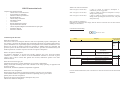
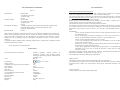
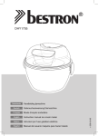
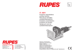
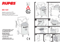
®
3
KX 135
5
2
!
14
11
6
7
1
4
Aspiratore pneumatico ATEX
ATEX Pneumatic suction cleaner
Aspirateur Pneumatique ATEX
ATEX Mobilier pneumatischer absauger
10
8
12
13
-ISTRUZIONI PER L’USO
E LA MANUTENZIONE
-OPERATING AND
MAINTENANCE
INSTRUCTIONS
-NOTICE D’EMPLOI ET
D’ENTRETIEN
-BEDIENUNGS-UND
WARTUNGSANLEITUNG
1
2
3
4
5
6
7
KX135 instruction book
Contents of the instruction book
General notes on Atex Directives
EC declaration of conformity
Machine technical specifications
Recommendations
General safety instructions
Installation manual
User manual
Routine maintenance manual
Special maintenance manual
General exploded diagram with information on spare parts
Pneumatic diagram
Warrantee certificate
Which zones and which hazards?
Zone 0 for gas (or 20 for dust):
Zone 1 for gas (or 21 for dust):
Zone 2 for gas (or 22 for dust):
a place in which an explosive atmosphere is present
continuously or for long periods
a place in which an explosive atmosphere is likely to occur
during normal operating
a place in which an explosive atmosphere is likely to occur
during normal operating and if it does occur, will persist for a
short period only
How to check for compliance?
Equipment of components that comply with the directive must bear the CE mark and the special
marking described below:
Classification and marking
II 3 D c T 50°C
ATEX European directions
What does ATEX mean?
ATEX is the name of two European Directives that control potentially explosive atmospheres. The
first, 94/9/EC, prescribes the minimum safety and health requirements of equipment and protective
systems intended for use in potentially explosive atmospheres and is aimed at manufacturers. This
directive has the task of bringing together the legislation in Member States for equipment and
protective systems for these risk areas. The second, 99/92/EC, prescribes the minimum safety and
health requirements of workers exposed to the risks of explosive atmospheres.
What is an explosive atmosphere?
An explosive atmosphere is one that may become explosive due to the local and working
conditions. It is defined as a mixture of air and inflammable substances in the form of gases,
vapours, mist or dust in which, after ignition has occurred, combustion spreads to the entire
unburned mixture.
What does the directive apply to?
Equipment and protective systems intended for use in explosive atmospheres.
Safety, control and monitoring devices that contribute to the safety operating of equipment and
protective systems.
All electrical, mechanical, hydraulic and pneumatic equipment.
What are the user’s obligations?
With regard to the prevention of explosions and relative protection, users are obliged:
to take suitable technical or organizational measures depending on the type of control
globally assess the risks of explosion
divide up the areas in which explosive atmospheres may occur
indicate areas defined as dangerous
Group
Category
Type of explosive
atmosphere
G
Gas
Vapours
Mists
I Mining
M1
Functional in an explosive
atmosphere
M2
Equipment de-energizes in an
explosive atmosphere
D
Dust
Zone
II Surface industries
Zone
1
Very high level of protection
0
20
2
High level of protection
1
21
3
Normal level of protection
2
22
For more detailed information, refer to the directives 94/9/CE and 99/92/CE and all the harmonized
standards.
EC declaration of conformity
KX135
Manufacturer:
Production plant:
Description of machine:
Machine model:
RUPES SPA
Via Marconi 3A, 20083
Vermezzo (MI)
ITALY
NETCO SRL
Via Meucci 28, 20083
Gaggiano (MI)
ITALY
Portable pneumatic suction cleaner for potentially explosive dust
produced during sanding or equivalent operations, with
fitting for pneumatic tool
KX135
With reference to annex X of the directive 94/9/CE of the European Parliament and Council of 23
March 1994, RUPES SPA declares that the machine in question complies with the minimum
safety and health requirements for the manufacturing of equipment and protective systems
intended for use in potential explosive atmospheres (described in Annex II of the 94/9/CE
directive).
Compliance with the minimum safety and health requirements is guaranteed by compliance with the
following harmonized standards:
-
see EC declaration of conformity sheet
Technical data
General characteristics of machine
Code
Portable pneumatic suction cleaner for
potentially explosive dust produced during
sanding or equivalent operations, with fitting for
pneumatic tool
KX135
EX marking
Supply pressure
Compressed air supply connection diameter
Filter surface
Filter material
BIA value
Suction capacity
Air consumption of suction cleaner
Vacuum level
Dry dust capacity
Noise level
Dimensions
Weight
II 3 D c T 50°C
7 bar
3/8”
0.5m2
Antistatic polyester
M
98m3/h
1000 l/min
1900mmH2O
20 liters
78 dB
70 x 54 x 90 (H) cm
30kg
Recommendations
Safety and accident prevention instructions
The machine is a portable suction cleaner with a fitting for the connection of a pneumatic tool,
which uses compressed air at a pressure of 7 bar to vacuum sanding dust.
The suction cleaner must be connected to a compressed air supply with a pressure 7 bar using a tube
with an internal diameter of 10 mm. During use, the vacuum cleaner must always be connected to
the grounding system by means of the pliers supplied.
RUPES spa does not accept liability for any damage, direct or indirect, caused by the failure to
comply with the instructions provided in these manuals.
The machine must only be used by trained and qualified personnel.
The machine must be located in a dry and adequately ventilated area where air is changed at least
once an hour with 50% of the total fresh air without the aid of special ventilation systems. The
temperature of the work area must be between 10°C and 40°C with humidity between 50% and
90%.
WARNINGS
Do not vacuum sanding dust from surfaces treated with paints that have not completed
the catalization cycle
Do not vacuum aggressive liquids or substances (i.e. acids , bases, solvents, etc.)
Do not vacuum flammable or explosive liquids (i.e. petrol, thinners, etc.)
Do not vacuum potentially explosive gases or vapors
In the event of leakage of dust from the unit, immediately close the compressed air
supply of the vacuum cleaner
In the event of a fire or explosion, follow internal safety instructions and procedures (as
indicated in the ATEX 99/9/EC Directive)
Always place appropriate warnings signaling the presence of a potentially hazardous
atmosphere next to the area in which the machine is being used (as indicated by
Directive 99/9/EC)
The machine complies with the ATEX 94/9/EC Directive and harmonized standards listed in the
declaration of conformity as equipment in category II 3 D.
The machine bears the safety markings specified below.
On the dust bin
The machine contains dust deposits and potentially explosive atmospheres.
The operator must not place near or inside the machine, especially in the dust bin, possible sources
of ignition such as: flames, gas or hot surfaces, electric parts, electrostatic discharges, mechanical
sparks.
On the rear panel
Technical specifications and ATEX marking label
Installation manual
WARNING The machine must be installed and started for the first time by qualified personnel
authorized by RUPES Spa
Package handling instructions
The machine is supplied in a box with overall dimensions and weight of
70x54x90 (H) cm – 30kg
comprising:
wooden platform
corrugated cardboard covering
binding straps
The box must be handled and stored in an upright position. Do not place any objects on the package
that weigh more and/or have a different sized base than the box. Avoid knocking the package or
damaging it when it is being moved.
Instructions for unpacking and disposal of packaging
Before opening the box, carefully examine its appearance. If it is damaged, shows signs of having
been opened or the documentation in the envelope attached to the outside is not complete, do not
proceed but send the box back to the sender taking suitable measures. Failure to do so will render
the warranty void.
To unpack the machine:
cut the binding straps;
remove the corrugated cardboard covering
Take the machine off the wooden platform
Take the key to open the inspection door
Set aside the bag of accessories
Inspection of package contents
The package contains:
the vacuum suction unit equipped with connection pliers for equipotential circuit and pneumatic
sleeve; the accessories bag containing a dust bag and instruction manuals.
Installation of machine
Place the machine on a stable and level surface. Verify that it is possible to connect the metal
suction cleaner pliers to the grounding system of the working area.
Connect the suction cleaner to the pneumatic sleeve supplied (see figure 1) with the machine and
connect:
The quick coupling to the pneumatic sleeve on the front right side of the suction cleaner
The suction head to the pipe union of the suction cleaner
Disconnect the supply pipe from the vacuum head using the quick fitting, then remove the vacuum
head using the two metal hooks (see figure 2).
Place the dust bag inside the drum and firmly fix it to the sleeve (see figure 3).
Place the vacuum head in the correct position above the drum and fix it using the metal hooks
supplied.
Connect the supply pipe to the vacuum head (see figure 4).
Connection to the pneumatic supply
Please note: use filtered and dry air only.
Verify that the supply faucet of the suction cleaner is closed.
Connect the supply faucet to a pipe with an internal diameter of 10 mm (see figure 5).
Adjust the supply pressure at 7 bar.
Connect the pneumatic tool to the fitting on the sleeve and the suction pipe to the socket on the
pneumatic tool.
WARNING: for a correct operation, the suction cleaner requires an amount of air equivalent to
1000l/min, added to the amount of air required by the connected pneumatic tool. Verify that the
compressed air plant is able to supply the required amount to the machine.
Connection to the grounding system
CAUTION: ALWAYS connect the machine to the grounding system of the plant using the
metal pliers, specifically during the use of the suction cleaner, the emptying of the dust bag
and its replacement.
Connect the metal pliers to a part of the area that is connected to the grounding system of the plant.
(see figure 6)
User manual
Parts of machine
1 – Suction pipe union
2 – Abrasive holder shelf
3 – Tool support
4 – Dust bin
5 – Vacuum head
6 – Ignition valve
7 – Grounding pliers
8- Suction cleaner frame
9 – hose supports
10 – compressed air supply
11- pneumatic tool plug
12 – fixed wheels
13 – castor wheels
14- technical specification and ATEX marking label
Operation
The supply of the pneumatic tool and suction cleaner can be controlled by means of the faucet
situated on the rear of the suction cleaner.
To protect operators, the pneumatic tool should always be started together with the suction cleaner
to avoid the dust produced from forming potentially explosive atmospheres.
Verify that the suction sleeve is correctly connected to the pneumatic tool and suction pipe union.
Always check the conditions of the dust suction sleeve before using the machine.
Turn the faucet to start the vacuum cleaner.
Switch the pneumatic tool on to start working.
At the end of the work, stop the tool, close the faucet to stop the vacuum cleaner and place the tool
on the support provided.
Use the side supports to wind the supply pipe and the suction sleeve at the end of the work.
Place the abrasives, work tools, etc. on the rear shelf.
Place the abrasives, work tools, etc. on the rear shelf.
Before moving the suction cleaner within the working area, make sure that the front breaks are
disconnected and that the metal pliers are not connected to fixed parts of the working area.
N.B.: the machine generally outputs air at low speed during operation.
Removing dust residuals
At the end of each working day remove the dust accumulated on the flat surface of the suction
cleaner (rear top, head, etc.). If dust residuals are present, make sure that the metal pliers of the
suction cleaner are connected to the grounding system of the plant and carefully remove the
residuals to avoid creating potentially explosive atmospheres.
Special maintenance manual
Potential problems
If dust is ejected from the suction cleaner, immediately close the supply faucet. Verify that the
faucet, head and filter are correctly fitted and the connections are firm. If leaks occur on the
compressed air pipes, close the supply faucet.
In the event of doubt or if you are unable to identify the leak, contact an authorized RUPES
representative.
Routine maintenance manual
Emptying the dust bin
WARNING: this operation may lead to the formation of potentially explosive atmospheres
and deposits. Avoid using potential sources of ignition next to the machine, for example:
mechanical sparks, electric parts, hot surfaces, flames, hot gases and electrostatic charges. In
the event of explosive atmospheres, always follow internal safety instruction and procedures
as indicated by the Atex 99/9/EC Directive.
Verify that the dust bag inside the drum has been filled at the end of each working day.
The dust bag has a maximum capacity of 7kg and a volume of 20 l, which should never be
exceeded.
If the removed bag is damaged, use utmost care following the internal safety instructions and
procedures applicable to explosive atmospheres indicated in the Atex 99/9/EC Directive.
NEVER reuse the dust bag and use ONLY RUPES bins code 001.1606/5.
Store the spare bags in a dry area.
Bags should be disposed in accordance with law requirements and internal safety regulations
applicable to the handling of potentially explosive dusts.
Always verify that the metal pliers are connected to the grounding system of the plant before
performing this operation.
Close the compressed air supply faucet on the rear of the suction cleaner.
Disconnect the supply quick fitting from the suction cleaner before removing the latter.
Remove the locking metal hooks and carefully lift the suction cleaner head with the handle
provided.
Rest the head on the worktop.
Loosen the flange of the dust bag from the suction pipe union, then close the dust bag with the cap
to prevent dust from leaking during transport.
Carefully lift the dust bag and place it in a dedicated area within the plant.
Remove dust residuals from inside the bin.
Place a new dust bag inside the bin and connect the flange to the suction union pipe.
Verify that there are no signs of damage or lacerations on the filtering fabric.
Place the head on the dust bin verifying that it is correctly oriented.
Fix the head with the two metal hooks.
Connect the compressed air supply to the head of the suction cleaner using the quick fittings.
WARNING: Special maintenance must be performed by qualified personnel authorized by
RUPES Spa.
In the event of defects or breakages, contact the dealer for replacement by
qualified personnel or personnel authorized by RUPES SPA.
Before accessing the pre-filter, stop the suction unit.
RUPES shall not be held responsible for damage or malfunctioning caused by repair work,
replacement and uninstallation performed by unauthorized persons. You are advised to refer to
internal regulations or requirements for safe conduct in the presence of potentially explosive
atmospheres or dust deposits.
Special maintenance regards:
Filtering element: replace it if damaged or clogged following the procedure outlined below.
Wear a 3M 06922 type dust mask.
Disconnect the supply from the suction cleaner on the head.
Release the head loosening the metal hooks.
Rest the head on the floor and loosen the locking nut.
Loosen the metal wing nut and release the filter grounding cable.
Remove the locking nut and carefully extract the filter.
Place the filter in a bag and dispose of it accordingly.
Place the new filter on the frame and fit the locking nut making sure that it has been
correctly tightened.
Fix the filter grounding cable to the head by tightening the wing nut.(see picture 7)
Assemble the head on the suction cleaner fixing it in place with the metal hooks, then
reassemble the compressed air supply.
Compressed air supply pipes of the suction cleaner: check their integrity and sealing every 6
months.
Replacement of the suction cleaner parts: wheels, bin, head, metal pliers, suction sleeve, etc.
(check their integrity every 6 months)
Replacement or reparation of frame damages (check every six months)
To avoid problems or failures, it is advisable to have the machine and the parts listed inspected
every 6 months to make sure they are not damaged.
S.p.A.
20080 VERMEZZO (Mi) - Italy
Via Marconi, 3/A - Tel. +39 02 94 69 41
I
DICHIARAZIONE DI CONFORMITA’
Anno di apposizione della marcatura
Dichiariamo sotto la nostra esclusiva responsabilità che
l'aspiratore pneumatico mobile per polveri
Potenzialmente Esplosive rappresentato, è conforme ai requisiti
Essenziali di Sicurezza delle
Direttive:
UNI EN 13463-1:2004
Attrezzatura non elettrica per
atmosfere potenzialmente esplosive Metodo di base e requisiti;
UNI EN 13463-5:2004
Apparecchi non elettrici ad essere
utilizzati in atmosfere potenzialmente esplosive - Parte 5:
Protezione mediante sicurezza costruttiva "c";
L'analisi dei rischi di esplosione è stata eseguita secondo la
normativa
UNI EN 1127-1:2001
Atmosfere esplosive - Prevenzione
dell'esplosione e protezione contro l'esplosione - Parte 1: Concetti
fondamentali e metodologia;
La conformità dell'apparecchio è attestata dall'applicazione della
marcatura CE (secondo allegato
X della direttiva 94/9/CE) e dalle indicazioni di marcatura di seguito
riportate (secondo Allegato II
paragrafo 1.0.5 della direttiva 94/9/CE).
GB
CONFORMITY DECLARATION,
Year of affixing to CE mark: 96
We declare on our responsibility that the represented
Portable pneumatic suction cleaner for potential
explosive dust from sanding or similar for industrial use
is in conformity with Essential Requirements of Safety of
the Following Directives:
UNI EN 13463-1:2004 Non-electrical equipment
intended for use in potentially explosive
Atmospheres.
UNI EN 13463-5:2004 Non-electrical equipment
intended for use in potentially explosive
Atmospheres. Part 5: Protection by constructional safety
"c".
Explosion's risk analysis has been done following
directive:
UNI EN 1127-1:2001 Explosive atmospheres. Explosion
prevention and protection. Part 1 : Basic concepts and
methodology.
The equipment conformity is certified by CE marking
(described in Annex X of 94/9/CE directive)
and by the following special marking (described in Annex
II, 1.0.5 paragraph of the 94/9/CE)
F
DÉCLARATION DE CONFORMITÉ
Anné de apposition de la marquéture:
Nous déclarons sous notre propre responsabilité que l'aspirateur
pneumatique pour poussières potentiellement explosibles
représenté, est conforme à les Requises Essentiels de Sécurité
des Directives :
l'explosion 1ère partie : concepts fondamentaux et méthodologie
La conformité de l'appareil est prouvée par l'application du
marquage CE (selon l'annexe X de la
directive 94/9/CE) et par les indications de marquage reportées ciaprès (selon l'annexe II
paragraphe 1.0.5 de la directive)
UNI EN 13463-1 :2004
Equipement non électrique pour les
atmosphères potentiellement explosible ;
UNI EN 13463-5 :2004
Equipement non électrique pour les
atmosphères potentiellement explosibles 5ème partie : protection
par la sécurité de construction "c";
L'analyse des risques d'explosion a été effectué selon la norme
UNI EN 1127-1 :2001
Atmosphères explosible – Prévention
D
KONFORMITATSERKLARUNG
Jahr der Beifügung der Kennzeichnung
Wir erklären unter unserer ausschließlichen Verantwortung, dass
der dargestellte Mobiler pneumatischer Absauger zum Absaugen
von explosionsgefährdetem Staub für Industrieanwendungen den
wesentlichen Sicherheitsauflagen der folgenden Richtlinien
entspricht:
UNI EN 13463-1:2004
Nicht elektrische Geräte für den
Einsatz in explosionsgefährdeten Bereichen Basismethode und
Voraussetzungen;
UNI EN 13463-5:2004
Nicht elektrische Geräte für den
Einsatz in explosionsgefährdeten Bereichen – Teil 5: Schutz durch
bauliche Sicherheitsmaßnahmen "c";
Die Analyse der Explosionsgefahr wurde gemäß der folgenden
Bestimmungen ausgeführt:
UNI EN 1127-1:2001
Explosionsgefährdete Umgebungen –
Explosionsvorbeugung und Explosionsschutzmaßnahmen - Teil 1:
Grundlegende Begriffe und Methodologie;
Die Konformität des Geräts wird durch das Anbringen der CEKennzeichnung bescheinigt (nach
Anlage X der Richtlinie 94/9/CE) und durch die im Anschluss
aufgeführten Angaben zur
Kennzeichnung (gemäß Anlage II Absatz 1.0.5 der Richtlinie
94/9/CE).
S.p.A
Vermezzo, 28 febbraio 2003
IL PRESIDENTE
G. Valentini