1
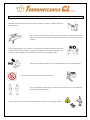
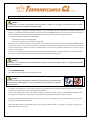
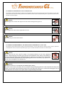
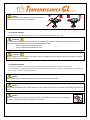
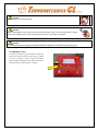
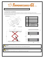
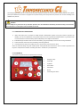
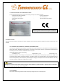
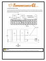
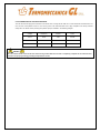
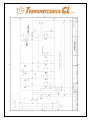
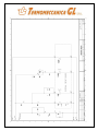
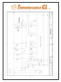
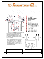
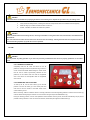
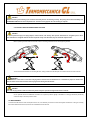
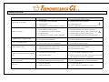
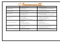
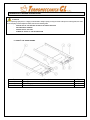
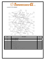
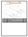
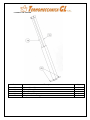
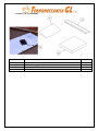
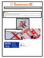
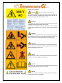
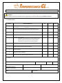
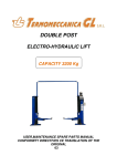
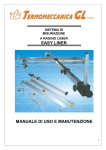
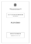
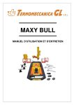
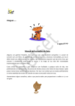
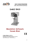
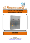
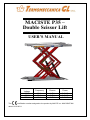
MACISTE P35 – Double Scissor Lift USER’S MANUAL Voltage 230 V 400 V 575 V The Frequency Phases Power 60 Hz 50 Hz 60 Hz 1 PH 3 PH 3 PH 3.0 kW 3.0 kW 3.0 kW certification number assigned to the product by ANCCP is n. MAC220AT496 dated 13-05-2011 Manufacturer Address: Type Model Termomeccanica GL Via Luciano Giangolini 42035 Felina, Castelnuovo ne’ Monti Reggio Emilia, Italia Double Scissor Vehicle Lift MACISTE P35 Manufacturing year TERMOMECCANICA GL Warranty & Liability This lift is warranted by TERMOMECCANICA GL to be of satisfactory quality, fit for its purpose and comply with applicable TERMOMECCANICA GL specifications for the period of twelve months from the date of installation (Verified by reference to your proof of purchase). This warranty dose not apply if the lift has: 1) been mishandled, misused, wilfully damaged, neglected, improperly tested, repaired, altered or defaced in anyway 2) a defect arising as a result of any failure to follow instructions either in the manual or product specification 3) a defect arising from the use of non-TERMOMECCANICA GL approved parts or ancillary items attached to or in connection with the lift. 4) a malfunctioning or damage arisen out of natural disaster such as earthquake, flood and so on. 5) Been installed by unauthorized personnel. Warranty does not affect your statutory rights as a consumer. Warranty conditions may vary depending on the country in which you bought the lift. DECLARATION OF CONFORMITY DECLARATION DE CONFORMITE KONFORMITATSERKLARUNG DICHIARAZIONE DI CONFORMITÁ Manufacturer, Fabricant, Hersteller, Costruttore TERMOMECCANICA GL Srl - Via Luciano Giangolini - 42035 Castelnuovo ne’ Monti - Reggio Emilia (Italia) Product type, Genre de produit, Produktart, Tipo di prodotto Double Scissor Lift Type, Model, Type, Modello Maciste P35 Serial Number, Numéro de Série, Seriennumer, Numero di Serie -Noi, la società dichiara di qui con la nostra responsabilità che il prodotto sopra citato è conforme al campione sottoposto a prova da parte dell'Organismo Notificato e soddisfa i requisiti delle seguenti direttive: Machine Directive, Directive Machines, Maschinen-Richtlinie, Direttiva Macchine 2006/42/CE Low Voltage Directive, Directive Basse tension, Niederspannungsrichtlinie, Direttiva Bassa Tensione 2006/95/CE Electromagnetic Compatibility Directive, Directive compatibilité electro magnétique, EMV Richtlinie, Direttiva Compatibilità Elettromagnetica 2004/108/CE La conformità è stata controllata con l'ausilio delle seguenti norme armonizzate/The conformità has been checked with the help from the following harmonized rules: EN ISO 12100-1 - - EN ISO 12100-2 EN 60204-1 EN 1493 EN ISO 13857 EN ISO 13850 EN ISO 11202 EN ISO 14121-1 Dichiarazione relativa alla Direttiva 97/23/CE: questo impianto è escluso dal campo di applicazione della direttiva sulle attrezzature a pressione secondo quanto indicato all'articolo 1, sezione 3.6. La sicurezza relativa all’utilizzo di fluidi in pressione di pressione con questa apparecchiatura è stata valutata secondo la pratica ingegneristica consolidata (Sound Engineering Practice, SEP) Declaration related to the Directive 97/23/CE: this equipment is not included in the application field of the directive on the pressure equipment as to the art. 1 section 3.6. The safety related to the use of pressure oil has been evaluated aclording to the sound engineering practice (SEP). Nome, indirizzo e numero di identificazione dell'organismo notificato/Name address and identification number of the certifying body. ANCCP Srl (Agenzia Nazionale Certificazione Componenti e Prodotti), Via Rombon, 11 – 20134 Milan – Italy – ID nr. 0302 EC-type Certificate, Attestation CE de type, EG-Baumusterprüfbescheinigung, Attestato CE di Tipo MAC220AT496 Dated, En date du, Datiert, Datato Guarded by, Classé a la, Abgelegt bei, Archiviato presso TERMOMECCANICA GL Srl - Via Luciano Giangolini - 42035 Castelnuovo ne’ Monti - Reggio Emilia (Italia) Person authorized to compile the technical file, personne autorisée à constituer le dossier technique, befugt ist die technischen Unterlagen zusammenzustellen, persona autorizzata a costituire il fascicolo tecnico Sig. Romeo Giangolini c/o TERMOMECCANICA GL Srl - Via Giangolini - 42035 Castelnuovo ne’ Monti - Reggio Emilia (Italia) Castelnuovo ne’ Monti (RE - Italy) Firma / Signature INDEX 1. FOREWORD 2. GENERAL SAFETY AND ACCIDENT PREVENTION RULES 3. WORKPLACE ENVIRONMENT 4. RESIDUAL HAZARDS 5. 4.1. Crushing Hazard 4.2. Hazard of the Vehicle to fall from the lift 4.3. Hazard of overturning of the vehicle do to instability of the load 4.4. Electric Hazard 4.5. Generic Hazards 4.6. Emergency Stop MACISTE P35 DOUBLE SCISSOR LIFT 5.1. Description of the machine 5.1.1. Features of the machines 5.1.2. Controls 5.1.3. Layout 5.1.4. Forecasted Use 5.1.5. Identification and CE Marking label 5.2. Installation 5.2.1. Packing type, shipping, handling, hoisting points 5.2.2. Storage 5.2.3. Unpacking 5.2.4. Foundations 5.2.5. Pit 5.3. Assembly 5.3.1. Authorised Personnel 5.3.2. Needed Tools 5.3.3. Position of the workstation 5.3.4. Connection of the electric box 5.3.5. Connection of the hydraulic circuit 5.3.6. Final Connections to the control circuits 5.4. Preliminary Operations 5.4.1. Hydraulic Circuit 5.4.2. General Preliminary Operations 5.5. Use 5.5.1. Loading of a vehicle 5.5.2. Operating the lift 5.5.3. Safety Precaution during the Use 5.6. Maintenance 5.6.1. Regular checks 5.6.2. Specific Checks 5.6.3. Recommended Hydraulic Oil 5.6.4. Cleaning 6. DISMANTLING OF THE MACHINE AND SCRAPPING 7. TECHNICAL ASSISTANCE 8. TROUBLE SHOOTING 9. SPARE PARTS: GENERAL INSTRUCTIONS 9.1. Spare Parts’ List: Base Frames 9.2. Spare Parts’ List: Scissors 9.3. Spare Parts’ List: Top Platforms 9.4. Spare Parts’ List: Pistons 9.5. Spare Parts’ List: Accessories 10. SAFETY PICTOGRAMS ON THE LIFT 11. CHECK LISTS 11.1. Initial Check 11.2. Periodical Checks CAUTION This document is the exclusive property of TERMOMECCANICA GL which forbids its reproduction, either in part or wholly, without its explicit approval in writing. WARNING The machine shall not be put in service until when the user has been completely read and understood the contents of this manual. 1 FOREWORD This manual contains the instructions for handling, installation, use and maintenance of the double scissor lift MACISTE P35 This manual is an essential part of the machine and it shall be opportunely taken care of. In case of its damaging or loss, a duplicate can be asked to the manufacturer who will provide a copy. The content of the present is in compliance with the Directive 2006/42/CE. WARNING Compliance with the instructions herein provided will allow for the safe operating of the system during the handling, installation, operating and maintenance stages and assure at the same time the proper functioning and cost-effectiveness of the machine. TERMOMECCANICA GL declines every responsibility for damages to things and/or persons consequences of a negligent use of the machine or to the lack of observance of the instructions contained in this manual. 2 GENERAL SAFETY AND ACCIDENT-PREVENTION RULES PAY CAREFUL ATTENTION TO THE DANGER SIGNS WHEN THEY APPEAR IN THIS MANUAL. THERE ARE THREE LEVELS OF DANGER SIGNS. DANGER This sign warns that, if the operations described are not carried out correctly, the user is exposed to serious risks which may result in injuries, death or long-term damage to his health. WARNING This sign warns that, if the operations described are not carried out correctly, the user is exposed to risks which may result in injuries, death or long-term damage to his health. CAUTION This sign warns that, if the operations described are not carried out correctly, the machine risks being damaged. WARNING Only authorised persons can operate the lift. Any person authorized to operate the lift shall be given copy of the manual; the owner of the lift shall make sure that any person authorized to use the machine has fully read and understood the present manual, therefore knowing how to use the machine in safe conditions. A safe use is guaranteed only meticulously following the instructions listed in this manual. DANGER In order to prevent risks to third parties and/or damages to things, before any operation takes place and before starting any working cycle, the user shall make sure that there are not things or persons close to the lift. DANGER Before using the lift, make sure that required protective apparels are used (protective gloves, goggles…). This manual is addressed to the user of the lift and to the person who has the responsibility of its correct and safe use. Read carefully the warnings contained in this manual, which is also supplying the indications for a correct and hazard free use of the machine. Familiarize with the controls and the operations required for the use of the lift in emergency conditions. Always keep this manual by the machine, in order to consult it in the event of any future possible need. The manual shall follow the machine in case it is sold. DANGER Immediately point out any problem or breakdown, including eventual defects detected on the control unit and/or on the hydraulic and electric connections, to the owner of the lift or to the person in charge of its safe use. The user in charge of the machine shall be a person fit for the job and shall have a perfect knowledge of how the system's equipment is to be used. He shall follow the instructions provided to guarantee their safety and the safety of others 3 WORKPLACE ENVIRONMENT Workplace environment must be clean and in orderly conditions. In particular, hazardous areas must be duly delimited. The work tools and materials shall not be left on the machines (or in places where these may interfere with its mechanical movements) or kept in places where they may fall and hence cause accidents. Any tool in deteriorated or in poor conditions is a potential source of hazards. Workplace environment must be clean and in orderly conditions. In particular, the hazard areas must be duly delimited. Any oil or grease on the floor shall be removed immediately to prevent any risk of slipping or falling. Each tool must be used exclusively for the use it was designed for and in the most suitable way. Do not clean nor touch any mechanical part while in motion.. The use of loose-fitting working cloths (e.g. scarves, button-down shirts, etc.) can be hazardous. Always wear close-fitting garments. Any oil or grease on the floor shall be removed immediately to prevent any risk of slipping or falling. 4 RESIDUAL HAZARDS DANGER It is mandatory to the owner of the machine and/or the person in charge of it, to supply to the final user all the necessary information and aids to the safeguard of its physical health. All the various stages - Designing, Construction, Selection of the sub-contractors and Final Inspection - involving the manufacturing processes of the MACISTE P35 Double Scissor lift were carried out by TERMOMECCANICA GL with the outmost care and attention to assure compliance of the product with the strictest safety standards through its high mechanical and engineering quality. It is, however, necessary to specify that, notwithstanding: the attentions taken in the designing phase; the care and control given to the manufacturing process; the lift object of this manual has, however, some risks that, for the specific type of job to execute, cannot be completely eliminated with the aid of security systems. Such risks are later on listed. It is absolutely necessary therefore that the operator is informed of such risks and that uses the machine with the maximum precaution. Familiarize with the controls and the operations described in this manual to use the machine in safe conditions. Always keep this manual together with the machine so as to make immediately possible any future consultation. The manual shall follow the machine in case of its sale. A safe use is only guaranteed for the functions listed in this manual. DANGER Never use the machine before having verified that all the emergency devices (limit switches, buzzer…) are opportunely mounted, connected and working. 4.1 CRUSHING HAZARD This hazard is present during the lowering operation of the lift. DANGER In order to prevent risks to third parties and/or damages to things, before any operation takes place and before operating the lift, the user shall make sure that there are no things or persons close to it. The platform is equipped with a control system that, during the lowering process, automatically stops the descent when the distance between the lift’s main platform and the ground reaches 220 millimetres. To resume the working cycle the user shall release the lowering push-button and press it again. The successive lowering process, until the platforms touch the ground, is accompanied by a sonorous alarms signalling the presence of a hazard of crushing. The hydraulic circuits is designed in such a way that, if one line is broken, the remaining line can hold the load. Platforms can then lower but no further raising movement is possible. Each master lifting cylinder is also equipped with a safety parachute valve that stops any movement in the event of a failure in the hydraulic circuit (e.g. if a hose is cut). 4.2 HAZARD OF THE VEHICLE TO FALL FROM THE LIFT This hazard is present while driving the vehicle on/of the platform and during both the raising and the lowering phases. The user shall make sure that the vehicle is correctly positioned on the platforms of the lift, as per the requirements given in § 5,5, and that all the actions are taken at a reduced speed. DANGER Do not support the vehicle with any kind of device while lifting/lowering the lift. DANGER Do not shake the vehicle while supported on the lift. DANGER Do not lift only one side of the vehicle. 4.3 HAZARD OF OVERTURNING OF THE VEHICLE DUE TO INSTABILITY OF THE LOAD This hazard is present during both the raising and the lowering phases. The user shall make sure that the vehicle correctly is positioned on the platforms of the lift, as per the requirements given in § 5,5, and that all the actions are taken at a reduced speed. DANGER Do not raise the lift if the vehicle’s weight is not properly balanced on the load supporting devices. Before beginning the working cycle verify the correct disposition of the vehicle on the platform of the lift by stopping the lifting process immediately after the vehicle has lost contact with the ground. Make sure that the vehicle is properly balanced on the supporting pads and abort immediately any operation on the lift if the load appears to be unbalanced. DANGER Do not overload the lift. The maximum gross liftable weight is 3500 kg Any other use of the lift is not allowed, was not considered during the designing phase and could compromise the safety of the machine. Do not tamper with the maximum pressure valve in the power pack. By doing so it could result in damaging the lift and could expose the user to serious risks, injuries, death or long-term damage to his health. DANGER Place the vehicle on the lift making sure that its heaviest wheel track is placed on the front side of the platform. 4.4 ELECTRIC HAZARD This hazard is present if the electric connections are not compliant to the applicable safety local norms. ATTENTION Do not connect the lift to the electric line before having verified that the line itself is completely compliant to the enforced norm. Also make sure that the electric line can supply the needed power and that: - there is a properly working grounding circuit - there is a properly working protection circuit ATTENTION Before plugging the lift to the main power supply or before any maintenance work, make sure that the main switch of the power supply is set to the OFF (0) position. 4.5 GENERIC HAZARDS Any other use or operation not in compliance with this manual could cause damages to the user and or to the machine. An un-forecasted and unexpected use alters the technical characteristics for which the machine has been designed and manufactured and could then compromise its correct and safe use. DANGER The lift was designed for indoor operation only. Do not install and/or use this lift outdoor. DANGER It is absolutely forbidden to raise persons with this lift. Do not climb onto the load or on the load carrying devices while they are raised. DANGER Before operating the lift, make sure that the vehicle to be lifted does not have any fluid leakages. If fluids are spilled on the floor immediately remove them. DANGER Do not wash the vehicle on the lift. DANGER Before operating the lift, visually check all the components of the lift and in particular the safety devices for possible defects. Do not operate the lift even if any defect is detected. DANGER It is not allowed to perform any type of aid and/or maintenance operation to the machine, during its normal use. 4.6 EMERGENCY STOP In the case an emergency stop is needed, to interrupt the work on the machine, operate the main switch by rotating it into the “0” position. In order to resume the working cycle previously interrupted, the user shall reset the main button by turning it clockwise into the “I” position. 5 MACISTE P35 DOUBLE SCISSOR LIFT 5.1 DESCRIPTION OF THE MACHINE The MACISTE P35 lift is a double scissor type lift designed for servicing, tyre changing or repairing light vehicles and trucks. The maximum liftable gross weight is 3500 kg. Any other use of the lift is not allowed, was not considered during the designing phase and could compromise the safety of the machine. ITEM DESCRIPTION 1 Left platform 2 Right platform 3 Master Cylinder 4 Slave Cylinder 5 Base Frame 6 Platform Extension DANGER It is not allowed to perform any type of aid and/or maintenance to the lift while being operated. DANGER The lift was designed for indoor operation only. Do not install and/or use this lift outdoor. The loading supporting devices are moved by hydraulic pistons designed to operate with a max pressure of 30 MPa (300 bar). The hydraulic power pack installed on the machine is equipped with a pressure limiting valve that prevents the pressure of the oil from exceeding of the allowable max pressure. DANGER Do not modify for any reason the set-up of the max pressure valve. Its modification immediately voids the warranty on the machine and could have as a consequence serious hazards for the user. 5.1.1 FEATURES OF THE MACHINE 1) Italian made power pack is provided for reliable operation. Master/Slave hydraulic circuit gives maximum precision and reliability. The use of a master/slave circuit cylinders reduces as much as possible the residual hazards. To guarantee a safe use, the lift maintains a constant lowering speed not depending on the weight of raised vehicle. 2) Extendable Support Platform allows for maximum flexibility, giving the possibility to service short and long wheelbases. 3) Photocell sensors continuously check the leveling of the lifting platforms. 4) Convenient drive-on ramps are provided, both for in-ground and on-ground version of the lift. Smart and advanced design along with durable powder coating finished paint enhances the class of lift and its appearance for long time. Components are modular, minimizing down time in the event of a part replacement. 5.1.2 CONTROLS The Controls to operate the lift are all placed in the control box. 1 Emergency Stop 2 Power light 3 Up Button 4 Down Button 5 Main Switch 6 Buzzer 7 Photocell bypass switch 5.1.3 LAYOUT The lift has been designed for an exclusive use on the indoor. It has not been considered and thus it is not allowed its use on the outdoor. DANGER Make sure that all around the machine there is sufficient space in order to guarantee the correct use of the lift, according to the dimensions of the car to be repaired and in the respect of the local safety norms. DANGER Avoid working in conditions of insufficient light. 5.1.4 FORECASTED USE This device was designed for raising vehicles. It was not designed for any different use. In particular it is prohibited to use the lift to raise persons, using it as a scaff-holding, washing vehicles, exerting pressure. Any accessory or part installed on the lift or the vehicle shall be comprised in the compute of the raised weight. TERMOMECCANICA GL does not assume any responsibility for the eventual damages to persons, objects and/or to the lift, caused by an use which is inadequate and/or inconsistent with the prescription of this manual. DANGER Do not overload for any reason the lift. The maximum allowable lifting weight is agreed to be the maximum total weight that can be loaded on lift, thus it does not refer, e.g., just to the simple empty mass of the vehicle. DANGER Only use original accessories approved by TERMOMECCANICA GL for the specific use with the MACISTE P35 lift. 5.1.5 IDENTIFICATION AND CE MARKING LABEL On the metallic plate applied to the machine the following information are indelibly indicated: - Business name of the manufacturer - Country of Manufacture - Designation of the machine - Year of Construction - Serial number of the machine - Type and model of the machine - CE Logo The data indicated on the nameplate shall be always called back for any need of assistance and request of spare parts. 5.2 INSTALLATION Here we list the criteria and the prescription for a proper installation of the lift and the preliminary operation to perform a safe first use of the machine. 5.2.1 PACKING TYPE, SHIPPING, HANDLING, HOISTING POINTS The machine is supplied conveniently packed. Check that all the content corresponds to what agreed when ordering and that the packing has not been damaged during the transport. In the event an anomaly was found, do not proceed with the assembly and immediately contact the authorized TERMOMECCANICA GL dealer. The standard package content is the following: - Left Platform (1 unit) - Right Platform (1 unit) - Control Panel (1 unit) Pay particular attention to the handling of the packed lift and use a lifting device whose capacity is greater to the weight to be moved and/or raised (above 500 kg lifting capacity). The platforms should only be handled with a hoist & appropriate sling and must be accompanied by a second person to prevent dangerous swinging. The equipment chosen must be suitable for safe lifting & moving, taking into consideration the dimensions & weight. DANGER Always load, unload and handle the lift package paying the utmost attention to possible hazards, in particular make sure that there are no persons or things in the range of the lifting device. 5.2.2 STORAGE If the machine, before being unpacked, needs a temporary storage, keep it in a covered dry place. 5.2.3 UNPACKING Once positioned the load close to the point in which the machine shall be installed, remove the eventual packing. DANGER Execute any maintenance, installation and assembly operation on the lift wearing proper protective devices (gloves, shoes…). ATTENTION All the packing material shall be properly scrapped in respect of the enforced norms in matter of scrapping of refusals. 5.2.4 FOUNDATIONS DANGER Before proceeding with the assembly and installation of the machine, verify that the floor is of a suitable type to stand the load consequence of the use of the lift. Only install the lift on a horizontal floor, free from obstacles The floor where the machine is to be installed shall be constituted from un-fissured concrete, levelled, at least 16 cm of thickness, built with a resistance class of C25/30 minimum, allowing the fixing to the ground of the lift with the aid of the M10 anchors supplied with the machine. If these conditions are not satisfied, proper foundations will have to be prepared with a gravel floor with a minimum thickness of at least 50 millimetre; on the gravel floor the user shall lay a steel electro-welded mesh with quadrant of 10 cm and with a wire diameter equal or greater to 8 millimetre. On top of the mesh a concrete layer with a thickness of at least 160 millimetre shall be placed. 5.2.5 INGROUND INSTALLATION If you wish to install the lift inground, the pits shall be constituted from un-fissured concrete, levelled, at least 16 cm of thickness, built with a resistance class of C25/30 minimum, allowing the fixing to the ground of the lift with the aid of the M10 anchors supplied with the machine. Make sure that both pits have a constant depth of 105 mm and that they are levelled. The dimensions of the pits are shown in the following sketch: DANGER Verify that all around the machine there is sufficient space in order to guarantee the correct and safe use of the machine. 5.3 ASSEMBLY In order to guarantee an easy and correct installation and a safe use of the machine of the machine, the lift is delivered pre-assembled. There are however some detached parts that need to be assembled in the final location. 5.3.1 AUTHORISED PERSONNEL Only a person qualified, competent and acquainted to all the enforced norms in safety matter shall be allowed to install and/or use the lift. DANGER In order to properly install TERMOMECCANICA GL MACISTE P35 lift, read carefully this Manual first and refer only to somebody qualified by TERMOMECCANICA GL for the job. 5.3.2 NEEDED TOOLS Beyond the common workshop equipment, the following tools will be necessary: 1. A drill with Ø15 – L=80 mm (minimum) widia tap and dynamometric wrench 2. A lifting device, such as a Crane or Fork lift, with a minimum admissible load of 500 kg 3. Hydraulic Oil with a viscosity of 46 Cst at 40°C according to ISO 3448-ISO VG46 norms 5.3.3 POSITION OF THE WORKSTATION Only install the lift if the minimum height of the ceiling in the place of installation is 5000 mm. The minimum distance from the walls and from other machines must be 1000 mm. The minimum walking area must be 500 mm. If the lift is installed in a pit, make sure it is centred inside it, keeping as constant as possible (20mm) the distances between the lift itself and the pit’s walls. Position & align platforms into position and raise lift using a wood block to ensure it cannot drop. Drill holes (15mm Diameter x 80mm Depth) & remove any dust & debris before inserting bolts. It is permissible to use “packing” washers if necessary - Max. 10 mm. Fix platform into position using bolts supplied & tighten to specified torque. Align 2 nd platform st with 1 and then repeat previous steps. Fix the lift to the ground using the bolts supplied with the machine DANGER Only use the fixing bolts supplied with the lift to fix the lift to the ground. Lock the bolts with the dynamometric wrench, verifying that the tightening torque is equal to 30 N·m. DANGER Verify that all the bolts are properly tightened before proceeding with the installation of the machine. It is prohibited to use or even test the lift if only one of the dowels has not been correctly positioned or if the tightening torque of all of them has not been verified. 5.3.4 CONNECTION OF THE ELECTRIC BOX The user will have to supply the connection to the electric line. To doing that he shall use a 4 wires cable with minimal section of 2 mm² for each of the phases and of 2.5 mm² for the ground. The cable shall also have a plug compliant to the locally enforced safety laws. The electric motor powering the hydraulic pump is available in the following voltages: Voltage Frequency Phases Power 575 V 50 Hz 3 PH 3.0 kW 400 V 50 Hz 3 PH 3.0 kW 230 V 60 Hz 1 PH 3.0 kW DANGER Do not connect the lift to the electric line before having verified that the line itself is completely compliant to the enforced norm, that there are properly working grounding and protection circuits. 5.3.5- CONNECTION OF THE HYDRAULIC CIRCUIT Inside each master cylinder and each support cylinder there is a parachute valve installed; its function is to block instantaneously the descent of the carriage if a hose is accidentally cut. Before using the lift, it is necessary to fill up the tank of oil, verify the correct assembly of the hoses connecting the hydraulic power unit to the master cylinder and the master cylinder to the slave. Connect the hydraulic pipes between the platforms, taking care to ensure the elbow connections are positioned to prevent damage when fitting the Cover Plate. Before using the lift, it is necessary to fill the oil tank, connect the hydraulic hoses connecting the power pack to the master cylinder and the hoses connecting the master/slave synchronisation circuits, and bleed the air out of the circuits. When you connect the hoses, make sure to connect the hoses matching the colours on the label on their fittings and that the elbow fittings are positioned in such a way that they are not damaged during the normal use of the machine. Connect the hoses as show on the sketch on the right. Description Description A SAE 100 R1 AT 1/4 FG 1/4 - FG 1/4 L. 4900 C SAE 100 R1 AT 1/4 MF 1/4 - FG 1/4 L. 1650 B SAE 100 R1 AT 1/4 FG 1/4 - FG 1/4 L. 4200 D SAE 100 R1 AT 1/4 MF 1/4 - FG 1/4 L. 1650 5.3.6- FINAL CONNECTIONS TO THE CONTROL CIRCUITS - Make electrical connections to the Solenoid switches, ensuring that all pins are securely in position inside the connector block. - Dress both the hydraulic pipe & ducting with plastic cable ties, ensuring they are positioned centrally between the cables to prevent any possibility of chaffing - Connect hydraulic pipes to Power Pack, ensuring all hydraulic connections are secure. - Run cable from Control Box to Power Pack, make Connections to motor connector block terminals (U1, V1, W1) and refit cover plate. ATTENTION The internal wiring (star or delta) of the motor could change without prior notice. The internal wiring of the electric motor (and as such the motor connector plates) should not be changed by the user for any reason. - Install limit switches and synchronisation photocell in position. DANGER Please note that the Limit Switch is a safety device and the lift must not be operated unless fitted correctly. 5.4 PRELIMINARY OPERATIONS ATTENTION There could be the presence of air in the hydraulic circuit, especially after the first installation or following some maintenance jobs. Before using the lift, it is mandatory to fulfil the following operations: 5.4.1 HYDRAULIC CIRCUIT 1. Fill the tank with hydraulic oil up to the level shown on the tank itself. ATTENTION Only use the type of Oil authorized by TERMOMECCANICA GL (see §5.6.3). 2. Switch on the control box by rotating the main switch into the I position. 3. Energise the hydraulic pump pushing the UP button on the control box. During installation it could be necessary to temporary disable the photocell. The control box is equipped with a manual by.-pass switch that overrides the photocell control. DANGER Only a trained person should be allowed to perform the lift installation. The photocell by-pass should be used exclusively during the installation of the lift. Always remove and keep in a safe place the key controlling the by-pass switch before using the lift to lift vehicles. 4. 5. Run both platforms UP/DOWN for several cycles to eliminate the air. Raise both the main platforms to top position. When the top position is reached, keep pushing the UP buttons. The automatic by-passes (#11 and #12 in the scheme of page 20) will feed oil to the master/slave connection circuits. ATTENTION Under particular installation conditions (low ambient temperature, long hoses between lift and control box..), there could be a small a-synchronisation in time when the movement of the two platforms is started. This should not be considered a defect, does not compromise the safe use of the lift and should not be confused with an a-synchronisation consequence of a bad installation. 6. ONLY WHEN OPTIONAL ADJUSTING VALVES ARE INSTALLED: Are available, as optional, regulating valves that enable to fine tune the oil flow going to each platform. If the lift is synchronised but one platform moves slightly before than the other, then the oil flow going to this platform should be reduce by slightly closing the appropriate valve. In order to do that, rotate clockwise the knob of the valve until a satisfactory setup is reached. ATTENTION The lowering speed of the lift is set in the factory and does not depend on the weight supported on the lift. Eventually particular rigid ambient temperatures – below 10°C – could result in slower lowering/lifting speeds. This is not to be considered a defect of the lift; the extent of the effects of a low ambient temperature could be reduced by using a lower viscosity oil. Check §5.6.3 of this manual and contact TERMOMECCANICA GL technical assistance to get information on the most suitable type of oil to be used. DANGER The parachute valve is setup and tested at the factory to operate in standard working conditions (20°C and 46 Cst oil) with a load on the platform comprised between 40% and 100% of the nominal maxim load (between 1400 kg and 3500 kg). The setup of the valve can be heavily affected by the working conditions (including temperature, oil viscosity, humidity and minimum load on the platform). If the lift is to be used in different working conditions from the standard design criteria, then the parachute valve setup shall be verified and approved by authorised personnel before any working operation takes place. A wrongly setup parachute valve could generate a serious hazard because in the event of a hydraulic failure would not properly work and stop the fall of the lift. 5.4.2 GENERAL PRELIMINARY OPERATIONS Before starting each working cycle, the user shall perform the following checks: 1. Check that all the bolts/screw - and in general all the components that during the use could have gone loose are tight. 2. Verify that the lift is properly fixed to the ground. 3. Verify all the hydraulic and electric connections. DANGER Check that all the screws/bolts are properly tight after the first 4 working hours. Repeat this procedure every 50 working hours. 4. Verify that all the safety devices, including limit switches and photocell sensors are installed and work properly. 5. Make the lift go up and down several time with no load on it. 6. Grease, if needed, the sliders rails inside each platform. DANGER Clean the machine after each working session, removing all the debris on the ground that could, with the time, cause malfunctions and hazards. The user shall have the same care that has for the lift also for the surroundings. If during the work there were liquids lost from the car that was being repaired, dry up the lift as soon as possible. 5.5 USE DANGER Do not perform any lifting operation if you have not previously controlled that the vehicle is properly positioned on the rubber pads. 5.5.1 LOADING OF VEHICLES Completely lower the lift. Drive the vehicle on the lift platforms, verifying that all the requirements of §4.2 and 4.3 of this manual are fulfilled. Before lifting the vehicle check that the load is shared symmetrically between the two platforms; for this reason make sure that the longitudinal axis of the vehicle is correspondent with the longitudinal axis of the lift. 5.5.2 OPERATING THE PLATFORM To start-up the lift, turn the main switch (4) into the ON position. Push the UP button (2) in the control panel and raise the lift until the wheels of the lifted vehicle loose contact with the ground. Before continuing, make sure that the vehicle is correctly positioned on the load supporting platforms. Push then the UP button (2) until the desired working height is reached. To lower the lift to the ground push the DOWN button (3). During the lowering process, once the main platforms reaches 220mm from the ground, the lift will automatically stop to prevent possible crushing hazards. In order to resume the descent, release and push again the DOWN button (3) DANGER Before and during each working cycle check that the safety devices are working correctly. Stop using the lift and immediately call TERMOMECCANICA GL technical department for assistance if they appear not to be working as required. 5.5.3 SAFETY PRECAUTIONS DURING THE USE DANGER To prevent personal injury from flying objects, check all bolts, nuts and any other part for deformation or elongation prior to each use. Deformed or elongated materials must be replaced. If they look deformed, they are deformed. Replace them! Before operating the lifts make sure that the vehicle is correctly positioned on the load supporting devices. To limit the mechanical stress on the lifting devices, always position the heaviest part of the vehicle to the front side of the lift. DANGER Field of motion of the load on of the load carrying devices shall be free of obstructions. It is forbidden to people to stand in the field of motion of the load and of the load carrying devices during their movement. DANGER The load carrying devices shall be continuously observed by the operator throughout the motion of the lift. On the hydraulic block and additional connection for an optional pressure gauge is available. It is strongly advised to periodically check the setup of the max pressure valve. 5.6 MAINTENANCE To reduce the effects of the wear consequence of the use, it is necessary to execute a correct and regular maintenance. This type of activity, first of all extends the life of the lift, but also it is fundamental for its safe use. 5.6.1 REGULAR CHECKS DANGER Prior to any kind of maintenance and/or cleaning operation is performed, completely lower the platforms, unload the lift, make sure that there is no pressure in the hydraulic hoses and disconnect the power source from the machine. DANGER Modifications not authorized in writing by the technical staff of TERMOMECCANICA GL could affect the safe use of the lift. DANGER After any kind of maintenance and/or cleaning operation are performed, before re-starting the lift, make sure that all the protective devices are correctly mounted and that they have not been damaged. DANGER For the extraordinary maintenance of the MACISTE P35 lift, address exclusively to the qualified TERMOMECCANICA GL staff. 5.6.2 SPECIFIC CHECKS: WARNING Only use original TERMOMECCANICA GL spare parts. Only the original TERMOMECCANICA GL’s parts are approved for the specific use on the MACISTE P35 lift. The use of spare parts not approved by TERMOMECCANICA GL for the specific use with the MACISTE P35 lift not only result in termination of the warranty, but could also compromise the safety characteristics of the machine. PART MAINTENANCE CHART TIME GAP TYPE OF CONTROL AND/OR MAINTENANCE Expansion Bolts 60 days Check if tight Hydraulic Connection 60 days Check if tight Oil Pump Filter 120 Days Clean with compressed air; replace every 250 days. Oil Pump 120 Days Check play and efficiency; authorised personnel. Cylinder gaskets 120 Days Check for oil leaks and eventually replace. Air/Oil Hoses 15 Days Check for damages and replace if needed. Plastic Pads 60 days Check for excessive wear end replace if needed. Grease the sliding rails. Oil Level 15 Days Check Oil Level and add if needed. Use only the suggested types of oil. maintenance only by 5.6.3 RECOMMENDED HYDRAULIC OIL Here equivalents hydraulic oils recommend by MANUFACTURER DESCRIPTION TERMOMECCANICA GL for the use with the MACISTE P35 Aral Vitam GF 46 lift are listed: BP HLP 46 If any of the above mentioned oils are available, use an oil Esso Nuto 46 with a viscosity of 46 cst at 40°C according to the ISO 3448- Esso Hydraulioil 46 ISO VG 46 norm. Fina hydran 46 Klockner Rando oil HDA 46 Raab karcher Aval Vitamin GF 46 ATTENTION Eventually particular rigid ambient temperatures – below 10°C – could result in slower lowering/lifting speeds. This is not to be considered a defect of the lift; the extent of the effects of a low ambient temperature could be reduced by using a lower viscosity oil. Contact TERMOMECCANICA GL technical assistance to get information on the most suitable type of oil to be used. DANGER The complete change of all the hydraulic oil and the cleaning of the tank are strongly advised every 5 years or after every 500 days of use. The exhausted oil will have to be scraped according to the locally enforced laws. 5.6.4 CLEANING For the proper conservation of the system, provide for the regular cleaning of the machine by removing all the dust and/or parts of cloth lost while working. When cleaning, use non-corrosive and non-pollutant detergents that do not react with the paints used on the machine. Use compressed air to clean the power unit. DANGER Clean up the lift after every working session, removing all the impurities that could, with the time, being cause of malfunctions and dangers. If during the work there were liquids lost from the car that was being repaired, dry up the lift as soon as possible. 6 DISMANTLING OF THE MACHINE AND SCRAPPING The system must be put out of service and disassembled only when its replacement has been decided. Regardless of any considerations on the convenience of the reuse of the machine either in part or as a whole, it must be stressed that the scattering of potentially toxic components is extremely hazardous. The lift was built mainly with metals, plastic materials, electric power cables, oils and lubricants If the demolition is carried out by your personnel, the various components must be divided by sorting them by type. These are to be handed over to specialized and (authorized) firms for the disposal of the various materials: Aluminium-steel-copper Plastic-rubber DANGER Hand over the used hydraulic oil only to the authorised firms that operate in compliance with the locally enforced law. DANGER Hand over all the material to authorised companies that operate in compliance with the locally enforced law. 7 TECHNICAL ASSISTANCE The technical service office of the Company is always available to answer your questions and satisfy your requests Manufacturer Address: Via Luciano Giangolini 42035 Felina, Castelnuovo ne’ Monti Reggio Emilia, Italia Tel +39 (0522) 184 8411 Fax +39 (0522) 184 8445 Contact Email: [email protected] 8 TROUBLE SHOOTING SYMPTOMS CHECK POINT ACTION a) Damaged fuses a) Check the fuses and replace if needed. b) The main switch is on the OFF position b) Rotate the switch into the ON position c) There is no power c) Check the electric line d) A safety device is not working properly or is activated. d) Refer to TERMOMECCANICA GL Technical assistance a) The quantity of oil in the tank is insufficient a) Add hydraulic Oil b) The UP button is not working properly b) Check the push button and its electric connections c) The hydraulic lowering valve is jammed open c) Check and clean the hydraulic valve, if needed replace d) The Oil Filter is dirty d) Check and clean the oil filter, if needed replace e) A safety device is not working properly or is activated. e) Refer to TERMOMECCANICA GL Technical assistance a) The max pressure valve is not properly set a) Refer to TERMOMECCANICA GL Technical assistance. b) The pump is not working properly b) Check and clean the pump, if needed replace a) The hydraulic lowering valve is not working properly a) Refer to TERMOMECCANICA GL Technical assistance. b) There is an object under one of the platforms b) Raise the lift and remove the object a) The hydraulic lowering valve is leaking a) Refer to Technical assistance. b) There are leakages in the hydraulic circuit b) Check the hydraulic circuit for leakages c) Hydraulic lines are not connected correctly c) Check hydraulic connections The lift is not going down pushing the lowering a) The platforms are not synchronised button b) Parachute valve kicked in The control box is not working The lift is not going up The loading capacity is lower than rated The lift is not completely lowering The lift is lowering by itself a) Raise the lift to synchronise the platforms and make sure that there are no objects preventing the lift to lower. b) Raise and then try to lower again. If the problem is not solved check hydraulic connections for a possible leak. The lift is not moving gently, but is rather a) There is air in the hydraulic circuit a) Clean the hydraulic circuit (see § 5.4.1) “jumping” up and down b) The hydraulic lowering valve is not working properly b) Refer to TERMOMECCANICA GL Technical assistance. a) Lifting over weight limit a) Lift within rated capacity b) Shortage of hydraulic oil b) “Top Up” hydraulic oil and bleed air in hose line Motor noise SYMPTOMS Descending malfunction Contaminated hydraulic oil Hydraulic oil leakage Ascending malfunction Motor is not running, noise from motor Circuit breaker is clicking Motor is turning but lift is not raising CHECK POINT ACTION a) Parachute valve is jammed a) Try raising lift & lower again b) Electrical problem b) Refer to TERMOMECCANICA GL Technical assistance c) Hydraulic lines are not connected correctly c) Check hydraulic connections a) Moist and other substance a) Defect in hose a) Replace hose b) Leakage from connections b) Tighten the loose connection c) Bad cylinder packing c) Contact TERMOMECCANICA GL Technical assistance a) Oil leak & defective motor or pump a) Contact TERMOMECCANICA GL Technical assistance b) Erratic movement b) Release air out of hydraulic system c) Pressure relief valve on c) Check relief pressure of valve (30 MPa) d) Hydraulic lines are not connected correctly d) Check hydraulic connections a) Defective motor a) Replace motor b) Blown fuse b) Find cause and replace fuse c) Push button not contacting c) Replace push button d) Not enough amp supply to motor d) Supply enough amp (electrician only) a) Bad contact on solenoid wire a) Replace b) Low amp circuit breaker used b) Check capacity of circuit breaker and change c) Damaged wire c) Check damage area and replace a) Motor is turning wrong direction a) Change the phase of wire and re-operate b) Hydraulic hose incorrectly fitted b) Check hose connection from motor and other connection area a) Regular change of oil (once every year and however first oil change 2 months after initial operation 9 SPARE PARTS: GENERAL INSTRUCTIONS ATTENTION When requesting spare parts, it is highly recommended to always specify not only the name of the person ordering them, the name of the Company and the telephone number, but also the following data: - DESCRIPTION OF THE MACHINE ON WHICH THE ITEM IS MOUNTED - MACHINE SERIAL NUMBER - DESCRIPTION OF THE ITEM - NUMBER OF PIECES OF THE REQUIRED ITEM 9.1 PARTS’ LIST: BASE FRAMES Item 1 1a 2 Description Base P1 Base P2 M 6x10 EI Nut Q.ty 1 1 8 9.2 PARTS’ LIST: SCISSORS Item 3 4 5 6 7 8 9 10 11 12 13 Description Lower outside arm Lower inside arm Upper outside arm Upper inside arm Kit lever Kit slip plate lever roller Kit lower slide Kit upper slide Kit central joint pin front arm Kit coupling pin of rear arms Kit coupling pin of arms-base-platfom Q.ty 2 2 2 2 2 1 1 1 8 4 8 9.3 PARTS’ LIST: TOP PLATFORMS Item 14 15 16 17 Description Upper platform Platform extension P1 Platform extension P2 Kit extension pin Q.ty 2 1 1 1 9.4 PARTS’ LIST: PISTONS Item 18 18a 19 19a 20 Description Master Piston P1 Master Piston P2 Slave Piston P1 Slave Piston P2 Kit piston lower fixing pin Q.ty 1 1 1 1 2 9.5 PARTS’ LIST: ACCESSORIES Item 21 22 23 24 Description Space cover Short front ramp Hose cover L 700 Pads’ Kit Q.ty 2 2 4 4 10 SAFETY PICTOGRAMS ON THE LIFT The safety pictograms installed on the lift are shown in the pictures of this page. DANGER The user of the machine must be a person able to fully understand and recognise all the pictograms installed on it. The safety stickers shall not be taken away, damaged or destroyed. The owner of the machine and/or the person in charge of it shall immediately replace any damaged or partially unreadable pictogram. The following information are fixed on the lift: Lifting capacity DANGER Do not overload the lift. Electric supply information DANGER (picture on the side is just as a reference) Do not connect the lift to the electric line before having verified that the line itself is completely compliant to the enforced norm, that there are properly working grounding and protection circuits. WARNING The machine shall not be put in service until when the user has read and completely understood the contents of this manual. A digest of the operation instructions taking into account possible existing hazards are fixed on the control box of the lift and are readily visible. WARNING In order to prevent risks to third parties and/or damages to things, before any operation takes place, the user shall make sure that there are not things or persons close to the lift before starting any working cycle. WARNING In order to prevent pinching hazards, before any operation takes place, the user shall make sure that there are not things or persons close to the lift before starting any working cycle. DANGER Do not lift persons on the lift. This machine was designed to lift vehicles only, this is not a device designed to lift persons. WARNING The machine shall not be put in service until when the user has read and completely understood the contents of this manual. DANGER Place the vehicle on the lift making sure that its heaviest wheel track is placed on the front side of the platform. 11 CHECK LISTS DANGER DO NOT operate the lift until its installation has been approved by a Technician authorised by TERMOMECCANICA GL 11.1 INITIAL CHECK Check # 1 CHECK DESCRIPTION YES NO NOTES Check of the quality of the ground where the lift is to be installed. Concrete type___________ and thickness____________ 2 Check of the minimum safety distances from walls, other machines… 3 Check of the electric supply for compliance to applicable safety norms. 4 Check the levelling of the platforms. Functional check of the lift. 5 - UP/DOWN cycles to eliminate air from the hydraulic circuit. - Maximum pressure valve set-ups are correct (30 MPa). - Successful test of safety devices, including photocell. 6 Functional check of the lift, full load. 7 Check that the lift is securely fixed to the ground. 8 Check the oil level. 9 Check for eventual oil leakages. 10 Use instructions were delivered together with the lift. NOTES INSTALLATION SITE ADDRESS: CUSTOMER TERMOMECCANICA GL APPROVED TECHNICIAN DATE RESULT OF THE CHECK STAMP SIGNATURE STAMP SIGNATURE NEXT CHECK ACCEPTED REJECTED 11.2 PERIODICAL CHECKS Check # CHECK DESCRIPTION YES 1 Check cleanliness of the lift 2 Check oil level 3 Grease Sliding Pad rails 4 Grease Moving parts (pins and bushes) 5 Check hoses on hydraulic connections 6 Check for eventual oil leakages 7 Check the levelling of the platforms, possible wear on rollers/sliders 8 Functional check of the lift, loaded NO NOTES NOTES RESULT OF THE CHECK CUSTOMER TERMOMECCANICA GL APPROVED TECHNICIAN DATA ACCEPTED STAMP SIGNATURE STAMP SIGNATURE NEXT CHECK REJECTED Check # CHECK DESCRIPTION YES 1 Check cleanliness of the lift 2 Check oil level 3 Grease Sliding Pad rails 4 Grease Moving parts (pins and bushes) 5 Check hoses on hydraulic connections 6 Check for eventual oil leakages 7 Check the levelling of the platforms, possible wear on rollers/sliders 8 Functional check of the lift, loaded NO NOTES NOTES RESULT OF THE CHECK CUSTOMER TERMOMECCANICA GL APPROVED TECHNICIAN DATA ACCEPTED STAMP SIGNATURE STAMP SIGNATURE NEXT CHECK REJECTED