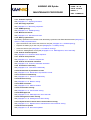
1
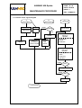
DATE : 09/06/06
INDEX : J
REF. : DGM96275
KANNAD
Z.I. des Cinq Chemins BP23
56520 GUIDEL - FRANCE
Telephone: +33 (0)2 97 02 49 49 Fax: +33 (0)2 97 65 00 20
Web : http://www.kannad.com - E-mail : [email protected]
KANNAD 406 Epirbs
MAINTENANCE PROCEDURE
Users are kindly requested to notify KANNAD for any
discrepancy, omission or error found in this manual.
Please report to our customer support:
E-mail: [email protected]
Tel.: +33 (0)2 97 02 49 00
KANNAD 406 EPIRBs
PAGE : 1 / LOR
DATE : 09/06/06
MAINTENANCE PROCEDURE
Ind.
Date
REF. : DGM96275
Description of modifications
G
06/10/03
Technical manual new version
H
20/07/04
Change of parts reference in compliance with new "Enterprise Resource Planning"
J
09/06/06
Beacon serial number references: pages 12 - 19 - 25 - 29
Bi-Phase modulation value: page 18
Modification of corrective actions on I144 PCB: pages 42 - 43
Action on "Reset" fault: pages 43 - 53
Add of task PC4 on I264 PCB: page 45
Add of I144 PCB layout: page 58
Copyright © KANNAD All rights reserved.
INDEX : J
KANNAD 406 EPIRBs
PAGE : 2 / LOR
DATE : 09/06/06
Copyright © KANNAD All rights reserved.
MAINTENANCE PROCEDURE
PAGE INTENTIONALLY LEFT BLANK
INDEX : J
REF. : DGM96275
PAGE : 1 / TDM
KANNAD 406 EPIRBs
DATE : 09/06/06
INDEX : J
MAINTENANCE PROCEDURE
REF. : DGM96275
CONTENTS
Copyright © KANNAD. All rights reserved.
Page
1 . KANNAD 406 EPIRBS PRESENTATION ....................................................................................... 1
1.1.Type and version ........................................................................................................................ 1
1.2.Commands and controls ............................................................................................................. 2
1.3.Programming .............................................................................................................................. 3
1.4.EPIRB mechanical assembly ...................................................................................................... 4
1.4.1.Old generation ( I144 and I144 with I246 or I191) .............................................................. 4
1.4.2.New generation (IMO / I264) ............................................................................................... 6
2 . KANNAS 406 PH / WH CONTAINER ............................................................................................. 8
2.1.KANNAD 406 PH / WH Container ............................................................................................... 8
2.2.KANNAD 406 SW Container ....................................................................................................... 9
2.3.KANNAD 406 S Container .......................................................................................................... 9
2.4.Installation instructions .............................................................................................................. 10
3 . MATERIEL USED FOR PROGRAMMING AND CONTROL ........................................................ 11
3.1.Measurement equipment .......................................................................................................... 11
3.1.1.Measurement equipment without opening the beacon ..................................................... 11
3.1.2.Measurement equipment with beacon opening ................................................................ 11
3.2.Test mock up ............................................................................................................................ 11
3.3.Tools ......................................................................................................................................... 11
3.4.Consumable .............................................................................................................................. 11
3.5.Interconnections ........................................................................................................................ 12
3.6.KITS for S / SW / PH / WH ........................................................................................................ 12
3.6.1.Upgrade ............................................................................................................................ 12
3.6.2.Repair ............................................................................................................................... 12
3.7.Safety straps ............................................................................................................................. 13
3.7.1.I144 PC board ................................................................................................................... 13
3.7.2.I264 PC board ................................................................................................................... 14
3.8.Battery test mock-up ................................................................................................................. 15
4 . TEST BENCH ................................................................................................................................ 16
4.1.Test bench input ....................................................................................................................... 16
4.1.1.Test bench configuration ................................................................................................... 16
4.2.Test bench ................................................................................................................................ 16
4.2.1.Measurement equipment configuration ............................................................................. 16
4.2.2.Assembly schematic ......................................................................................................... 17
5 . PREVENTIVE MAINTENANCE ..................................................................................................... 18
5.1.Periodic check: logical diagram ................................................................................................. 20
5.1.1.Opening Container ............................................................................................................ 21
5.1.2.Receiving inspection ......................................................................................................... 21
5.1.3.EPIRB opening ................................................................................................................. 25
5.1.4.Mechanical checks ............................................................................................................ 26
5.1.5.Battery check .................................................................................................................... 27
5.1.6.Control of flash sequence ................................................................................................. 28
5.1.7.Control of frequencies ....................................................................................................... 29
5.1.8.Control of automatic activation .......................................................................................... 29
5.1.9.Test before reassembly .................................................................................................... 29
5.1.10.Reactivation of protection circuits .................................................................................. 29
5.1.11.Control of conductivity ..................................................................................................... 29
5.1.12.Beacon closing ................................................................................................................ 30
5.1.13.Water activation .............................................................................................................. 31
5.1.14.Control after closing ........................................................................................................ 32
5.1.15.Watertight test, use of the bath ....................................................................................... 32
5.1.16.Sealing beacon after closing ........................................................................................... 32
PAGE : 2 / TDM
KANNAD 406 EPIRBs
DATE : 09/06/06
INDEX : J
MAINTENANCE PROCEDURE
REF. : DGM96275
CONTENTS
Copyright © KANNAD. All rights reserved.
Page
5.1.17.Replacement of release device and container closing .................................................... 33
5.1.18.Document updates .......................................................................................................... 37
5.2.4 Check and batteries replacement .......................................................................................... 38
5.2.1.Container opening ............................................................................................................. 39
5.2.2.Receiving inspection ......................................................................................................... 39
5.2.3.EPIRB opening ................................................................................................................. 39
5.2.4.Mechanical checks ............................................................................................................ 39
5.2.5.Battery replacement .......................................................................................................... 39
5.2.6.Control of flash sequence ................................................................................................. 39
5.2.7.Control of frequencies ....................................................................................................... 39
5.2.8.Control of automatic activation .......................................................................................... 39
5.2.9.Test before reassembly .................................................................................................... 39
5.2.10.Reactivation of protection circuits ................................................................................... 39
5.2.11.Control of conductivity ..................................................................................................... 39
5.2.12.Beacon closing ................................................................................................................ 39
5.2.13.Water activation .............................................................................................................. 39
5.2.14.Control after closing ........................................................................................................ 39
5.2.15.Watertight test ................................................................................................................. 39
5.2.16.Sealing beacon after closing ........................................................................................... 39
5.2.17.Replacement of release device and container closing .................................................... 39
5.2.18.Document updates .......................................................................................................... 39
6 . MAINTENANCE PROCEDURE ..................................................................................................... 40
6.1.Re-coding .................................................................................................................................. 40
6.2.Repair ....................................................................................................................................... 41
6.2.1.3rd generation of EPIRBs ................................................................................................. 42
6.2.2.4th generation of EPIRBs ................................................................................................. 44
6.2.3.Overhaul of metallizing ..................................................................................................... 45
6.2.4.Use of conductive paint kit ................................................................................................ 46
7 . ANNEXES ...................................................................................................................................... 47
7.1.Annex 1: battery replacement kit ............................................................................................... 47
7.1.1.Kit presentation ................................................................................................................. 47
7.1.2.Battery pack ...................................................................................................................... 48
7.2.Annex 2: Battery replacement modification ............................................................................... 49
7.3.Annex 3: WSS procedure level 4 .............................................................................................. 50
7.3.1.Generalities ....................................................................................................................... 50
7.3.2.Necessary equipment ....................................................................................................... 50
7.3.3.Control of connector .......................................................................................................... 50
7.3.4.PC board protection .......................................................................................................... 51
7.3.5.Water switch sensor replacement ..................................................................................... 52
7.4.Annex 4: Reset modification ..................................................................................................... 53
7.5.Annex 5: Flash replacement ..................................................................................................... 54
7.5.1.Flash replacement on beacons 305600<SN<326999 ....................................................... 54
7.5.2.Flash replacement on beacons 305600<SN<326999 ....................................................... 55
7.6.Antenna (or Antenna O-ring) replacement ................................................................................ 56
7.6.1.Antenna disassembly ........................................................................................................ 56
7.6.2.Antenna assembly ............................................................................................................ 57
7.7.Annex 7: I144 PCB ................................................................................................................... 58
KANNAD 406 Epirbs
PAGE : 1 / 58
DATE : 09/06/06
MAINTENANCE PROCEDURE
INDEX : J
REF. : DGM96275
1. KANNAD 406 EPIRBS PRESENTATION
1.1. Type and version
This maintenance procedure concerns KANNAD 406 Epirbs.
There are 3 types:
•
•
The survival type:
•
KANNAD 406 S (manual activation),
•
KANNAD 406 WS (manual activation and water activation).
The float free type (automatic activation):
•
KANNAD 406 F/P: Container made of polyester with an internal membrane (CAL87).
•
KANNAD 406 FH/PH: Container fitted with a HAMMAR release system (CAL 89).
•
KANNAD 406 WH: Container fitted with a HAMMAR release system (CAL 89).
Various versions are on the market further to technical evolutions:
300 000
305 600
317 225
323 154
327 000
EU1
with boards
I101B and I 102A
EU2
with boards
I101B and I 102A
EU3
with boards
I101C and I 102B
EU4
with boards
I101D and I102B
EU5
with boards
I101D and I102D
MONO
with boards
I144A or B
MONO1
with boards
I144C
MONO2
with boards
I144D
ETS 1
with boards
144C and I191
ETSI
with boards
144D and I191
IEC2
with boards
144D and I246
IEC2
with boards
I144E and I246D
OMI2
with boards
I264A to D
> 12 years = obsolete
Transmitter 121.5 / 406 MHz
- Flash
- Test button
- Flash
- Test button
- Flash
- WSS*
- Test button
- Flash
- WSS*
* WSS: Water Switch Sensor
IMPORTANT: Epirbs > 12 years do not fulfil the current standard. They should be declared obsolete
and replaced by a KANNAD 406 Epirb of new generation.
KANNAD 406 Epirbs
PAGE : 2 / 58
DATE : 09/06/06
MAINTENANCE PROCEDURE
1.2. Commands and controls
Figure 1 406 WH, SW, S, commands & controls
INDEX : J
REF. : DGM96275
KANNAD 406 Epirbs
PAGE : 3 / 58
DATE : 09/06/06
MAINTENANCE PROCEDURE
INDEX : J
REF. : DGM96275
1.3. Programming
KANNAD 406 beacons are encoded with the PKR2 programming kit without opening the beacon. The code
is entered inside the beacon memory with an optical pen placed over the beacon test lamp.
The PKR2 works under DOS environment or Windows environment when used with the WinProg software.
Detailed use of programming kit is explained in DOC94075 "COSPAS-SARSAT beacon, KANNAD 406
EPIRB programming".
Figure 2 : Programming KANNAD 406 beacons
KANNAD 406 Epirbs
PAGE : 4 / 58
DATE : 09/06/06
MAINTENANCE PROCEDURE
1.4. EPIRB mechanical assembly
1.4.1. Old generation ( I144 and I144 with I246 or I191)
Figure 3: EPIRB 406, I144 version, mechanical assembly
INDEX : J
REF. : DGM96275
KANNAD 406 Epirbs
PAGE : 5 / 58
DATE : 09/06/06
MAINTENANCE PROCEDURE
INDEX : J
REF. : DGM96275
Table 1: I144 / I246, I144 / I191, Part List
I144
Part Number
Designation
Two-frequency antenna (SCA 3 SNC 121,5/406 MHz)
Blended cover + flash hole for MON
Blended cover + flash hole + BP hole
Conductive O-ring for cover
O-ring for flash / antenna
I 161 board (programming interface)
I 144 A/B/C/D/E board
ETSI I191 B board test button
WHI 246A BT / WSS board
Orange blended housing + ballast
Orange blended housing with WSS (IEC3)
Shielding plate
Ballast
Nylon washer for VMI06065 screw
TFHC 5X20 stainless steel screw
Stud bolt
Switch protective transparent cap
0131669
Unipol stable watertight switch
0125665
BP1 Test push button (for cover > 327000), for any replacement cover
0125742 / 0125743
BP1 Test push button (for cover < 327000).
0125747
Stainless steel bolt
Nylon thread Ø = 1mm
Ferrule (int. Ø = 2,2 mm, length 10 mm)
Stainless steel nut
Steel strut
Stainless steel grower washer
SAFT battery (SOCl2)
5101890
SARTECH battery (Limn O2) USA / CANADA
5101901
Flash (2 wires)
5101912
Float (Survival type)
5101941
Tether
0121015
Desiccant capsule
See“: Battery replacement kit 5101950” Fig 29 Cable clamp
Seal for switch (Epirb fitted with WSS)
WSS kit
5101947
WSS wire
0124192
5101903
5101945
0124024
0124059
5102780
Obsolete
Obsolete
Obsolete
5101911
5101916
Dangerous goods
N°
1
2A
2B
3
4
5
6
7A
7B
8A
8B
9
10
11
12
13
14
15
16A
16B
17
18
19
20
21
22
23A
23B
24
25
26
27
28
29
30
31
KANNAD 406 Epirbs
PAGE : 6 / 58
DATE : 09/06/06
MAINTENANCE PROCEDURE
1.4.2. New generation (IMO / I264)
Figure 4: EPIRB 406, IMO / I264 version, mechanical assembly
INDEX : J
REF. : DGM96275
KANNAD 406 Epirbs
PAGE : 7 / 58
DATE : 09/06/06
MAINTENANCE PROCEDURE
INDEX : J
REF. : DGM96275
Table 2: OMI version / I264 Part List
OMI version / I264
Part Number
Designation
Two-frequency antenna (SCA 3 SNC 121,5/406 MHz)
Blended cover + flash hole + BP hole
White O-ring for cover
O-ring for flash / antenna
I 275 board (programming interface)
I 1264 board
Orange non blended housing + ballast
Shielding plate
Stud bolt
Threaded circuit support
Nylon washer for VMI06065 screw
TFHC 5X20 stainless steel screw
Switch protective transparent cap
0131669
Unipol stable watertight switch
0125665
BP1 Test push button for cover > 327000).
0125742 / 0125743
Stainless steel bolt
Nylon thread Ø = 1mm
Ferrule (int. Ø = 2,2 mm, length 10 mm)
Stainless steel nut
Board screw
SAFT battery (SOCl2)
5101937
SARTECH battery (Limn O2) USA / CANADA
5101942
Flash kit (3 wires)
5101939
Float (S/WH)
5101941
Desiccant capsule
See“: Battery replacement kit 5101950” Fig 29 Cable clamp
Tether
0121015
Seal for switch
WSS kit
5101947
WSS wire
0124192
5101945
0124082
0124059
5101953
5101951
5101936
Dangerous goods
N°
1
2
3
4
5
6
7
8
9
10
11
12
13
14
15
16
17
18
19
20
21A
21B
22
23
24
25
26
27
28
29
KANNAD 406 Epirbs
PAGE : 8 / 58
DATE : 09/06/06
MAINTENANCE PROCEDURE
INDEX : J
REF. : DGM96275
2. KANNAS 406 PH / WH CONTAINER
Labelling (Fr, GB, Esp, ETC...) under customer requirements.
2.1. KANNAD 406 PH / WH Container
Beacon type CAL 89 automatic released with hydrostatic release system type H20
•
Container PH / WH (1): P/N 1200256
•
Hydrostatic release system (2): P/N 5103555
•
Manual locking system (5): P/N 5102004
Figure 5: Container Description
1B
1A
3
6
5
2
4
This container is used to protect an EPIRB (Emergency Position Indicating Radio Beacon) of KANNAD 406
type and to ensure that the beacon is released and operates automatically in the event of a ship wreck. It
should be installed on the wheelhouse and preferably in horizontal position, so that the beacon can rise
easily to the surface.
The CAL 89 (1A/B) makes an envelope that gives excellent protection to the beacon. This envelope is made
of IMPAX, a polycarbonate material extremely resistant to shocks, according to the double skin technique
filled with polyurethane foam. The release device used is the Hammar H20 hydrostatic release (2).
At a depth of 1.5 m to 4 m (4 to 12 ft.), the release system operates and cuts the locking axe (3). The cover
(1A) is released and allows the beacon (4) to rise to the surface: when the beacon leaves the lower part
(1B) of the container, it is automatically activated. Installation and operation instructions must be strictly
followed.
IMPORTANT: The HAMMAR release device must be replaced every two years from installation date.
It is possible to open the container manually by opening the manual locking system (5).
Weight of container: 2,95 Kg.
Size: 435 x 220 x 155 mm.
PAGE : 9 / 58
KANNAD 406 Epirbs
DATE : 09/06/06
INDEX : J
MAINTENANCE PROCEDURE
REF. : DGM96275
2.2. KANNAD 406 SW Container
•
SW container: 5101904.
•
Strap: 0131654.
•
Wedging foam: 5101902.
Figure 6 : Container for KANNAD 406 SW with water switch sensor
Lower
housing
Cover
2.3. KANNAD 406 S Container
•
S container: 5101891.
•
Strap: 0131654.
•
Wedging foam: 5101902.
Figure 7: Container for KANNAD 406 S without water switch sensor
Lower
housing
Cover
KANNAD 406 Epirbs
PAGE : 10 / 58
DATE : 09/06/06
MAINTENANCE PROCEDURE
INDEX : J
REF. : DGM96275
2.4. Installation instructions
The container should be installed on the wheelhouse and comply with the following instructions:
•
horizontal position;
•
clear area to allow the beacon to rise to the surface, should the ship sink. Watch rigging antennae or
shroud that could build obstacles (see figure hereunder);
•
easy access to the crew for manual operation;
•
fermly fixed to the deck with 4 screws as shown hererunder.
4 screws Ø 6
55
Do not obstruct these holes used for water draining
246
NOTE:
As each vessel is particular, one will have to adapt to each case and possibly make adjustment
parts.
PAGE : 11 / 58
KANNAD 406 Epirbs
DATE : 09/06/06
INDEX : J
MAINTENANCE PROCEDURE
REF. : DGM96275
3. MATERIEL USED FOR PROGRAMMING AND CONTROL
3.1. Measurement equipment
3.1.1. Measurement equipment without opening the beacon
Equipment
SERPE-IESM reference
PKR2 Programming Kit with software, optical pen and PC connection
1200361
IESM 406 tester MK II or equivalent
0139385
Faraday box
0137913
3.1.2. Measurement equipment with beacon opening
ATTENTION : handling should be performed on an antistatic plan, the measurement equipment
should be grounded. Do not wear synthetical clothes.
Equipment
SERPE-IESM reference
Oscilloscope (2 channels / 100 Mhz minimum)
Radio communication test bench (ROHDE & SCHWARZ or equivalent)
CMS50
Multimeter (Fluke 77 or equivalent)
Stabilised and adjustable power supply 4 Amper minimum, 0/20 Volts with
current and voltage gauges
3.2. Test mock up
Equipment
SERPE-IESM reference
J2 permanent 406 MHz Module for I144 (MON)
MTS 0506
Battery tester
MTS 0514
3.3. Tools
Designation
Supplier reference
Torque wrench (RADIAL) subvis antenna coaxial
R 282 318 000
Adjustable torque wrench from 10 to 120 cNm :
SAM ref 40
•
3 mm allen bit for beacon closing
•
13 mm socket for release system assembly
•
Flat bits for water switch sensor assembly
Iron solder with antistatic soldering bit 300°C
3.4. Consumable
Designation
Solder with incorporated flux (tin 60%, lead 40%)
SERPE-IESM reference
XMC00115
PAGE : 12 / 58
KANNAD 406 Epirbs
DATE : 09/06/06
INDEX : J
MAINTENANCE PROCEDURE
Designation
REF. : DGM96275
SERPE-IESM reference
Soldering with flux (60% tin, 40% lead)
0137610
Cleaning flux
0137612
Dust removal spray
0137644
Insulating and tropicalizing varnish
0137615
3.5. Interconnections
Designation
SERPE-IESM reference
2 coaxial cables
2 banana cables
1 BNC / SMC adapter R191 120
0126281
1 power cable (banana, female connector)
3.6. KITS for S / SW / PH / WH
3.6.1. Upgrade
Designation
SERPE-IESM reference
SAFT battery for beacons < 327000
5101890
SAFT battery for beacons > 326999
5101937
Battery replacement Kit
5101950
Conductive O-ring (black) for beacon cover < 327000
0124024
O-ring (white) for beacon cover ≥ 327000
0124082
Battery modification Kit for beacons fitted with I144 board
5101930
Water switch sensor Kit
5101947
Reset Kit
5101932
3.6.2. Repair
Designation
SERPE-IESM reference
Flash 2 wires for I144 board
5101912
Flash 3 wires for I264 board
5101939
Two-frequency antenna
0124192
PAGE : 13 / 58
KANNAD 406 Epirbs
DATE : 09/06/06
MAINTENANCE PROCEDURE
INDEX : J
REF. : DGM96275
3.7. Safety straps
IMPORTANT: To avoid destruction of the general fuse when testing 406 MHz beacons fitted with I144
and I264 PC boards, the safety under mentioned must be removed before any
intervention.
The purpose of this safety is to stop the beacon from transmitting in the event of a
microprocessor dysfunction causing 406 permanent transmission.
3.7.1. I144 PC board
Figure 8: I144 PCB, implementation
J1
Safety strap
ILS
A
Use MTS0506A to obtain 406 continuous transmission.
406 Test can be performed with connector J1 (A), interface for MTS0506.
Check the position of indexing slot.
KANNAD 406 Epirbs
PAGE : 14 / 58
DATE : 09/06/06
MAINTENANCE PROCEDURE
INDEX : J
REF. : DGM96275
3.7.2. I264 PC board
Figure 9: I264 PCB, safety strap
SAFETY 406
ST5
7
5
3
1
ST4
J3
8
6
4
2
Different selection modes:
•
1 - 2: 406 7 sec.
•
3 - 4: permanent 406 (7 sec. ON, 7 sec. OFF).
•
5-6: unmodulated 121.5 MHz.
ILS
PAGE : 15 / 58
KANNAD 406 Epirbs
DATE : 09/06/06
INDEX : J
MAINTENANCE PROCEDURE
REF. : DGM96275
3.8. Battery test mock-up
Figure 10: Battery test mock-up and assembly drawing
Voltmeter
-
+
V
Battery pack S/N 300 000 to 326 999
R = 10Ω
R
-
+
Battery pack from S/N 327 000
R = 5Ω
Battery
12,7
TESTER
MTS0514
Battery
Figure 11: Example of MTS0514 test mock-up
Battery test procedure: see paragraph 5.1.5.2. Testing the battery.
KANNAD 406 Epirbs
PAGE : 16 / 58
DATE : 09/06/06
MAINTENANCE PROCEDURE
INDEX : J
REF. : DGM96275
4. TEST BENCH
4.1. Test bench input
4.1.1. Test bench configuration
•
Decoder reset (IESM 406 TESTER or IESM 406 GONIO 400).
•
Recall I (HP 54 501 A).
Figure 12: Connection schematics
Beacon
Scanner SX200
banc 406 TESTER
Faraday box
MTS 0503
4.2. Test bench
4.2.1. Measurement equipment configuration
•
Radio communication test bench (example of configuration with a ROHDE & SCHWARZ CMT 54
bench):
•
Stand by → (time 1ms) = Demod (--) → demod beat → lock
•
121,5% → max PK → (programmed) 121,5 → set → (amplitude) 40%
•
406 rad → max PK → count → (amplitude) 1 rad
•
Voltmeter (on position DC).
•
Power supply:
•
•
•
Voltages:
•
Boards I144 (MON): 12 V DC.
•
Boards I264 (IMO2): 10 V DC.
Intensity:
•
I144 (MON): 2A max.
•
I264 (IMO2): 3A max.
Oscilloscope with 100 MHz probe.
PAGE : 17 / 58
KANNAD 406 Epirbs
DATE : 09/06/06
INDEX : J
MAINTENANCE PROCEDURE
REF. : DGM96275
4.2.2. Assembly schematic
Figure 13: Example of an assembly for I144 board
Banc Radio (R & S)
VISU
Fréquence
Alimentation
Oscilloscope
12.7
Puissance
A
Audio
Voltmètre
V
Modulateur
MTS 0514
Pile
VCO
MTS 0506
PAGE : 18 / 58
KANNAD 406 Epirbs
DATE : 09/06/06
INDEX : J
MAINTENANCE PROCEDURE
REF. : DGM96275
5. PREVENTIVE MAINTENANCE
Table 1: 2 and 4 year controls, check list
Control
Result
Action
Receiving inspection
1
Administrative input
2
Operational state
3
Starting sequence
4
Flash / or lamp
5
Code / transmission
6
Automatic activation
7
General aspect
Statement
Beacon test
8
9
Beacon opening (disconnect battery /
antenna)
Battery Test
Power supply:
•
3A.10V for beacons > 327000
•
2A.12V for beacons <327000
Date of control
If > 4 years
Replacement
If < 11V (Sartech)
If < 12V (Saft) on
load
No load voltage and voltage on 5 ohms If< 11V (Sartech)
load
If <9V (Saft)
SAFT : If< 9 V keep on load ≈ 5 mn
Replacement
§ 5.1.5.1.
11 Connect the beacon
On power supply and test bench,
deactivate protection circuit against
permanent transmission
§ 3.7.
12 Upgrade
Reset
Batteries
WSS
13 Flash
Sequence
20 à 30 flashes /mn
14 121,5 MHz control
Power
10 dBm < < 15 dBm Adj. § 6.2.1.
15
Demodulation depth
85% <<100%
Adj. § 6.2.1.
16
AM Demodulation
Audio control
Adj. § 6.2.1.
17
Consumption
< 100mA
Adj. § 6.2.1.
18 406,025 MHz control
Connect MTS0506 to J2 (I144)
Strap J3 (3-4) (I264)
19
Power
35 dBm << 39dBm
Adj. § 6.2.1.
20
Frequency 406,025 MHz
±1KHz
Adj. § 6.2.1.
21
Biphase Modulation 400 Hz
2 rd << 2,4 rd
Adj. § 6.2.1.
10 I144 < 327000
I264 > 326999
Voltage on 10 ohms load.
SAFT : If < 12 V keep on load ≈ 5 mn
I144
I264
ST1
ST5
§ 7.4. Ann. 4
§ 7.2. Ann. 2
§ 7.3. Ann. 3
§ 7.5. Ann. 5
§ 3.7.1.
§ 3.7.2.
PAGE : 19 / 58
KANNAD 406 Epirbs
DATE : 09/06/06
INDEX : J
MAINTENANCE PROCEDURE
Control
REF. : DGM96275
Result
Action
22
Carrier noise
< 0,2 rd
Adj. § 6.2.1.
23
VCO voltage
According to Serial Adj. § 6.2.1.
Number 2.2 or 4 Vdc
24 Automatic activation
Magnet sensitivity
25 Press test button
Stop after 1 cycle
§ 5.1.8.
Stop after ≈ 30s
26 Re-activation of protection circuit
27 Cover / O-ring / hous- Epirbs < 327000
ing conductivity control
28 Water activation
29 Epirb closing
< 200 ohms
Short circuit 1s the 2 contacts of hous- Stop after ≈ 10s
ing. If WSS not black: replacement
O-ring replact.
Overhaul of
metallization
§ 6.2.3.
§ 7.5. Ann. 5
Every 4 years, replace O-ring cover and
Desiccant - Torque wrench 110CNm
1st check
30
Operational state / reading of beacon
to check production date
31
Start up sequence
32
Flash / or lamp
33
Code / transmission
34
Automatic activation
35
General aspect
36 Watertightness control
& 5.1.15.
5 minutes at 55°C ±10°C
If > 12 years
Obsolete
Statement
No bubbles
Check closing
Decoding recording
Printer output
37 Wax seal applying
1st check
38
Operational state
39
Start up sequence
40
Flash / or lamp
41
Code / transmission
42
Automatic activation
43 Documents update
Labelling
Manual
44 Re-consignment
Administrative input
Statement
& 5.1.18.
PAGE : 20 / 58
KANNAD 406 Epirbs
DATE : 09/06/06
INDEX : J
MAINTENANCE PROCEDURE
REF. : DGM96275
5.1. Periodic check: logical diagram
C
BEACON
B
USER MANUAL
A
CONTAINER
PH
S
H20 cleaning
replacement
Upgrade
NONE
supplied
Cleaning
Visual control
YES
Mechanics
Check up
Upgrade
Update
Update
Replaced
according to
client’s request
Copy
with
S/N N°
- Metallization
- Screws
- Sturdiness
Electronics
Check up
Upgrade
- Battery pack
- Flash
- Frequency
- Activation
NONE
TEST
YES
Watertightness / seal
NONE
TEST
YES
update
PACKAGING
KANNAD 406 Epirbs
PAGE : 21 / 58
DATE : 09/06/06
MAINTENANCE PROCEDURE
INDEX : J
REF. : DGM96275
5.1.1. Opening Container
Figure 14: Hammar release device in locked position
Counter nut
Nut
HAMMAR
release device
Cover
Severable axis
Lower
housing
Tether
Snap hook
•
Unlock and remove the snap hook, disengage the severable axis.
•
Open the cover.
5.1.2. Receiving inspection
5.1.2.1. Registration of information
•
Supplied by customer.
•
On beacon and user manual.
•
In our archives (computer files and handwritten).
5.1.2.2. Visual control
BEACON:
•
Labelling aspect (possible check of validity dates).
•
Housing and cover aspect
CONTAINER:
•
Labelling (possible check of validity dates).
•
Mechanical aspect:
•
(S) wedging foam and strap.
•
(FH) springs, H20 tongue and groove, hinges, snap hook.
5.1.2.3. Programming control
Check the programming data of the beacon as indicated in the programming manual DOC94075
(COSPAS-SARSAT beacons, Programming).
If necessary, re-program the beacon as indicated in the programming manual and update (see
logigram 3, paragraph 6.1. Re-coding).
KANNAD 406 Epirbs
PAGE : 22 / 58
DATE : 09/06/06
MAINTENANCE PROCEDURE
INDEX : J
REF. : DGM96275
5.1.2.4. Functional control
This test has to be performed inside a Faraday box (see paragraph 4.1. Test bench input).
(1) Switch on the beacon and put it into the Faraday box.
•
Check the blinking of the red led:.
•
(from 300 000 to 312 999) steady blinking of red led for about 35 seconds, then acceleration
of blinking and starting of flash.
•
(313 000 and more) steady blinking of red led for about 35 seconds, then stop of blinking
and starting of flash.
•
CLOSE THE SHIELDED BOX, because the beacon will transmit within the next few seconds
after the real message, control message transmitted by the beacon with 406 Tester. This
message is a real distress transmission.
•
Switch the 406 Tester in reception mode to check the homing.
•
Wait for the next 406 transmission to switch beacon off (less than 10 seconds after the
transmission).
•
Check the received data on the Tester and compare with the data indicated on the beacon and
inside the user manual.
•
WIth an interface and the optical pen (PKR2, Control of a beacon), compare the data
processing file and the data indicated on the beacon.
NOTE:
Homing can be checked thanks to an audio control scanner (some beacons are not
fitted with homing, this is indicated on labels or when reading with the PKR2).
NOTE:
For WH /FW types, the test starts differently for automatic operation control (See "WH
( greatest than 327000) test procedure", para 5.1.2.6.).
5.1.2.5. Test of KANNAD 406 ETS beacon inside container.
ON/OFF test (maximum 40 seconds) out of the Faraday box.
(1) Switch on the beacon:
•
during 10 seconds, check that the led blinks.
(2) Place the beacon inside the lower part of the float free container:
•
check that the steady blinking of the led (2 blinks per second) stops,
•
check that flash operates correctly (total 6 or 7 flashes).
(3) Remove the beacon from the container:
•
check that the steady blinking of the led (2 blinks per second) starts again.
(4) Switch the beacon off.
(5) Press the TEST button
•
check that the steady blinking of the led (2 blinks per second) starts again and the flash
operates correctly,
•
led and flash stop operating after approximately 45 seconds.
(6) END OF TEST.
KANNAD 406 Epirbs
PAGE : 23 / 58
DATE : 09/06/06
MAINTENANCE PROCEDURE
INDEX : J
REF. : DGM96275
5.1.2.6. WH ( greatest than 327000) test procedure
(1) In the container, lift the beacon up.
IMPORTANT: Do not switch on (picture below)
(2) Short circuit the water contact of the housing with a metallic conductive device as shown herunder.
Led flashes
PAGE : 24 / 58
KANNAD 406 Epirbs
DATE : 09/06/06
INDEX : J
MAINTENANCE PROCEDURE
REF. : DGM96275
(3) Lie down the beacon in position inside the container lower part
Led stops flashing
(4) Keep this short-circuit (A) while taking the beacon out of the container (B)
A
B
Led should flash
(5) Remove the short circuit to stop the beacon. The led stops blinking after a few seconds.
END OF TEST
KANNAD 406 Epirbs
PAGE : 25 / 58
DATE : 09/06/06
MAINTENANCE PROCEDURE
INDEX : J
REF. : DGM96275
5.1.2.7. TEST button, operation control
(1) ETSI and WH < 327000
•
Press TEST button.
•
Check led and flash blinking (the blinking lasts about 45 seconds).
(2) ETSI and WH ≥ 327000
•
Press TEST button.
•
Check led and flash blinking (the blinking lasts about 30 seconds).
5.1.3. EPIRB opening
IMPORTANT: For any EPIRB opening, the old desiccant capsule must be replaced by a new one.
NOTE:
The beacon leaves the factory sealed with a wax seal applied over the hexagonal socket screw
to guarantee that no internal operation has been performed. This seal has no watertightness
function it is advised to restore it after control.
TOOLING
•
4mm screwdriver (used for wax removal),
•
3mm Allen wrench (supplied).
PROCEDURE
Figure 15: Wax seal removal
Screwdriver
•
With a screwdriver, remove the wax seal at the bottom of the housing.
Figure 16: Housing opening
•
Unscrew the hexagonal socket of the housing.
KANNAD 406 Epirbs
PAGE : 26 / 58
DATE : 09/06/06
MAINTENANCE PROCEDURE
INDEX : J
REF. : DGM96275
Figure 17: Electronic unit removal
•
Pull out the cover to take the electronic unit out.
5.1.4. Mechanical checks
CAUTION:before any control, check that all mandatory updates have been already performed (see
corresponding annexes).
5.1.4.1. Housing control
Check the general aspect of the housing:
•
replace the housing if it is cracked.
Check the water switch sensor:
•
change the water switch sensor if it is not a black one: refer to paragraph 7.3. Annex 3: WSS
procedure level 4.
•
Check the metallization of the housing:
•
if the metallization is damaged, refer to paragraph 6.2.3.2. Overhaul of cover and housing plating.
5.1.4.2. Cover control
Check the antenna and its O-ring (visual check):
•
if damaged, replace the antenna and/or the O-ring as explained paragraph 7.6. Antenna (or
Antenna O-ring) replacement.
Check the flash (visual check):
•
replace the flash if is damaged or in case of malfunction: refer to paragraph 7.5. Annex 5: Flash
replacement.
Check the cover metallization:
(1) With an ohmmeter, check the conductivity from the center of the cover O-ring to the base of the
antenna:
•
conductivity < 200 ohms: the metallization is correct,
•
conductivity > 200 ohms: proceed as explained paragraph 6.2.3.1. Conduction default or
oxidations marks (2).
(2) Check visually that the internal groove is correctly metallized:
•
if not, proceed as explained paragraph 6.2.3.1. Conduction default or oxidations marks.
KANNAD 406 Epirbs
PAGE : 27 / 58
DATE : 09/06/06
MAINTENANCE PROCEDURE
INDEX : J
REF. : DGM96275
5.1.5. Battery check
5.1.5.1. Battery removal
Figure 18: Battery / Desiccant removal
A
B
D
C
New generation of EPIRBs
Old generation of EPIRBs
2 PC boards
•
Cut the cable clamp (Figure 18, detail A).
•
Disconnect the nylon indexing connector (Figure 18, detail B).
•
Unscrew the battery (Figure 18, detail C).
•
Remove the desiccant (Figure 18, detail D).
IMPORTANT: For any EPIRB opening, the old desiccant capsule must be replaced by a
new one supplied with the battery replacement kit P/N 5101950 (See“Annex
1: battery replacement kit”, para 7.1.).
KANNAD 406 Epirbs
PAGE : 28 / 58
DATE : 09/06/06
MAINTENANCE PROCEDURE
INDEX : J
REF. : DGM96275
5.1.5.2. Testing the battery
•
Connect the battery to the MTS0514 mock-up (see paragraph 3.8. Battery test mock-up).
•
Check the output voltage and replace the battery if necessary.
The values should be the followings:
Bloc de piles
Measurement configuration
Value
SAFT battery pack up to S/N 326 999
(large connector)
Voltage on 10 ohms load.
If < 12 V, keep on load ≈ 5 mn
≥ 12 V
SAFT battery pack from S/N 327 000
(small connector)
Voltage on 5 ohms load.
If < 9 V, keep on load ≈ 5 mn
≥9V
SARTECH battery pack up to S/N 326 999
(large connector)
Voltage on 10 ohms load.
≥ 11 V
SARTECH battery pack from S/N 327 000
(small connector)
Voltage on 5 ohms load.
≥ 11 V
5.1.5.3. Battery reassembly
Figure 19: Battery connection
•
Screw the new battery pack and re-connect the connector (Figure 19).
Figure 20: Battery clamping
•
Clamp the battery connection wire (Figure 20) with the cable clamp supplied with kit 5101950.
5.1.6. Control of flash sequence
When checking the 121.5 MHz frequency, check that the flash cadence is 20 to 30 strokes / minute.
KANNAD 406 Epirbs
PAGE : 29 / 58
DATE : 09/06/06
MAINTENANCE PROCEDURE
INDEX : J
REF. : DGM96275
5.1.7. Control of frequencies
CAUTION:before any control, check that mandatory updates have been already performed (see
corresponding annexes).
•
Deactivate the protection circuits against permanent transmissions (see paragraph 3.7. Safety straps).
•
Connect the beacon as explained paragraph 4.2. Test bench.
•
Check 121.5MHz and 406.025 MHz frequencies.
(1) 121.5 MHz modulated control
Check that:
•
The power is between 10 dBm and 15 dBm.
•
The demodulation is between 85% and 100%.
•
Demodulation (Audio control).
•
Consumption ≈ 100 mA.
If the measurements are different from the above values, refer to paragraph 6. MAINTENANCE
PROCEDURE.
(2) 406.025 MHz control
Connect MTS0506 to J2 of I144 board and strap (3-4) J3 of I264 (see paragraph 3.7. Safety straps) and
check:
•
The power is between 35 dBm and 39 dBm.
•
Frequency = 406.025 MHz ± 1 KHz
•
400 Hz bi-phase modulation comprise between 2.1 and 2.3 rd.
CAUTION:do not adjust this control.
•
Noise carrier < 0.2 rd.
•
VCO voltage = 2.2 or 4 Vdc (according to serial number).
If the measurements are different from the above values, refer to paragraph 6. MAINTENANCE
PROCEDURE.
5.1.8. Control of automatic activation
I144
(1) Switch on the beacon (the flash is blinking).
(2) Position a magnet in front of the ILS (see Figure 8 page 13): the flash stops blinking.
(3) Check the consumption: consumption = 0.
(4) Switch off the beacon
I 264
(1) Strap the WSS (the flash is blinking).
(2) Position a magnet in front of the ILS (see Figure 9 page 14): the flash stops blinking.
(3) Check the consumption: consumption= 0.
(4) Remove the WSS strap.
5.1.9. Test before reassembly
Press TEST button: the flash blinks then stops after ≈ 45 seconds if S/N <327000, 30 seconds if S/N
≥327000.
5.1.10. Reactivation of protection circuits
Re-activate the protection circuits against permanent transmissions previously deactivated paragraph
5.1.7. Control of frequencies.
5.1.11. Control of conductivity
Before reassembly beacons <327000, check that the cover / O-ring / housing conductivity is < 200 ohms
(see paragraph 5.1.4.2. Cover control).
KANNAD 406 Epirbs
PAGE : 30 / 58
DATE : 09/06/06
MAINTENANCE PROCEDURE
INDEX : J
REF. : DGM96275
5.1.12. Beacon closing
CAUTION:if the desiccant capsule has not been replaced before, remove the old one and replace it.
5.1.12.1. Fitting a new desiccant capsule
Figure 21: Fitting desiccant capsule, phase 1
•
With a glue heating gun, apply a drop of glue (supplied with kit S0519525B) onto the back of the
desiccant capsule.
Figure 22: Fitting desiccant capsule (new generation of EPIRBs)
•
New generation of EPIRBs: stick desiccant capsule directly on the metal plate as shown Figure 22. Keep
pressing a few seconds.
Figure 23: Fitting desiccant capsule (old generation of EPIRBs)
•
Old generation of EPIRBs with 2 PC boards (I144 / I246 or I144 / I191) less than 327000: stick desiccant
capsule onto the lower part of PC board as shown Figure 23.
KANNAD 406 Epirbs
PAGE : 31 / 58
DATE : 09/06/06
MAINTENANCE PROCEDURE
INDEX : J
REF. : DGM96275
5.1.12.2.Electronic unit reassembly
Figure 24: EPIRB closing phase 1
•
Put the electronic unit into the housing according to the index position as shown Figure 24.
CAUTION:do not forget to connect the water switch sensor (see paragraph 7.3. Annex 3: WSS
procedure level 4).
Figure 25: EPIRB closing phase 2
B
A
•
Fit the hexagonal socket screw (A) with a new washer (B).
•
Tighten screw with a torque wrench fitted with a 3 mm allen bit (torque = 110 CNm).
•
Perform watertight test (See "Watertight test, use of the bath", para 5.1.15.).
For inboard installation, See "Installation instructions", para 2.4.
5.1.13. Water activation
Short-circuit during 1 second the water switch sensor contacts of the housing with a metallic
conductive device as explained See "WH ( greatest than 327000) test procedure", para 5.1.2.6.
•
At the end of the test, the led should stop blinking after ≈ 10 seconds.
PAGE : 32 / 58
KANNAD 406 Epirbs
DATE : 09/06/06
MAINTENANCE PROCEDURE
INDEX : J
REF. : DGM96275
5.1.14. Control after closing
After closing, perform again the receiving inspection control:
•
paragraph 5.1.2.4. Functional control.
•
paragraph 5.1.2.5. Test of KANNAD 406 ETS beacon inside container..
•
paragraph 5.1.2.6. WH ( greatest than 327000) test procedure.
5.1.15. Watertight test, use of the bath
(1) Preparations
•
Bath or adequate container.
•
Fresh water.
•
Water temperature:+ 55°C ± 10°C.
•
Bottle holder.
IMPORTANT: Watertight test is carried out before labelling.
(2) Procedure
•
Bring the water to the adequate temperature.
•
Check the water temperature (thermometer).
•
WH beacons:
•
place a magnet half way down the housing opposite the notch. (see picture hereunder)
Figure 26 : WH beacons, magnet positioning
Water level
•
Put EPIRB in bottle holder.
•
Wholly immerse EPIRB in bath:
Immersion duration: 5 minutes.
•
Remark: free the residual air trapped during the immersion by moving slightly the bottle holder. until
total elimination of the air. No bubble should rise thereafter.
•
If bubbles rise, check EPIRB and try again.
•
Dry beacon with compressed air.
•
Cover bath or receptacle after use.
IMPORTANT: If an electrical heating source is used, its power supply must be switched off while
handling in the bath.
5.1.16. Sealing beacon after closing
After closing, seal beacon by applying a wax seal onto the bottom housing locking screw.
KANNAD 406 Epirbs
PAGE : 33 / 58
DATE : 09/06/06
MAINTENANCE PROCEDURE
INDEX : J
REF. : DGM96275
5.1.17. Replacement of release device and container closing
CAUTION:before placing the beacon inside the container and closing it, check that all the
information regarding the labelling of the beacon and the update of the manual are
registered, if not see paragraph 5.1.18. Document updates.
Locking system
Figure 27: Locking system elements
2
5
1
3
4
6
The locking system is composed of:
(1) a HAMMAR release device,
(2) a tether,
(3) a stainless snap hook,
(4) a severable axis,
(5) two HU8 nylon nuts,
(6) a rubber washer.
Release device removal
•
Unscrew the counter nut and the nut securing the severable axis.
•
Remove the severable axis from the well of the release device.
•
Lift up the release device as shown hereunder and remove it from the tongue inside which it was
inserted.
Figure 28: Release device removal
PAGE : 34 / 58
KANNAD 406 Epirbs
DATE : 09/06/06
MAINTENANCE PROCEDURE
INDEX : J
REF. : DGM96275
Tether tightening
Detail A
•
Slide the tether through the right hole of the container metal fixing tab (lower housing).
NOTE:
•
slide the tether underneath.
Make an 8 shaped knot (see Detail A above) at the end of the tether, tighten tightly.
Attaching the tether to the snap hook
A
•
Slide the side of snap hook holding the smallest hinged flap (A) through the tether loop.
•
Pull down the hinged flap (A) onto the snap hook to avoid the loop to come out of the snap hook again.
Release device positioning
Before positioning the new release device, check mark the boxes (appropriate month and year) of
the new validity date (replacement every 2 years).
PAGE : 35 / 58
KANNAD 406 Epirbs
DATE : 09/06/06
INDEX : J
MAINTENANCE PROCEDURE
REF. : DGM96275
C
B
A
D
•
Note the release device number and write it on the maintenance record
•
Pre-position Hammar release device:
•
insert the tongue (A) of the upper housing into the groove (B) of the Hammar release device,
•
insert the well (C) of the release device into the hole (D) fitted on the upper housing.
Locking
A
C
1
D
B
D
E
2
3
(1) Insert the severable axis (A) into the groove (B) of the container attach tab (lower housing).
IMPORTANT: Check there is a rubber washer (C) on the screw.
(2) Slide the snap hook through the hole of the screw head (D).
(3) Lock the snap hook by pulling down the large hinged flap (E).
PAGE : 36 / 58
KANNAD 406 Epirbs
DATE : 09/06/06
INDEX : J
MAINTENANCE PROCEDURE
REF. : DGM96275
Securing the container
A
C
B
2
1
D
3
(1) Slide the severable axis (A) into the well (B) of the release device.
(2) Gently screw the first nylon nut (C) onto the severable axis (A).
Using a torque wrench, tighten the nut (torque = 0.8 N/m) when it comes into contact with the
release device.
(3) Screw the nylon counter nut (D) on the severable axis (A).
Using a torque wrench, tighten the counter nut (torque = 0.8 N/m) while holding the first one with
a wrench.
PAGE : 37 / 58
KANNAD 406 Epirbs
DATE : 09/06/06
INDEX : J
MAINTENANCE PROCEDURE
REF. : DGM96275
5.1.18. Document updates
Update documents before reconditioning as detailed hereunder.
CONTAINER
BOOKLET
BEACON
Updates
TEST
Labelling /
production /
After sales service
NO
After sales
YES
Reprogramming
logic III
Up date
Labelling /
Production / After sales
service
PACKING
Carry out the administrative inputs (3 copies)
•
customer,
•
internal copy,
•
manufacturer record.
logic
I/C
PAGE : 38 / 58
KANNAD 406 Epirbs
DATE : 09/06/06
INDEX : J
MAINTENANCE PROCEDURE
REF. : DGM96275
5.2. 4 Check and batteries replacement
Check and batteries replacement: logical diagram 2
CONTAINER
Logic diagram 1 / A
USER MANUAL
Logic diagram 1 / B
EPIRB
Cleaning
Visual control
Mechanics
Check up
Upgrade
- Metallization
- Screws
- Sturdiness
Electronics
Check up
Upgrade
- Battery pack
- Flash
- Frequency
- Activation
Battery pack
replacement
NONE
TEST
YES
Watertightness / seal
NONE
TEST
YES
Up date
PACKAGING
KANNAD 406 Epirbs
PAGE : 39 / 58
DATE : 09/06/06
MAINTENANCE PROCEDURE
INDEX : J
REF. : DGM96275
5.2.1. Container opening
See paragraph 5.1.1. Opening Container.
5.2.2. Receiving inspection
See paragraph 5.1.2. Receiving inspection.
5.2.3. EPIRB opening
See paragraph 5.1.3. EPIRB opening.
5.2.4. Mechanical checks
See paragraph 5.1.4. Mechanical checks.
5.2.5. Battery replacement
The battery replacement is to be done with the battery replacement kit S0519525 described paragraph 7.1.
Annex 1: battery replacement kit.
•
Open the beacon and remove the electronic unit (see paragraph 5.1.3. EPIRB opening).
•
Replace the battery by a new one (see paragraph 5.1.5. Battery check).
•
Close the beacon (see paragraph 5.1.12. Beacon closing).
•
Perform a watertightness check (see paragraph 5.1.15. Watertight test, use of the bath).
5.2.6. Control of flash sequence
See paragraph 5.1.6. Control of flash sequence.
5.2.7. Control of frequencies
See paragraph 5.1.7. Control of frequencies.
5.2.8. Control of automatic activation
See paragraph 5.1.8. Control of automatic activation.
5.2.9. Test before reassembly
See paragraph 5.1.9. Test before reassembly.
5.2.10. Reactivation of protection circuits
See paragraph 5.1.10. Reactivation of protection circuits.
5.2.11. Control of conductivity
See paragraph 5.2.11. Control of conductivity.
5.2.12. Beacon closing
See paragraph 5.1.12. Beacon closing.
5.2.13. Water activation
See paragraph 5.1.13. Water activation
5.2.14. Control after closing
See paragraph 5.1.14. Control after closing.
5.2.15. Watertight test
See paragraph 5.1.15. Watertight test, use of the bath.
5.2.16. Sealing beacon after closing
See paragraph 5.1.16. Sealing beacon after closing.
5.2.17. Replacement of release device and container closing
See paragraph 5.1.17. Replacement of release device and container closing.
5.2.18. Document updates
See paragraph 5.1.18. Document updates.
PAGE : 40 / 58
KANNAD 406 Epirbs
DATE : 09/06/06
INDEX : J
MAINTENANCE PROCEDURE
REF. : DGM96275
6. MAINTENANCE PROCEDURE
6.1. Re-coding
Logical diagram 3
USER MANUAL
logigram 1 / B
CONTAINER
BEACON
NO
OK
NO
Upgrade
or
replacement
TEST
OK
YES
YES
Update
Reprogramming
with PKR
Update
PACKAGING
Logic
1/C
PAGE : 41 / 58
KANNAD 406 Epirbs
DATE : 09/06/06
INDEX : J
MAINTENANCE PROCEDURE
REF. : DGM96275
6.2. Repair
Logical diagram IV
CONTAINER
Repairable
NO
BEACON
Replace with
agreement
of customer
YES
MECHANICS
YES
Replace
or
repair
NO
YES
Up date
ELECTRONICS
Replace
or
repair
P20 21 22
NO
NO
TEST
YES
Watertightness / seal
NO
TEST
YES
Update
PACKAGING
KANNAD 406 Epirbs
PAGE : 42 / 58
DATE : 09/06/06
MAINTENANCE PROCEDURE
INDEX : J
REF. : DGM96275
6.2.1. 3rd generation of EPIRBs
Serial Number: from 305 600 to 326999.
I144 PC board or mono type (see paragraph 7.7. Annex 7: I144 PCB).
Main characteristic: one board only using SMC technology (Surface Mount Technology).
CAUTION:any manual handling on this type of board should be performed with specific SMC tools.
•
•
BATTERIES: use SAFT batteries only, original parts type 5101890 (BBA01420) or SARTECH 5101901
(BBA01425) LiMO2. Only available from SERPE IESM.
•
For SAFT batteries: check that the voltage is stabilized and is over 12Vdc after 10 seconds on an 8
ohms load. The battery must be declared faulty only if the result is not correct after 3 tests.
•
For SARTECH 5101901 (BBA01425) LiMnO2 batteries: check that the voltage is over 11Vdc after 10
seconds on an 8 ohms load.
FREQUENCY ADJUSTMENT:
Wait 4 minutes to obtain the exact value, then set the beacon in continuous transmission mode:
Correct value: 406,025 MHz ± 1KHz.
2 types of oscillators:
•
•
DFO 36: adjustment by removal of C57 capacitor. If it is not satisfactory, cut off C56 capacitor.
•
EW OS 305: adjustment with P2 compensator RH USO plus frequency adjustment.
MAIN POINTS:
•
406 MHz frequency:
•
PC1: 406
No 406 frequency:
•
Check 12 volts on PT1.
•
Check 5 volts on + of C62 (only if IC6 SOREP, see figure on paragraph 7.2. Annex 2: Battery
replacement modification to locate C62)
•
Check 5.0753125MHz on R115:
•
•
•
Check Pin 13 of IC7 : 2,2 Vdc ± 0,1 Vdc. if necessary, adjust with C28 and if not satisfactory,
adjust with C21.
PC2 :
406 phase modulation:
•
Adjust P1,
•
If the signal is jammed and unstable, remove C45 and C52 (10nF 1206).
•
PC3: task suppressed.
•
PC4: task suppressed.
•
PC5:
406 power:
•
•
If no frequency, change IC6.
adjust C21.
Flash:
•
PC6:
Flash converter fault:
•
remove CR17 (BYD77G),
•
or change IC1 (555).
KANNAD 406 Epirbs
PAGE : 43 / 58
DATE : 09/06/06
MAINTENANCE PROCEDURE
•
REF. : DGM96275
ILS:
•
PC7 ILS:
Automatic activation failure:
•
•
INDEX : J
Replace ILS by JIN6024 for I144 A/B/C PC boards.
121.5 frequency :
•
•
PC8 121.5
To obtain 121.5 MHz ± 3 KHz (± 6 Khz according to specifications):
•
Output power: 10 to 16 dBm (add 5 dBm in continuous wave).
To modify the power, adjust C5 or R3 or replace Q2
•
If the 121.5 MHz sweep range is erratic, change C26 (see paragraph 7.2. Annex 2: Battery
replacement modification).
PC9:
I144D Upgrade:
(1) Pressing the test button is not taken into account
•
Modify reset with reset kit 5101932: see paragraph 7.4. Annex 4: Reset modification.
IMPORTANT: This modification shall only be performed on EPIRBS equipped with a
I144D board fitted with a I191 or a I266 and only if the default is still
present after several checks.
(2) Modification when replacing the battery
•
•
Perform these modifications with replacement kit 5101930: see paragraph 7.2. Annex 2:
Battery replacement modification.
PC10:
See paragraph 7.2. Annex 2: Battery replacement modification.
If the fuse blows during battery replacement:
•
Check if C24, C59, C70 or C104 (for boards C, D) are not short-circuited.
•
Check if L8 has not been damaged by the short-circuit.
•
Replace the damaged fuse by a 4A fuse.
•
Systematically replace the 3 capacitors and remove C71 on board A, B.
KANNAD 406 Epirbs
PAGE : 44 / 58
DATE : 09/06/06
MAINTENANCE PROCEDURE
INDEX : J
REF. : DGM96275
6.2.2. 4th generation of EPIRBs
Serial Numbers: 327000 and higher.
PC Board I264 IMO type.
Main characteristic: The EPIRB is fitted with only one board of SMC technology, it is equipped with a water
activation device and a test button (also used for programming).
CAUTION:any manual handling on this type of board should be performed with specific SMC tools.
•
BATTERIES: use SAFT batteries LSH20 type reference 5101937 (BBA1400) or SARTECH batteries
reference 5101942 (BBA01417), original part available from SERPE-IESM only.
•
•
Test:
•
SAFT LSH20: check that the voltage is over 9V after 10 minutes on an 8 ohms load. If necessary,
the test must be extended. The battery must be declared faulty if the result is not correct.
•
SARTECH 5101942 (BBA01417) LiMnO2: Check that voltage is over 11Vdc after 10 seconds on
an 8 ohms load.
•
Frequency: one type of oscillator (EWOS 0501) SOREP, SERPE-IESM reference: 0134372.
MAIN POINTS:
•
Power supply 9V 4A, stabilised power supply.
•
Remove STS5 safety.
•
Disconnect the antenna coaxial cable and connect it to the test bench.
•
Check 121.5 continuous wave carrier:
•
•
406 MHz check:
•
•
J3: strap 5 and 6.
121.5 modulation in normal mode.
J3: strap 3 and 4.
406 MHz intermittent (ON 7 seconds, OFF 7 seconds).
CORRECTIVE:
•
PC1 in 406:
•
Check regulator outputs:
•
IC9: T18 (5V),
•
IC4: T17 (5V),
•
T38: Check the presence of 10.150625MHz oscillation presence.
•
ST2, A position (open loop):
Used to check amplifier output and tuner.
ST2, B position (closed loop)
Normal mode, 406 stable and correct modulation.
•
•
PC2 in 121.5:
•
•
If no 406, EPIRB must be return to SERPE-IESM.
IC3: check regulator output in T20 (5V).
If 5 V not OK: adjust C74 capacitor.
PC3
•
No flash or flash with an irregular cadence:
Replace with kit 5101939 (see paragraph 7.5. Annex 5: Flash replacement). Beacon S/N 327000
and higher.
•
Strap the flash power supply ST 4 (see § 3.7.2.).
KANNAD 406 Epirbs
PAGE : 45 / 58
DATE : 09/06/06
MAINTENANCE PROCEDURE
•
INDEX : J
REF. : DGM96275
PC4:
When shifting in normal mode, the beacon stays permanently in test cycle (i.e. no homing after
several transmissions, the beacon loops in test transmission with a cycle less than 50 seconds).
•
open the beacon and connect it to the radio test bench;
•
start the beacon and check that the default is still present;
•
check the battery voltage.
•
If the battery voltage is OK:
•
remove strap ST4, start the beacon and check that:
- flash does not operate anymore;
- beacon operate correctly.
•
Replace the flash;
•
strap ST4 (see & 3.7.2.).
6.2.3. Overhaul of metallizing
6.2.3.1. Conduction default or oxidations marks
If a conduction default or oxidations marks are found:
(1) Remove O-ring of cover with a sharp tool.
(2) Check the cleanness of groove before applying a new coat of metallized paint (kit of conductive
paint).
6.2.3.2. Overhaul of cover and housing plating
(1) Prepare the plastic to receive a new metallized paint:
Clean the surface to be treated with solvent and brush.
(2) Apply conductive paint evenly.
IMPORTANT:take care to check also the groove in the cover, the surface around the base of
the antenna and the top of the cover.
(3) Let it dry 10 minutes, check visually and check the conductivity:
•
If it is still not satisfactory or if the conductivity is still > 200 ohms, apply another coat.
6.2.3.3. New O-ring replacement
When replacing the new O-ring:
•
Do not use a sharp edge tool,
•
do not lubricate,
•
check conductivity as explained paragraph 5.1.4.2. Cover control (1)
6.2.3.4. Oxidations marks on cover or housing
If the housing or the cover are too oxidized, replace them:
•
Cover
This problem is to be found mainly on beacons with zinc coating. We recommend to replace the
cover if traces of oxidation are to be found under the cover gasket and can be seen inside the
groove.
If not, scrape it off and apply a new coat of conductive paint.
•
Housing
If the marks of oxidation are not too visible inside the cover:
•
scrape them off with sand paper,
•
apply a new coat of paint.
If the beacon coating is made of zinc, apply systematically a new coat of conductive paint.
KANNAD 406 Epirbs
PAGE : 46 / 58
DATE : 09/06/06
MAINTENANCE PROCEDURE
INDEX : J
REF. : DGM96275
6.2.4. Use of conductive paint kit
6.2.4.1. Presentation
The kit is composed of 2 flasks and a brush.
6.2.4.2. Instructions for use
IMPORTANT: firmly close the flasks after each handling.
Do not use a kit which date has expired.
To apply conductive paint, follow the instructions hereunder :
•
Mix the paint to avoid a thick deposit at the bottom of the flask (sedimentation of the black metal
particles).
•
Sample in a clean glass receptacle the required amount of paint.
•
Add the same amount of solvent.
•
Carefully mix to obtain an homogeneous solution.
•
Shake the mixture before each retouching.
•
Use clean receptacles to mix solution.
•
Clean the brush with solvent and seal the flasks carefully after each use.
IMPORTANT: The solvent contains acetone.
If contact with eyes, rinse abundantly with water.
Do not expose to sunlight.
Storage temperature should not exceed 25°C.
Do not keep within children’s reach.
PAGE : 47 / 58
KANNAD 406 Epirbs
DATE : 09/06/06
MAINTENANCE PROCEDURE
INDEX : J
REF. : DGM96275
7. ANNEXES
7.1. Annex 1: battery replacement kit
KANNAD 406 beacons with 1 or 2 boards
7.1.1. Kit presentation
Figure 29: Battery replacement kit 5101950
5
4
6
2
7
1
3
Table 2: Accessories description
DESCRIPTION
Item
Cable clamp
1
Desiccant capsule
2
Stick of glue
3
Antenna O-ring
4
Washer for VMI06065 screw
5
M5 x 20 hexagonal socket screw
6
3mm Allen wrench
7
NOTE: A stick of glue sufficient to stick 20 desiccant capsules is supplied every 20 kits; If less than 20 kits
are ordered, one stick of glue is also supplied.
PAGE : 48 / 58
KANNAD 406 Epirbs
DATE : 09/06/06
INDEX : J
MAINTENANCE PROCEDURE
REF. : DGM96275
7.1.2. Battery pack
IMPORTANT: use SAFT or SARTECH batteries, original part available from SERPE-IESM only.
Figure 30: SAFT batteries pack
Large connector
up to S/N 326999
Small connector
from S/N 327000
Table 3: SAFT batteries characteristics
DESCRIPTION
REF IESM
°C
SAFT battery pack up to S/N 326 999
with maintenance kit)
5101890
(BBA01420)
-20°C
+55°C
SAFT battery pack from S/N 327 000
(with maintenance kit)
5101937
(BBA01400)
-20°C
+55°C
Figure 31: SARTECH batteries pack
Large connector
up to S/N 326999
Small connector
from S/N 327000
Table 4: SARTECH batteries characteristics
DESCRIPTION
REF IESM
°C
SARTECH battery pack up to S/N 326 999
LiMno2 (with maintenance kit)
5101901
(BBA01425)
-20°C
+55°C
SARTECH battery pack from S/N 327 000
LiMno2 (with maintenance kit)
5101942
(BBA01417)
-20°C
+55°C
PAGE : 49 / 58
KANNAD 406 Epirbs
DATE : 09/06/06
INDEX : J
MAINTENANCE PROCEDURE
REF. : DGM96275
7.2. Annex 2: Battery replacement modification
These modifications have to be performed when replacing a battery on a beacon with a serial number
between 305 600 to 326 999:
CAUTION:check the expiry date of the beacon.
1-
Disconnect Epirb power supply
2-
Replace C24 and C59 with CTC 00360 (1µF 35V capacitor supplied with kit S0517620).
Regard for polarity: white stroke = +.
Board I144 A,B,C
Replace C70 with CTC 00561 (4,7 µF 25V capacitor supplied with kit S0517620).
Regard for polarity: white stroke = +.
Board I144 D,E
Replace C 104 with CTC 00561 (4,7 µF 25V capacitor supplied with kit S0517620).
Regard for polarity: white stroke = +.
Check that L8 is not cut (with ohmmeter at self terminal).
If it is cut, replace with TSC 340 (10 µH SELF supplied with kit S0517620).
Replace fuse FUS2 with OFU4202 (Fuse 4A supplied with kit S0517620).
Remove C71 from board I144 A,B.
3.1-
3.2-
456-
Drawing extract 041.17.301 Folio 1/2 et Folio 2/2
C70
C71
Fus 2
Drawing extract
I144 D Folio 1/2
Drawing extract
I144 B Folio 1/2
C26
Drawing extract
I144 D Folio 2/2
C104
C62
C24
L8
C59
KANNAD 406 Epirbs
PAGE : 50 / 58
DATE : 09/06/06
MAINTENANCE PROCEDURE
INDEX : J
REF. : DGM96275
7.3. Annex 3: WSS procedure level 4
7.3.1. Generalities
The Water Switch Sensor (WSS) is made up of 2 sensors located on the KANNAD 406 WH housing. A
connector and 2 wires link the WSS to PC board (I264).
Figure 32: Water Switch Sensor View
7.3.2. Necessary equipment
The necessary equipment used to replace the Water Switch Sensor is available in S0519519A KIT.
7.3.3. Control of connector
Figure 33: Connector
•
Disconnect the connector from PC board I264.
•
Check that the wires are correctly positioned as shown figure above.
•
If the wires are inverted, position them correctly:
-
press down on the contacts of the wires with a sharp tool and pull the wires out,
-
correctly position and plug in the wires into the connector as shown Figure 33,
-
slightly pull out the wires to check if they are correctly plugged in.
KANNAD 406 Epirbs
PAGE : 51 / 58
DATE : 09/06/06
MAINTENANCE PROCEDURE
INDEX : J
REF. : DGM96275
7.3.4. PC board protection
NOTE:
concerns only I264A, B, C and D PC boards.
Figure 34: I264 PC Board
Apply Dow Corning(1) on the cross hatched part of PC board I264 as shown on Figure 34, let dry 3 hours
keeping the PC board in horizontal position.
(1) Available in 5101947 KIT.
KANNAD 406 Epirbs
PAGE : 52 / 58
DATE : 09/06/06
MAINTENANCE PROCEDURE
INDEX : J
REF. : DGM96275
7.3.5. Water switch sensor replacement
7.3.5.1. Case of replacement
The Water Switch Sensor must be replaced if it is not of black color.
7.3.5.2. WSS replacement procedure
Figure 35: WSS replacement
•
Disconnect from the PC board the connector which connects the WSS to the PC board.
•
Check the value of the resistance between contacts 2 and 4 of WSS:
•
resistance ≠ ∞ : change the housing,
•
resistance = ∞ : change the WSS.
•
Unscrew screws 2 and 4 and remove the WSS already in place.
•
Use dry compressed air at low pressure to remove any dust inside the holes.
•
Clean the housing with a rag damped with Isopropyl alcohol.
•
Put screw 4 through the black protection 3, screw it letting it overlap.
•
Put a drop of "Super Glue" between black protection 3 and the housing (reference 5), keep the
protection into place during a few seconds.
•
Remove screw 4 and put Dow Corning in housing two holes.
•
Put screw 4 through the black protection 3, screw it (tightening torque:15 cNm) while
maintaining the black protection.
•
Put screw 2 through gasket 1, screw it into place (tightening torque: 50 cNm).
•
Clean metal parts (contacts 2 and 4) with a rag and dry compressed air at low pressure.
•
Re-connect the connector to the PC board and close the beacon.
•
Check the value of the resistance between contacts 2 and 4 of WSS:
•
resistance should be ≈ 0.
KANNAD 406 Epirbs
PAGE : 53 / 58
DATE : 09/06/06
MAINTENANCE PROCEDURE
INDEX : J
REF. : DGM96275
7.4. Annex 4: Reset modification
These modifications have to be performed on beacons with a serial number between 317225 to 326 999
and only in case of reset fault (see paragraph 6.2.1. 3rd generation of EPIRBs, PC9).
1- TURN EPIRB OFF
2- Make a strap (drop of solder) between track coming from 19 of IC14 and track going from
C102 to R117.
3- Cut the track coming from 19 of C14 before strap made in 2-.
4- Make a strap (drop of solder) between tracks 18 and 19 of IC14.
5- Cut the track coming from R117 to the closest bushing.
6- Replace R117 by RCH00221 (47 Kohms supplied with kit).
KANNAD 406 Epirbs
PAGE : 54 / 58
DATE : 09/06/06
MAINTENANCE PROCEDURE
INDEX : J
REF. : DGM96275
From diagram 041.17.301 Fo1/2
7.5. Annex 5: Flash replacement
7.5.1. Flash replacement on beacons 305600<SN<326999
(1) Disassemble the equipped cover unit
(2) Disconnect and remove the battery,
(3) disconnect the switch connector,
(4) disconnect the push button connector,
(5) disconnect the antenna coaxial,
(6) unsolder, on I144 PC board bump contacts, the wires connected to the flash and the links connected to
I161 PC board,
(7) unsccrew and remove screws and nuts of I144 and I246 PC boards. Keep spacer sleeves associated
together,
(8) Remove PC boards, gently pull out wires, just enough in order to slide a spanner used to remove the
nuts of flash (5.5 and 8 mm spanner),
(9) Remove nuts and associated washers of flash,
(10) Remove the flash and its gaskets, clean the gaskets (re-usable, do not throw away),
(11) Reassemble a new flash using the old cleaned gaskets,
(12) Set the flash with the corresponding nuts, tighten till the flash is flattened against the cover and correctly
kept: do not strongly tighten.
(13) Reassemble PC boards, then screw the corresponding nuts and screws (check the wires are correctly
placed and not damaged),
(14) Re-connect push button and switch connectors,
(15) Re-assemble (gently tightening) the plug of the antenna coaxial cable (6 mm flat spanner),
(16) Solder the links of I161 PC board and the wires of flash on the corresponding bump contacts of I144
PC board (see drawing hereunder),
I144 PC board
Yellow wire
Blue wire
IMPORTANT: Do not heat soldering points, clean soldering excess.
(17) Re-assemble and connect the battery,
(18) Check the EPIRB test sequence and flash by pressing the TEST push button,
(19) Re-assemble EPIRB,
(20) Check the EPIRB in a Faraday box,
(21) Perform watertight test according to paragraph 5.1.15. Watertight test, use of the bath.
KANNAD 406 Epirbs
PAGE : 55 / 58
DATE : 09/06/06
MAINTENANCE PROCEDURE
INDEX : J
REF. : DGM96275
7.5.2. Flash replacement on beacons 305600<SN<326999
(1) Disassemble the equipped cover unit,
(2) Disconnect and remove the battery,
(3) Unsolder the 3 wires of I275 PC board (see drawing hereunder),
Black wire
I275 Board
Red wire
Green wire
(4) Remove nuts and associated washers of flash (5.5 and 8 mm spanner),
(5) Remove the flash and its gaskets, clean the gaskets (re-usable, do not throw away),
(6) Reassemble a new flash using the old cleaned gaskets,
(7) Set the flash with the corresponding nuts, tighten till the flash is flattened against the cover and correctly
kept: do not strongly tighten.
(8) Solder the 3 wires of I275 PC board (see drawing hereunder),
(9) Re-assemble and connect the battery,
(10) Check the EPIRB test sequence and flash by pressing the TEST push button,
(11) Re-assemble EPIRB,
(12) Check the EPIRB in a Faraday box,
(13) Perform watertight test according to paragraph 5.1.15. Watertight test, use of the bath.
KANNAD 406 Epirbs
PAGE : 56 / 58
DATE : 09/06/06
MAINTENANCE PROCEDURE
7.6. Antenna (or Antenna O-ring) replacement
7.6.1. Antenna disassembly
TOOLING:
•
6mm flat wrench.
•
13 mm ring spanner.
•
Adjustable joint pliers (recommended model : FACOM FRANCE N° 4101).
•
Absorbent cotton-wool.
PROCEDURE:
•
Open EPIRB and remove electronic unit (Refer to 5.1.3.).
Figure 36: Antenna disassembly
•
Disconnect the coaxial cable with a 6mm flat wrench.
•
Remove the internal nut with a 13mm ring spanner.
•
Pull the antenna out of cover.
•
Clean the antenna cavity with an absorbent cotton-wool.
•
Replace the antenna.
Figure 37: Antenna O-ring replacement
•
Replace the O-ring located at the base of the antenna.
•
Lubricate the threaded base of the antenna and the gasket.
INDEX : J
REF. : DGM96275
KANNAD 406 Epirbs
PAGE : 57 / 58
DATE : 09/06/06
MAINTENANCE PROCEDURE
INDEX : J
REF. : DGM96275
7.6.2. Antenna assembly
(1) Put the antenna onto the electronic unit cover
Figure 38: Fitting the antenna
•
Put the 2 washers onto the antenna, then put a drop of thread locker glue (Loctite 243, SERPE-IESM
reference 0123939) on the antenna thread before tightening the nut.
IMPORTANT: Take care not to put any glue on the thread used for the VHF cable.
(2) Tighten the nut.
Figure 39: Antenna nut tightening
•
Tighten the nut with a torque wrench fitted with a 13 mm socket (torque = 2.3 Nm) and an adjustable
pliers (pliers must be protected by a plastic protection to avoid damage to the antenna).
(3) Tighten the coaxial
IMPORTANT: Torque = 30 N.cm ± 5N.cm.
To ensure that the antenna coaxial cable plug is correctly tightened, it is recommended to use a torque
setting wrench (Refer to Figure 36 and Figure 39) to obtain correct tightening torque. This avoids
misshaping or damaging the plug.
Wrench reference: RADIALL R282318 (6 mm flat wrench).
KANNAD 406 Epirbs
PAGE : 58 / 58
DATE : 09/06/06
MAINTENANCE PROCEDURE
7.7. Annex 7: I144 PCB
INDEX : J
REF. : DGM96275