1
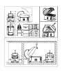
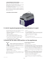
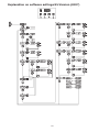
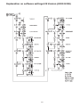
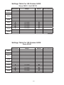
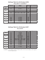
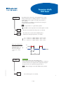
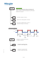
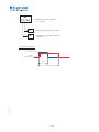
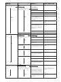
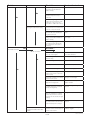
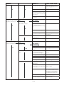
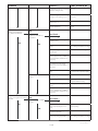
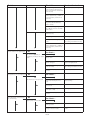
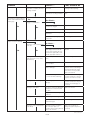
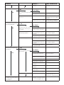
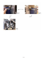
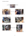
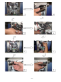
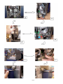
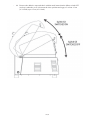
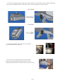
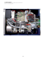
08/2010
HSG Panini
Service manual
Service Manual
GB
2
(50mm)
7,5
(190mm)
130 mm
2
(50mm)
This document is to be used in conjunction with the original manufacturer’s manual.
The symbols correspond with the numbered drawings of the original manual
GB
07/2009
Service Manual
Index
Short explanation of the appliance
List of required instruments for maintenance & repair
Check list for each intervention on the machine
Troubleshooting
Error codes
How to enter the Program mode
Explanation on software settings (logigram)
Settings table
Parameters
Repair section
Exploded View
1
4
4
5
6
6
7
8
10
20
A
1. Explanation of the appliance
1-1 IMPORTANT SAFETY INSTRUCTIONS
Carefully read this booklet as it gives important information
concerning safe maintenance.
Install or locate this appliance only in accordance with the
provided installation instructions
The following terms given in the service manual indicate a potentially hazardous condition for the operator, service personnel
or for the appliance.
• Danger! This term warns of an immediate danger that could
lead to considerable damage or death.
• Warning! This term indicates the potential risk of considerable damage or death following improper use or service of the
appliance.
• Important! This term indicates information that must be thoroughly understood, although not indicating danger.
Warning! Danger of fire.
For your safety, do not keep gasoline or other
flammable liquid or gaseous materials in the
vicinity of this or other appliances. Keep the
area around the appliance clear and free of combustibles. Do
not use this appliance in an explosive atmosphere.
Warning!
Only install the appliance in a well-ventilated
place. Inadequate ventilation causes asphyxia. Do not obstruct the ventilation system
of the place where the appliance is installed.
Do not obstruct the vent holes located at the
sides and back of this appliance.
Important!
Appliance installation and any maintenance work
must be carried out only by specialized personnel
authorized by the manufacturer. Install or locate
this appliance in a well-lit place.
• Place emergency telephone numbers in a visible position.
• For assistance, contact an authorized technical centre. Demand
original spare parts.
• This appliance is designed for cooking food. It is intended for
industrial use. Any other use is to be considered improper
• The appliance can’t be used by handicapped people or children
but only by responsible and trained operators.
• Do not leave the appliance unattended when operating.
• Unplug the appliance in case of a fault or poor operation.
• Do not use products (even if diluted) containing chlorine (sodium
hypochlorite, hydrochloric or muriatic acid, etc.) to clean the
appliance. Do not use metal tools to clean steel parts or the glass
surface (wire brushes or Scotch Brite type scouring pads).
• Do not allow dirt, fat, food or other residue to form deposits
on the appliance.
• Do not wash the appliance with direct jets of water.
Failure to observe the above can compromise the safety of the
appliance.
Failure to observe the above invalidates the warranty.
HSPP tech GB 03 09
1/38
WARNING
TO REDUCE THE RISK OF BURNS, ELECTRIC SHOCK, FIRE, INJURY TO PERSONS, OR EXPOSURE TO
EXCESSIVE MICROWAVE ENERGY:
1) Do not use the appliance empty
2) Read and follow the specific «PRECAUTIONS TO AVOID POSSIBLE EXPOSURE TO EXCESSIVE MICROWAVE ENERGY»
found in chapter 3 of the user manual
3) This appliance must be grounded. Connect only to properly grounded outlet. See «GROUNDING INSTRUCTIONS» found
on chapter 2-9 of the user manual
4) Install or locate this appliance only in accordance with the provided installation instructions
5) Some products such as whole eggs and sealed containers - for example, closed glass jars - are able to explode and
could not be heated in this appliance.
6) Use this appliance only for its intended use as described in the user manual. Do not use corrosive chemicals or vapours in this
appliance. This type of appliance is specifically designed to heat or cook FOOD. It is not designed for laboratory use.
7) As with any professional appliance, it can not be used by handicapped people or children.
8) Do not operate this appliance if it has a damaged cord or plug, if it is not working properly, or if it has been damaged
or dropped.
9) This appliance should be serviced only by qualified service personnel. Contact nearest authorized service facility for
examination, repair, or adjustment.
10) Do not cover or block any openings on the appliance.
11) Do not store this appliance outdoors. Do not use this product near water - for example, near a kitchen sink, in a wet
basement, near a swimming pool, or similar locations.
12) Do not immerse the appliance, the upper heating plate, cord or plug in water.
13) Keep cord away from heated surfaces.
14) Do not let the cord hang over the edge of a table or counter.
16) To reduce the risk of fire in the heating cavity:
I) Do not overcook food. DO NOT place plastic, or other combustible materials, cooking utensils or other item in all
materials it could be inside the appliance. ONLY FOOD, with the designated specific baking paper.
II) If materials inside the appliance ignite, turn appliance off, and disconnect the power cord.
III) Do not leave things on the glass, do not use the cooking chamber for storage purposes. Do not leave paper products,
cooking utensils, or food in the cavity when not in use.
IV) Do not put metallic recipient or any kind of kitchenware, tools.
V) Clean regularly the glass and the upper heating plate. Carbon deposit could overheat the food.
18) The maximum height of the food to be cooked must not overpass 3’’/75mm.
19) In use and after use the appliance risks to have hot surfaces, be aware of touching the appliances (especially all the
lid and its heating plate, the glass…).
20) As in any Microwave appliance, it can occur to have sparks inside the cooking chamber. These sparks do not influence
the safety of the user nor the appliance nor the quality of the food. If, as a consequence of the sparking, a dark mark on
the metal parts is visible, this can be cleaned with a damp cloth.
SAVE THESE INSTRUCTIONS CAREFULLY FOR FURTHER CONSULTATION BY THE VARIOUS OPERATORS
HSPP tech GB 03 09
2/38
PRECAUTIONS TO BE OBSERVED BEFORE AND DURING SERVICING TO
AVOID POSSIBLE EXPOSURE TO EXCESSIVE MICROWAVE ENERGY
(a) Do not operate or allow the appliance to be operated with the lid open.
(b) Make the following safety checks on all appliances to be serviced before activating the magnetron or other microwave source, and make repairs as necessary: (1) interlock operation, (2) proper lid closing, (3),contact surfaces (arcing,
wear, and other damage), (4) damage to or loosening of hinges and latches, (5)
evidence of dropping or abuse.
(c) Before turning on microwave power for any service test or inspection within
the microwave generating compartments, check the magnetron, wave guide or
transmission line, and cavity for proper alignment, integrity, and connection.
(d) Any defective or misadjusted components in the interlock, user interface,
contact surfaces, and microwave generation and transmission systems shall
be repaired, replaced, or adjusted by procedures described in this manual before the appliance is released to the owner
(e) A microwave leakage check to verify compliance with the standards should
be performed on each appliance prior to release to the owner.
HSPP tech GB 03 09
3/38
1-2 EXPLANATION OF THE APPLIANCE:
The appliance is a product specifically designed for Hot Sandwich
Outlets, with the following main characteristics:
• Great tasting, hot, toasted Sandwich in about less than 60”
(depending on the sandwich), in a one-step-solution;
• Combining the quality of latest Panini Grill technology with the
speed of Micro-Wave Technology;
• The HSG has been designed to be installed in many different
kinds of environment, even outside a real professional kitchen or
when the cooking activity is done in front of the customers (or at
least in the same room);
1-3 PICTURE OF THE APPLIANCE
2. List of required equipment for maintenance & repair
The following instruments and tools must be available for servicing
the appliance additionally to the regular equipment:
- MW leakage detector suitable for UL requirements (sensibility
0.1mW/cm2).=> 0D6887
- Multimeter => 0S0479
- Torx screw drivers sizes 18, 20 and 25.
- Surface contact temperature probe (min 300°C/572F).
In case of repair the following materials may be necessary:
- Conductive paste (for min 280 °C) => 049196 (100gr)
- Silicone RTV 102 color white. => 0D6886
- Silicone RTV 108 color transparent. => 0D1250
- Acetona.
- Glue: Loctite (Strong version).
- Test load for MW leakage: 1 quart/1 liter of tap water in a high
temperature and MW proof container . (Note the height of the
container cannot be more than 3”/75mm).
- Specific Glass cutting device. => 0D6888
- Cutter.
- Tool for smoothening a silicon rod.
- Positioning Jig ( only on demand for Authorized Repair Centres).
3.Check list for each intervention on the appliances
Important!
Appliance installation and any maintenance work
must be carried out only by specialized personnel
authorized by the manufacturer. Microwave leakage must be checked every time you do service
to the machine.
For the safe and efficient use of the appliance it is recommended
to check at each intervention the following issues.
- General integrity and cleanliness of the appliance
- Microwave leakage
- Right Functioning of the appliance
The following check list can be used also as guideline for every
preventive maintenance. Please refer to the after sales dealer
policy for more information.
General integrity and cleanliness
Unplug the appliance!
Verify that the machine is cooled down!
As in any Microwave appliance, it can occur to have sparks inside
the cooking chamber. These sparks do not influence the safety
of the user nor the safety of the appliance nor the quality of the
food. If, as a consequence of the sparking, a dark mark on the
metal parts is visible, this can be cleaned with a damp cloth.
If it is necessary to train the user on the cleaning, refer to the
cleaning instructions on pages 3 and 4 and chapter 5 in this
handbook.
a) Check the location (see installation diagram in page 15)
- Distances to other machines, walls and combustible parts
- Obstacles for the opening and closing action
- Obstacles on vent holes of the appliance
- Overall cleanliness of the surroundings of the appliance
- Check the used tools for cleaning . If not OK, advise the
user.
HSPP tech GB 03 09
4/38
b) Check the mechanical condition of the appliance
Glass:
- Cracks of the glass.
- State of the silicone sealing around the glass.
- Good position of the insulating parts inside the launching
chamber.
- Check the glass for heavy dirt.
Upper heating plate:
- Smooth movement of the upper heating plate, no noise.
- Easy removal of the upper heating plate.
- Check the presence and tightness of the screws of the cover
of the upper heating plate.
- Check the state of the upper plate cable and the tightness of
the connector to the column of the upper heating plate.
- Cleanliness of the upper cooking chamber.
- Easy plug-in of the upper heating plate with easily locking it
- Cleanliness of the upper heating plate, especially carbon
deposits and damages of the coating.
Upper lid:
- Easy closing and opening of the lid, no noise and no unusual
forces.
- Open the front cover and check the cleanliness of the steam
evacuation chamber.
Remove all particles stuck the grid.
Handle:
- Easy movement of the handle. Limiter screw must be in
place.
- Easy movement of the 2 pins in the handle and its automatic
repositioning.
- Check the tightness of the 2 pin blockers.
- Easy movement of the electromagnet washer.
- Cleanliness of electromagnet washer.
Front of the appliance:
- Cleanliness of the electromagnet.
- Good and tight position of the flat panel (membrane).
- Check for a big gap between front panel and electro magnet
support.
- Repair or renew the parts, if necessary.
Sides of the appliance
- No blocking of the ventilation holes.
Back of the appliance.
- No blocking of the exhaust holes.
- Check the silicone sealing on the top of the tilting box.
Cable connections (unplugged).
- Check the main power supply cord concerning damages,
burnings etc.
Microwave leakage
Go to this test only if the above described “General integrity and
cleanliness” test was passed!
Prepare and switch on your Microwave Detector (see “List of
required instruments for maintenance & repair” in chapter 2 of
this manual).
Press the two outer program buttons in the same time you plug
in the machine until that you see P1 on the display. (This testing
mode give the possibility to start the microwave cycle without
waiting the end of the preheating mode).
Put the specified load (see
for maintenance & repair” in
onto the glass and close the lid.
“List of required instruments
chapter 2 of this manual)
Start the leakage test immediately (the detector probe must be
at 5cm from the tested part perpendicular to it, verify the position
of your probe inside the detector):
- In front of the appliance horizontally along the gap between
lid and front panel.
- On both sides of the appliance horizontally along the gap
between lid and lateral covers.
- On the back of the appliance horizontally along the gap between
lid and tilting box.
- On the top of the appliance all around the column and the
upper plate cable.
- Inside the steam evacuation chamber (front cover removed!)
Warning: If the limit of 1.0 mW/cm² or 60V/m in the North
America and 5,0 mW/cm2 or 300V/m in Europe is exceeded for more than 3sec at the same position, the appliance
has a microwave leakage and has to be stopped immediately.
(see ” Repair section” in chapter 5 of this manual).
Functioning of the appliance
As the appliance is still in the testing mode and might have not
the right temperature, the appliance has to be switched off and
disconnected from the power supply.
The functioning test has to be executed as follows:
Connection to power supply.
- Verify the version of the User Interface.
Switch on and preheating
- Switch on the appliance.
- Check the temperatures on the glass and on the upper heating
plate.
- Try to push the program buttons (they should not be operational
during preheating).
During operation mode
- Start a cycle with the defined load.
- Check correct lid latching.
- Check automatic lid opening.
- Check cooking results (grilling of top and bottom as well as
core temperature in accordance with the chosen program if
using real load.
- Check all other programs.
For all findings please refer to the “troubleshooting” or the “repair
section” in chapter 4 resp. 5 in this manual.
4. HSG troubleshooting
For a fast and efficient, but also safe elimination of a potential
problem with the appliance, the trained service personnel can
use the following troubleshooting guide.
See the important safety information in Chapter 1 of this service
manual before any intervention on the appliance.
The troubleshooting guide has been set up in such a way that
the real cause behind the problem identified can be found by
going through the troubleshooting guide step by step from the
beginning.
Important!
Appliance installation and any maintenance work must
be carried out only by specialized personnel authorized by the manufacturer. Microwave leakage must be
checked every time you do service to the machine.
HSPP tech GB 03 09
5/38
Error codes
ERROR CODES
DESIGNATION
Err 1
Bottom probe
Err 2
Top probe
Err 3
Overheating HV transformer
Err 4
Front magnetron circuit problem
Err 5
Rear magnetron circuit problem
Err 6
Both magnetrons circuit problem
How to enter the Program mode
Unplug the machine. Plug the machine and simultaneously press buttons 2 and 3 to enter the program mode. ( BASI for EU model and
PRO for US model )
See the program mode diagram for the details.
List of settings :
Temp: temperature in C° or F°.
trt :
temperature of the upper heating plate
trb :
temperature of the bottom plate
tCYx: times corresponding to cycle x (1 2 3/4 S)
tt :
total time of the cycle
tw:
time of micro wave during the cycle
Action on buttons :
A:
enter in the setting
B:
decrease the value of the setting
C:
increase the value of the setting
D:
skip to the following parameter
HSPP tech GB 09 09
6/38
Explanation on software settings EU Version (U207)
7/38
Explanation on software settings US Version (U202-U208)
8/38
Settings Table For US Version U202
Since 09061 - Until 09122
Parameters
Range
Default
Duty
t1
t2
10s - 60s
1s - 30s
30
12
MF
Stby
t3
t4
t5
t6
0s - 30 s
5 min - 60 min
1 min - 10 min
10s - 3 min
10
60
240
60
Temp
trt
trb
Tcy1
tt
Tw
1s - 5 min
0s - 5 min
45
45
Tcy2
tt
tW
1s - 5 min
0s - 5 min
60
52
Tcy3
tt
tW
1s - 5 min
0s - 5 min
90
75
Tcy4
tt
tW
1s - 5 min
0s - 5 min
30
20
New Parameters
150°C - 250 °C / 300°F - 482°F 240°C / 464°F
150°C - 280°C / 300°F - 536°F 246°C / 475°F
Settings Table For US Version U208
Since 09061
Parameters
Range
Default
Duty
t1
t2
10s - 60s
1s - 30s
30
12
MF
t3
t4
t5
t6
trt
trb
tt
Tw
tt
tW
tt
tW
tt
tW
Stby
Temp
Tcy1
Tcy2
Tcy3
Tcy4
0s - 30 s
0
5 min - 60 min
60
1 min - 10 min
240
10s - 3 min
60
150°C - 250 °C / 300°F - 482°F 240°C / 464°F
150°C - 280°C / 300°F - 536°F 233°C / 451°F
1s - 5 min
45
0s - 5 min
45
1s - 5 min
60
0s - 5 min
52
1s - 5 min
90
0s - 5 min
75
1s - 5 min
30
0s - 5 min
20
9/38
New Parameters
Settings Table For EU Version U206
Since 09131 - Until 09191
Parameters
Range
Default New Parameters
Duty
t1
t2
10s - 60s
1s - 30s
30
12
MF
Stby
t3
t4
t5
t6
0s - 30 s
5 min - 60 min
1 min - 10 min
10s - 3 min
10
60
240
60
Temp
trt
trb
150°C - 250 °C / 300°F - 482°F
150°C - 280°C / 300°F - 536°F
250
230
Tcy1
tt
Tw
1s - 5 min
0s - 5 min
30
20
Tcy2
tt
tW
1s - 5 min
0s - 5 min
40
30
Tcy3
tt
tW
1s - 5 min
0s - 5 min
50
40
Tcy4
tt
tW
1s - 5 min
0s - 5 min
59
0
Settings Table For EU Version U207
Since 09131
Parameters
Range
Duty
t1
t2
10s - 60s
1s - 30s
30
12
MF
t3
t4
t5
t6
trt
trb
tt
Tw
tt
tW
tt
tW
tt
tW
0s - 30 s
5 min - 60 min
1 min - 10 min
10s - 3 min
150°C - 250 °C / 300°F - 482°F
150°C - 280°C / 300°F - 536°F
1s - 5 min
0s - 5 min
1s - 5 min
0s - 5 min
1s - 5 min
0s - 5 min
1s - 5 min
0s - 5 min
10
60
240
60
250
230
30
20
40
30
50
40
59
0
Stby
Temp
Tcy1
Tcy2
Tcy3
Tcy4
Default New Parameters
Comments : The modification between U206 and U207 concern only the display for the Program 4.
PS is now replace by P4
10/38
Parameters details
HSG Panini
DUTY
Regulation of the temperature of the bottom plate except
during standard cycle (a cooking program is selected, the
display shows Px, the upper lid is open, the machine is
not in Std By).
The temperature regulation is not in this cycle managed
by probe but by time (on/off).
The Upper Plate T˚ is regulated by a probe.
info Î the maxi temperature of cut of the probe is 250˚C.
T1
Total time of a period in the duty cycle (in seconds).
T2
Time where the resistance of the bottom plate is
switched on during the period T1 (in seconds).
T2 = 12 with T1 = 30 ÎT˚ bottom ≈ 250˚C / 482 F
T2 = 11 with T1 = 30 ÎT˚ bottom ≈ 235˚C / 455 F
T2 = 10 with T1 = 30 ÎT˚ bottom ≈ 220˚C / 428 F
Duty cycle chronogram :
on
Management of the
temperature of the bottom
plate except during the
cooking cycle or Std By
mode
Î
off
T2
T1
M.F.
Forcing time
Time at the beginning of each cooking cycle
during which the resistance of the bottom plate is in forced
on time to decrease the impact of the temperature drop of
the glass because of a panino being placed on it.
CUSTOMER SUPPORT - 2009/06
If too much high, risk of dark bottom of the panino.
T3
Time of forcing time (in seconds).
1
11/38
Std By
Energy save mode
Mode in which the machine can be set to decrease the
electrical consumption. In this mode, the ernergy save
mode is made by a control of temperature by time on/off
of the lower resistance
T4
Time before Std By (in minutes)
T5
Total time of a Std By period (in minutes)
T6
Time where the bottom plate resistance is
switched on during T5 (in minutes).
Std By cycle chronogram :
on
off
Tcy
Standard cooking
cycle
Tcy
T4
Time before Stby
cooking cycle
T4
OMER SUPPORT - 2009/06
Temp
Temperature regulation of the lower
and upper resistances
Trt
Temperature regulation of the
resistance and the upper plate
Trb
Temperature regulation of the
resistance and the lower plate
12/38
T6
T6
T5
T5
Tcy
1/2/3/4
Cooking cycle time regulation
1 - 2 - 3 and 4
Tt
Total time of the cycle in seconds
Tw
Microwaves time during the cycle
total time
Tcy cycle chronogram :
on resistance + mw
off mw
off resistance
Tw
OMER SUPPORT - 2009/06
Tt
13/38
Problem
Check if …
The unit doesn’t power up
Yes
no LED light on beside the
ON/OFF switch button
No
No
Yes: Check ...
plug is inside the socket
plug in
circuit breaker is on
re-engage
voltage arrives to the outlet
problem not related to the unit
voltage arrives to the terminal block
: US version: 208V between L and N
CE version: 400V between all
phases and 230V between L3 and
N on the filter
replace the cable and cord
wires are hooked in the terminal
block
fix the wires following the electrical
diagram
voltage is coming into the PCB with
a voltmeter : 208V between 121
and 122 on the connector 12 on the
board - CE version : 230V between
121 and 122 on the connector 12
on the board
reconnect or replace the cable if
damaged
the LED doesn’t work
replace the board
no initial display of “init” and “UIxx”
The unit doesn’t go in preheating Yes
replace the board
Yes: Check ...
membrane is in place and not
damaged
change the membrane
button is not damaged
change board
position between the board and the
membrane is OK
reposition the board or the membrane
No preheating mode indication
in the display
KM1 is working by visually checking
if the indicator moves from the initial
position and the power coming in
reconnect the wires or replace the
contactor
Indicates Error Codes Err1
the bottom probe is well connected
reconnect the probe
The value of the resistance of the
probe is approximately 1,1KOhm at
room temperature (1,074 Kohm at
25°C/77°F)
replace the probe
the top probe is well connected
reconnect the probe
the wiring extension of the top plate
probe is well connected
reconnect the wires
The value of the resistance of the
probe is approximately 1,1KOhm at
room temperature (1,074 Kohm at
25°C/77°F)
replace the probe
On/off button is blocked (no
«click»)
No
No
Indicates Error Codes Err2
Yes
The unit never reaches operating
mode
If not, action to do
Yes: Check ...
The top plate temperature is not
reaching the temperature setting
No
cabling of the upper plate to the terminal block, is connected , check also
connection between terminal block
and power board => connector 5 on
position 5 on the board + continutity
test between terminal block and board
the probe connector SUP is connected
in position SUP on the board ( lumberg
black connector).
HSPP tech GB 03 09
14/38
connect the wires in the good
position on terminal block and on
the board.
connect the connector SUP on the
board
Problem
No
No
The bottom plate temperature is not
reaching the temperature setting
The lid doesn’t latch
Yes
Check if …
If not, action to do
the top heating element is absorbing current with the Multimeter
(approx. 4amps)
replace the upper plate kit
cabling between terminal block
and the board (connector 5) is
connected
connect the wires
the board is not giving power to the
heating elements through the relay
(voltmeter in connector 5 of the
board, 208 V - 230V for CE version)
replace the board
cabling of the bottom plate to the
board, connector 4 is connected on
position 4 on the power board.
connect the wires
the probe connector INF is connected
in position INF on the board ( lumberg black connector.
Connect the connector INF on the
board
the bottom heating element is absorbing current with the Multimeter
(approx. 4amps)
replace the heating element of the
bottom plate
the board is not giving power to
the heating elements through the
relay (voltmeter in connector 4 of
the board)
replace the board
Yes: Check ...
The lid never latch
No
No
the lid doesn’t latch after some
cycles but restart to latch after
a while
the handle reaches the right position to the electromagnet
remove all obstacles and/or check
for mechanical frictions
the electromagnet and/or the
washer are dirty
make a proper cleaning
if the handle magnets are in place
replace the handle
the handle pins are blocked
try to unblock or replace the handle
screw of the washer is tight
readjust the latching system
cables of the electromagnet and
magnetic detectors are connected
(Connector 10)
connect the wires
electromagnet is working by a continuity
test from the connector 10
change the electromagnet
from connector 10 there is nominal
voltage when closing the lid
replace the board if the power
supply is suitable
magnetic detectors are working by
a continuity test from the connectors
14/15 (by closing the lid)
readjust or change the magnetic
detectors
the bimetallic sensors (CLK1 and
CLK2) are working by a continuity
test from the pins of the connector
3 (from the two left and the two right
contacts)
change the bimetallic sensor failed
KS1 is working by visually checking
if the indicator move from the initial
position and the power coming in
reconnect the wires or replace the
contactor
there is enough free clearance for
the airflow from the exhaust pipes in
the rear of the machine
give the clearance according to the
installation diagram
15/38
HSPP tech GB 03 09
Problem
No
The lid doesn’t open automatically at the end of the cycle
No
Check if …
If not, action to do
there is an airflow from the exhaust
pipes in the rear of the machine
reconnect the exhaust pipes to the
exhaust pipes support or remove
possible clogging obstacles inside
the pipes
the fan cabling is connected
reconnect the wires of the fan
there is power supply on both
magnetron fans (connector 7 on the
board - from the two left and the two
right contacts)
replace the board
the magnetron fans are working with
an ohmmeter
replace the broken fan
Yes: Check ...
Yes
the handle is moving
No
there is free movement by verifying:
- the opening of the lid
- no friction between lid and working
top
assure free movement
the handle pins are pushing out
try to unblock or replace the handle
lid springs are lifting the lid
adjust the spring tension or replace
them if broken
there is free movement between
handle and the lid
assure free movement
electromagnet is releasing the
handle at the end of the cycle
replace the board
No
the handle is blocked
Panino doesn’t reach the
desired core temperature
Yes
Yes: Check ...
No Error codes
No
No
Indicates Error Codes Err4 or
Err5
Indicates Error Codes Err6
the right program was chosen
use the right one
the programs have the right parameters
set the right parameters
high voltage wiring from the
secondary of transformer are well
connected and not damaged
reconnect them or replace if
damaged
the magnetron fuses are working
replace them
capacitors are undamaged
replace it
diode and resistor are undamaged
replace them
Result: Magnetron is broken
replace following the error code
The voltage to inlet is at least 1956V
for 208V machine and 367V for a
400V machine.
problem not related to the unit
the three phases are correctly
connected in the main plug. ( for
EU machines )
Connect the wires to have three
phases + neutral.
If the fuse FS of the board is OK.
replace the fuse FS with the spare part
fuse on the board and before restart
the machine check the adjsutment of
Microswicth S3. => Follow the process indicated in the repair section
screw of the washer is tight
readjust the latching system
if the handle magnets are in place
replace the handle
HSPP tech GB 03 09
16/38
Problem
Panino is not grilled on
the bottom as desired
Check if …
If not, action to do
magnetic detectors are working by
a continuity test from the connectors
14/15 (by closing the lid)
readjust or change the magnetic
detectors
KS2 is working by visually checking
the light on when starting a cycle
reconnect the wires or replace the
static relay
switch breaker of the primary
transformer is on
reactivate it
if both magnetrons are working like
described in Err4or5
proceed like described under
Err4or5
Yes
Yes: Check ...
Panini has no marks on
the bottom
No
No
Panini is overcooked on the
bottom
Panino is not grill on the top as
desired
Yes
The bottom resistor is working
(«orange color»)
proceed
the programs have the right parameters
set the right parameters see the
brief cooking result trouble shooting
the resistor wiring is connected and
not damaged
reconnect or replace if damaged
The value of the resistance of the
probe is approximately 1,1KOhm at
room temperature (1,074 Kohm at
25°C/77°F)
replace the probe
the board contact of connector 4
are supplying the right voltage :
208V for US version and 230V for
CE version
replace the board
the probe is well in contact with the
glass
recondition/deblock the spring system that hold the temperature probe
the bottom surface is cleaned (no
carbon deposits)
clean it
the right program was chosen
use the right one see the brief cooking result trouble shooting
the programs have the right parameters
set the right parameters
The value of the resistance of the
probe is approximately 1,1KOhm at
room temperature (1,074 Kohm at
25°C/77°F)
replace the probe
Yes: Check ...
The Panino has no marks on
the top
No
No
the upper plate can adjust to the
Panino automatically (free movement)
deblock the upper plate by cleaning
and/or repairing
The upper plate is working
(measure temperature)
proceed
the programs have the right parameters concerning temperature
set the right parameters see the
brief cooking result trouble shooting
HSPP tech GB 03 09
17/38
Problem
Check if …
If not, action to do
the resistor wiring 51 and 52 is
connected and not damaged (resistor to terminal block and terminal
block to board)
reconnect or replace if damaged
The value of the resistance of the
probe is approximately 1,1KOhm at
room temperature (1,074 Kohm at
25°C/77°F)
replace the probe
the top heating element is absorbing current with the Multimeter
(approx. 4amps)
replace it
the board is providing the right voltage : 208V for US version and 230V
for CE version
replace it
Panini is overcooked on the top the top surface is cleaned (no
clean it
carbon deposits)
Panino sticks to the upper plate
No
Yes
the programs have the right parameters
set the right parameters see the
brief cooking result trouble shooting
The value of the resistance of the
probe is approximately 1,1KOhm at
room temperature (1,074 Kohm at
25°C/77°F)
replace the probe
The Panino is partially or
completely sticking to the upper the upper plate or the used baking
paper is clean
plate
Yes
clean it
the upper plate or the used baking
paper is damaged
replace the baking paper or if necessary the total upper plate kit
the programs have the right parameters (T<250°C)
set the right parameters see the
brief cooking result trouble shooting
the load (Panino) is appropriate to
the HSG
avoid this type of load
Yes: Check ...
The Panino too much pressed
No
No
The upper plate is not removable for cleaning
use the right one
Yes: Check ...
No
The panino is too much pressed
the right program was chosen
the upper plate can adjust to the
Panino automatically (free movement)
deblock the upper plate by cleaning
and/or repairing
the Panino was placed correctly in
the work zone
train the user
the programs have the right parameters (time of MW)
set the right parameters
the load (Panino) is appropriate to
the HSG
avoid this type of load
Yes
Yes: Check ...
Upper plate not releasable
No
No
the release pin is blocked, so no
pushing possible
unblock the release pin
the release pin can not be pushed
enough to release the plate
readjust or replace the release
system
HSPP tech GB 03 09
18/38
Problem
Check if …
Upper plate releasable, but not there are obstacles for a free
removable completely from the movement
cooking chamber
the upper plate cable is free to
enter into the cooking chamber
The panino is soggy and/or too
much condensation around the
working top
If not, action to do
deblock the upper plate by
cleaning and/or repairing
deblock it or help manually to
enter
Yes
Yes: Check ...
Soggy or condensation
No
Visible mechanical damage
No
the steam outlet is free
deblock or clean it
the programs have the right
parameters
set the right parameters
the load (Panino) is appropriate
to the HSG
avoid this type of load
Yes
Damages on the external parts
of the lid
No
the ventilation grid in the front of clean it
the lid is not clogged
Yes: Check ...
the damage does not influence
MW leakage and mechanically
the use of the machine (free movement of the upper plate, of the
handle, upper plate cable etc.)
Repair or change the incriminated parts.
choke cover pins are all in
place
add the missing ones
sealing of the choke cover is in
good condition
reseal where needed
choke cover is in place and
without damages
Replace the choke cover.
Verify the choke for bendings/
damages.Readjust the strips
of the chokes. If not possible
replace the total lid.
all the surroundings of the choke cover are without damage
check for microwave leakage or
mechanical influences. Repair
or replace the lid if necessary
Damages on the working top
the working top is without
damage
check for MW leakage or
mechanical influences. Repair
or replace the working top if
necessary
Damages of the glass
the silicone rod is not damaged
or/and there is moisture below
the glass
replace the silicone
the glass is without damage or
scratches
replace the glass
the coating is not damaged
replace the total upper plate kit
upper plate cover is in place
and/or damaged
fix it or change if necessary
No
Damages on the internal parts
of the lid (choke cover, choke,
flat surfaces)
Damages of the upper plate
Damages on the external parts
of the body
front panel and/or membrane
replace the membrane or
are correctly in place (no
change the total front panel if
possible water reaching internal necessary
parts of the machine
HSPP tech GB 03 09
19/38
Problem
Abnormal noise
Yes
No
Noise during opening/closing
the lid
Noise permanent when machine is on
Check if …
If not, action to do
louvers are not clogged or
deformed
clean or change the part if
necessary
Yes: Check ...
lid springs don’t make noise in
movement
put some grease or cooking oil
transformer fan is free rotating
remove the obstacles, readjust
the position of the fan or replace
it if broken
magnetron fans are free rotating remove the obstacles, readjust the position of the fan or replace it if broken
The machine goes in preheating/cooling frequently
No
Yes
Yes: Check ...
the phenomenon raises after a
stdby mode or switching on of
the machine
the phenomenon raises suddently during operation
the unit also displays err3
Automatic lid opening doesn’t
work properly
No
adjust it
there is enough free clearance
on the lateral sides for the cooling airflow
give the clearance according to
the installation diagram
there is an air sucktion flow on
the right lateral side
clean the louvers
the fan is working
reconnect the wires of the fan or
replace the fan
there is enough free clearance
on the lateral sides for the cooling airflow
give the clearance according to
the installation diagram
there is an air sucktion flow on
the right lateral side
clean the louvers
Yes
lid doesn’t arrive or stay in full
open position
lid opens too fast
Error 4 or 5 is indicated, but
the Panino reaches the desired
core temperature
the the stdby parameter is according customer expectation
Yes: Check ...
the lid has a free movement
remove the obstacle
springs are both in place and
not broken and well adjusted
adjust or replace them
gas spring is in place
adjust or replace it
spring support is not broken
replace it
axis is not broken and not
deformed
replace it
tube is not broken and not
deformed
replace it
the bushings are not broken
and are in place
adjust or replace it
screws of the tube axis are tighted
tighten them
springs are both well adjusted
adjust them by having a pretension
enough to lift the lid of 19cm on the
front without the gas spring working
the amperometric transformer is
replace it
working by measuring the Voltage
on connector TM (approx. 3V)
HSPP tech GB 03 09
20/38
4-1 COOKING RESULT TROUBLE SHOOTING
QUALITY COOKING OF THE SANDWICH
If the sandwich is not enough or to much cooked try another program.
If there is no adequate program follow the trouble shooting here above:
FINDINGS
WHAT TO DO
The core temperature of the sandwich is
too cold
- Increase the time of microwave (tw)
- If the time of microwave tw is more than the
total time (tt), increase also the total time (tt).
The core temperature of the sandwich is
too hot
Decrease the time of microwave (tw)
The top of the sandwich is burned
Decrease the upper heating plate temperature (trt) and (or) decrease the total time
(tt).
The top of the sandwich is not enough
cooked
Increase the upper heating plate temperature (trt) and (or) increase the total time
(tt).
The bottom of the sandwich is burned
Decrease the bottom glass temperature
(trb) and (or) decrease the total time (tt).
The bottom of the sandwich is not enough
cooked
Increase the bottom glass temperature (trb)
and (or) increase the total time (tt).
warning :
- the temperature of the upper heating plate
is the same for the 4 programs.
- the temperature of the bottom glass is the
same for the 4 programs.
5. Repair section
Important!
Appliance installation and any maintenance work
must be carried out only by specialized personnel
authorized by the manufacturer. Microwave leakage
must be checked every time you do service to the machine.
In this chapter you will find the description of the necessary
work to do in case the appliance has to be repaired. Please
refer to the after sales dealer policy for more information on the
repairing activities.
Make sure to follow all general safety instructions concerning
repairing electrical appliances.
There are 2 ways to access the internal parts of the appliance:
by dismounting the bottom plate and by dismounting the back
panel of the tilting box.
In any case, do not open the appliance in total, i.e removing
both side panels at the same time. In doing so, all adjustments
of the appliance will be lost and the appliance is unusable. Only
the specific Authorized Repair Centres are able to make proper
adjustments with special tools.
Make sure to access the machine using the right way, which is
indicated in the following descriptions.
Make sure to follow all specific safety instruction concerning this
appliance (see Chapter 1.1 of this manual).
5-1 CHANGE THE PROBE OF THE BOTTOM
RESISTOR
This is not possible by every technician! Only in Authorized
Repair Centres.
Switch off and disconnect the machine.
Unscrew the tilting box with the lid (item S30 articulation exploded
view and 47 in cover exploded view).
Return the appliance on its back and position it in the jig.
Remove the bottom plate (Item 27 on the housing exploded
view).
Remove the front panel (Item S11 on the housing exploded
view).
Remove the two lateral sides (Items 20 and 22on the housing
exploded view).
Disengage the two springs (Item 4 on the Launching Chamber
exploded view).
Remove the washers and the cylindrical spring (Items 5 and 6
on Launching Chamber exploded view).
Remove the launching chamber (item 9 launching chamber
exploded view).
Disconnect the probe cable in the board.
Take out the probe and replace with a new one.
Reassemble the appliance.
Warning! Remember to position and fix the tilting box with the
core part of the appliance still in the jig (this will keep the correct
position between the lid and the working top).
21/38
5-2 REPLACE THE TOTAL UPPER PLATE KIT
Switch off and disconnect the machine.
Open the back panel of the tilting box ( items 100 and 101 on
articulation exploded view ).
Disconnect the 3 wires (small terminal block and the Lumberg
connector of the probe).
Unscrew and remove from the tilting box the upper plate cable
(item 40 on the cover exploded view ) connector ( item 98 on
articulation exploded view ).
• Put a protection (e.g. clothes, silicon liner) on the glass surface.
• Hold the lid down with one hand and unlock the upper heating
plate by pushing the button ( item 41 on the cover exploded
view ).
• Open the lid carefully and take care that the upper heating
plate removes out of the cooking chamber (in fi nal position the
upper heating plate stands on the glass).
5-3 REPLACE THE HEATING ELEMENT OF THE
BOTTOM PLATE
Switch off and disconnect the machine.
Remove the glass (Item 1 on the working top exploded view) by
cutting the silicone seal with the glass cutting device (see list
of required tools).
Remove the front panel (items 28 and 30 in the housing exploded view).
Remove the electromagnet support (Item 33 on the housing
exploded view) by unscrewing the 2 screws and the 2 nuts.
Disconnect the 2 wires connected to the resistor .
5-4 READJUST THE LATCHING SYSTEM
Remove the black cap on the handle, and unscrew the nut.
Unscrew completly the screw in the washer ( item 58 of the lid
exploded view )
Check if the seal ( item 59 of the lid exploded view ) is in place
and in a good position. If not , place correctly or change it.
Screw the screw until that is in contact with the handle, then
make a half turn back.
Check if the latching system is working correctly. Pay attention that
Remove the complet upper plate kit including upper plate cable
( item S21 on the cover exploded view ).
Assemble the new upper plate kit :
Put the upper plate cable in the hole ( item S24 cover exploded
view )
• Check the position of the upper heating plate: FRONT symbol
to front and remount the upper heating plate by pushing the
column into the central guidance until the locking mecanism is
locked ( CLICK sound).
• Move up and down the upper heating plate to check the
correct functioning.
Reconnect the upper plate cable connector on the tilting box.
Rconnect the 5 wires.
Check the correct functioning by measuring the right T°.
Assemble the back panel of the tilting box.
Replace the machine in accordance with the installation diagram.
Unscrew the 2 nuts of the resistor.
Remove the resistor through the opened working top (glass
removed). Pay attention not to damage the other internal parts
like the probe tube and the probe!
Put in place the new resistor and fix it in using the 2 new nuts
Connect the 2 wires disconnected before.
Replace the electromagnet support and the front panel.
Pay attention that all wires are still well connected.
Put in the glass following the instructions written in chapter 5-7
(Replace the glass).
tha appliance has to be either in operation or in testing mode.
If not reajust the screw of the washer ( in small steps screw or
unscrew )
Check again and repeat if necessary until find the correct
position.
Maintain the screw with a screw driver and in the same time
block the opposite nut.
Put in place the black cap.
5-5 READJUST OR CHANGE THE MAGNETIC
DETECTORS
Switch off and disconnect the machine.
Make sure that the detector that has not passed the continuity
test is in the right position and correctly tight.
( see the following picture to determine the correct
position ).
If not: reposition it or tighten it.
If yes: replace it.
HSPP tech GB 03 09
22/38
5-6 REPAIR OR REPLACE THE CHOKE COVER.
Switch off and disconnect the machine.
If the choke cover is damaged, it must be replaced. Therefore:
- take out all choke cover pins by using a screw driver.
- cut the silicone sealing with a cutter (see list of required tools).
- remove the choke cover.
- clean all the contact surfaces with Acetone (see list of required
tools).
- Verify that the choke is in good condition (no bendings, damages.
- Readjust the strips of the choke, if necessary. If not possible,
replace the entire lid!
- Put the new choke cover on the choke.
- Press in all choke cover pins (Make sure to use the new pins
delivered with the choke cover).
- Seal the choke cover with a silicone rod and smoothen it with
the specific tool (see list of required tools).
- The concerned parts must not be touched and the appliance
must not be used for at least 8hours.
If one or more choke cover pins are missing:
- Replace the missing pins by new ones.
If the silicone rod of the choke cover is damaged or no more
complete:
- Clean the concerned area from old silicone rests by using a
cutter (see list of required tools).
- Clean all the contact surfaces with Acetone or regular primer
for RTV (see list of required tools).
- Renew the silicone sealing and smoothen it with the specific
tool (see list of required tools).
- The concerned parts must not be touched and the appliance
must not be used for at least 8hours .
5-7 REPLACE THE GLASS
Switch off and disconnect the machine.
If the glass is still in one piece:
Remove the glass (Item 1 on the working top exploded view) by
cutting the silicone seal with the glass cutting device (see list of
required tools in this manual)
If the glass is broken:
Remove the pieces carefully by using gloves to avoid cuttings
of the hand.
Remove all rest of silicone sealing on the working top.
Degrease the contact area of the working top with Acetone (see
list of required tools in this manual).
Place the new glass (item 1 on launching chamber exploded
view) on the working top.
Seal the glass with a sealing rod between the glass and the
working top (be carefull to fill the entire gap also underneath the
glass). Use the specific tool to smooth the silicon rod.
5-8 ADJUST THE SPRINGS (See page 23)
Switch off and disconnect the machine.
Open the back panel of the tilting box ( items100 and 101 on
articulation exploded view ).
Disengage the gas spring (item 88 on articulation exploded
view) on one of its ends.
Adjust the springs (item 86 on articulation exploded
view) in the way that their pretension lifts the lid 130mm
+/- 10mm (5,1’’+/-0,4’’) on the front without the gas
spring working.
Reengage the gas spring.
Make a functioning test of the lid opening.
Reinstall the back panel of the tilting box.
(See page 23)
5.9 CHANGE THE GAZ SPRING (see page 26)
HSPP tech GB 09 09
23/38
130mm
190+/- +/- 10mm
(5,1’’+/-0,4’’)
10mm
ADJUST THE SPRINGS :
HSPP tech GB 03 09
24/38
HSPP tech GB 03 09
25/38
26/38
5.9 CHANGE THE GAS SPRING
27/38
28/38
29/38
5-10 ADJUST THE MICROSWICTH S3 :
Adjustment of the micro switch S3
Composition of the kit 0D7003 :
-
1 micro switch support
4 washers M4
2 screws M4
List of tools necessary to repair
-
Screwdriver with Torx T20 socket
Ratchet handle with M 7 socket
Screwdriver for M3
Wrench 7mm or socket 7mm
Multi meter with a BIP function for continuity and 2 holders
Adhesive tape
Steel Rule or equivalent
30/38
31/38
-
5 Remove the micro switch and mount
it on the new support .
This operation is mandatory
(Screwdriver for M3 and
Wrench 7mm or socket 7mm)
-
6 Mount 2 washers M4 on the welded
screws of the tilting box
-
7 Mount the micro switch support
The wheel must touch the aluminium axis
Mount 2 washers M4
Mount the 2 nuts delivered in the kit
Tighten the nuts by hand
32/38
-
8 Move the machine upward and put
an adhesive tape in order to maintain
a gap of 16cm (6.1/4 inch) between
the front of the cover and the top cooking surface
-
9 connect the multi meter on the micro switch
and select the BIP continuity function
-
10 Adjust the micro by pushing it slowly
in direction of the aluminium axis until
the BIP stops
Tighten the nuts (Ratchet handle with
M 7 socket)
33/38
-
11
Remove the adhesive tape and check with the multi meter that the Micro switch OFF
(no beep) when the cover is between the close position and a gap of at least 12 cm
(4.3/4 inch) up to 17cm (6.3/4 inch).
34/38
- 12 Check visually the position of the micro switch wheel to be sure that the wheel is all time align with
the cam on the aluminium tube. Check this with cover in open position, in close position.
Cover closed
Cover open
- 13 Connect the multi meter on the micro switch and
select the BIP continuity function.
- 14 Close the cover and make pressure on the handle,
in same time listen and check the multi meter to verify
if in this position the micro switch stay open circuit. (no beep)
35/38
onect the micro switch.
emount the rear cover.
es the unit 4 cycles minimum (warning : made the test only with load).
the standard procedure of check list after each intervention :
36/38
37/38
5-11 WIRES POSITION :
To don’t have disturbance in the cabling, respect the position of the
wires like on the following picture.
38/38


![10780-90006 - 10780A Laser Receiver for 5501A [Prefix 1948] (Mar](http://vs1.manualzilla.com/store/data/006009643_1-6e2f54ebb2199ef6df634558ba4c1bb6-150x150.png)