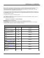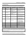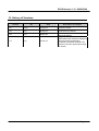
1
DCON-Version 1.10 –2005/05/06
Communication Driver DCON
Driver for serial communication (RS-232) and W-8x3x
embedded controller with ICP-DAS modules from the DCON
(I-7000, I-8000 and I-87K) families’ device
Index
1. Introduction................................................................................................................................. 2
2. General Characteristics ........................................................................................................... 3
2.1 Device Characteristics ....................................................................................................................... 3
2.2 Link Characteristics............................................................................................................................ 3
2.3 Driver Characteristics......................................................................................................................... 4
2.4 Information About Conformance Testing............................................................................................ 4
3. Installation ................................................................................................................................... 5
3.1 Installing the Driver ............................................................................................................................ 5
3.2 Other Software Requirements ........................................................................................................... 5
4. Driver Configuration ................................................................................................................. 6
4.1 Other Software Requirements ........................................................................................................... 6
4.2 Driver Worksheet ............................................................................................................................... 8
4.3 Station and Header configuration....................................................................................................... 9
4.4 Address Configuration...................................................................................................................... 10
4.5 Device Configuration.........................................................................................................................11
5. Execution ................................................................................................................................... 12
6. Application In W-8x36/W-8x39 (WinCE) Platform............................................................ 13
6.1 Creating a New Application for W-8x36/W-8x39.............................................................................. 13
6.2 Driver Configuration ......................................................................................................................... 15
6.2.1 I-8000 and I-87K Modules Plugged in WinCon Extension Slot............................................ 15
6.2.2 Distributive Controller of I-8000, I-87K and I-7000 Series Modules Through COM Port ..... 17
6.3 Download Application into W-8x36/W-8x39 ..................................................................................... 18
7. Improve DI/AI scan time......................................................................................................... 21
8. Troubleshooting....................................................................................................................... 23
9. Application Sample ................................................................................................................. 25
10. History of Versions ............................................................................................................... 26
Page 1
DCON-Version 1.10 –2005/05/06
1. Introduction
The DCON driver enables communication between Studio system and some of ICP DAS modules
from families DCON (I-7000, I-8000 and I-87K), in accordance with the characteristics covered in this
document.
This document contains 8 parts as follow:
Introduction: Provide an overview of the driver documentation.
General characteristics: Provide information necessary to identify all the required components
(hardware and software) necessary to implement the communication and global characteristics
about the communication.
Installation: Explain the procedures that must be followed to install the software and hardware
required for the communication.
Driver configuration: Provide the required information to configure the communication driver
such as the different permutations for configuration and its default values.
Execution: Explain the steps to test whether the driver was correctly installed and configured.
Troubleshooting: Supply a list of the most common error codes for this protocol and the
procedures to fix them.
Application Sample: Provide a sample application for testing the configuration the driver.
History of versions: Provide a log of all the modifications done in driver.
Note: This document presumes that the user has read the chapter Driver Configuration of the
Studio’s Technical reference manual.
Page 2
DCON-Version 1.10 –2005/05/06
2. General Characteristics
2.1 Device Characteristics
Manufacturer: ICP DAS
Compatible Equipment
-ICP DAS modules from families DCON (I-7000, I-8000 and I-87K).
Note: Please refer to section 2.4 to see the Equipment used in the standard conformance tests for this driver.
Note: All analog modules must be configured to engineering units.
Note: This Driver version does not implement the CRC. The equipment must be configured not to use CRC
check.
2.2 Link Characteristics
Device communication port: RS232 port
Physical protocol: RS232/RS485
Logic protocol: ASCII (Proprietary)
Device Runtime software: DCON driver
Specific PC Board: None
Page 3
DCON-Version 1.10 –2005/05/06
2.3 Driver Characteristics
Operation System:
- Windows XP
- Windows 2000
- Windows NT
- Windows CE (W-8x3x embedded controller)
Note:
Please refer to section 2.4 to see the Operating System used in the conformance tests for this driver.
The driver is composed of the following files:
DCON.INI: Internal files of the driver, it should not be modified by the user.
DCON.MSG: This file contains the error messages for each error code. It is an internal file of the driver,
and the user should not modify it.
DCON.PDF: This document provides detailed documentation about the driver.
DCON.DLL: This is the compiled library for the driver.
Note:
All the files above must be in the subdirectory /DRV of the Studio’s installation direction.
2.4 Information About Conformance Testing
Equipment:
Family I-7000: I-7060, I-7021 and I-7012D
Family I-8000: I-8040, I-8041, I-8024 and I-8017
Family I-87K: I-87054, I-87017 and I-87024
Configuration:
PLC program:
Baud Rate: 115200
Data Bits: 8
Stop Bits: 1
Parity: None
COM port: 1
Timeout: 200
Checksum: 0 (No Checksum)
Cable:
Operating System (development): NT/2000/XP
Operation System (target): NT/2000/XP
Studio Version: 6.0
Driver version: 1.10
Note:
Users can free download the test demo from the web site:
http://www.icpdas.com/products/software/indusoft/indusoft.htm
Page 4
DCON-Version 1.10 –2005/05/06
3. Installation
3.1 Installing the Driver
After install the InduSoft Web Studio (IWS) v3.0 or later version, the DCON driver of ICPDAS is not
installed in IWS. So before using the DCON driver in IWS, users need to install the DCON driver first. The
DCON driver setup file can be downloaded from ICPDAS web site:
http://www.icpdas.com/products/software/indusoft/indusoft.htm. When the DCON communication
driver is installed in IWS, users just need to select the driver in the application and the steps are described as
follows:
1. Execute the Studio and select the proper application.
2. Select the menu Insert + Driver….
3. In the column Available Driver, select the DCON Driver and push the button Select>> (the driver DCON
must appear in the column Selected Drivers)
4. Press OK.
3.2 Other Software Requirements
It is not necessary to install any other software in the PC to enable the communication between the host and
the Device.
Note:
Special cautions must be taken when installing the physical hardware. Refer to the hardware manufacture
documentation for specific instructions in this area.
Page 5
DCON-Version 1.10 –2005/05/06
4. Driver Configuration
After the driver is installed and selected in the Studio (see section 3.1), you should proceed to the driver
configuration.
The driver configuration is two parts:
The Settings or Communication parameters, they are only one configuration to the whole driver, and you
have the communication tables or Driver Worksheets, where the communication tags are defined.
4.1 Other Software Requirements
These parameters are valid for all driver worksheets configured in the system. To open the window for
configuring the Communication parameters, and follows these steps:
1. In the Workspace of the Studio environment, select the Comm table.
2. Expand the folder Driver and select the subfolder DCON.
3. Right click on the DCON subfolder and select the option Settings.
When selecting the Settings, these are the following dialog to configure:
Page 6
DCON-Version 1.10 –2005/05/06
4. Specify the parameters as noted in the following table:
Parameter
Default Value
Valid values
Description
COM
COM2
COM1 to COM256
Serial port of the PC/W-8x3x used to
communication with the device
Baud Rate
9600
110 to 115200bps
Communication rate of data
Data Bits
8
5 to 8
Number of data bits used in the
protocol
Stop Bits
1
1 or 2
Number of stop bits used in the
protocol
Parity
None
Timeout
200
Checksum
0
Even, odd, none, space or
Parity of the protocol
mark
0~2147483647
Time unit is 1 ms.
0 or 1
0: No checksum
1: Checksum
Note: These Parameters must be just the same as the configured on the ICP DAS device.
Page 7
DCON-Version 1.10 –2005/05/06
4.2 Driver Worksheet
It is possible to configure main driver worksheets and each one will be composed of a Header and Body. To
create a new driver worksheet, and follows these steps:
1. In the Workspace of the Studio environment, select the table Comm.
2. Expand the folder Drivers and select the subfolder DCON.
3. Right click on the DCON subfolder and select the option Insert.
Note: To optimize communication and ensure better performance for the system, it is important to tie the tags
in different driver sheets according to the events that must trigger the communication of each group of
tags and the periodicity for which each group of tags must be written or read. In addition, it is
recommended to configure the addresses of communication in sequential blocks.
When creating a communication table, you have the following window:
Caution:
Users can only apply the tag name up to 100 items in the same worksheet
Page 8
DCON-Version 1.10 –2005/05/06
All entries at the Driver Worksheet, exception by the Station, Header and Address are standard to all
communication drivers. You should refer to Studio Communication Driver documentation about the
configuration of the standard fields. This document describes the Station, Header and Address fields, which
are specific to each communication driver.
4.3 Station and Header configuration
Parameter
Default Value
Valid value
Station
Description
Not used
Header
AI
Define the type of variable to be read or
written from or to the device.
See next table
The Header field defines the type of variables that will be read or written from or to the device. It complies
with the syntax:<Module’s Type>. After editing the field Header, the system will check if it is valid or not. If the
syntax was incorrect, the default value (AI) will be automatically placed in the field.
You can type Tag between curl brackets into this field, but be sure that the Tag’s value is correct, with the right
syntax, or you will get the Invalid Header error.
Information regarding the parameter “Header”
Type
Sample of syntax
Valid range of
initial Address
Read Digital Input/Output
DI
Any
Read/Write Digital Output
DO
Any
Read Analog
AI
Any
The ICP DAS device channel must be
configured to engineering units
Write/Read Analog
AO
Any
The ICP DAS device channel must be
configured to engineering units
Read/Set Counter
Counter
Any
Read/Set DI Counter
value
DICounter
Any
Write Command
SendCmd
Any
Comment
Send command to the device
Note: Always creates two different driver worksheets to read Input and Output.
Page 9
DCON-Version 1.10 –2005/05/06
4.4 Address Configuration
The body of the driver worksheet allows you to associate each tag to its respective address in the device. In
the column Tag Name, you must type the tag from your application database. This tag will receive or send
values from or to the device.
The address cells complies to the following syntax:
For I-7000 and I-87K Family:
<Module’s Address>:<Module ID>:<Channel Number>
Module’s Address[Hex]: Module’s Address in the network (Range from 00 to FF)
Module ID: Module’s ID in the device
Channel Number: Channel’s Number to be read/written from/to the module.
Sample of Addressing Configuration
Address on the Device
Read I-87053 module Address 1
channel 0 (input)
Write/Read I-7063D module
Address 6 channel 1 (output)
Read I-7017R module Address 3
channel 6 (input)
Write/Read I-7021 module
Address 0x0A channel 1 (output)
Read/Set I-7080 module Address
7 channel 0 (input)
Read/Set I-7060D DI module
counter Address 5 channel 0
(input)
Write command to devices with
tag value
Header Field
Address Field
DI
01:87053:0
DO
06:7063:1
AI
03:7017:6
AO
0A:7021:0
Counter
07:7080:0
DICounter
05:7060:0
SendCmd
Not used
Page 10
DCON-Version 1.10 –2005/05/06
For I-8000 Family:
<Module’s Address>:<Module ID>:<Slot Number >:<Channel Number>
Module’s Address[Hex]: Module’s Address in the network(Range from 00 to FF)
Module ID: Module’s ID in the device
Slot Number: The slot number that the Module is plugged in the backplane.
Channel Number: Channel’s Number to be read/written from/to the module.
Sample of Addressing Configuration
Address on the Device
Read address 3 channel 0 of
I-8053 module in slot 1
Write DO to address 6
channel 2 of I-8064 module in
slot 4
Read AI from address 2
channel 5 of I-8017H module
in slot 6
Write AO to address 0x0A
channel 3 of I-8024 module in
slot 0
Header Field
Address Field
DI
03:8053:1:0
DO
06:8064:4:2
AI
02:8017:6:5
AO
0A:8024:0:3
Head Type
Support Modules
DI:
I-7011/12/14/16, I-7041/44/50/52/53/55, I-7060/63/65, I-8051/52/53/54/55/63 and
I-87040/87051/52/53/54/55/63
DO:
I-7011/12/14/16, I-7042/43/44/50, I-7060/63/65/66/67/80, I-8054/55/56/57,
I-8060/63/64/65/66/68, I-87041/54/55/56/57 and 60/63/64/65/66/68
AI:
I-7011/7012/7013/7014/7015/7016/7017/7018/7033,
8017H/ 87013/ 87016/ 87017/ 87018
AO:
I-7016/I-7021/I-7022/I-7024,
I-8024/ 87022/ 87024/ 87026
Counter:
I-7080
DI Counter I-7011/12/14/16, I-7041/44/50/52/53/55, I-7060/63/65 and I-87040/51/52/53/54/55/63
4.5 Device Configuration
The device parameter (baud rate, stop bits, etc) must be matched with the settings configured in the
Communication Parameters of the DCON driver.
Page 11
DCON-Version 1.10 –2005/05/06
5. Execution
When installing the driver, it is automatically selected to execute when you start-up the Runtime Environment.
To verify if the driver is correctly enabled and started, use the menu option Project + Status…., and verify the
task Driver Runtime.
Page 12
DCON-Version 1.10 –2005/05/06
6. Application In W-8x36/W-8x39 (WinCE) Platform
The W-8x36/W-8x39 is a leading edge embedded platform in Windows CE.NET with the Intel Strong ARM
CPU. It can operate as an intelligent distributed data acquisition front end connected to Host machine running
a standard SCADA package. The users can develop SCADA applications in a PC, and then download and
apply them on the W-8x36/W-8x39 InduSoft Embedded Controller. The application procedure is the same as
the description of the above section. Here, we will explore the design steps for W-8x36/W-8x39 only. If users
need more detailed information about how to build and design a project, please refer to the above section or
InduSoft Web studio user manual.
6.1 Creating a New Application for W-8x36/W-8x39
Users must choose Windows CE target system in creating a New Project. There are many kinds of target
systems in InduSoft for you as following table:
Target System
Product License
CEView Lite
150 tags; Runtime for WinCE
CEView Lite Plus
300 tags; Runtime for WinCE
CEView Standard
1500 tags; Runtime for WinCE
CEView PRO
4000 tags; Runtime for WinCE
Follow the procedure to create a new IWS application:
1. Select File→New from the InduSoft Web Studio main menu bar.
2. When the New dialog appears, click on the “Project” tab.
Page 13
DCON-Version 1.10 –2005/05/06
3. Set the name of your application in “Application” field (For this example, we set “GetStart”).
IWS would automatically create a new directory of the same name and assign your application file to
that directory (Refer to the “Configuration” field in the previous figure). To put your application file other
than in the \Projects subfolder of InduSoft Web Studio, and click Browse to navigate to the preferred
directory location.
4. Select a platform from the Target Platform list (For this example, select “CEView Lite Plus”), and click
OK to proceed.
5. When the Project Wizard dialog displays, select Empty Application from the Template list. Select the
“640 X 480” to specify the application resolution, and click “OK”.
The new application file name is shown in the Workspace window as follows.
(For this example, the file name is Project: GetStart.APP).
Page 14
DCON-Version 1.10 –2005/05/06
6.2 Driver Configuration
The WinCon-8x3x can communicate with ICP DAS I-8000 and I-87K series modules across extension slots
of the backplane. And it can also be applied to control the distributive controller and ICP DAS DCON
(I-7000/I-8000/I-87K) series modules through RS-485 network. Notice that these Communication
parameters are valid for DCON driver worksheets configured in the WinCon-8000 COM port. Users can set
Communication parameters in configuration window, refer to section 4.1.
Note: If these modules are plugged in the W-8x3x slots, don’t care the Communication parameters.
But, when you apply remote modules, it is important to set the Communication parameters. The
W-8x3x COM2 is a RS-232, and COM3 is a RS-485 communication.
6.2.1 I-8000 and I-87K Modules Plugged in WinCon Extension Slot
The following commands are supported to the modules plugged in slots of the W-8x3x.
Head Type
Support Modules
DI
I-8040/42/50/51/52//53/54/55/58/63/77 and I-87040/51/52/53/54/55/58/63
DO
I-8037/41/42/50/54/55/56/57, I-8060/63/64/65/66/68/69/77, I-87041/54/55/57 and
I-87063/64/65/66/68/69
AI
I-8017H, and I-87013/16/17/18
AO
I-8024, and I-87022/24/26
AI:x
I-8017H
AO:x
I-8024
DI Counter
Encoder:x:x:x
I-87040/51/52/53/54/55/63
I-8090
Note: This x symbol on the I-8017H/I-8024 can be configured to an input/output range for AI/AO in the
W-8x3x’s slot. The following description lists all the x values. For I-8024, the value 0~3 will be
configured as +/-10V. If users just use AI or AO head type without x value, the default x value is
0.
0:
+/- 10V
1:
+/- 5V
2:
+/- 2.5V
3:
+/- 1.25V
4:
+/- 20mA
This three x symbols on the I-8090 can be configured as X-axis, Y-axis and Z-axis counter mode
respectively. The x value of configuration is as follows:
0:
ENC_QUADRANT
1:
ENC_CW_CCW
2:
ENC_PULSE_DIR
Page 15
DCON-Version 1.10 –2005/05/06
Before starting configuring ICP DAS W-8x3x driver, you need to select the driver at the application where it
will be used. In the workspace, right click the folder “Drivers” on “Comm” tab to add or remove the
communication drivers. On the dialog box opened, choose the DCON driver, and hit “Select”. For more
information about driver configuration, refer to section 4.
The body of the driver worksheet allows you to associate each tag to its respective address in the device. In
the “Tag Name” column, you can set the tag from your application database. Hence, we can exchange data
through the tag with the device.
The address cells complies to the following syntax:
When I-8000 and I-87K Family modules are plugged in the WinCon-8x3x embedded controller, you must
follow the below specific format:
<Module ID>:<Slot Number >:<Channel Number>
Module ID: Module’s ID of the device
Slot Number: The slot number that the module has been plugged in the backplane.
Channel Number: Channel’s Number to be read or written from the module. (If channel 1 of the I-8090
modules is X-axis, channel 2 is Y-axis, and channel 3 is Z-axis.)
Sample of Addressing Configuration
Address on the Device
Header Field
Read DI from channel 0 of
DI
I-8053 module in slot 1 of
W-8x3x
Write DO to channel 1 of I-8064
DO
module in slot 4 of W-873x
Read AI from channel 5 of IAI
87017 module in slot 6 of
W-873x
Write AO (Voltage) to channel 3
AO
of 8024 module in slot 1 of
W-8x3x
Write AO (Current) to channel 2
of 8024 module in slot 3 of
AO:4
W-8x3x
Read AI (Voltage) from channel
AI
3 of I- 8017H module in slot 1 of
W-8x3x
Read AI (Current) from channel
AI:4
3 of I- 8017H module in slot 1 of
W-8x3x embedded controller
Read X-axis CW/CCW counting
value from 8090 module in slot Encoder:1:1:2
1 of W-8x3x
Read Y-axis Quadrant counting
value from 8090 module in slot Encoder:2:0:1
1 of W-8x3x
Read Z-axis Pulse/Dir counting
value from 8090 module in slot Encoder:0:1:2
1 of W-8x3x
Address Field
8053:1:0
8064:4:1
87017:6:5
8024:1:3
8024:3:2
8017:1:3
8017:1:3
8090:1:1
8090:1:2
8090:1:3
Page 16
DCON-Version 1.10 –2005/05/06
6.2.2 Distributive Controller of I-8000, I-87K and I-7000 Series Modules Through COM Port
The following commands are supported to the modules controlled by the WinCon-8000 COM port through
RS-485 network.
Head Type
Support Modules
DI:
I-7011/12/14/15/16, I-7041/44/50/52/53/55, I-7060/63/65,
I-8040/42/50/51/52//53/54/55/58/63/77 and I-87040/51/52/53/54/55/58/63
DO:
I-7011/12/14/16, I-7042/43/44/50, I-7060/63/65/66/67/80, I-8037/41/42/50/54/55/56/57,
I-8060/63/64/65/66/68/69/77, I-87041/54/55/57 and I-87063/64/65/66/68/69
AI:
I-7011/12/13/14/15/16/17/18/33, I-8017H, and I-87013/16/17/18
AO:
I-7016/2122/24, I-8024, and I-87022/24/26
DI Counter:
I-7011/12/14/16, I-7041/44/50/52/53/55, I-7060/63/65 and I-87040/51/52/53/54/55/63
If you want to use WinCon-8000 Com port to connect to ICP DAS I-7000/I-8000/I-87K series modules, they
are in conformity with PC COM port connection. The address cells complies to the following syntax:
For I-7000 and I-87K Family:
<Module’s Address>:<Module ID>:<Channel Number>
Module’s Address[Hex]: Module’s Address in the network (Range from 00 to FF)
Module ID: Module’s ID in the device
Channel Number: Channel’s Number to be read/written from/to the module.
Sample of Addressing Configuration
Address on the Device
Read I-87053 module Address 1
channel 0 (input)
Write/Read I-7063D module
Address 6 channel 1 (output)
Read I-7017C module Address 3
channel 6 (input)
Write/Read I-7021P module
Address 0x0A channel 1 (output)
Read/Set I-7080 module Address
1 channel 0 (input)
Read/Set I-7060 DI module
counter Address 5 channel 1
(input)
Write command to devices with
tag value
Header Field
Address Field
DI
01:87053:0
DO
06:7063:1
AI
03:7017:6
AO
0A:7021:1
Counter
03:7080:0
DICounter
05:7060:1
SendCmd
Not used
Page 17
DCON-Version 1.10 –2005/05/06
For I-8000 Family:
<Module’s Address>:<Module ID>:<Slot Number >:<Channel Number>
Module’s Address[Hex]: Module’s Address in the network(Range from 00 to FF)
Module ID: Module’s ID in the device
Slot Number: The slot number that the Module is plugged in the backplane.
Channel Number: Channel’s Number to be read/written from/to the module.
Sample of Addressing Configuration
Address on the Device
Read address 2 channel 0 of
I-8053 module in slot 1
Write DO to address 6
channel 3 of I-8064 module in
slot 4
Read AI from address 3
channel 5 of I-8017H module
in slot 6
Write AO to address 0x0A
channel 4 of I-8024 module in
slot 1
Header Field
Address Field
DI
02:8053:1:0
DO
06:8064:4:3
AI
03:8017:6:5
AO
0A:8024:1:4
6.3 Download Application into W-8x36/W-8x39
The W-8x36/W-8x39 embedded controller provides two communication media for application with PC design
platform. The first method is to download the application through Ethernet communication by connection with
the Ethernet port of W-8x36/W-8x39 and PC development platform. ICP DAS recommends using this TCP/IP
communication because of performance reasons. Secondly, you can use the COM2 port (RS-232) of WinCon
embedded controller to connect to COM1/COM2 port of PC development platform. After completing the
application, you can download the application to remote W-8x36/W-8x39 embedded controller that is running
CEView on Windows CE. The following steps will show you how to download an application to Compact
Flash memory of the W-8x36/W-8x39:
1. In W-8x36/W-8x39 embedded controller, double click \Compact Flash\icpdas\InduSoft\CEServer.exe file
to verify that the Remote Agent (CEServer.exe) is running.
Page 18
DCON-Version 1.10 –2005/05/06
2. When the Remote Agent dialog displays, click the Setup button.
3. When the Setup dialog displays, click Serial or TCP/IP to specify how the device is connected to the
development station.
4. Click OK to start running the Remote CEServer on the W-8x36/W-8x39 embedded controller.
5. Select Project→Execution Environment from the main menu bar in the development station to open the
Execution Environment dialog. Notice that this must be followed in PC development platform.
6. Specify the communication link type between the development station and target Station (Network IP or
Serial Port). If you select Network IP, type the remote station IP Address into the text box.
7. Click the Connect button to connect to the remote WinCon-8000.
Page 19
DCON-Version 1.10 –2005/05/06
Note: If the remote W-8x3x does not have CEView runtime files, click the Install system files button to
download the CEView runtime files to the remote W-8x3x.
8. Click “Send to Target” to download the application to the remote W-8x36/W-8x39 in “Application” tab.
9. After all of the application files are downloaded, presses “Run” to execute the application in the remote
W-8x3x embedded controller.
Page 20
DCON-Version 1.10 –2005/05/06
7. Improve DI/AI scan time
The DCON driver version 1.10 provides a simple method to improve multi-channel scan time for a DI/AI
module. If a module has many channels, this method can decrease the communication times to obtain all
channels values from this module. Users only need to configure the address for the first channel of this
module, and give the others null address as Figure 7-1. For example, The I-7060 has 4 digital-input channels
and the I-87055 has 8 digital-input channels. Traditionally, users need to use the method as Figure 7-2 to get
the each channel value. Therefore, this method needs to communicate with I-7060 for 4 times, and need to
communicate with I-87055 for 8 times. By using the method shown in Figure 7-1, users just need to
communicate with the I-7060 and I-87055 once respectively. Then, the all channels values will be obtained
for these two modules.
Figure 7-1
Page 21
DCON-Version 1.10 –2005/05/06
Figure 7-2
Page 22
DCON-Version 1.10 –2005/05/06
8. Troubleshooting
After each attempt to communicate using this driver, the tag configured in the field Read Status or Write
Status will receive the error code regarding the kind of failure that occurred. The error messages are:
Error Code
0
1
2
Description
Possible causes
Procedure to solve
NoError
Communication without
problems
Invalid Header
Type a valid Header either on the
An invalid Header has been
header field or on the tag value. A lot
typed or the tag that is inside
of different valid headers are shown
this field has an invalid
on the section 4.2
configuration.
Invalid Address
Type a valid Address either on the
An invalid Address has been
address field or on the tag value. The
typed or the tag that is inside
address’ valid values are show on the
this field has an invalid
section 4.4.
configuration.
10
SendCmdError
Send command error!!
12
ResultStrCheckError
Result string check error!!
15
TimeOut
Time Out error!!
17
ModuleIdError
Module ID error!!
18
AdChannelError
Channel number error!!
19
UnderInputRange
Under input range error!!
20
ExceedInputRange
Exceed input range error!!
21
InvalidateCounterNo
Invalid counter number!!
22
InvalidateCounterValue
Invalid counter value!!
Check the serial communication
Configuration. Verify if the settings on
the Communication Parameters and
on the device are the same.
- Check the cable wiring
- Check the PLC state. It must be
RUN
- Check the station number.
- Check the right configuration.
- Check the cable wiring
- Check the PLC state. It must be
RUN
- Check the station number.
- Check the right configuration. See
on the section 2.2 the different
RTS/CTS valid configurations.
-Check supports the Module. See on
the section 4.2.
-Check the AI channel number.
-Check the input range. See if the
value is valid.
-Check if the input value is valid.
-Check if the counter number value is
valid.
-Check if the counter number value is
valid.
Note: The results of the communication may be verified in the output Window of the Studio’s environment.
To set a log of events for Field Read Commands, Field Write Commands and Serial Communication click
with the right button of the mouse on the output window and choose the option setting to select these log
events.
When testing under a Windows CE target, you can enable the log at the unit (Tools/Logwin) and verify the file
celog.txt created at the target unit.
When you are not able to establish the communication with the PLC, you should first of all establish the
communication between the PLC Programming Tool and the PLC. Very frequently the communication it is not
Page 23
DCON-Version 1.10 –2005/05/06
possible due to a hardware or cable problem, or due an error or lack of configuration at the PLC. Only after
the communication between the PLC Programming Software and the PLC is working fine, you can test again
the supervisory. When testing the communication with the Studio, you should first use the application sample
described at item 7, instead of the new application that you are creating.
If is required to contact technical support, please have the following information available:
- Operating System (type and version): To find this information use the Tools/System Information option
- Project information: It is displayed using the option Project/Status from the Studio menu
- Driver version and communication log: Available from Studio Output when running the driver
- Device model and boards: please refer to hardware manufacture’s documentation
Page 24
DCON-Version 1.10 –2005/05/06
9. Application Sample
The Studio contains a configured project to test the driver. It is strongly recommended to do some tests with
this application before beginning the configuration of the customized project, for the following reasons:
To understand better the information covered in section 4 of this document.
To verify that your configuration is working.
To certify that the hardware used in the test (device + adapter + cable + PC) is in working
conditions before beginning the configuration of the applications.
2 Note: The Application Sample is not available for all drivers.
The Studio application is in the directory:
To perform the test, you need to follow these steps:
Configure the device communication parameters using manufacture programmer software.
Open the application
Execute the application
To display the following screen with some information about the communication, please
execute the Viewer module in the Studio.
3 Note: The Application for testing may be used like a maintenance screen for the custom application.
Page 25
DCON-Version 1.10 –2005/05/06
10. History of Versions
Version
By
Date
Description of changes
1.01
Anold
15-Sep-02
First driver version
1.02
Troy
30-Sep-03
Include driver for W-8x3x
1.05
Troy
05-May-04
1.10
Troy
07-Dec-04
1.Fixed I-8017 channel numbers
2.Supports W-803x
1.Supports new DCON series modules
2.Add timeout and checksum settings for
Communications Parameters
3.To speed up the AI/DI channel scan
4.Choose I-8017/24 Input/Output range
in W-8x3x
Page 26