1
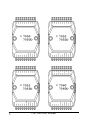
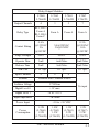
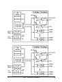
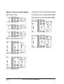
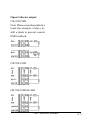
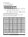
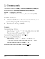
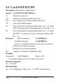
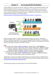
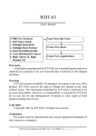
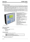
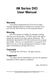
CB-7000 DIO User’s Manual CB-7041/7041D CB-7042/7042D CB-7043/7043D CB-7044/7044D CB-7050/7050D CB-7052/7052D CB-7053/7053D CB-7060/7060D CB-7063/7063D/A/AD/B/BD CB-7065/7065D/A/AD/B/BD CB-7066/7066D CB-7067/7067D Measurement Computing Corp. Copyright September, 2000. All rights are reserved. CB-7000 DIO Manual 1 Table of Contents 1. Introduction .....................................................4 1.1 More Information .......................................4 1.2 Pin Assignments.........................................5 1.3 Specifications .............................................9 1.4 Block Diagrams........................................13 1.5 Wire Connection.......................................21 1.6 Quick Start ...............................................24 1.7 Default Settings........................................24 1.8 Jumper Settings ........................................24 1.9 Configuration Tables ................................24 2. Command.......................................................26 2.1 %AANNTTCCFF.....................................28 2.2 #** ...........................................................29 2.3 #AABBDD ...............................................30 2.4 #AAN .......................................................33 2.5 $AA2 ........................................................34 2.6 $AA4 ........................................................35 2.7 $AA5 ........................................................36 2.8 $AA6 ........................................................37 2.9 $AAF ........................................................38 2.10 $AAM ....................................................39 2.11 $AAC .....................................................40 2.12 $AACN...................................................41 2 CB-7000 DIO Manual 2.13 $AALS ...................................................42 2.14 @AA ......................................................43 2.15 @AA(Data) ............................................44 2.16 ~AAO(Data)...........................................46 2.17 ~** .........................................................47 2.18 ~AA0 ......................................................48 2.19 ~AA1 ......................................................49 2.20 ~AA2 ......................................................50 2.21 ~AA3EVV..............................................51 2.22 ~AA4V ...................................................53 2.23 ~AA5V ...................................................55 3. Application Note............................................57 3.1 INIT* pin Operation .................................57 3.2 Module Status ..........................................57 3.3 Dual Watchdog Operation ........................58 3.4 Reset Status..............................................58 3.5 Digital Output ..........................................58 3.6 Latch Digital Input ...................................59 4 DN Module......................................................60 4.1 DN-SSR4 .................................................60 4.2 DN-PR4....................................................61 4.3 RM-104, RM-108, RM-116 .....................62 4.4 RM-204, RM-208, RM-216 .....................63 4.5 Application ...............................................64 CB COM Digital.p65 CB-7000 DIO Manual 3 1. Introduction CB-7000 is a family of network data acquisition and control modules. They provide analog-to-digital, digital-to-analog, digital input/output, timer/counters and other functions. These modules can be remotely controlled by a set of commands. The DIO modules support TTL signals, photo-isolated digital inputs, relay contact outputs, solid-state relay outputs, PhotoMOS outputs, and open-collector outputs. Refer to Sec. 1.3 for detailed information. 1.1 More Information 1.1 CB-7000 Overview 1.2 CB-7000 Pin Assignments 1.3 CB-7000 Specifications 1.4 CB-7000 Block Diagrams 1.5 CB-7000 Connections 4 CB-7000 DIO Manual 1.2 Pin Assignments CB-7000 DIO Manual 5 6 CB-7000 DIO Manual CB-7000 DIO Manual 7 8 CB-7000 DIO Manual 1.3 Specifications Digital Input Modules I- 7041/41D I- 7052/52D I- 7053/53D Input Channels 14 8 16 Isolation Isolation with Common Source 6 differential and 2 common ground Non- Isolated Isolation Voltage 3750 Vrms 5000 Vrms Non- Isolated Digital Level 0 +1V max +1V max +2V max Digital Level 1 +4 to +30 V +4 to +30 V +4 to +30 V Input Impedance 3K ohms 3K ohms 820 ohms Power Input +10 to +30 VDC Power Consumption 0.2W(I- 7041) 0.2W(I- 7052) 0.7W(I- 7053) 0.9W(I- 7041D) 0.6W(I- 7052D) 0.9W(I- 7053D) PhotoMOS Output Module I- 7066/66D Output Channels 7 Load Current 0.13A Load Voltage 350V max Isolation Voltage 5000VAC TurnOn Time 0.7mS typ TurnOff Time 0.05mS typ Power Input +10 to +30 VDC Power Consumption 0.5W(I- 7066) 0.8W(I- 7066D) CB-7000 DIO Manual 9 Open Collector Output Modules I- 7042 I- 7042D I- 7043 I- 7043D I- 7044 I- 7044D I- 7050 I- 7050D Output Channels 13 16 8 8 Isolation Isolation with Common Power Non- Isolation Isolation with Common Power Non- Isolation Isolation Voltage 3750 Vrms 3750 Vrms Load Voltage Max Load Current Max +30V 100mA 375mA 30mA Input Channels 4 7 Isolation Isolation with Common Source Non- Isolation No- Inputs Isolation Voltage 3750 Vrms Digital Level 0 1V max 1V max Digital Level 1 4 to 30V 3.5 to 30V Input Impedance 3K ohms Power Input Power Consumption 10 +10 to +30 VDC 1.0W (I- 7042) 1.7W (I- 7042D) 0.4W (I- 7043) 1.1W (I- 7043D) 1. 0 W (I- 7044) 1. 7 W (I- 7044D) CB-7000 DIO Manual 0.4W (I- 7050) 1.1W (I- 7050D) Relay Output Modules I- 7060 I- 7060D I- 7063 I- 7063D I- 7065 I- 7065D I- 7067 I- 7067D Output Channels 4 3 5 7 Relay Type RL1, RL2 : Form A RL3, RL4 : Form C Form A Form A Form A Contact Rating 0.6A @125VAC 2A @30VDC 5A@250VAC 5A@30VDC 0.5A @120VAC 1. 0 A @24VDC Surge Strength 500V 4000V 15 0 0 V Operate Time 3mS 6mS Max. 5mS Max. Release Time 2mS 3mS Max. 2mS Max. Min. Life 5*105 ops. 105 ops. 105 ops. Input Channels 4 8 4 Isolation Isolation with Common Source Isolation Voltage 3750Vrms Digital Level 0 +1V max Digital Level 1 +4 to +30 V Input Impedance 3K ohms Power Input Power Consumption No input +10 to +30 VDC 1.3W (I- 7060) 1.9W (I- 7060D) 1. 0 W (I- 7063) 1. 5 W (I- 7063D) 1. 3 W (I- 7065) 2.2W (I- 7065D) CB-7000 DIO Manual 1. 5 W (I- 7067) 2.2W (I- 7067D) 11 Solid- State Relay Output Modules Output Channels I- 7063A I- 7063AD I- 7065A I- 7065AD I- 7063B I- 7063BD I- 7065B I- 7065BD 3 5 3 5 SSR Type AC- SSR, Normal Open DC- SSR, Normal Open Load Voltage Range 24 to 265 Vrms 3 to 30 VDC Leakage Current 1.5 mArms 0.1 mA Max Load Current 1.0 Arms 1.0 A Min. Operate Time Min. Release Time 1mS 1/2 cycle + 1mS Dielectric Strength Input Channels 1mS 2500 Vrms 8 4 8 4 Isolation Isolation with Common Source Isolation Voltage 3750Vrms Digital Level 0 +1V max Digital Level 1 +4 to +30 V Input Impedance 3K ohms Power Input +10 to +30 VDC Power Consumption 0.7W 0.8W 0.6W 0.7W (I- 7063A) (I- 7065A) (I- 7063B) (I- 7065B) 1.5W 1.6W 1.4W 1.5W (I- 7063AD) (I- 7065AD) (I- 7063BD) (I- 7065BD) Note: Model numbers “I-nnnn” and model numbers “CB-nnnn” are identical. 12 CB-7000 DIO Manual 1.4 Block Diagrams CB-7000 DIO Manual 13 14 CB-7000 DIO Manual CB-7000 DIO Manual 15 16 CB-7000 DIO Manual CB-7000 DIO Manual 17 18 CB-7000 DIO Manual CB-7000 DIO Manual 19 20 CB-7000 DIO Manual 1.5 Connections Dry Contact signal input CB-7052/52D TTL/CMOS signal input CB-7052/52D CB-7050/50D/53/53D CB-7050/50D/53/53D CB-7041/41D/44/44D/60/60D/ CB-7041/41D/44/44D/60/60D/ 63/63D/63A/63AD/63B/63BD/ 63/63D/63A/63AD/63B/63BD/ 65/65D/65A/65AD/65B/65BD 65/65D/65A/65AD/65B/65BD CB-7000 DIO Manual 21 Open Collector signal input CB-7052/52D CB-7041/41D/44/44D/60/60D/ 63/63D/63A/63AD/63B/63BD/ 65/65D/65A/65AD/65B/65BD CB-7050/50D/53/53D 22 CB-7000 DIO Manual Open Collector output CB-7050/50D Note: When connecting inductive loads (for example, a relay), install a diode to prevent counter EMF kickback. CB-7043/43D CB-7042/42D/44/44D CB-7000 DIO Manual 23 1.6 Quick Start Refer to “CBCOM Series Network Setup and Quick Start Manual” and “Getting Started” for details. 1.7 Default Setting Default setting for CB-7000 DIO modules: l Address: 01 l Baud rate: 9600 bps l Type: Type 40 for DIO mode l Checksum Disable CB-7043/43D jumper setting at INIT* CB-7053/53D jumper setting at INIT* l l 1.8 Jumper Setting CB-7043/43D: Jumper J3 for select the pin INIT*/DO15 Select DO15 Select INIT* (default) CB-7053/53D: Jumper J1 for select the pin INIT*/DI15 Select DI15 Select INIT* (default) 1.9 Configuration Tables Configuration Table of CB-7000 DIO modules Baud rate Setting (CC) C ode 03 04 05 06 07 08 Baudrate 1200 2400 4800 9600 19 2 0 0 38400 24 CB-7000 DIO Manual 09 0A 57600 115200 Type Setting (TT) Type = 40 for DIO mode Data Format Setting (FF) 7 6 *1 *2 5 4 3 0 0 0 2 1 0 *3 *1: Counter Update Direction: 0=Falling Edge, 1=Rising Edge *2: Checksum Bit: 0=Disable, 1=Enable *3: 7050 = 0 (Bit[2.1.0] = 000), 7060 = 1 (Bit[2.1.0] = 001) 7052 = 2 (Bit[2.1.0] = 010), 7053 = 3 (Bit[2.1.0] = 011) Read Digital Input/Output Data Format Data of $AA6,$AA4,$AALS: (First Data)(Second Data)00 Data of @AA: (First Data)(Second Data) First Data Second Data I- 7041/41D DI(8- 13) 00 to 3F DI(0- 7) 00 to FF I- 7042/42D DO(8- 12) 00 to 1F DO(0- 7) 00 to FF I- 7043/43D DO(8- 15) 00 to FF DO(0- 7) 00 to FF I- 7044/44D DO(1- 8) 00 to FF DI(1- 4) 00 to 0F I- 7050/50D DO(0- 7) 00 to FF DI(0- 6) 00 to 7F I- 7052/52D DI(0- 7) 00 to FF 00 00 I- 7053/53D DI(8- 15) 00 to FF DI(0- 7) 00 to FF I- 7060/60D DO(1- 4) 00 to 0F DI(1- 4) 00 to 0F I- 7063s *1 DO(1- 3) 00 to 07 DI(1- 8) 00 to FF I- 7065s *2 DO(1- 5) 00 to 1F DI(1- 4) 00 to 0F I- 7066/66D DO(1- 7) 00 to 7F 00 00 I- 7067/67D DO(1- 7) 00 to 7F 00 00 *1 I- 7063s include : I- 7063/63D/63A/63AD/63B/63BD *2 I- 7065s include : I- 7065/65D/65A/65AD/65B/65BD CB-7000 DIO Manual 25 2. Commands Command Format: (Leading)(Address)(Command)[CHK](cr) Response Format: (Leading)(Address)(Data)[CHK](cr) [CHK] 2-character checksum (cr) end-of-Command character, character return(0x0D) Calculate Checksum: 1. Calculate ASCII sum of all characters of command (or response) string except the carriage return (cr). 2. Mask the sum of string with 0ffh. Example: Command string: $012(cr) Sum of string = ‘$’+‘0’+‘1’+‘2’ = 24h+30h+31h+32h = B7h The checksum is B7h, and [CHK] = “B7” Command string with checksum: $012B7(cr) Response string: !01400600(cr) Sum of string: ‘!’+‘0’+‘1’+‘4’+‘0’+‘0’+‘6’+‘0’+‘0’ = 21h+30h+31h+34h+30h+30h+36h+30h+30h = 1ACh The checksum is ACh, and [CHK] = “AC” Response string with checksum: !01400600AC(cr) 26 CB-7000 DIO Manual Ge ne ral Command Se ts Command R e s pons e D e s cription Se ction %AAN N TTCCFF !AA Set Module Configuration Sec.2.1 #** N o Response Synchronized Sampling Sec.2.2 #AABBDD > Digital O uput Sec.2.3 #AAN !AA(Data) Read Digital Input Counter Sec.2.4 $AA2 !AATTCCFF Read Configuration Sec.2.5 $AA4 !S(Data) Read Synchronized Data Sec.2.6 $AA5 !AAS Read Reset Status Sec.2.7 $AA6 !(Data) Read Digital I/O Status Sec.2.8 $AAF !AA(Data) Read Firmware Version Sec.2.9 $AAM !AA(Data) Read Module N ame Sec.2.10 $AAC !AA Clear Latched Digital Input Sec.2.11 $AACN !AA Clear Ditial Input Count $AALS !(Data) Read Latched Digital Input Sec.2.13 @AA >(Data) Read Digital Input Sec.2.14 @AA(Data) > Set Digital O utput Sec.2.15 ~AAO (Data) !AA Set Module N ame Sec.2.16 Sec.2.12 Hos t Watchdog Command Se ts Command R e s pons e D e s cription Se ction ~ ** N o Response Host O K Sec.2.17 ~AA0 !AASS Read Module Status Sec.2.18 ~AA1 !AA Reset Module Status Sec.2.19 ~AA2 !AAVV Read Host Watchdog Timeout Value Sec.2.20 ~AA3EVV !AA Set Host Watchdog Timeout Value Sec.2.21 ~AA4V !AA(Data) Read PowerO n/Safe Value Sec.2.22 ~AA5V !AA Set PowerO n/Safe Value CB-7000 DIO Manual Sec.2.23 27 2.1 %AANNTTCCFF Description: Set module Configuration Syntax: %AANNTTCCFF[CHK](cr) % Delimiter character AA Address of setting module (00 to FF) NN New Address for setting module (00 to FF) TT Type 40 for DIO module CC New baud rate for setting module (Ref. Sec. 1.9). Short INIT* to ground when changing baud rate. (Ref Sec. 3.1) FF New data format for setting module (Ref. Sec. 1.9). Short the INIT* to ground to change checksum setting. (Ref. Sec. 3.1) Response: Valid Command: !AA[CHK](cr) Invalid Command: ?AA[CHK](cr) Syntax or communication error may get no response. ! Delimiter for valid Command ? Delimiter for invalid Command AA Address of response module(00 to FF) Example: Command: %0102400600 Receive: !02 Set module Address 01 to 02; return successful. Related Command: Sec. 2.5 $AA2 Related Topics: Sec. 1.9 Configuration Tables, Sec. 3.1 INIT* pin Operation 28 CB-7000 DIO Manual 2.2 #** Description: Synchronized Sampling Syntax: #**[CHK](cr) # Delimiter character ** Synchronized sampling Command Response: No response Example: Command: #** No response Send synchronized sampling Command to all modules. Command: $014 Receive: !10F0000 Read synchronized data from Address 01, return S=1, first read and data. Command: $014 Receive: !00F0000 Read synchronized data from Address 02, return S=0, have read data. Related Command: Sec. 2.6 $AA4 CB-7000 DIO Manual 29 2.3 #AABBDD Description: Digital Output Command: #AABBDD[CHK](cr) # Delimiter character AA Address of reading module(00 to FF) BBDD Output command and parameter For multichannel outputs, set BB = 00, 0A, or 0B. It selects the output group. DD is the output value. Parameter for Multi- Channel Output Output Channels DD for command #AABBDD BB=00/0A BB=0B I- 7042/42D 13 00 to FF DO(0- 7) 00 to 1F DO(8- 12) I- 7043/43D 16 00 to FF DO(0- 7) 00 to FF DO(8- 15) I- 7044/44D 8 00 to FF DO(1- 8) NA NA I- 7050/50D 8 00 to FF DO(0- 7) NA NA I- 7060/60D 4 00 to 0F RL(1- 4) NA NA I- 7063s *1 3 00 to 07 RL(1- 3) NA NA I- 7065s *2 5 00 to 1F RL(1- 5) NA NA I- 7066/66D 7 00 to 7F RL(1- 7) NA NA I- 7067/67D 7 00 to 7F RL(1- 7) NA NA *1 *2 I- 7063s include : I- 7063/63D/63A/63AD/63B/63BD I- 7065s include : I- 7065/65D/65A/65AD/65B/65BD To output a single-channel, set BB = 1c, Ac, or Bc where c is the selected channel. Set DD to 00 to clear output and 01 to set the output. 30 CB-7000 DIO Manual Parameter for Single- Channel Output Single channel output command #AABBDD c for BB=1c/Ac c for BB=Bc I- 7042/42D 0 to 7 DO(0- 7) 0 to 4 DO(8- 12) I- 7043/43D 0 to 7 DO(0- 7) 0 to 7 DO(8- 15) I- 7044/44D 0 to 7 DO(1- 8) NA NA I- 7050/50D 0 to 7 DO(0- 7) NA NA I- 7060/60D 0 to 3 RL(1- 4) NA NA I- 7063s *1 0 to 2 RL(1- 3) NA NA I- 7065s *2 0 to 4 RL(1- 5) NA NA I- 7066/66D 0 to 6 RL(1- 7) NA NA I- 7067/67D 0 to 6 RL(1- 7) NA NA *1 *2 I- 7063s include : I- 7063/63D/63A/63AD/63B/63BD I- 7065s include : I- 7065/65D/65A/65AD/65B/65BD Response: Valid Command: >[CHK](cr) Invalid Command: ?[CHK](cr) Ignored Command:  Syntax or communication error may get no response. > Delimiter for valid Command ? Delimiter for invalid Command ! Delimiter for ignoring the Command. The module’s host watchdog timeout status is set, and the output is set to Safe Value. Example: Command: #0100FF Receive: > Assume module is CB-7044, set Address 01 output value FF; return is successful. Command: #021001 Receive: > CB-7000 DIO Manual 31 Assume module is CB-7067, set Address 02 channel 0 on, return is successful. Command: #021701 Receive: ? Set Address 02 channel 7 on, return the channel is invalid for CB-7067; it only has seven outputs (0 to 6). Command: #0300FF Receive: ! Set Address 03 output value FF, return ignore. The module’s host watchdog timeout status is set, and the output is set to Safe Value. Related Command: Sec. 2.15 @AA(Data), Sec. 2.18 ~AA0, Sec. 2.19 ~AA1 Related Topics: Sec. 1.9 Configuration Tables, Sec. 3.2 Module Status, Sec. 3.3 Dual Watchdog Operation Note: The Command is not for CB-7041/41D/52/52D/53/53D. 32 CB-7000 DIO Manual 2.4 #AAN Description: Read Digital Input Counter from channel N Command: #AAN[CHK](cr) # Delimiter character AA Address of reading module (00 to FF) N channel to read Response: Valid Command: !AA(Data)[CHK](cr) Invalid Command: ?AA[CHK](cr) Syntax or communication error may get no response. ! Delimiter for valid Command ? Delimiter for invalid Command AA Address of response module(00 to FF) (Data) Digital input counter value in decimal, from 00000 to 65535 Example: Command: #032 Receive: !0300103 Read Address 03 digital input counter value of channel 2, return value 103. Command: #025 Receive: ?02 Read Address 02 digital input counter value of channel 5, return the channel is not available. Related Command: Sec. 2.12 $AACN Note: The Command is not for CB-7042/42D/43/43D/66/66D/67/67D. CB-7000 DIO Manual 33 2.5 $AA2 Description: Read Configuration Command: $AA2[CHK](cr) $ Delimiter character AA Address of reading module (00 to FF) 2 Command for read configuration Response: Valid Command: !AATTCCFF[CHK](cr) Invalid Command: ?AA[CHK](cr) Syntax or communication error may get no response. ! Delimiter for valid Command ? Delimiter for invalid Command AA Address of response module(00 to FF) TT Type code of module; it must be 40 CC Baud rate code of module (Ref. Sec. 1.9) FF Data format of module (Ref. Sec. 1.9) Example: Command: $012 Receive: !01400600 Read Address 01 status, return DIO mode, baud 9600, no checksum. Related Command: Sec. 2.1, %AANNTTCCFF Related Topics: Sec. 1.9, Configuration Tables; Sec. 3.1, INIT* pin Operation 34 CB-7000 DIO Manual 2.6 $AA4 Description: Read Synchronized Data Command: $AA4[CHK](cr) $ Delimiter character AA Address of reading module (00 to FF) 4 Command for read synchronized data Response: Valid Command: !S(Data)[CHK](cr) Invalid Command: ?AA[CHK](cr) Syntax or communication error may get no response. ! Delimiter for valid Command ? Delimiter for invalid Command AA Address of response module(00 to FF) S Status of synchronized data, 1 = first read, 0 = been read (Data) synchronized DIO value (Ref. Sec. 1.9) Example: Command: $014 Receive: ?01 Read Address 01 synchronized data, return no data available. Command: #** Receive: no response Send synchronized sampling to all modules. Command: $014 Receive: !1000F00 Read Address 01 synchronized data, return S=1, first read, and synchronized data 0F00 Related Command: Sec. 2.2, #** Related Topics: Sec. 1.9, Configuration Tables CB-7000 DIO Manual 35 2.7 $AA5 Description: Read Reset Status Command: $AA5[CHK](cr) $ Delimiter character AA Address of reading module (00 to FF) 5 Command for read reset status Response: Valid Command: !AAS[CHK](cr) Invalid Command: ?AA[CHK](cr) Syntax or communication error may get no response. ! Delimiter for valid Command ? Delimiter for invalid Command AA Address of response module(00 to FF) S Reset status, 1 = the module has been reset, 0 = the module has not been reset. Example: Command: $015 Receive: !011 Read Address 01 reset status, return first read. Command: $015 Receive: !010 Read Address 01 reset status, return no reset occurred. Related Topics: Sec3.4, Reset Status 36 CB-7000 DIO Manual 2.8 $AA6 Description: Read Digital I/O Status Command: $AA6[CHK](cr) $ Delimiter character AA Address of reading module (00 to FF) 6 Command for read digital input/output status Response: Valid Command: !(Data)[CHK](cr) Invalid Command: ?AA[CHK](cr) Syntax or communication error may get no response. ! Delimiter for valid Command ? Delimiter for invalid Command AA Address of response module(00 to FF) (Data) Digital input/output value (Ref. Sec. 1.9) Example: Command: $016 Receive: !0F0000 Assume module is CB-7060. Read Address 01 DIO status, return 0F00; digital input IN1 to IN4 are open, digital output RL1 to RL4 are off. Related Command: Sec. 2.14, @AA Related Topics: Sec. 1.9, Configuration Tables CB-7000 DIO Manual 37 2.9 $AAF Description: Read Firmware Version Command: $AAF[CHK](cr) $ Delimiter character AA Address of reading module (00 to FF) F Command for read firmware version Response: Valid Command: !AA(Data)[CHK](cr) Invalid Command: ?AA[CHK](cr) Syntax or communication error may get no response. ! Delimiter for valid Command ? Delimiter for invalid Command AA Address of response module(00 to FF) (Data) Firmware version of module Example: Command: $01F Receive: !01A2.0 Read Address 01 firmware version, return version A2.0. Command: $02F Receive: !01B1.1 Read Address 01 firmware version, return version B1.1. 38 CB-7000 DIO Manual 2.10 $AAM Description: Read Module Name Command: $AAM[CHK](cr) $ Delimiter character AA Address of reading module (00 to FF) M Command for read module name Response: Valid Command: !AA(Data)[CHK](cr) Invalid Command: ?AA[CHK](cr) Syntax or communication error may get no response. ! Delimiter for valid Command ? Delimiter for invalid Command AA Address of response module(00 to FF) (Data) Name of module Example: Command: $01M Receive: !017042 Read Address 01 module name, return name 7042. Command: $03M Receive: !037060D Read Address 03 module name, return name 7060D. Related Command: Sec. 2.16, ~AAO(Data) CB-7000 DIO Manual 39 2.11 $AAC Description: Clear Latched Digital Input Command: $AAC[CHK](cr) $ Delimiter character AA Address of setting module (00 to FF) C Command for clear latched digital input Response: Valid Command: !AA[CHK](cr) Invalid Command: ?AA[CHK](cr) Syntax or communication error may get no response. ! Delimiter for valid Command ? Delimiter for invalid Command AA Address of response module(00 to FF) Example: Command: $01L0 Receive: !01FFFF00 Read Address 01 latch-low data, return FFFF. Command: $01C Receive: !01 Clear Address 01 latched data, return successful. Command: $01L0 Receive: !01000000 Read Address 01 latch-low data, return 0000. Related Command: Sec. 2.13, $AALS Note: The Command is not for CB-7042/42D/43/43D/66/66D/67/67D. 40 CB-7000 DIO Manual 2.12 $AACN Description: Clear Digital Input Counter Command: $AACN[CHK](cr) $ Delimiter character AA Address of setting module (00 to FF) C Command for clear digital input counter N Digital counter channel N to clear Response: Valid Command: !AA[CHK](cr) Invalid Command: ?AA[CHK](cr) Syntax or communication error may get no response. ! Delimiter for valid Command ? Delimiter for invalid Command AA Address of response module(00 to FF) Example: Command: #010 Receive: !0100123 Read Address 01 input channel 0 counter value, return 123. Command: $01C0 Receive: !01 Clear Address 01 input channel 0 counter value, return successful. Command: #010 Receive: !0100000 Read Address 01 input channel 0 counter value, return 0. Related Command: Sec. 2.4, #AAN Note: The Command is not for CB-7042/42D/43/43D/66/66D/67/67D. CB-7000 DIO Manual 41 2.13 $AALS Description: Read Latched Digital Input Command: $AALS[CHK](cr) $ Delimiter character AA Address of reading module (00 to FF) L Command for reading latched digital input S 1 = select latched high status, 0 = select latched low Response: Valid Command: !(Data)[CHK](cr) Invalid Command: ?AA[CHK](cr) Syntax or communication error may get no response. ! Delimiter for valid Command ? Delimiter for invalid Command AA Address of response module(00 to FF) (Data) read status (Ref. Sec. 1.9) 1= the input channel is latched, 0=the input channel is not latched. Example: Command: $01L1 Receive: !012300 Read Address 01 latch-high data, return 0123. Command: $01C Receive: !01 Clear Address 01 latched data, return successful. Command: $01L1 Receive: !000000 Read Address 01 latch-high data, return 0. Related Command: Sec. 2.11, $AAC Note: The Command is not for CB-7042/42D/43/43D/66/66D/67/67D. 42 CB-7000 DIO Manual 2.14 @AA Description: Read Digital Input/Output Status Command: @AA[CHK](cr) @ Delimiter character AA Address of reading module (00 to FF) Response: Valid Command: >(Data)[CHK](cr) Invalid Command: ?AA[CHK](cr) Syntax or communication error may get no response. > Delimiter for valid Command ? Delimiter for invalid Command AA Address of response module(00 to FF) (Data) Read DIO status (Ref. Sec. 1.9) Example: Command: @01 Receive: >0F00 Read Address 01 DIO status, return 0F00. Related Command: Sec. 2.8, $AA6 Related Topics: Sec. 1.9, Configuration Tables CB-7000 DIO Manual 43 2.15 @AA(Data) Description: Set Digital Output Command: @AA(Data)[CHK](cr) @ Delimiter character AA Address of setting module (00 to FF) (Data) output value, the data format is following: (Data) is one character for output channel less than 4 For CB-7060/60D, from 0 to F For CB-7063/63D/63A/63AD/63B/63BD, from 0 to 7 (Data) is two characters for output channel less than 8 For CB-7044/44D/50/50D, from 00 to FF For CB-7065/65D/65A/65AD/65B/65BD, from 00 to 1F For CB-7066/66D/67/67D, from 00 to 7F (Data) is four characters for output channel less than 16 For CB-7042/42D, from 0000 to 1FFF For CB-7043/43D, from 0000 to FFFF Response: Valid Command: >[CHK](cr) Invalid Command: ?[CHK](cr) Ignore Command:  Syntax or communication error may get no response. > Delimiter for valid Command. ? Delimiter for invalid Command. ! Delimiter for ignore Command. The module is in Host Watchdog Timeout Mode, and the output is set to SafeValue. Example: Command: @017 Receive: > 44 CB-7000 DIO Manual Output Address 02 value 7, return successful.(The example is suitable for CB-7060/60D/63/63D/63A/63AD/63B/63BD) Command: @0200 Receive: > Output Address 01 value 00, return successful.(The example is suitable for CB-7044/44D/50/50D/65/65D/65A/65AD/65B/ 65BD/66/66D/67/67D) Command: @030012 Receive: ! Output Address 03 value 0012, return the module is in host watchdog timeout mode, the output Command is ignored. (The example is suitable for CB-7042/42D/43/43D) Related Command: Sec. 2.3, #AABBDD; Sec. 2.18, ~AA0; Sec. 2.19, ~AA1 Relate;d Topics: Sec. 1.9, Configuration Tables; Set.3.2, Module Status; Sec. 3.3 Dual Watchdog Operation; Sec. 3.5, Digital Output Note: The Command is not for CB-7041/41D/52/52D/53/53D. CB-7000 DIO Manual 45 2.16 ~AAO(Data) Description: Set Module Name Command: ~AAO(Data)[CHK](cr) ~ Delimiter character AA Address of setting module (00 to FF) O Command for set module name (Data) New name for module, max 6 characters Response: Valid Command: !AA[CHK](cr) Invalid Command: ?AA[CHK](cr) Syntax or communication error may get no response. ! Delimiter for valid Command ? Delimiter for invalid Command AA Address of response module(00 to FF) Example: Command: ~01O7050 Receive: !01 Set Address 01 module name 7050, return successful. Command: $01M Receive: !017050 Read Address 01 module name, return name 7050. Related Command: Sec. 2.10, $AAM 46 CB-7000 DIO Manual 2.17 ~** Description: Host OK. Host send this Command to all modules for send the information “Host OK”. Command: ~**[CHK](cr) ~ Delimiter character ** Command for all modules Response: No response. Example: Command: ~** No response Related Command: Sec. 2.18, ~AA0; Sec. 2.19, ~AA1; Sec. 2.20, ~AA2; Sec. 2.21, ~AA3EVV; Sec. 2.22, ~AA4V; Sec. 2.23, ~AA5V Related Topic: Sec. 3.2, Module Status; Sec. 3.3, Dual Watchdog Operation CB-7000 DIO Manual 47 2.18 ~AA0 Description: Read Module Status Command: ~AA0[CHK](cr) ~ Delimiter character AA Address of reading module (00 to FF) 0 Command for read module status Response: Valid Command: !AASS[CHK](cr) Invalid Command: ?AA[CHK](cr) Syntax or communication error may get no response. ! Delimiter for valid Command ? Delimiter for invalid Command AA Address of response module(00 to FF) SS Module status, 00=host watchdog timeout status is clear, 04=host watchdog timeout status is set. The status will store into EEPROM and only may reset by the Command ~AA1. Example: Refer to Sec. 2.21, ~AA3EVV example. Related Command: Sec. 2.17, ~**; Sec. 2.19, ~AA1; Sec. 2.20, ~AA2; Sec. 2.21, ~AA3EVV; Sec. 2.22, ~AA4V; Sec. 2.23, ~AA5V Related Topic: Sec. 3.2, Module Status; Sec. 3.3, Dual Watchdog Operation 48 CB-7000 DIO Manual 2.19 ~AA1 Description: Reset Module Status Command: ~AA1[CHK](cr) ~ Delimiter character AA Address of setting module (00 to FF) 1 Command for reset module status Response: Valid Command: !AA[CHK](cr) Invalid Command: ?AA[CHK](cr) Syntax or communication error may get no response. ! Delimiter for valid Command ? Delimiter for invalid Command AA Address of response module (00 to FF) Example: Refer to Sec. 2.21, ~AA3EVV example. Related Command: Sec. 2.17, ~**; Sec. 2.18, ~AA0; Sec. 2.20, ~AA2; Sec. 2.21, ~AA3EVV; Sec. 2.22, ~AA4V; Sec. 2.23, ~AA5V Related Topic: Sec. 3.2, Module Status; Sec. 3.3, Dual Watchdog Operation CB-7000 DIO Manual 49 2.20 ~AA2 Description: Read Host Watchdog Timeout Value Command: ~AA2[CHK](cr) ~ Delimiter character AA Address of reading module (00 to FF) 2 Command for read host watchdog timeout value Response: Valid Command: !AAEVV[CHK](cr) Invalid Command: ?AA[CHK](cr) Syntax or communication error may get no response. ! Delimiter for valid Command ? Delimiter for invalid Command AA Address of response module(00 to FF) E Host watchdog enable status, 1 = Enable, 0 = Disable VV Timeout value in HEX format, each count is 0.1 second, 01h = 0.1 second and FFh = 25.5 seconds Example: Refer to Sec. 2.21, ~AA3EVV example. Related Command: Sec. 2.17, ~**; Sec. 2.18, ~AA0; Sec. 2.19, ~AA1; Sec. 2.21, ~AA3EVV; Sec. 2.22, ~AA4V; Sec. 2.23, ~AA5V Related Topic: Sec. 3.2, Module Status; Sec. 3.3, Dual Watchdog Operation 50 CB-7000 DIO Manual 2.21 ~AA3EVV Description: Set Host Watchdog Timeout Value Command: ~AA3EVV[CHK](cr) ~ Delimiter character AA Address of setting module (00 to FF) 3 Command for set host watchdog timeout value E 1 = Enable, 0 = Disable host watchdog VV Timeout value, from 01 to FF, each for 0.1 second Response: Valid Command: !AA[CHK](cr) Invalid Command: ?AA[CHK](cr) Syntax or communication error may get no response. ! Delimiter for valid Command ? Delimiter for invalid Command AA Address of response module (00 to FF) Example: Command: ~010 Receive: !0100 Read Address 01 module status, return host watchdog timeout status is clear. Command: ~013164 Receive: !01 Set Address 01 host watchdog timeout value 10.0 seconds and enable host watchdog, return successful. Command: ~012 Receive: !01164 Read Address 01 host watchdog timeout value; return that host watchdog is enabled, and time interval is 10.0 seconds. Command: ~** No response CB-7000 DIO Manual 51 Reset the host watchdog timer. Wait for about 10 seconds and don’t send command ~**, the LED of module will flash. The flashing LED indicates the host watchdog timeout status is set. Command: ~010 Receive: !0104 Read Address 01 modul status, return host watchdog timeout status is set. Command: ~012 Receive: !01064 Read Address 01 host watchdog timeout value, return that host watchdog is disabled, and time interval is 10.0 seconds. Command: ~011 Receive: !01 Reset Address 01 host watchdog timeout status, return successful. And the LED of this module stop flash. Command: ~010 Receive: !0100 Read Address 01 module status, return host watchdog timeout status is clear. Related Command: Sec. 2.17, ~**; Sec. 2.18, ~AA0; Sec. 2.19, ~AA1; Sec. 2.20, AA2; Sec. 2.22, ~AA4V; Sec. 2.23, ~AA5V Related Topic: Sec. 3.2, Module Status; Sec. 3.3, Dual Watchdog Operation 52 CB-7000 DIO Manual 2.22 ~AA4V Description: Read PowerOn/Safe Value. Command: ~AA4V[CHK](cr) ~ Delimiter character AA Address of reading module (00 to FF) 4 Command for read PowerOn/Safe Value V P = read PowerOn value, S = read Safe Value Response: Valid Command: !AA(Data)[CHK](cr) Invalid Command: ?AA[CHK](cr) Syntax or communication error may get no response. ! Delimiter for valid Command ? Delimiter for invalid Command AA Address of response module(00 to FF) (Data) PowerOn Value or Safe Value For CB-7042/42D/43/43D (Data) is VVVV, where VVVV is the PowerOn Value (or Safe Value). For other modules, (Data) is VV00, where VV is the PowerOn Value(or Safe Value). Example: Command: @010000 Receive: > Output Address 01 value 0000, return successful. Command: ~015S Receive: !01 Set Address 01 Safe Value, return successful. Command: @01FFFF Receive: > Output Address 01 value FFFF, return successful. Command: ~015P Receive: !01 CB-7000 DIO Manual 53 Set Address 01 PowerOn Value, return successful. Command: ~014S Receive: !010000 Read Address 01 Safe Value, return 0000. Command: ~014P Receive: !01FFFF Read Address 01 PowerOn Value, return FFFF. Related Command: Sec. 2.17, ~**; Sec. 2.18, ~AA0; Sec. 2.19, ~AA1; Sec. 2.20, ~AA2; Sec. 2.21, ~AA3EVV; Sec. 2.23, ~AA5V Related Topic: Sec. 3.2, Module Status; Sec. 3.3, Dual Watchdog Operation Note: The Command is not for CB-7041/41D/52/52D/53/53D. 54 CB-7000 DIO Manual 2.23 ~AA5V Description: Set PowerOn/Safe Value. Command: ~AA5V[CHK](cr) ~ Delimiter character AA Address of setting module (00 to FF) 5 Command for set PowerOn/Safe Value V P = set current output as PowerOn Value, S = set current output as Safe Value Response: Valid Command: !AA[CHK](cr) Invalid Command: ?AA[CHK](cr) Syntax or communication error may get no response. ! Delimiter for valid Command ? Delimiter for invalid Command AA Address of response module(00 to FF) Example: Command: @01AA Receive: > Output Address 01 value AA, return successful. Command: ~015P Receive: !01 Set Address 01 PowerOn Value, return successful. Command: @0155 Receive: > Output Address 01 value 55, return successful. Command: ~015S Receive: !01 Set Address 01 Safe Value, return successful. Command: ~014P Receive: !01AA00 Read Address 01 PowerOn Value, return PowerOn Value AA. Command: ~014S Receive: !015500 CB-7000 DIO Manual 55 Read Address 01 Safe Value, return Safe Value 55. Related Command: Sec. 2.17, ~**; Sec. 2.18, ~AA0; Sec. 2.19, ~AA1; Sec. 2.20, ~AA2; Sec. 2.21, ~AA3EVV; Sec. 2.22, ~AA4V Related Topic: Sec. 3.2, Module Status; Sec. 3.3, Dual Watchdog Operation Note: The Command is not for CB-7041/41D/52/52D/53/53D. 56 CB-7000 DIO Manual 3. Application Notes 3.1 INIT* pin Operation Each CB-7000 module has a build-in EEPROM to store configuration information such as address, type, baud rate and other information. Sometimes, a user may forget the configuration of the module. Therefore, the CB-7000 have a special mode named “INIT mode”, to help user to resolve the problem. The “INIT mode” is setting as Address=00, baud rate=9600bps, no checksum To enable INIT mode, please follow these steps: Step 1. Power-down the module. Step 2. Connect the INIT* pin to the GND pin. Step 3. Power-up the module. Step 4. Send Command $002(cr) in 9600 bps to read the configuration stored in the module’s EEPROM. Refer to “7000 Bus Converter User Manual” Sec. 5.1 and “Getting Started” for more information. 3.2 Module Status PowerOn Reset or Module Watchdog Reset will set all outputs to the PowerOn Value. The module can accept the host’s Command to change the output value. Host Watchdog Timeout will set all output to the Safe Value.The module’s status (read by Command ~AA0) will be 04, and the output Command will be ignored. CB-7000 DIO Manual 57 3.3 Dual Watchdog Operation Dual Watchdog = Module Watchdog + Host Watchdog The Module Watchdog is a hardware reset circuit that monitors the module’s operating status. When working in harsh or noisy environment, the module may go down by a noise signal. The Module Watchdog times out and sets output to PowerOn value. The Host Watchdog is a software function to monitor the host’s operating status. Its purpose is to detect a network communication problem or a halted host. When the timeout interval expired, the module will put all outputs to the predefined Safe Value. This places the controlled element in a known-safe condition. The CB-7000 module with Dual Watchdog makes the control system more reliable and stable. 3.4 Reset Status The Reset Status is set while the module power on or reset by Module Watchdog, and is cleared when the Command read Reset Status ($AA5) is applied. This is useful for user to check the module’s working status. When the Reset Status is set means the module is reset and the output may be changed to the PowerOn Value. When the Reset Status is clear means the module is not reset, and the output cannot be changed. 3.5 Digital Output A module’s output can have one of three values: 1. Safe Value. If the host watchdog timeout status is set, the output is set to Safe Value.If the module receives an output CB-7000 DIO Manual 58 Command, such as @AA(Data) or #AABBDD, the module ignores the command and returns ‘!’, and will not change the output to the output command value. The host watchdog timeout status is set and stored in EEPROM when the host watchdog timeout interval expired, and only can be cleared by Command ~AA1. If user wants to change the output, he first needs to clear the host watchdog timeout status, then send an output command to change the output to a desired value. 2. PowerOn Value. When the Module Watchdog Timer is set, and the host watchdog timeout status is clear, the module’s output is set to the predefined PowerOn Value. 3. Output Command value. If the host watchdog timeout status is clear, the user issues a digital output command such as @AA(Data) or #AABBDD to the module for changing the output value. The module will respond successful (receive >). 3.6 Latched Digital Inputs If, for example, the user connects a PB switch to a a digital I/O module input channel and wants to read the switch stoke. The input is a pulse digial input, and user will lose the data. When read by Command $AA6 in A or B position, the response is that no input occurred and he will lose the pulse information. However, the read latch-low digital input Command $AAL0 will solve this problem. When $AAL0 Command in A and B position is issued, the response indicates that there was a low pulse between A and B position for a switch closure. CB-7000 DIO Manual 59 4 DN Module 4.1 DN-SSR4 Output Channel: Four Solid State Relay Contacts Output Specification: Type: Zero-Cross AC Solid-State Relay Output Rated Load Voltage: 200 to 240 VAC Rated Load Current: 4 Amps Surge Current: 50 A, Max. Off-State Leakage Current: 5.0 mA Operate Time: 1/2 cycle of voltage sine wave + 1ms Input Impedance: 1.5K Ohms DIN-Rail mounted Power Input: +24VDC 60 CB-7000 DIO Manual 4.2 DN-PR4 Output Channel: Four Mechanical Relay Contacts Output Specification: Type: 1 form-C Relay Contact Nominal Load: 5A@250VAC, 5A@30VDC Max. Switching Power: 1250VAC Max. Switching Voltage: 250VAC, 150VDC Max. Switching Current: 5 A. Mechanical/Electrical Life: Min. 10x106/10x104 operations. Operate/Release Time: Max. 10 ms/5 ms Dielectric Strength: 2000VAC 1 minute Nominal Coil Power: 360 mW DIN-Rail mounted Power Input: 24VDC CB-7000 DIO Manual 61 4.3 RM-104, RM-108, RM-116 Output Channel: 4/8/16 Relay Contacts Output Specification: Type: 1 Form-C Relay Contact Rated Load: 16 A.@250VAC Max. Switching Voltage: 400VAC Max. Peak Current: 30 A. Standard Contact Material: AgCd0 Min. Life: 100,000 operations. Din-Rail mounted Dimension: RM-104: 78 x 77mm RM-108: 135 x 77mm RM-116: 270 x 77mm Power Input: 24VDC 62 CB-7000 DIO Manual 4.4 RM-204, RM-208, RM-216 Output Channel: 4/8/16 Relay Contacts Relay Specification: Type: 2 Form-C Rated Load: 5 A.@250VAC Max. Switching Voltage: 400VAC Max. Peak Current: 10 A. Standard Contact Material: Ag Nt Min. Life: 100,000 operations. Din-Rail mounted Dimension: RM-204: 78 x 77mm RM-208: 135 x 77mm RM-216: 270 x 77mm Power Input: 24VDC CB-7000 DIO Manual 63 4.5 Application The DN Modules are the IO extension of CB-7000 modules. These modules can drive more power and heavy loads . User may use CB-7000 modules, like CB-7043 or others, to control the DN modules to drive loads. 64 CB-7000 DIO Manual For your notes. CB-7000 DIO Manual 65 For your notes. 66 CB-7000 DIO Manual EC Declaration of Conformity We, Measurement Computing Corp., declare under sole responsibility that the product: CB-7041/42/43/44/50/52/ 53/60/63/65/66/67 Part Number Digital I/O Modules Description to which this declaration relates, meets the essential requirements, is in conformity with, and CE marking has been applied according to the relevant EC Directives listed below using the relevant section of the following EC standards and other normative documents: EU EMC Directive 89/336/EEC: Essential requirements relating to electromagnetic compatibility. EU 55022 Class B: Limits and methods of measurements of radio interference characteristics of information technology equipment. EN 50082-1: EC generic immunity requirements. IEC 801-2: Electrostatic discharge requirements for industrial process measurement and control equipment. IEC 801-3: Radiated electromagnetic field requirements for industrial process measurements and control equipment. IEC 801-4: Electrically fast transients for industrial process measurement and control equipment. Carl Haapaoja, Director of Quality Assurance CB-7000 DIO Manual 67 Measurement Computing Corporation 10 Commerce Way Suite 1008 Norton, Massachusetts 02766 (508) 946-5100 Fax: (508) 946-9500 E-mail: [email protected] www.mccdaq.com