1
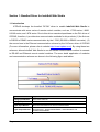
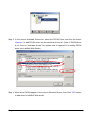
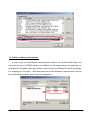
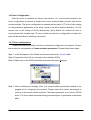
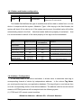
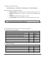
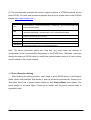
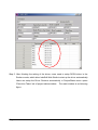
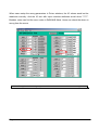
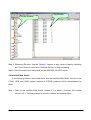
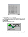
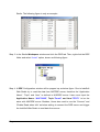
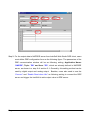
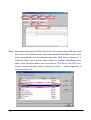
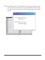
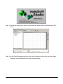
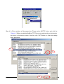
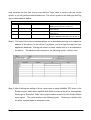
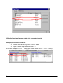
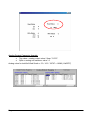
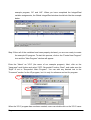
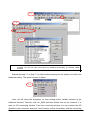
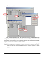
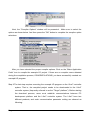
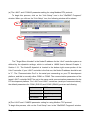
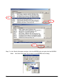
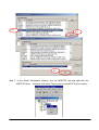
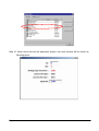
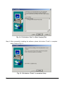
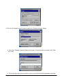
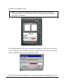
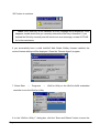
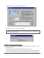
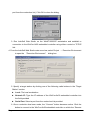
Manual for InduSoft Web Studio Solution
(version 1.02)
Produced by ICPDAS LTD., Co.
Page 1
Index
ICPDAS solution for InduSoft Web Studio ........................................................................................4
Section 1: Bundled Driver for InduSoft Web Studio..........................................................................7
1-2 General Characteristics...........................................................................................................9
1-2-1 Device Characteristics........................................................................................................9
1-2-2 Link Characteristics............................................................................................................9
1-2-3 Driver Characteristics.........................................................................................................9
1-2-4 Information about conformance testing ...........................................................................10
1-3 Installation the driver............................................................................................................10
1-3-1 Install DCON Driver into InduSoft Web Studio .............................................................. 11
1-3-2 Other software requirements ............................................................................................13
1-4 Driver Configuration.............................................................................................................14
1-4-1 Driver configuration .........................................................................................................14
1-4-2 Driver Worksheet..............................................................................................................16
1-4-3 Station and Header configuration.....................................................................................18
1-4-4 Address Configuration......................................................................................................18
1- 5 Driver Execution Setting ......................................................................................................20
1-6 DCON Driver Troubleshooting ............................................................................................21
1-7 Application Sample................................................................................................................22
Section 2: NAPOPC DA for InduSoft ..............................................................................................29
2.1 NAPOPC DA Server ..............................................................................................................29
2-2 InduSoft Web Studio..............................................................................................................31
Section 3: NAPDDE Server for InduSoft Web Studio .....................................................................42
3-1 NA7000D DDE Server...........................................................................................................42
3-2 NAP7000D DDE server for InduSoft Web Studio ..............................................................47
Section 4: ModBus/TCP for InduSoft Web Studio...........................................................................52
Page 2
4-1 Modbus Utility .......................................................................................................................52
4-2 InduSoft Web Studio..............................................................................................................55
4-3 Analog input and Analog output value converter formula:...............................................61
Analog input Converter formula:...............................................................................................61
Analog Output Converter formula: ............................................................................................62
Section 5: ISaGRAF (I-8xx7, I-7188XG, I-7188EG) for InduSoft Web Studio..............................64
5.1 The definition of ISaGRAF Soft PLC ..................................................................................65
5-2 The InduSoft Web Studio communicating with ISaGRAF Soft PLC ...............................77
5-2-1 Use I-8X17 and I-7188XG Modbus RTU series modules of ICPDAS products .............77
5-2-2 Use I-8X37 and I-7188EG Modbus TCP series modules of ICPDAS products ..............84
Appendix A ........................................................................................................................................92
Installing DCON Driver into InduSoft development environment .........................................92
Appendix B ........................................................................................................................................95
Installing an InduSoft SoftKey License on the WinCon-8x39 .................................................95
Installing or Upgrading a License Locally.................................................................................95
Installing or Upgrading a License Remotely .............................................................................99
Page 3
ICPDAS solution for InduSoft Web Studio
InduSoft Web Studio is a powerful, integrated collection of automation tools that
includes all the building blocks needed to develop human machine interfaces (HMIs),
supervisory control and data acquisition (SCADA) systems, and embedded instrumentation
and control applications. InduSoft Web Studio can run in native Windows NT, 2000, XP and
CE environments and conforms to industry standards such as Microsoft DNA, OPC, DDE,
ODBC,
XML,
SOAP
http://www.InduSoft.com/.
Page 4
and
ActiveX.
For
more
information
please
visit:
Page 5
The Above figure illustrates the integration application for ICP DAS products and
InduSoft Web Studio. InduSoft provides the stability and reliability software system for HMI,
SCADA and Web solution. And ICP DAS supplies the good performance hardware with
suitable firmware or controller. From the demonstration, ICP DAS proposes remote I/O,
I-7000, I-8000, I-87K series modules and embedded controller, such as ISaGRAF based
products and I-7188 series. Furthermore, ICPDAS also provides several of the standard
Industry communication tool kits and software kits, such as OPC, DDE, Modbus, bundled
driver, NAP7000D, NAPOPC, 7000Utility, …, through Rs-232/Rs-485/Ethernet media to
help user to easily communicate and control the remote or embedded modules in various
application system. On the other hand, InduSoft provides a software platform such that
users can easily build a small to large SCADA system within a short time. Eventually, the
cooperation of ICPDAS and InduSoft can provide an easy application solution for system
integrator even for simple to complex system.
Note that this manual will focus on communication setting demonstration for Software
and hardware. Based on the application structure, we will show five solutions for InduSoft
Web Studio, which are Bundled driver, OPC server, DDE server, Modbus TCP, ISaGRAF
Soft PLC solution. Firstly, the Bundled driver solution for InduSoft will be presented in
section 1. Section 2 and 3 will introduce the OPC and DDE server solution. Modbus TCP is
the international communication protocol for field bus control system. Therefore, this
Modbus TCP solution for InduSoft will be discussed in section 4. Finally, ISaGRAF Soft
PLC solution for InduSoft, which is based on Modbus RTU and TCP, will also be
established in section 5. In addition, every solution only gives a simple example for InduSoft
Web Studio how to connect to hardware system. If users need to know more knowledge for
how to use InduSoft Web Studio SCADA design skill, please refer to the technique
reference manual of InduSoft Web Studio software.
Page 6
Section 1: Bundled Driver for InduSoft Web Studio
1-1 Introduction
ICPDAS develops the bundled “DCON” driver to enable InduSoft Web Studio to
communicate with some series of remote control modules, such as, I-7000 series, I-8XX1
I-8XX0 series, and I-87K series. Due to this driver was developed base on the DLL driver of
ICPDAS, therefore, it provides two communication methods for his products:(1) the first one
is RS232 to RS485 series communication by the I-7520 (RS-232 to RS485 converter), (2)
the second one is the Ethernet communication scheme by the VxComm driver of ICPDAS
(For more information, please refer to website http://www.icpdas.com/). By using these two
schemes, allows InduSoft Web Studio to use the series communication method to connect
to RS-485 and Ethernet remote control modules. The more detail application of modules
and communication scheme are shown in the following figure and tables.
Type
Support Modules
I-7011/7012/7013/7014/7016/7017/7018/7033/8017/8017H/87013
Analog Input Module
/87016 /87017/87018
Analog Output Module I-7016/I-7021/I-7022/I-7024/87022/87024/87026/8024
I-7011/12/14/16, I-7041/44/50/52/53/55, I-7060/63/65,
Digital Input Module
I-8051/52/53/54/55/63 and I-87051/52/53/54/55/63
I-7011/12/14/16, I-7042/43/44/50, I-7060/63/65/66/67/80,
Digital Output Module I-8054/55/56/57, -8060/63/64/65/66/68, I-87054/55/56/57 and
I-87060/63/64/65/66/68
Time/Counter Module I-7080, I-8080/81/83, and I-87082
Page 7
Besides, the documentation for DCON driver will be organized as following 8 parts:
Introduction: Provides an overview of the driver documentation.
General characteristics: Provides information necessary to identify all the
required components (hardware and software) necessary to implement the
communication and global characteristics about the communication.
Installation: Explains the procedures that must be followed to install the
software and hardware required for the communication.
Driver configuration: Provides the required information to configuration the
communication driver such as the different permutations for configuration and
its default values.
Execution: Explain the steps to test whether the driver was correctly installed
and configuration.
Troubleshooting: Supplies a list of the most common error codes for this
protocol and the procedures to fix them.
Application Sample: Provides a sample application for testing the configuration
the driver.
History of versions: Provides a log of all the modifications done in driver.
Note: This document presumes that the user has read the chapter of Driver Configuration in
the InduSoft Web Studio’s Technical reference manual.
Page 8
1-2 General Characteristics
1-2-1 Device Characteristics
The following table shows that this driver is designed for ICPDAS products and what
series modules are supported.
Compatible Equipment
I-7000 series remote control modules
I-7011, I-7012, I-7013, I-7033, I-7014D, I-7016, I-7017, I-7018, I-7021,
I-7022, I-7024, I-7041, I-7042, I-7043, I-7044, I-7050, I-7052, I-7053,
I-7060, I-7063, I-7065, I-7066, I-7067, I-7080
I-8000 series remote control modules
I-8017H, I-8024, I-8040, I-8041, I-8042, I-8050, I-8051, I-8052, I-8053,
I-8055, I-8056, I-8057, I-8058, I-8060, I-8063, I-8064, I-8065, I-8066,
I-8068, I-8069, I-8080, I-8081, I-8083
I-87k series remote control modules
I-87013, I-87016, I-87017, I-87018, I-87022, I-87024, I-87026, I-87051,
I-87052, I-87053, I-87054, I-87055, I-87057, I-87058, I-87063, I-87064,
I-87065, I-87066, I-87068, I-87082
Note: Please refer to section 1-2-4 to see the Equipment used in the standard conformance tests for
this driver.
Note: All analog modules must be configured to engineering units.
Note: This Driver version does not implement the CRC. The equipment must be configuration to
does not use CRC check.
1-2-2 Link Characteristics
Device communication part
RS-232 port
Ethernet port
Physical protocol
RS-232/RS-485
Ethernet/RS-485
Logic protocol:
ASCII
ASCII
Device Runtime software
DCON driver,
DCON and VxComm driver
Specific PC Board
None
None
1-2-3 Driver Characteristics
The driver operation System is available for:
Page 9
- Windows 9x
- Windows 2000
- Windows XP
- Windows NT
- Windows CE
The driver is composed of the following files:
DCON.INI: Internal files of the driver, it should not be modified by the user.
DCON.MSG: This file contains the error messages for each error code. It is
an internal file of the driver the users should not modify it.
DCON.PDF: This document provides detailed documentation about the
driver.
DCON.DLL: This is the compiled library for the driver
Note: All the files above must to be in the subdirectory /DRV of the Studio’s installation direction.
1-2-4 Information about conformance testing
(1) Family 7000: 7012, 7021, 7060, 7017, 7018
(2) Family 8000: I-8410 (Main unit), 8064, 8053,
8024
Baud Rate: 9600
Configuration
Protocol: ASCII (Proprietary)
Data Bits: 8, Stop Bits: 1, Parity: None
Communication port: Com 1, Ethernet
Twin wire
Cable
Development System Development: Windows 2000, Windows XP
NT4.0, Windows 2000, Windows XP, WinCE
Operation System
Ver. 4.4 and Ver. 5.1
Studio Version
DCON Ver. 1.01 and VxComm driver
Driver version
Equipment
1-3 Installation the driver
When you install the Studio v4.4 or higher version into your system, the communication
Page 10
drivers should be already installed. Users only need to know how to select the driver and
add it to the application where it will be used.
Following is the procedure step for how to
add the driver DCON into an application:
1-3-1 Install DCON Driver into InduSoft Web Studio
Step 1: Execute the InduSoft Web Studio and select the proper application, as below figure.
Step 2: Click on the "Add/Remove drivers” menu item to pop up the available
communication driver window, as shown in below figure.
Page 11
Step 3: In the column Available Drivers list, select the DCON Driver and click the button
“Select>>” to add DCON driver into the selected drivers list. (Note: If DCON driver
is not found in “Available drivers” list, please refer to appendix A to setting DCON
driver into InduSoft Web Studio.)
Step 4: When driver DCON appear in the column Selected Drivers, then click “OK” bottom
to add driver to InduSoft Web studio.
Page 12
1-3-2 Other software requirements
If users try to use the Ethernet communication solution for InduSoft Web Studio, the
VxComm driver from ICPDAS need to be installed into the system where the application is
developed for. Besides, users should also need to define the Ethernet Protocol and assign
it to mapping to a Com port. And then users can use the Ethernet communication just like
the series communication, which you have assigned it.
Page 13
1-4 Driver Configuration
After the driver is installed into Studio (see section 1.3), user should proceed to the
driver configuration procedure to enable the correct communication protocol with remote
control modules. The driver configuration is operated as two parts: (1) The first is the setting
or Communication parameters of the driver, which is the driver protocol definition. (2) The
second one is the setting of Driver Worksheets, which define the method for how to
communicate with variable tags. The more detail procedure for configuration of these two
parts will be described in following sub-section.
1-4-1 Driver configuration
These parameters are valid for all driver worksheets configured in the system. To open
the window for configuration of Communication parameters, Please follow these steps:
Step 1: In the Workspace of the Studio environment selects the “Comm” table.
Step 2: Expand the folder Driver and select the subfolder DCON.
Step 3: Right click on the DCON subfolder and select the option Settings.
Step 4: When selecting the Settings, there is a communication parameters window to be
popped up for configuring the protocol. Please select the correct parameters to
conform to the remote control modules. The station parameter is not used in DCON
driver. The more detail parameter setting and description is presented in the below
table.
Page 14
Parameter
Default Value
COM
COM2
Baud Rate
9600
Data Bits
8
Stop Bits
1
Parity
None
Valid values
Description
Serial port of the PC used to
COM1 to COM8
communication with the device.
110 to 57600bps
Communication rate of data.
Number of data bits used in the
5 to 8
protocol. ICPDAS Data Bits is 8.
Number of stop bits used in the
1 or 2
protocol. ICPDAS Stop bits is 1.
Even, odd, none, space or Parity of the protocol. ICPDAS
mark
parity is None.
Note: These Parameter must be the same as the remote control modules of ICPDAS products.
Besides, DCON Driver does not use CRC. Therefore, users should disable checksum
function of the modules.
Step 5: By clicking on the button “Advanced…”in the window of Communication Parameters,
the “advanced settings” window for additional communication parameter will be
opened as follow.
Users can further define the communication property of the
driver in InduSoft Web Studio.
description.
Page 15
Please define the parameters as the figure
Note: The Advanced setting parameters are explained at the Studio Technical Reference Manual.
And you should keep the default values to all field described at the next tables should be
configured.
1-4-2 Driver Worksheet
After the communication parameter settings in above description, then users need to
add driver worksheet into Studio’s application to enable communication between the
input/output values with variable tags of user application.
Each of the worksheet
composes of a Header and Body. In order to optimize communication and ensure better
performance of the system, it is important to add the tags in different driver sheets
according to the events that must be triggered in the communication of each group of tags
and the periodicity for which each group of tags must be written or read. That means that
tags are separated in the different worksheets based on AI, AO, DI, DO…, which is defined
in Header, Besides, it is also recommended to configure the addresses of communication in
sequential blocks in the worksheet.
Followings are the procedure for how to create a new
driver worksheet:
Step 1: In the Workspace of the Studio environment, select the table Comm.
Step 2: Expand the folder Drivers and select the subfolder DCON.
Step 3: Right click on the DCON subfolder and select the option Insert.
Page 16
Step 4: When a communication table has been created, following window will be presented.
All entries of the Driver Worksheet (exception by the Station, Header and Address)
are standards for all communication drivers of InduSoft Web Studio. Users should
refer to Studio Communication Driver documentation to know how to configure
these standard fields. Here, this manual will only describes how to define the
Station, Header and Address fields of DCON driver.
These fields usually have
specific way for each communication driver.
Step 5: Define Head, Tag Name, and Address of remote control modules. For how to
correctly input parameter, please refer to the following description.
Page 17
1-4-3 Station and Header configuration
Parameter
Station
Default Value
Valid value
Header
AI
See next table
Description
Not used
Define the type of variable to be read or
written from or to the device.
The Header field defines the type of variables that will be read or written from or to the
device. It complies with the syntax: <Module’s Type>. After keying in the field Header, the
system will check if it is valid or not. If the syntax was incorrect, the default value (AI) will be
automatically placed in the field.
Note that header define the property of worksheet.
And
it is recommended to add all of the same property of the tags into the worksheets.
Information regarding the parameter “Header”
Valid range of
Type
Sample of syntax
Comment
initial Address
Read Digital
DI
Any
Input/Output
Read Digital Output
DO
Any
Read Analog
The ICP DAS device channel must
AI
Any
input/output
be configured to engineering units
The ICP DAS device channel must
Write Analog Output
AO
Any
be configured to engineering units
Read/Set Counter
Counter
Any
Read/Set DI
DICounter
Any
Counter value
Write Command
SendCmd
Any
Send command to the device
Note: Always create two different driver worksheets to read Input and Output.
1-4-4 Address Configuration
In the body fields of the driver worksheet, it allows users to associate each tag to
corresponding channel of device by independence address.
In the column Tag Name,
you must type the tag from your application database. This tag will get or send values from
or to the corresponding device of the defined address. The address cells for remote control
module of ICPDAS products will be complied with the following syntax
(1) I-7000 and I-87k remote control modules:
<Module’s Address>: <Module ID>: <Channel Number>
Page 18
(2) I-8000 remote control modules:
<Module’s Address>: <Module ID>: <Slot Number >: <Channel Number>
Where the parameter is described as follows:
Module’s Address: Module’s Address in the network (Range from 00 to FF)
Module ID: Module’s ID of the device. Please refer to ICPDAS product
manual.
Slot Number: Module’s Slot hanging on the rack.
Channel Number: Channel’s Number to be read or written for the module.
Note: For AI and DI, if the channel number is bigger than the number of the modules, you can
read all the value of the module in a communication.
The following table is the example for how to define the parameters.
(1) I-7000 and I-87K series modules
Sample of Addressing Configuration
Address on the Device
Header Field Address Field
Read channel 0 of module 87053 of Address 1 (input)
DI
01:87053:0
Write channel 1 of module 7064 of Address 6 (output)
DO
06:7064:1
Read channel 0 of module 7017 of Address 4 (input)
AI
04:7017:0
Write channel 1 of module7021 of Address A (output)
AO
0A:7021:1
Read/Set channel 0 of module 7080 of Address 3 (counter
Counter
03:7080:0
Read/Set channel 0 of module 7060 of Address 5 (DI counter)
DICounter
05:7060:0
Write command to devices with tag value
SendCmd
Not used
(2) I-8000 series modules
Sample of Addressing Configuration
Address on the Device
Header Field Address Field
Read from channel 0 of module 8053 in slot 1 of address 1
DI
01:8053:1:0
Write to channel 1 of module 8064 in slot 4 of address 6
DO
06:8064:4:1
Read from channel 5 of module 8017 in slot 6 of address 3
AI
03:8017:6:5
Write to channel 4 of module 8024 in slot 1 of address A
AO
0A:8024:1:4
Page 19
(3) The following table presents the current support modules of ICPDAS products by this
driver DCON. For more new products supported by this driver, please refer to the ICPDAS
website http://www.icpdas.com.
Head Type
Support Modules
DI
I-7011/12/14/16, I-7041/44/50/52/53/55, I-7060/63/65, I-8051/52/53/54/55/63 and
I-87051/52/53/54/55/63
DO
I-7011/12/14/16, I-7042/43/44/50, I-7060/63/65/66/67/80, I-8054/55/56/57,
-8060/63/64/65/66/68, I-87054/55/56/57 and I-87060/63/64/65/66/68
AI
AO
Counter
DICounter
I-7011, I-7012, I-7013, I-7014, I-7016, I-7017, I-7018, I-7033, I-8017, I-8017H,
I-87013, I-87016, I-87017, I-87018
I-7016, I-7021, I-7022, I-7024, I-87022, I-87024, I-87026, I-8024
I-7080, I-8080, I-87080
I-7011,
I-7012,
I-7014,
I-7016,
I-7041/44/50/52/53/55,
I-8051/52/53/54/55/63 and I-87051/52/53/54/55/63
I-7060/63/65,
Note: The device parameter (baud rate, stop bits, etc) must match the settings of
configuration of the Communication Parameters in the DCON driver. Otherwise, users can
change the setting of DCON driver or modify the communication protocol of every remote
control module in the control network.
1- 5 Driver Execution Setting
After finishing the setting of driver, users need to setup DCON driver in the Runtime
mode, which allow InduSoft Web Studio to start up the driver automatically. Please go to
“Execution Tasks” tab of project status window by click Project/Status menu option. The
result window is as below figure. Please go to double click the driver runtime mode in
automatic mode.
Page 20
1-6 DCON Driver Troubleshooting
After each attempt of InduSoft Web studio to communicate the remote control modules
by using DCON driver, the tag configuration in the field Read Status or Write Status will
receive the error code regarding the kind of failure that occurred. The error messages are:
Error Code
0
1
2
Description
NoError
Invalid Header
Invalid Address
Possible causes
Communication without
problems
An invalid Header has been
typed or the tag that is inside
this field has an invalid
configuration.
An invalid Address has been
typed or the tag that is inside
this field has an invalid
configuration.
10
SendCmdError
Send command error!!
12
ResultStrCheckError
Result string check error!!
Page 21
Procedure to solve
Type a valid Header either on the
header field or on the tag value. A lot of
different valid headers are shown on
the section 1-2
Type a valid Address either on the addre
field or on the tag value. The address’ va
values are show on the section 1-4.
Check the serial communication
configuration. Verify if the settings on th
Communication Parameters and on the
device are the same..
- Check the cable wiring
- Check the PLC state. It must be
RUN
- Check the station number.
- Check the right configuration.
-
15
TimeOut
TimeOut error!!
17
ModuleIdError
Module ID error!!
18
AdChannelError
Channel number error!!
19
UnderInputRange
Under input range error!!
20
ExceedInputRange
Exceed input range error!!
21
InvalidateCounterNo
Invalid counter number!!
22
InvalidateCounterValue
Invalid counter value!!
Check the cable wiring
Check the PLC state. It must be
RUN
- Check the station number.
- Check the right configuration. See
on the section 2.2 the different
RTS/CTS valid configurations.
Check support of the Module. See on
the section 1-4.
Check the AI channel number.
Check the input range. See if the value
is valid.
Check if the input value is valid.
Check if the counter number value is
valid.
Check if the counter number value is
valid.
Note: The results of the communication may be verified in the output Window of the Studio’s
environment. To set a log of events for Field Read Commands, Field Write Commands and
Serial Communication, click the right button of the mouse on the output window and chose
the option setting to select these log events. When testing under a Windows CE target, you
can enable the log at the unit (Tools/Logwin) and verify the file celog.txt created at the target
unit.
When testing the communication with the Studio, you should first use the application
sample described at section 1-7, instead of the new application that you are creating. If it is
required to contact technical support, please have the following information available:
Operating System (type and version): To find this information use the
Tools/System Information option
Project information: It is displayed using the option Project/Status from the
Studio menu
Driver version and communication log: Available from Studio Output when
running the driver
Device model and boards: please refer to hardware manufacture’s
documentation
1-7 Application Sample
The Studio contains a configured project to test the driver. It is strongly recommended
to do some tests with this application before beginning the configuration of the customized
project for the follow reasons:
Page 22
To understand better the information covered in section 4 of this document.
To verify that your configuration is working.
To certify that the hardware used in the test (device + adapter + cable + PC) is
in working conditions before beginning the configuration of the applications.
Note: The Application Sample is not available for all drivers.
You can download the driver test application from http://www.icpdas.com. To perform the
test, you need to follow these steps:
Configure the device communication parameters using manufacture
programmer software. Please unzip the application sample file.
Open the application
Execute the application
Note: Before you use the DCON bundled driver test application, you must have install the modules.
Step1: Start up the InduSoft Web Studio (Version 4.1 or newer). Currently, the newest
version is 5.1. The first popped up window is shown as following figure.
Step2: When starting up procedure has finished, InduSoft Web studio would be presented.
Then users can open the DriverTest project, just like the following figure.
After
users select “DriverTest” and click “OK” bottom, DriverTest application project will
Page 23
be opened in InduSoft Web Studio.
Step 3: Open DCON folder in Comm tab. There are 7 attribute tables in DCON (AI, DO, DI,
AO, SendCmd, Counter, DICounter tables). Right-click the AI, and then click “Open” as
shown in the follow figure.
following figure.
Page 24
And then AI attributes window will be popped up, just like
3.2
3.3
3.1
Setp 4: Users can modify the Address field to fit the installed modules in his system as
shown in the follow figure.
Page 25
Step 5: After finishing the setting of the driver, users need to setup DCON driver in the
Runtime mode, which allow InduSoft Web Studio to start up the driver automatically.
Users can setup the Driver Runtime automatically in Project/Status menu option
“Execution Tasks” tab of project status window.
figure.
Page 26
The result window is as following
Step 6: After finishing above steps, run DriverTest application. Users can trigger bundled
driver to input/output from/to IO modules by setting the RdEn/WrEn field as 1. The
following is the figure in runtime mode. If users setup the parameters correctly in
driver windows, they can get/write the correct values from/to modules.
Page 27
When users setup the wrong parameters in Driver windows, the IO values would not be
read/write correctly. And the IO text with Input modules attributes would show “????”.
Besides, users can find the error codes in RdSt/WrSt fields. Users can check the where is
wrong from the errors.
Note: The Application for testing may be used like a maintenance screen for the custom application.
Page 28
Section 2: NAPOPC DA for InduSoft
In the following section of ICPDAS product software manual for InduSoft Web Studio,
the method for how to link to NAPOPC DA server (ICPDAS OPC server) will be explored to
user in steps by steps. The NAPOPC DA Server uses an Explorer-style user interface to
display a hierarchical tree of modules and groups with their associated tags. A group can be
defined as a subdirectory containing one or more tags. A module may have many
subgroups of tags. All tags belong to their module when they are scanned to perform I/O.
(The "OPC" stands for "OLE for Process Control" and the "DA" stands for "Data Access".)
2.1 NAPOPC DA Server
Before using the InduSoft OPC Client module, you need to install and configure the
NAPOPC DA server from ICPDAS product CD-Rom in the machines you will run it. After
executing the OPC server, the configuration interface of OPC will be popped up as below
figure. And the users need to employ the searching mode to connect to all of the remote
controller modules (I-7000, 87K, I-8000) from the RS-485 or Ethernet network and then
generates tags automatically as shown in following figure. Note that users need to install
VxComm software into the system if they try to use Ethernet communication. The more
detail information for Ethernet network, please refer to section1 or ICPDAS VxComm
software manual. The Following procedure is only for demo for how to use the NAPOPC
DA. If users need more information for OPC, please refer to NAPOPC DA user manual from
ICPDAS CD-ROM.
Page 29
Step 1: Click on the "Add/ Search Modules…" menu item or the
icon to search for
modules.
Step 2: The "Search Modules" window pops up. Users need to configure the parameters of
the searching mode. After setting the “search” bottom should be clicked to start to
search function. The window will be closed automatically when completed or the
exit bottom is clicked.
Step 3: After the search, the discovered modules will be listed on the Device-Window (left
side). Users can also see the tags on the Tag-Window (right side) generated by the
"Search Modules…" function automatically.
Page 30
Tag-Window
Device-Window
Step 4: Monitoring Devices. Use the "Monitor" function to see values of tags by checking
the "View/ Monitor" menu item. Uncheck the item to stop monitoring.
Step 5: Save the search the results and exit the NAPOPC DA OPC server.
2-2 InduSoft Web Studio
In the following section, the procedure for how the InduSoft Web Studio connect to the
I-7000, I-87K and I-8000 series modules of ICPDAS products will be demonstrated by
steps.
Step 1: Start up the InduSoft Web Studio (Version 4.1 or newer). Currently, the newest
version is 5.1. The first popped up window is shown as following figure.
Page 31
Step 2: When starting up procedure is finished, InduSoft Web studio will be presented. And
then users can create a new project, just like the following figure. After user define
the new property and click “OK” bottom. And then the new project will be presented
as following figure.
Page 32
Step 3: In the Studio Workspace window, click the OPC tab.
Page 33
Step 4: Right-click the OPC folder, and then click “Insert”, as shown in the above figure.
And then OPC Attributes window will be popped up, just like following figure.
Page 34
Step 5: In the OPC attribute window, please click on the selection bottom of the Server
Identifier. And users should select the “NAPOPC.Svr” OPC server in the drop-down
menu. The “NAPOPC.Svr” OPC server is produced by ICPDAS and users can
down it from the website http://www.icpdas.com.
The other configuration table for OPC attribute window has the following functions.
Description: This field is used for documentation only and the OPC Client module does use
it. Server Identifier: This field should contain the name of the server you want to connect. If
the server is installed in the computer, its name can be selected through the list box. IF the
OPC server is installed in the remote site, please refer to Remote Server Name field.
Disable: This field should contain a tag or a constant. If its value is different from zero, the
communication between OPC server and client is disabled. Update Rate: This field
indicates how often the server will update this group in milliseconds. If it is zero indicates
the server should use the fastest practical rate. Percent Dead band: This field indicates the
percent change in an item value that will cause a notification by the server. It's only valid for
analog items. In the below section of OPC attribute window is the Tag Name and item fields.
Tag Name: These fields should contain the tags linked to the server items. Item: These
fields should contain the name of the server's items. The more detail setting procedure is
described as following steps.
Step 6: In the first cell of the Tag Name column, users can type the tag name, which is
already created in database window. For how to define the tags in the database
window, please refer to the InduSoft manual.
Page 35
Step 7: In the first cell of the item, user can right-click it and an attribute menu will be
popped up, as shown in the below figure. Please click the OPC Browser to
introduce the OPC Browser window.
Step 8: When the OPC Browser window is presented, users can select an item (tag) in the
tree-view, as shown in the following figure. When users select the item (linking tag)
OK, please click the “OK” button to add and link this tag to item field. When users
finish the procedure for define the tag name and linkage OPC server tag item, the
results will be like the following figure.
Page 36
Page 37
Step 9: Repeat the steps from step 6 to 8 for adding more tags to the SCADA system.
Step 10: Please switch to the graphic window by selecting Graphics tab from the left corner.
When switching to the graphic window, users can add arbitrary graphic item of
man-machine interface from the Object editing toolbar.
In the following, we will show how to link the IO value and graphic interface. First,
create 2 texts object from right toolbar. And type “do1” and “###” individually.
Page 38
Step 11: Please select the text “###” and then click the Text Input/Output property icon on
the Object Editing toolbar. Text I/O appears in the drop-down menu of the Object
Properties window. In the Tag/Expression field type the tag name you want to be
linked. Or users can click
, which is in the right side of Tag/Expression field, to
open the tag database of Studio. And then user can choose a tag to link to.
Page 39
Step 12: After finishing the graphic interface setting of this Project, users need to setup the
“OPC client Runtime” in the automatic mode from “Execution Tasks” tab of project
status window. This property will allow InduSoft Web Studio to automatically start
up OPC client function and link the OPC server.
Step 13: Run the application program and InduSoft OPC Client Runtime will be
automatically started up. After running this program, a small icon will appear in your
system tray. To close the InduSoft OPC Client module, Users can right-click this
icon in the system tray, and select “Exit”.
Page 40
Step 14: Database Spy allows users to monitor and forces application tags, reading and
writing to the database. Users can find it in Tools menu.
Page 41
Section 3: NAPDDE Server for InduSoft Web Studio
In this section we will show the method for how NAPDDE of ICPDAS DDE server
cooperate with InduSoft Web Studio. The NAPDDE server supports I-7000, I-87K and
I-8XX0, and I-8XX1 series products of ICPDAS. Here, we will show the co-work skill of
InduSoft and ICPDAS by steps in DDE server projects.
3-1 NA7000D DDE Server
Before using the InduSoft DDE Client module, you need to install and configure the
NAP7000D DDE server from ICPDAS product CD-Rom in the machines you will run it. After
executing the DDE server, the configuration interface of DDE will be popped up as below
figure. And the users need to employ the searching mode to connect to all of the remote
controller modules (I-7000, 87K, I-8000) in the RS-485 or Ethernet network. Users can
follow the below steps to setup the property of DDE server Tags. For the application of
Ethernet network, users need to install the software of VxComm, which can be download
from website http://www.icpdas.com or ICPDAS product CD-ROM. The more detail
information for how to VxComm, please refer to section1 or ICPDAS VxComm software
manual. After that, we can use InduSoft DDE client module to connect to the server. The
following will demonstrate the procedure for how to set DDE server and the results will be
user in later project of InduSoft Web Studio.
Page 42
Step1: Run NAP7000DDE Server, as shown in below figure.
Step2: Please click drop-down Menu of COM Port and a communication configuration
window will be presented. Please define and select the correct communication
parameter based on the series communicating protocol setting of remote control
modules. After setting the COM port parameter, please press “OK” bottom.
Page 43
Step3: Please click “searching mode” of the drop-down menu to start searching the
modules on the network. If the modules were found from the RS-485 or Ethernet
network, the searching results will be shown in sub-window. If all of the modules in
the network was found, please press “stop” bottom to stop the searching mode.
Step4: Choose “conv0” and a setting window will be popped up as following.
Page 44
Step5: Based on the above setting window, please set “conv0” as 7060D. Besides, users
can also double click on I-7060 to open a detail-setting window. Then Press the
“Digital Input” button.
Page 45
Step 6: Set the 7060 Output into NAP7000D DDE Server. For how to setup these
parameters, please input the parameters of “TO output value via DDE link” as the
demonstration of following figure. The service and topic name should be typed as
“UNIDDE” and “DB”, which are provided by InduSoft Web Studio. And then item
name should be the tag name defined in Tags Database of InduSoft Web Studio.
After setting the parameters, please press the “Output via DDE link” button.
Eventually, the DO data of InduSoft Web Studio can be output to NAP7000 DDE
Server.
Step 7: After setting the Conv0, then Conv0 set in Establish Conversation window will be
presented as follow figure.
Step 8:Follow the step 4 to Step 6 to add more communication tags variable with DDE
server.
Page 46
3-2 NAP7000D DDE server for InduSoft Web Studio
In the following section, the procedure for how the InduSoft Web Studio connect to the
I-7000, I-87K and I-8000 series modules of ICPDAS products by the DDE client and server
will be demonstrated.
Step 1: Run the InduSoft (Version 4.4 or newer)
Step 2: Create the new project, which is the same with above section, bundled driver OPC
driver. And add the application Tags from the Tags Database of InduSoft Web
Page 47
Studio. The following figure is only an example.
Step 3: In the Studio Workspace window and click the DDE tab. Then, right-click the DDE
folder and select “Insert” option, shown as following figure.
Step 4: A DDE Configuration window will be popped up as below figure. Due to InduSoft
Web Studio try to read the data from NAPDDE server, therefore the “Application
Name”, “Topic” and “Item” is defined in NAPDDE server. Users must input the
Application Name: “NAP7000D”, Topic:”Form5” and Item:”TEXT1” to be the
same with NAPDDE server. Besides, Users also need to use the “Connect” and
“Enable Read when Idle” as below setting to connect the DDE server and trigger
the InduSoft Web Studio to read data from server.
Page 48
Step 5: For the output data to NAPDDE server from InduSoft Web Studio DDE client, users
must define DDE configuration form as the following figure. The parameters of the
DDE communication window will be as following setting, Application Name:
“UNIDDE”, Topic: ”DB” and Item: ”DO”, which are already defined in NAPDDE
server, as shown in s step 6 of section 3-1. Generally, this setting method can be
used by digital output and analog output.
Besides, users also need to use the
“Connect” and “Enable Read when Idle” as following setting to connect the DDE
server and trigger the InduSoft to write output value to DDE server.
Page 49
Step 6: After finishing the setting of DDE client driver, users need to setup DDE server and
client driver in the Runtime mode, which allow InduSoft Web Studio to start up the
driver automatically and communicate data with DDE server. Please go to
“Execution Tasks” tab of project status window by clicking Project/Status menu
option. From the project Status, user can select the “DDE Server” and “DDE Client
Runtime” to be in automatic mode by clicking the “startup…” bottom respectively in
“Execution Tasks” tab.
Page 50
Step 6: Run InduSoft application. The following figure is only a sample of application project.
Users can input the connect field as 1 to connect the DDE Server. And then users
can change the DO value to DO module and also read the digital input from digital
modules.
Page 51
Section 4: ModBus/TCP for InduSoft Web Studio
In this section, we will explore the connection method of the Modbus/TCP protocol
developed by ICPDAS with InduSoft Web Studio. In the first, the operation of modus Utility
ver1.0.0 will be demonstrated. And then the general Modbus /TCP Driver of InduSoft Web
Studio for how to communicate with Modbus/TCP remote control modules will be figured
out steps by steps. Following figure is the communication scheme between InduSoft Web
Studio and ICPDAS products.
4-1 Modbus Utility
In this section, we will introduce how to use the Modbus utility software of ICPDAS
product.
If
you
did
not
have
this
development
tool,
please
go
to
website
http://www.icpdas.com to download. And then install this software into the system where
your application will be used. After that, please follow the below steps to define the Modbus
address of every remote control module.
Step1: Before using the InduSoft Modbus/TCP communication protocol, you can use
Modbus Utility to register modules or check which modules have been installed in
the control network. After you start up the Modbus utility, the following initial window
will be popped up. And then users need to input the Ethernet IP and click “Connect”
bottom to connect to the module. After Modbus utility connected to module, the
utility will present the online mode and show all of the modules information with
Page 52
Modbus address in the low half window of Modbus utility window.
Besides, User can also change the configuration of module of I-80xx by click the figure.
Then, the range code of every channel of the module will be shown in below figure.
When Modbus Utility have connected to remote control modules, it will automatically
figure out how many modules on the network and assign the Modbus address for every
channel of every module as shown as the above figures. Actually, the results will be
presented in three sub-windows, which are (1) Digital modules mapping, (2) Analog Module
Mapping, (3) Summary, as shown in below figures. In the digital Modules Mapping window,
setting results will be also separate in Digital input and output modules. Also, in the analog
modules mapping window, the setting results will be separate into analog input and output
module. From the below figures, Users will find out the Modbus address for every channel
of the module with same type will be grouped together and defined orderly in the Modbus
address.
Page 53
Besides, Modbus Station can be called as NetID of I-8000 controllers. If users want to
set to different ModBus Station, users can find a dipswitch (at right Conner of controllers) to
set the station number. And after changing the station number, user must reboot the I-8000
controller and use ModBus Utility to connect to the modules again. Furthermore, in
Summary window of Modbus Utility, summary information and how many ModBus address
have been used will be exposed in the sub-window. User can find the first address is 0.
Step 2: After setting the ModBus address, user can click file/output to save the current
results into a file. And this ModBus information file can be used in the later SCADA
project application.
Page 54
4-2 InduSoft Web Studio
In the following sub-section, the procedure for how the InduSoft Web Studio connect to
the I-8XX1 ModTCP and I-8xx0 ModTCP series modules of ICPDAS products will be
demonstrated by steps.
Step 1: Run the InduSoft (Version 4.4 or newer)
Page 55
Step 2: Create the new project, which is the same with above section, bundled driver OPC
driver.
Step 3: In the Studio Workspace window, click the Driver tab and right-click the driver folder,
and then click Add/Remove drivers, as following figure.
Page 56
Step 4: A Driver window will be popped up. Please select MOTCP driver and click the
“Select>>” Bottom to add the ModBus /TCP Driver into selected drivers list window,
as shown in the below window. And then click “OK” Bottom to finish the adding
driver procedure.
4.1
4.2
Page 57
4.3
Step 5: In the Studio Workspace window, click the MODTCP tab and right-click the
MODTCP folder. And then click Insert Tag to insert a new MOTCP driver dialog.
Step 6: When creating a communication table, you have the following window for setting the
ModBus TCP communication protocol.
All entries at the Driver Worksheet (exception of the Station, Header and Address)
are standard to all communication drivers. Users should refer to Studio Communication
Driver documentation about the configuration of the standard fields. Here, We will write
down the document description and how to setting those parameters of the Station, Header
and Address fields for ICPDAS ModBus communication Products.
Page 58
Step 7: Setting up the configuration of Station and Header for remote control modules.
Please refer to following information.
The station parameter defines the station of Ethernet network that will be read or
written from or to the device. It complies with the syntax: <IP address>: <port No>: <Station
no>. The station No is referred to the NetID of I-8000 controllers.
Parameter
Station
Default
Value
-
Header
0X:0
Valid value
Description
-
This field complies with the following syntax:
<IP address>: <Port Number>: <Station No.>
- IP Address:I-8000 controller IP Address in the
TCP/IP network
- Port Number: Every Ethernet TCP/IP device has
a Port number to communicate with other ones.
ICPDAS port number is 502.
- Station No.: It is NetID of I-8000 controllers from
0~255
Refer to next table Defines the type of variable to be read or written
from or to the device and the reference of the initial
address.
The Header parameter defines the type of variables that will be read or written from or
to the device. It complies with the syntax: <type>: <initial address reference>. After editing
the field Header, the system will check if it is valid or not. If the syntax were incorrect, the
default value (0X:0) will be automatically placed in this field.
Page 59
Users can type Tag between
curly brackets into this field, but be sure that the Tag’s value is correct, with the correct
syntax, or you will get the Invalid Header error. The correct syntax for the field type and Tag
value is described as bellow:
Information regarding the parameter “Header”
Type
Sample of syntax Valid of initial Address
Comment
0x
0x:0
Depend on the equipment Coil status: Read and write events using the
Modbus instructions 01, 05 and 15
1x
1x:0
Depend on the equipment Input status: Read events using the Modbus
instruction 02
3x
3x:0
Depend on the equipment Input register: Read events using the Modbus
instruction 04
4x
4x:0
Depend on the equipment Holding Register: Read and write events
using the Modbus instructions 03, 06 and 16
Step 8 : The body of the driver worksheet allows you to associate each tag to its respective
address in the device. In the column Tag Name, you must type the tag from your
application database. This tag will receive or send values from or to an address on
the device.
The address cells complies to the following syntax: <offset>.<bit>
Step 9: After finishing the setting of driver, users need to setup ModBus TCP driver in the
Runtime mode, which allow InduSoft Web Studio to start up the driver automatically.
Please go to “Execution Tasks” tab of project status window. By click Project/Status
menu option. The result window is as following figure.
the driver runtime mode in automatic mode.
Page 60
Please go to double click
4-3 Analog input and Analog output value converter formula:
Analog input Converter formula:
Analog input value = tag value / 32767 * Span
Span = analog input maximum value - 0
In this case, the Span is 10.0.
Page 61
Analog input value = 6554 / 32767 * 10.0 = 2.000 (V)
Analog Output Converter formula:
Tag value = analog output value / Span * 32767
Span = analog out maximum value - 0
Analog value for InduSoft Web Studio = 5.0 / 10.0 * 32767 = 16383 (16#3FFF)
Page 62
Page 63
Section 5: ISaGRAF (I-8xx7, I-7188XG, I-7188EG) for InduSoft Web Studio
ICPDAS products supporting ISaGRAF (Soft PLC) solution are I-8xx7, I-7188XG,
I-7188EG. In this section, we will demonstrate this solution how to cooperate with InduSoft
Web Studio. Firstly, we will describe the ModBus Address setting in the ISaGRAF software.
And then in the second part, the method for how InduSoft Web Studio communicating with
ISaGRAF Soft PLC will be presented. However, we only show the communicating scheme
between this software. If users need to know more information, please also go to see the
technical reference manual of the software. The communication protocols supported by
ISaGRAF and InduSoft Web studio are Modbus RTU and Modbus TCP, which will be
described in the following sub-section.
Page 64
5.1 The definition of ISaGRAF Soft PLC
In the following section, the procedure for how the definition of ModRTU address of
ISaGRAF Soft PLC for the I-8X17 and I-7188XG, and the definition of Modbus TCP address
of ISaGRAF Soft PLC for I-8x37 and I-7188EG will be demonstrated by steps, respectively.
Step 1:To start a new ISaGRAF project, click on the "Create New Project" icon, and then
enter the name of the new project. You can then enter additional information for
your project by clicking on the "Edit" and then "Set Comment Text" menu as
illustrated below.
1.1
1.2
1.3
1.4
You will now see the name of the new project in the "Project Management" window. Double
click on the name of the new project to open the project.
Page 65
1.5
Step 2:Before you start to develop an ISaGRAF program; you must first declare the
variables that will be used in the ISaGRAF program. To begin this process, firstly
click on the "Dictionary" icon and then click on the "Boolean" tab to declare the
Boolean variables that will be used in our example program.
2.1
2.2
To declare the program variables of the ISaGRAF project, double click on the colored area
below the "Boolean" tab, and a "Boolean Variable" window will be opened. Enter the name
of the variable to be used in the project. For the purpose of this example program the
variable "Boolean Variable Name" is "DI", the variable “Network Address “ is “0001”, and
"From InduSoft Web Studio control value" is added to the "Comment Section". The next
item that must be declared is what type of "Attribute" the variable will possess. In this
example program, DI’s attribute will be an "Internal". Then press the "Store" button to save
the Boolean variable that has been created.
Page 66
2.3
2.4
Note: You MUST make sure that the variable declared has the desired Attribute assigned. If you
decide that you want to change a project variable’s attribute, just double click on the variable
name and you can reassign the attribute for the variable.
Step 3:Using the same method described above, declare the additional Boolean variables
for this example program, "DO1". When you have completed the Boolean variable
assignments, the Global Boolean window should look like the example below.
Step 4: Referring to Step2, user can declare the additional Integer variables for this
Page 67
example program, "AI" and “AO”. When you have completed the Integer/Real
variable assignments, the Global Integer/Real window should look like the example
below.
Step 5:Once all of the variables have been properly declared, you are now ready to create
the example LD program. To start this process, click on the "Create New Program"
icon and the "New Program" window will appear.
Enter the "Name" as "LD1" (the name of our example program). Next, click on the
"Language" scroll button and select "SFC: Sequential Function Chart", and make sure the
"Style" is set to "Sequential: Main Program". You can add any desired text to the
"Comment" section for the LD program, but it is only for reference and not for program.
5.1
5.2
When the "LD1" program has now been created, users can double click on the "LD1" name
Page 68
to open the "LD1" program.
5.3
Step 6:When you double click on the "LD1" name, the "SFC Program" window will be
appeared. Then, users can follow the SFC programming skill of ISaGRAF to
develop a SFC program, which users can refer to the manual of ISaGRAF solution
of ICPDAS products. However, the following description is only a demo program for
this example, which will be presented in the ISaGRAF workbench when users
install the demo programs of development tool kit for ISaGRAF from ICPDAS
product CD-ROM.
Page 69
Step 7:The ISaGRAF Workbench software program is an open programming system.
This
allows the user to create an ISaGRAF program that can operate a large number of
different PLC controller systems. It is the responsibility of the PLC hardware
manufacturer to embed the ISaGRAF "driver" in their respective controller for the
ISaGRAF program to operate properly. The ICP DAS provides ISaGRAF
embedded driver for main unit I-8xx7, I-7188EG and 7188XG and corresponding
interface card for user to creating a powerful and flexible industrial controller
system.
When you have created the ISaGRAF example program, now you must connect the
I/O to the I-8xx7 I/O controller system. A useful feature of the I-8xx7 controller system is to
use the SMMI interface when user only get the I-8xx7 controller system without having any
I/O boards plugged into the system. The four pushbuttons on the I-8xx7 controller system
can be used as four digital inputs, and the three left LED’s above the control panel
pushbuttons can be used as outputs.
In the following procedure, we will show the method how to add a hardware linkage
into the system. The first, click on the "I/O Connection" icon as shown in the top picture and
the "I/O Connection" window will appear as shown in the next illustration. For the purpose
of this example, you can either double click on the "0" slot, or just click on the "0" slot, then
click on "Edit" and then "Set Board/Equipment" and then the "I/O Connection" window will
appear. Corresponding to hardware plugged into the system users can select the correct
board from the list window and then click OK to add the connecting interface into the
controller.
Page 70
7.1
7.2
7.3
Note: I/O Slots 0 through 7 are reserved for REAL I/O boards that will be used in the I-8xx7
controller. You can use slots 8 and above for additional functionality, for example, SMMI
interface.
Repeat the step 7.1 to Step 7.3 to add interface setting into the system to confirm the
hardware setting. The result is shown in below.
7.4
Here, we will demo the procedure for how analog output variable connect to the
hardware interface. The first, click on I_8024 and then double clink on the “channel 1” to
open an I/O connecting window. From the connecting window, we can connect the AO
variable to the connection and click “close” bottom confirm the setting. And the connecting
Page 71
result will be shown as below.
7.5
7.6
7.7
7.8
Follow the same procedure; users can connect all of the I/O variables of digital and
analog to the corresponding to hardware module and channel. Finally, users need to click
on the "SAVE" icon to save the I/O connections that have been created for the example
program. And then click on the “X” to exit the window.
Step 8:Before beginning the compilation process, users need to check on the "MAKE"
option from the main menu bar, and then click on "Compiler Options" as shown
below.
Page 72
Next, the "Compiler Options" window will be presented.
Make sure to select the
options as shown below. And then press the "OK" button to complete the compiler option
selections.
After you have selected the proper compiler options. Click on the "Make Application
Code" icon to compile the example LD project. If there are no compiler errors detected
during the compilation process, CONGRATULATIONS, you have successfully created our
example LD program.
Step 9:The last step requires executing the example LD program on the I-8xx7 controller
system. That is, the compiled project needs to be downloaded to the I-8xx7
controller system (frequently referred to as the "Target" platform"). Before starting
the download process, users must establish communications between PC
development platform and the I-8xx7 controller system. The I-8xx7 have two
different products, and each communication parameter setting are showed as
following:
Page 73
(a) The I-8X17 and I-7188XG parameter setting for using Modbus RTU protocol:
To begin this process, click on the "Link Setup" icon in the "ISaGRAF Programs"
window. When you click on the "Link Setup" icon, the following window will be shown.
9a.1
9a.2
9a.3
9a.4
The "Target Slave Number" is the Node-ID address for the I-8xx7 controller system as
defined by the dipswitch settings, which is outlined in I-8000 User’s Manual Chapter 1,
Section 1.3.1. The Node-ID dipswitch is located in the bottom right corner portion of the
I-8xx7 controller. If your I-8X17 controller is the first one, the Node-ID address should be set
to "1". The "Communication Port" is the serial port connecting on your PC development
platform, and this is normally either COM1 or COM2. The communication parameters of the
target I-8X17 controller MUST be set to the same serial communication parameters for the
PC development platform. For I-8417 and I-8817 controllers (serial port communications),
the default parameters for COM1 (RS232) and COM2 (RS485) ports are as following:
Baud rate
19200
arity
None
Format
8 bits, 1 stop
Flow control
None
(b)The I-8X37 and I-7188EG parameter setting for using Modbus TCP protocol:
To begin this process, click on the "Link Setup" icon in the "ISaGRAF Programs" window.
Page 74
When you click on the "Link Setup" icon, the following window will be shown.
9b.1
The "Target Slave Number" is the Node-ID address for the I-8X37 controller system as
defined by the dipswitch settings, which is outlined in I-8000 User’s Manual Chapter 1,
Section 1.3.1. The Node-ID dipswitch is located in the bottom right corner portion of the
I-8xx7 controller. If your I-8X37 controller is the first one, the Node-ID address should be set
to "1". And set the "Communication Port" as “ETHERENET”.
9b.2
9b.3
Set the "Port Number" to "502" and Internet address (IP) of the I-8x37 controller in
“Internet address”.
9b.4
Before you can download the project to the I-8xx7 controller system, you must first
verify that your development PC and the I-8xx7 controller system are communicating with
each other. To verify proper communication, click on the "Debug" icon in the "ISaGRAF
Programs" window as shown below.
Page 75
9.5
From the "ISaGRAF Debugger" window, click on the "Download" icon, select on
"ISA86M and then click on the “download” bottom to download from PC platform to target
machine.
9.6
9.7
9.8
The example project will now be downloaded to the I-8xx7 controller system.
A
progress bar will be appeared in the "ISaGRAF Debugger" window showing the project
downloading progress.
When the example project has successfully completed the downloading process to the
I-8xx7 controller system, the following two windows will be appeared. It means that the
SoftPLC program of the example project has correctly run in the target machine.
Page 76
5-2 The InduSoft Web Studio communicating with ISaGRAF Soft PLC
ICPDAS ISaGRAF Soft PLC solution provides two communication protocols, Modbus
RTU and Modbus TCP. In the following section, we will demonstrate these two
communication protocols for how to co-work with InduSoft Web Studio.
5-2-1 Use I-8X17 and I-7188XG Modbus RTU series modules of ICPDAS products
In the following section, the procedure for how the InduSoft Web Studio connect to the
Modbus RTU series modules of ICPDAS ISaGRAF products will be presented by steps.
Step 1: Run the InduSoft (Version 4.4 or newer)
Step 2: Create the new project (Refer to section 1, section 2), as shown below.
Page 77
Step 3: In the Studio Workspace window, click the Driver tab and right-click the driver folder.
And then click Add/Remove drivers, as following figure.
Step 4: A Driver window will be popped up. Please select MODBU driver and click the
“Select>>” Bottom to add the ModBus /RTU Driver into selected drivers list window,
as shown in the below window. And then click “OK” Bottom to finish the adding
driver procedure.
Page 78
4.1
4.2
4.3
Step 5: In the Studio Workspace window, click the MODBU tab and right-click the MODBU
folder.
Page 79
And then click Insert Tag to insert a new MODBU driver dialog.
Step 6: After creating a communication table, users have the following window for setting
the ModBus RTU communication protocol. Note that the communication protocol
needs to be set to be the same with target machine of ISaGRAF Soft PLC. The
communication parameters for ICPDAS ISaGRAF products is defined as Baud rate:
19200, Parity: none, Format: 8 bits, 1 stop, Flow control: none, protocol: RTU.
The following figure is the example for setting the communication parameters.
Besides, all entries at the Driver Worksheet (exception of the Station, Header and
Address) are standard to all communication drivers. User should refer to Studio
Communication Driver documentation about the configuration of the standard fields. Here,
We will write down the document description and how to setting those parameters of the
Station, Header and Address fields for ICPDAS ModBus RTU ISaGRAF Products. Users
can
export the IO tags information to the text file or Windows clipboard from ISaGRAF .
The following table comes from LD program of ISaGRAF.
Name Address
Attribute Format
Comment
DI
16#0001
Internal
Boolean
From InduSoft Web Studio control value
DO1
16#0002
Output
Boolean
ISaGRAF Program control Digital Output
Name Address
AI
16#0003
Attribute Format
Input
Integer
Unit Conversion Comment
(None)
Analog Input from ISaGRAF
Address to InduSoft
Page 80
16#0004
AO
Output
Integer
(None)
From
InduSoft
change
Analog Output
Step 7 : Set up the configuration of Station and Header of remote control modules. Please
refer to following information.
The station parameter defines the station that will be read or written from or to the
device. It complies with the syntax: <Station no>. The station No is referred to the NetID of
I-8000 controllers.
Parameter
Valid value
Description
Station
Default
Value
-
-
Header
0X:0
Vide next table
This field complies with the following syntax:
<Station No.>
- Station No.: It is NetID of I-8000 controllers from
0~255
Defines the type of variable to be read or written
from or to the device and the reference of the initial
address.
The Header parameter defines the type of variables that will be read or written from or
to the device. It complies with the syntax:
<type>:<initial address reference>.
After editing the field Header, the system will check if it is valid or not. If the syntax
were incorrect, the default value (0X:0) will be automatically placed in this field.
Users can
type Tag between curly brackets into this field, but be sure that the Tag’s value is correct,
Page 81
with the correct syntax, or you will get the Invalid Header error. The correct syntax for the
field type and Tag value is described as bellow:
Information regarding the parameter “Header”
Type
Sample of syntax
Valid of initial Address
Comment
0x
0x:0
1x
1x:0
3x
3x:0
4x
4x:0
Depend on the equipment Coil status: Read and write events using the
Modbus instructions 01, 05 and 15
Depend on the equipment Input status: Read events using the Modbus
instruction 02
Depend on the equipment Input register: Read events using the Modbus
instruction 04
Depend on the equipment Holding Register: Read and write events
using the Modbus instructions 03, 06 and 16
Step 8: The body of the driver worksheet allows users to associate each tag to its
corresponding address in the device. In the column Tag Name, you must type the
tag from your application database. This tag will receive or send values from or to
an address on the device. The address cell complies to the following syntax:
<offset>.<bit>.
Page 82
Step 9: After finishing the setting of driver, users need to setup ModBus RTU driver in the
Runtime mode, which allow InduSoft Web Studio to start up the driver automatically.
Please go to “Execution Tasks” tab of project status window by click Project/Status
menu option. The result window is as follow figure. Please go to double click the
driver runtime mode in automatic mode.
Page 83
Note that please refer Section 4-3 to know more information about Analog input and Analog
output value converter formula.
5-2-2 Use I-8X37 and I-7188EG Modbus TCP series modules of ICPDAS products
In the following section, the procedure show how the InduSoft Web Studio connect to
the I-8X37 Modbus TCP series modules of ICPDAS products will be demonstrated by
steps.
Step 1: Run the InduSoft (Version 4.4 or newer)
Page 84
Step 2: Create the new project, which is the same with above section, bundled driver OPC
driver.
Step 3: In the Studio Workspace window, click the Driver tab and right-click the driver folder,
and then click Add/Remove drivers, as following figure.
Page 85
Step 4: A Driver window will be popped up. Please select MOTCP driver and click the
“Select>>” Bottom to add the ModBus /TCP Driver into selected drivers list window,
as shown in the below window. And then click “OK” Bottom to finish the adding
driver procedure.
Page 86
4.1
4.2
4.3
Step 5: In the Studio Workspace window, click the MODTCP tab and right-click the
MODTCP folder. And then click Insert Tag to insert a new MOTCP driver dialog.
Page 87
ModBus TCP communication protocol.
All entries at the Driver Worksheet (exception of the Station, Header and Address) are
standard to all communication drivers. Users should refer to Studio Communication Driver
documentation about the configuration of the standard fields. Here, We will write down the
document description and how to setting those parameters of the Station, Header and
Address fields for ICPDAS ModBus communication Products.
Step 7: Setting up the configuration of Station and Header for remote control modules.
Please refer to following information.
The station parameter defines the station of Ethernet network that will be read or
written from or to the device. It complies with the syntax: <IP address>: <port No>: <Station
no>. The station No is referred to the NetID of I-8000 controllers.
Parameter
Station
Page 88
Default
Value
-
Valid value
Description
-
This field complies with the following syntax:
<IP address>:<Port Number>:<Station No.>
- IP Address:I-8000 controller IP Address in the
TCP/IP network
- Port Number: Every Ethernet TCP/IP device has
a Port number to communicate with other ones.
ICPDAS port number is 502.
- Station No.: It is NetID of I-8000 controllers from
Header
0X:0
Vide next table
0~255
Defines the type of variable to be read or written
from or to the device and the reference of the initial
address.
The Header parameter defines the type of variables that will be read or written from or
to the device. It complies with the syntax: <type>: <initial address reference>. After editing
the field Header, the system will check if it is valid or not. If the syntax were incorrect, the
default value (0X:0) will be automatically placed in this field. Users can type Tag between
curly brackets into this field, but be sure that the Tag’s value is correct, with the correct
syntax, or you will get the Invalid Header error. The correct syntax for the field type and Tag
value is described as bellow:
Information regarding the parameter “Header”
Type
Sample of syntax
Valid of initial Address
Comment
0x
0x:0
1x
1x:0
3x
3x:0
4x
4x:0
Depend on the equipment Coil status: Read and write events using the
Modbus instructions 01, 05 and 15
Depend on the equipment Input status: Read events using the Modbus
instruction 02
Depend on the equipment Input register: Read events using the Modbus
instruction 04
Depend on the equipment Holding Register: Read and write events
using the Modbus instructions 03, 06 and 16
Step 8: The body of the driver worksheet allows you to associate each tag to its respective
address in the device. In the column Tag Name, you must type the tag from your
application database. This tag will receive or send values from or to an address on
the device. The address cells complies to the following syntax: <offset>.<bit>
Page 89
Step 9: After finishing the setting of driver, users need to setup ModBus TCP driver in the
Runtime mode, which allow InduSoft Web Studio to start up the driver automatically.
Please go to “Execution Tasks” tab of project status window. By click Project/Status
menu option. The result window is as following figure. Please go to double click the
driver runtime mode in automatic mode.
Page 90
Step 10: When users execute the application project, the result window will be shown as
following figure.
Page 91
Appendix A
Installing DCON Driver into InduSoft development environment
Step 1: Insert the ICP DAS bundled driver (DCON) setup disk into CD-ORM disk drive. (The
ICP DAS bundled driver (DCON) can also be downloaded for free by visiting
http://www.icpdas.com/products/software/indusoft/indusoft.htm.)
Step 2: Then click “Start” button in the task bar, and click Run.
Step 3: Enter “<CD-ROM Driver>:\Napdos\Driver\DCON_Indusoft\Setup\Setup.exe” (the
path dependence on where the Setup.exe located) as Fig 1-1 shown.
Fig 1-1. Enter the setup.exe path
Step 4: Click OK to start the install process.
Step 5: A “Welcome” window pops up to prompt user as Fig 1-2 shown.
Fig 1-2. The “Welcome” window
Page 92
Step 6: Choose the InduSoft Web Studio path installed in the system. The default path is
“C:\Program Files\InduSoft Web Studio”, Refer to Fig 1-3. (If InduSoft Web Studio
does not install in the default path, users must use “Browser” button to choose the
correct path. Otherwise, DCON driver would not work normally in InduSoft Web
Studio.)
Fig 1-3. Select the folder that you want to install the software
Step 7: Please click button “Next” to install the software, Refer to Fig 1-4.
Page 93
Fig 1-4. Click button “Next” to Strat Copying Files
Step 8: After successfully installing the software, please click button “Finish” to complete
setup. Refer to Fig 1-5.
Fig 1-5. Click button “Finish” to complete Setup
Page 94
Appendix B
Installing an InduSoft SoftKey License on the WinCon-8x39
There are two ways to register a CEView license on your WinCon-8x39:
Locally: Using the Remote Agent from the WinCon-8x39 embedded controller as
the interface.
Remotely: Using InduSoft Web Studio to send the license to the WinCon-8x39
embedded controller.
Installing or Upgrading a License Locally
To install a new (or upgrade an existing) CEView SoftKey license locally, use the following
procedure:
1. If the “Remote Agent” program (CESERVER.EXE) does not start automatically when
powering on the WinCon-8x39 embedded controller, you can run it manually from
the \Compact Flash\Indusoft\ folder. From the “Remote Agent” dialog box, click the
“Setup” button to open the Setup dialog.
2. In the “Setup” dialog box, click the “License” button to open the License dialog.
Page 95
3. Click the “Change License” button to open the “Change License” dialog.
4. Once the “Change License” dialog box is open, the cursor will be located in the “Site
Key” field.
5. To find the Site Key, open the Memo cover on the WinCon-8x39 embedded controller
Page 96
as shown in the diagram below.
Note: If you need help identifying the Site Key, please copy the Site Code
information shown in the “Site Code” field of the “Change License” dialog box
and send it to ICP DAS.
6. ICP DAS provides the “Site Key” information matching the “Site Code” on the Memo
cover. Carefully enter the Site Key information into the “Site Key” field of the “Change
License” dialog box, then click the “Authorize” button.
If the Site Key is accepted (validated), the following message will be displayed. Click the
Page 97
“OK” button to continue.
Note: If the “Site Key” is not validated, an error message will be displayed. If this
happens, double-check that you correctly entered the Site Key information. If you
entered the Site Key correctly and still receive an error message, contact ICP DAS
for further assistance.
If you successfully have a valid InduSoft Web Studio Softkey license installed, the
current license settings will be displayed. Close the “Remote Agent” program.
7. Select Start → Programs → WinCon Utility on the WinCon-8x39 embedded
controller to run the WinCon Utility.
8. In the “WinCon Utility 1” dialog box, click the “Save and Reboot” button to save the
Page 98
License information into the WinCon-8x39 registry.
9. Click the “Yes” button to save the new settings.
Note: It normally takes about 10-15 seconds to store the new settings into the
internal nonvolatile memory.
Installing or Upgrading a License Remotely
To install a new (or upgrade an existing) CEView SoftKey license remotely, use the
following procedure:
1. Execute the three first steps as described in the previous section.
2. In the “Setup” dialog, specify the Device Connection type by clicking (enabling) the
Serial Port or TCP/IP radio button. (If you enable Serial Port, you must also select a
Page 99
port from the combo-box list). Click OK to close the dialog.
3. Run InduSoft Web Studio on the WinNT/2000/XP workstation and establish a
connection to the WinCon-8x39 embedded controller using either a serial or TCP/IP
link.
4. From the InduSoft Web Studio main menu bar, select Project → Execution Environment
to open the “Execution Environment" dialog box.
5. Specify a target station by clicking one of the following radio buttons in the “Target
Station” section:
Local: The local workstation
Network IP: Type the IP address of the WinCon-8x39 embedded controller into
the field provided
Serial Port: Select a port from the combo-box list provided
6. Once a selection has been mode, the “Connect” button becomes active. Click the
button to connect to the WinCon-8x39 embedded controller on which the “Remote
Page 100
Agent” is running.
Note: If you select Network IP, you must also enter the IP address of the
WinCon-8x39 embedded controller in the text box provided.
Tip: TCP/IP links provide a better communication performance than Serial links.
7. Once a connection has been established, the “Status” field will display the following
message:
Connected to CEView <CEView Version>
8. Select the CE License tab to determine which license setting is currently installed on your
WinCon-8x39 embedded controller.
9. At this point, the “Site Key” field will be empty. To determine the “Site Key” information,
open the Memo cover on the WinCon-8x39 embedded controller as shown in the
Page 101
diagram below.
Note: If you need help identifying the SiteKey, please copy the Site Code
information shown in the “Site Code” field in the License Codes section of the
Execution Environment dialog and send it to ICP DAS.
10. ICP DAS provides the “Site Key” information matching the “Site Code” on the Memo
cover. Carefully enter the Site Key information into the “Site Key” field as shown
below.
Page 102
11. Click the “Send” button to send the code to the Remote Agent running on the
WinCon-8x39 embedded controller.
12. The Remote Agent program will attempt to install the new license using the Site Key
sent from InduSoft Web Studio. If the Site Key is accepted (validated), the following
message will be displayed. Click the OK button to continue.
Note: If the Site Key is not validated, an error message will be displayed. If this
happens, double-check that you correctly entered the Site Key information. If you
entered the Site Key correctly and still receive an error message, contact ICP
DAS for further assistance.
Caution: After sending the license to the WinCon-8x39 embedded controller, be
sure to save the registry settings. If you do not save these settings, you will lose
the license after rebooting the device. Refer to the two last steps in the previous
section for details of how to set the WinCon-8x39 embedded controller registry.
Page 103