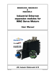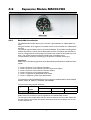
1
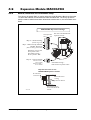
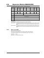
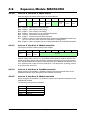
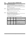
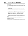
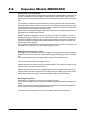
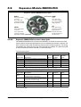
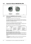
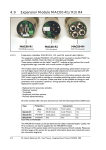
4.6
Expansion Module MAC00-FD4
FD4
MAC00-FD4
With M12 connectors
4.6.1
TT1018GB
DeviceNet Introduction
The MAC00-FD4 module allows you to connect a JVL MacMotor to a DeviceNet network.
Using this module, all the registers in the MAC motor can be accessed over a DeviceNet
network.
The module supports Baud-rates of 125, 250 and 500kbit. The module includes galvanic
isolation between the motor and the DeviceNet network. The Baud-rate and node id
must be configured via the internal dip switch before the module is connected to the network. The module supports polled IO with 8 bytes in and 8 bytes out.
The specification of the IO is according to the position controller device type.
Important:
Please refer to the following sections of the DeviceNet specifications for additional information:
1
2
3
4
5
6
Volume II, Section 3-12: Position Controller.
Volume II, Section 6-24: Position Controller Supervisor Object.
Volume II, Section 6-25: Position Controller Object.
Volume II, Section 6-14: Parameter Object.
Volume I, Appendix H: DeviceNet Error Codes
Volume I, Appendix J: Data Type Specification
The expansion module MAC00-FD4 can be mounted in standard MAC motors MAC50,
MAC95, MAC140, MAC141, MAC400, and MAC800.
The connectors are grouped as follows:
Type
MAC00-FD4
Protection
Connectors
class
I/O and interface
Power supply
Bus interface
IP67/IP65*
M12
M12
M12 (x2)
Note*: IP65 on MAC400-800
Cables with M12 connectors can be supplied for the MAC00-FD4 module.
The first part of this section deals with the software features of the module. Please see
the later pages of this section for specific information about the hardware such as connection schemes etc.
208
JVL Industri Elektronik A/S - User Manual - Integrated Servo Motors MAC050 - 3000
4.6
4.6.2
Expansion Module MAC00-FD4
Terminology / Symantics
This chapter is ment to give an overall understanding of the fundamentals in terminology
concerning the description of the MAC00-FD4 module.
Numbering:
All values are specified in decimal unless other is noted.
0x1234 or #1234 (omron format) specify a hexadecimal number.
General terms:
Command message.
A message sent from the master to the FD4 module describing a certain.
IO-message.
An IO-message is a bundle of 8 bytes sent to the MAC00-FD from the master in the
system and visa versa.
Register.
A register is a physical memory location in the basic motor. All variables to be written
or read a available as a register. For example the desired motor velocity can be set
by writting to register 5. For a general motor register overview please consult MacTalk communication, page 357.
JVL Industri Elektronik A/S - User Manual - Integrated Servo Motors MAC050 - 3000
209
4.6
4.6.3
Expansion Module MAC00-FD4
Node-id, Baud-rate and Termination setup
The 10-way dip switch (SW1) is used to select the node ID and the Baud-rate. Switches
1-6 select the node ID, and switches 8-9 select the Baud-rate. The 2-way dip switch
(SW2) is used to enable termination. When both switches are on, the termination is enabled.
MAC00-FD4 Dip switch settings
Mini dip-switch
OFF
Dip 1-6 - Node-id setting
(address range 0-63)
Dip 7 - Node-id set by software
Dip 8-9 - Baud rate
(Baud rate setting 125k to 500k)
Dip-switch 10 is not used.
Set in position “ON”.
SW1 default settings =
all set in position “ON”
Dip 1-2 - Line termination
Both set to ON =
Term. enabled
Both set to OFF =
Term. disabled
ON
Rear side of the MAC00-FD4
expansion module
1
2
3
4
5
6
7
8
9
0
SW1
1
2
SW2
SW2 default settings =
Both switches in position “OFF”
Dip-switch location on the
MAC00-FD4 Expansion module
M12 external
connectors
Basic MAC motor
housing
Internal circuit boards
TT1017GB
210
Dip Switches placed
on the rear side of the
module
JVL Industri Elektronik A/S - User Manual - Integrated Servo Motors MAC050 - 3000
4.6
Expansion Module MAC00-FD4
The node-id can be set according to the below table:
Node-id
Dip Switch no. (SW1)
6
0
5
4
3
2
Node-id
1
Reserved (illegal setting)
Dip Switch no. (SW1)
6
5
32
ON
OFF
4
3
2
1
OFF OFF
OFF
OFF
1
OFF
OFF
OFF
OFF OFF
ON
33
ON
OFF
OFF OFF
OFF
ON
2
OFF
OFF
OFF
OFF
ON
OFF
34
ON
OFF
OFF OFF
ON
OFF
3
OFF
OFF
OFF
OFF
ON
ON
35
ON
OFF
OFF OFF
ON
ON
4
OFF
OFF
OFF
ON
OFF
OFF
36
ON
OFF
OFF
ON
OFF
OFF
5
OFF
OFF
OFF
ON
OFF
ON
37
ON
OFF
OFF
ON
OFF
ON
6
OFF
OFF
OFF
ON
ON
OFF
38
ON
OFF
OFF
ON
ON
OFF
7
OFF
OFF
OFF
ON
ON
ON
39
ON
OFF
OFF
ON
ON
ON
8
OFF
OFF
ON
OFF OFF
OFF
40
ON
OFF
ON
OFF
OFF
OFF
9
OFF
OFF
ON
OFF OFF
ON
41
ON
OFF
ON
OFF
OFF
ON
10
OFF
OFF
ON
OFF
ON
OFF
42
ON
OFF
ON
OFF
ON
OFF
11
OFF
OFF
ON
OFF
ON
ON
43
ON
OFF
ON
OFF
ON
ON
12
OFF
OFF
ON
ON
OFF
OFF
44
ON
OFF
ON
ON
OFF
OFF
13
OFF
OFF
ON
ON
OFF
ON
45
ON
OFF
ON
ON
OFF
ON
14
OFF
OFF
ON
ON
ON
OFF
46
ON
OFF
ON
ON
ON
OFF
15
OFF
OFF
ON
ON
ON
ON
47
ON
OFF
ON
ON
ON
ON
16
OFF
ON
OFF
OFF OFF
OFF
48
ON
ON
OFF OFF
OFF
OFF
17
OFF
ON
OFF
OFF OFF
ON
49
ON
ON
OFF OFF
OFF
ON
18
OFF
ON
OFF
OFF
ON
OFF
50
ON
ON
OFF OFF
ON
OFF
19
OFF
ON
OFF
OFF
ON
ON
51
ON
ON
OFF OFF
ON
ON
20
OFF
ON
OFF
ON
OFF
OFF
52
ON
ON
OFF
ON
OFF
OFF
21
OFF
ON
OFF
ON
OFF
ON
53
ON
ON
OFF
ON
OFF
ON
22
OFF
ON
OFF
ON
ON
OFF
54
ON
ON
OFF
ON
ON
OFF
23
OFF
ON
OFF
ON
ON
ON
55
ON
ON
OFF
ON
ON
ON
24
OFF
ON
ON
OFF OFF
OFF
56
ON
ON
ON
OFF
OFF
OFF
25
OFF
ON
ON
OFF OFF
ON
57
ON
ON
ON
OFF
OFF
ON
26
OFF
ON
ON
OFF
ON
OFF
58
ON
ON
ON
OFF
ON
OFF
27
OFF
ON
ON
OFF
ON
ON
59
ON
ON
ON
OFF
ON
ON
28
OFF
ON
ON
ON
OFF
OFF
60
ON
ON
ON
ON
OFF
OFF
29
OFF
ON
ON
ON
OFF
ON
61
ON
ON
ON
ON
OFF
ON
30
OFF
ON
ON
ON
ON
OFF
62
ON
ON
ON
ON
ON
OFF
31
OFF
ON
ON
ON
ON
ON
63
ON
ON
ON
ON
ON
ON
JVL Industri Elektronik A/S - User Manual - Integrated Servo Motors MAC050 - 3000
211
4.6
Expansion Module MAC00-FD4
The Baud-rate can be set according to the below table:
Baud-rate
Dip Switch no. (SW1)
10
9
8
7
1-6
125 kbit
X
OFF
OFF
X
See table above
250 kbit
X
OFF
ON
X
See table above
500 kbit
X
ON
OFF
X
See table above
Reserved
X
ON
ON
X
See table above
X = Not used. For future purposes - set in position off
212
JVL Industri Elektronik A/S - User Manual - Integrated Servo Motors MAC050 - 3000
4.6
4.6.4
Expansion Module MAC00-FD4
IO-messages.
The JVL MAC00-FD module offers 8 byte I/O.
These bytes are organized in a standard frame specified by the ODVA organisation.
Depending on what kind of information that is needed different message types are used.
Message types are organized in the lower bit 0-4 in byte 2 and the different message
types supported are:
0x1: "Target position"
0x2: "Target velocity"
0x3: "Acceleration"
0x5: "Torque"
0x1B: "Position controller attribute"
0x1F: "Parameter" (register)
For setting a target position the Command Message type 0x1 is used. Accessing registers
directly in the motor message type 0x1F is used. For a general motor register overview
please consult MacTalk communication, page 357.
The outputs define a Command message covering the message types 0x1, 0x2, 0x3, 0x5
with the following format:
Byte
7
6
5
4
3
2
1
0
0
Enable
-
Hard stop
Smooth
stop
Direction
(vel. mode)
-
-
Load
Data
1
0x1
2
0x1
Command message type
3
0x1
Response message type
4
Data value byte 0
5
Data Value byte 1
6
Data Value byte 2
7
Data Value byte 3
Corresponding response frame from the motor is formated in the following way.
The message frame for the types 0x1, 0x2, 0x3, 0x5.
Byte
7
6
5
4
3
2
1
0
0
Enable
-
Hard Stop
Smooth
Stop
Direction
(V. Mode)
-
-
Load
data
Reverse
limit
Forward
limit
-
1
2
3
0x1
Load
Complete
0x1
-
-
-
Response Message Type
4
Data value byte 0
5
Data Value byte 1
6
Data Value byte 2
7
Data Value byte 3
JVL Industri Elektronik A/S - User Manual - Integrated Servo Motors MAC050 - 3000
213
4.6
Expansion Module MAC00-FD4
The message frame for the type 0x1F is formatted according to the following:
Byte
7
6
5
4
3
2
1
0
0
Enable
-
Hard stop
Smooth
stop
Direction
(vel. mode)
-
-
Load
Data
1
2
Register number to get
0x1
Command message type
3
Register number to set
4
Data value byte 0
5
Data Value byte 1
6
Data Value byte 2
7
Data Value byte 3
The procedure is to setup the frame with the correct values and then set the "Load" -bit
in byte 0 as the last operation. This will load the frame into the motor and thereby set
the register value desired.
In response the motor will return a "Response" frame with the data from the register value that has been requested in the sent frame.
Semantics:
Load Data: Transition from 0->1 initiates the data loading in the motor. The frame is
setup with all data and then this bit is set to make the motor load the data.
Direction:
When the motor is used in velocity mode this bit is used to control the direction of the movement. When velocity mode is used through
Smooth stop: Bring the motor to stop using standard configured deceleration
(deceleration ramp is the same as the acceleration ramp).
214
Hard stop:
Bring the motor to an immediate stop.
Enable:
Bring the motor into an active mode clearing this bit will bring the motor
into "Passive" -mode.
JVL Industri Elektronik A/S - User Manual - Integrated Servo Motors MAC050 - 3000
4.6
Expansion Module MAC00-FD4
The response frame from the motor is formated as follows.
Byte
7
6
5
4
3
2
1
0
0
Enable
-
-
-
General
fault
On Target
position
-
Profile in
progress
Reverse
limit
Forward
limit
-
1
2
3
Register number to get
Load
Complete
-
-
-
-
0x1
0x1F
4
Data value byte 0
5
Data Value byte 1
6
Data Value byte 2
7
Data Value byte 3
Semantics:
Load complete: Indicates that the motor has read the frame.
Reverse limit: By using limit switches to limit the travel distance of the motor this bit
indicates that the motor encountered the reverse limit switch at the input.
Forward limit: By using limit switches to limit the travel distance of the motor this bit
indicates that the motor encountered the forward limit switch at the input.
4.6.5
Object class 0x64.
Each instance has 2 attributes.
With this class all parameters in the motor can be written and read.
The instance number refers to the parameter number in the motor.
Attribute 1 = Value
Attribute 2 = Parameter size in bytes
JVL Industri Elektronik A/S - User Manual - Integrated Servo Motors MAC050 - 3000
215
4.6
4.6.6
Expansion Module MAC00-FD4
Object class 0x65
Instance 1 (I/O Setup)
Attribute ID Access rule Data type Description
Parameter
mapping
The total number of supported
attributes
-
Reserved
-
1
Get
USINT
2
-
-
3
Get
BYTE
Show the input status. IN1-4, NL, PL
240 (0xF0)
4
Get/Set
BYTE
Set the output level
241 (0xF1)
5
Get/Set
BYTE
Input active level
242 (0xF2)
6
Get/Set
BYTE
Input setup
243 (0xF3)
7
Get/Set
BYTE
Output setup
244 (0xF4)
Instance 2 (Status)
Attribute ID Access rule Data type Description
1
Get
USINT
2
-
-
3
Get
BYTE
Parameter
mapping
The total number of supported
attributes
-
Reserved
-
Motor status
245 (0xF5)
Instance 3 (Commands)
Attribute ID Access rule Data type Description
216
Parameter
mapping
The total number of supported
attributes
-
Reserved
-
1
Get
USINT
2
-
-
3
Get/Set
BYTE
Module setup
246 (0xF6)
4
Set
USINT
Execute FastMac Command
247 (0xF7)
5
Set
USINT
MAC00-FDx command
248 (0xF8)
JVL Industri Elektronik A/S - User Manual - Integrated Servo Motors MAC050 - 3000
4.6
4.6.7
Expansion Module MAC00-FD4
Instance 1, Attribute 3, Input status
This object is used to read out the actual value of the inputs.
Bit
7
Input
4.6.8
6
Reserved
5
4
3
2
1
0
PL
NL
IN4
IN3
IN2
IN1
Instance 1, Attribute 4, Outputs
With this object the outputs can be controlled.
The value written to this object is directly shown on the outputs if the output is not set
to use its default function (see attribute 7).
Bit
7
6
5
Output
4.6.9
2
Reserved
7
Input
1
0
O2
O1
6
Reserved
5
4
3
2
1
0
PL
NL
IN4
IN3
IN2
IN1
Instance 1, Attribute 6, Input setup
With this object, the dedicated function of the inputs can be enabled. When the corresponding bit is 0 the input function is as a normal input. When the corresponding bit is 1
the dedicated function of the input will be enabled. When the end limit inputs NL or PL
are enabled and one of these is activated, the error action will be executed. The error
action is defined in instance 3, attribute 3.
Bit
7
Input
4.6.11
3
Instance 1, Attribute 5, Input active level
With this object the active level of the inputs can be selected. When bit x = 0 the input
is active low and when bit x = 1 the input is active high.
The default setup for the output is active high.
Bit
4.6.10
4
6
Reserved
5
4
PL
NL
3
2
1
0
Reserved
Instance 1, Attribute 7, Output setup
This object is used to control the function of the outputs. When bit x = 0 the output is
controlled by attribute 4.
When bit x = 1 the output is controlled by the default function. The default function for
O1 is ’In position’ and for O2 ’Error’.
Bit
Output
7
6
5
4
Reserved
3
2
1
0
O2
O1
JVL Industri Elektronik A/S - User Manual - Integrated Servo Motors MAC050 - 3000
217
4.6
4.6.12
Expansion Module MAC00-FD4
Instance 2, Attribute 3, Motor status
With this object, the status of the motor can be monitored.
Bit
7
6
5
4
3
2
1
0
Data
-
Deceleration
Acceleration
In
position
-
Limit
switch
error
Disconnected
Motor
error
Bit 7:
Bit 6:
Bit 5:
Bit 4:
Bit 3:
Bit 2:
Bit 1:
Unused - reserved for future purposes.
Equals 1, if the velocity is decreasing.
Equals 1, if the velocity is increasing.
Equals 1, if the motor is in the commanded position.
Unused - reserved for future purposes.
Equals 1, if a limit switch has been activated.
Equals 1, if there is a communication error between the MAC00-FDx and the motor. This can occur if the motor was reset due to a voltage drop.
Bit 0: Equals 1, if there is a fatal motor error. Read subindex 4 for extended information.
4.6.13
Instance 3, Attribute 3, Module setup bits
This object is used for auxiliary setup of the module.
Bit
Setup
7
6
Endless
relative
Error
action
5
4
3
2
1
0
Reserved
Endless relative: When this bit is 1, the endless relative position mode is used for incremental positioning. When using this mode, absolute positioning can no longer be used.
Error action: Determines the action in the event of an error. Bit6 set to 0 will set the motor in passive mode in case of an error, Bit6 set to 1 will stop motor by setting velocity
to 0 in the event of an error.
4.6.14
Instance 3, Attribute 4, FastMac command
When writing to this attribute, a FastMac command is executed. Please refer to the
MAC00-FPx section for a description of the FastMac commands.
4.6.15
Instance 3, Attribute 5, Module command
When writing to this attribute, it is possible to execute some special commands on the
MAC00-FDx module.
The following commands are available:
218
Number
Function
0
No operation
1
Reset limit error
2
Reset communication error
3-255
Reserved
JVL Industri Elektronik A/S - User Manual - Integrated Servo Motors MAC050 - 3000
4.6
Expansion Module MAC00-FD4
4.6.16
Object class 0xF (Parameter)
This object class is the parameter class defined by the DeviceNet standard.
The attributes that are mapped into this object are from object class 0x64 and 0x65.
Instance 0-239 is mapped to the value attribute in object class 0x64 from the corresponding instance.
Instance 240-255 is mapped to attributes from object class 0x65. Refer to the description
of this object class for the mappings.
4.6.17
Object class 0x24 (Position Controller Supervisor)
This object class is the Position controller supervisor object, as defined in the DeviceNet
standard.
The following class attributes are supported: 1,2,3,6,32,33.
The following attributes are supported for instance 1: 1,3,5,6,7.
4.6.18
Object class 0x25 (Position Controller)
This object class is the position controller object, as defined in the DeviceNet standard.
The following attributes are supported for instance 1:
1,2,3,6,7,8,10,11,12,13,14,17,20,21,25,45,48,49,52,54,55,58.
The range for attribute 25:Torque is 0-1023.
The following additional manufacturer-specific attributes are supported:
Attribute ID Access rule Data type Description
Search mode. This mode will be used next time the controller is enabled and the selected mode is position. This
value will be cleared after the enable.
100
Get/Set
USINT
101
Get/Set
DINT
The Zero search offset in counts
102
Get/Set
DINT
The velocity to use during Zero search in encoder counts
per second.
103
Get/Set
DINT
The torque limit to use during Zero search. The range is
-1023 to 1023. A negative torque value means that the
zero sensor is active low.
104
Get/Set
BOOL
Use Index. If this is enabled, the zero point will be corrected with reference to the motors index mark.
JVL Industri Elektronik A/S - User Manual - Integrated Servo Motors MAC050 - 3000
219
4.6
4.6.19
Expansion Module MAC00-FD4
Examples - Typical needed actions in a DeviceNet system.
A number of typical actions is often needed in a system with DeviceNet interface to perform the desired operation in the system.
This chapter have some important guidelines on how to handle these typical actions and
issues.
Addressing registers in the motor using explicit messaging and I/O-messages.
Although the basic positioning handling is done using the standard Position controller specified from the ODVA organisation it is sometimes necessary to access the registers directly. This section covers the various ways of doing this on top of a more thorough
explanation on the different data formats. For a general motor register overview please
consult MacTalk communication, page 357.
Register addressing in the motor:
To access the registers in the motor there are 2 ways of doing this. Either use explicit
messages or the I/O message approach.
Explicit register access:
To access the registers in the motor explicit (not cyclic), use the object 0x64 with the
instance number as a reference to the register number and the attribute as the
amount of bytes that needs to be handled.
Example: The velocity of the motor needs to be set. In order to do this the velocity
register (register 5 named “V_SOLL”) must be used.
To setup the explicit message, setup the following parameters as follows:
Object 0x64
Instance: 5 (register 5, V_SOLL register)
Attribute 1: Data (for write operation)
Attribute 2: Bytes (write operation)
I/O-message access (cyclic transmission):
To gain access to the motor registers directly using the I/O-message approach simply
use the command message type 0x1F. Please see IO-messages., page 213 in order to
see deatails concerning the 0x1F message frame.
JOG function.
Often it is necessary to run the motor a certain distance in positive or negative direction
in order to find a certain reference point or similar.
The MAC motor can be controlled in several different modes. Typically used modes are
“Position" -mode for positioning purpose or "Velocity" -mode which control the motor
movement without taking any notice of the actual position.
If a JOG function is needed it is strongly recommended to use the velocity mode since
the position mode or related modes involves a number of registers and is more complex
compared to the velocity mode.
In velocity mode, none of the position related registers are of particular interest but the
actual position counter is still updated continuously.
220
JVL Industri Elektronik A/S - User Manual - Integrated Servo Motors MAC050 - 3000
4.6
Expansion Module MAC00-FD4
Performing the JOG function in velocity only requires that the velocity register (V_SOLL
- register 5) is used.
A way of implementing "JOG" -functionality is basically to change actual mode to "Velocity" and control the velocity and acceleration.
The following guideline can be used.
1. Set velocity = 0 (register 5 ), to avoid immediate movement when the mode is
changed to velocity.
2. Change the mode to Velocity mode (register 2 = 1), now the mode is changed but
the velocity is set to 0 so the motor stay stationary.
3. According to the direction, change the velocity to a positive value to run CW or negative to run CCW. Please remember that this value is scaled depending on the motor
type used. The value is written into the velocity register (register 5 / V_SOLL)
MAC50-140 the scaling is [RPM] x 2.097, so 1000 RPM = 2097 [counts/smpl.]
MAC400 the scaling is [RPM] x 2.837, so 1000 RPM = 2837 [counts/smpl.]
MAC800 the scaling is [RPM] x 2.771, so 1000 RPM = 2771 [counts/smpl.]
4. To stop the motor set the velocity to 0. This will force the motor to decelerate and
stay stationary keeping the actual position obtained after running with a velocity > 0.
Optional:
If the motor needs to be switched into a position related mode the actual position counter and some other position related registers need to be modified or reset.
Otherwise the motor will return to the original motor position which was present before
the JOG function was executed.
A simple way of doing this, is to send the special command 247 to the “Special command"
-register, register number 211.
JVL Industri Elektronik A/S - User Manual - Integrated Servo Motors MAC050 - 3000
221
4.6
Expansion Module MAC00-FD4
Zero search - how to activate.
In almost any system which is using some kind of position related mode it is necessary to
find the mechanical zero point before normal operation of the motor can take place.
Following description gives a guide line on how to activate the build-in Zero search function.
It is necessary to determine which kind of Zero search type that needs to be activated.
The MAC motors offers a number of various Zero search types. Please consult the chapter Mechanical Zero search, page 32 which explain in details which Zero search functions
that exist and how they perform the Zero search.
Please find the section specifying the object 0x25 that can be accessed explicitly for configuration from the Devicenet network.
Another method for doing Zero search is to setup the motor for doing Zero search at
startup selecting one of the “Power-up” Zero search modes. This can be done from the
MacTalk configuration software and can be setup permanent in the motor without any
further actions done through the DeviceNet interface. Please consult the chapter Mechanical Zero search, page 32.
If this method is prefered the motor will automaticaly perform the Zero search every time
the motor is powered up or the 24V control supply is cycled.
Reading and clearing error codes.
The register 35 is a combined error/status -register that represent the actual information
about errors and the current motor status (accelerating, decelerating, motor in position)
etc.
All this information is put into a single register that can be read all the time.
To clear the errors either write register 35= 0
Another method is to execute the special command 225. This is done by writing to register 211 which will clear any actual errors.
Please notice that some errors are regarded as fatal and needs 24V power cycle to be
cleared. Please consult the chapter Error messages and error handling, page 40 for further
details about all the error types and what may have caused the error situation.
Resetting the position.
Sometimes it is necessary to reset the actual position counter.
When done manually it requires writing to multiple registers and special handling of the
motor.
All this can be done by sending a the special command 247 to the command register 211
which will set the actual and requested position = 0.
The motor will stay stationary if it is set in a position related mode afterwards.
222
JVL Industri Elektronik A/S - User Manual - Integrated Servo Motors MAC050 - 3000
4.6
4.6.20
Expansion Module MAC00-FD4
Example - How to implement with a Omron PLC:
How to implement a JOG function using Omron PLC system.
This example sets the motor into velocity mode and sets a velocity depending on which
direction to go and returns in Position mode when the joggin is finished.
Notice that Omron uses the syntax #1234 indicating a hexadecimal number in contrast
to elsewhere in this chapter where the syntax 0x1234 is used for indicating a hexadecimal
number.
1. Start by setting the velocity to 0, to prevent the motor from moving anywhere when
the mode is set to "velocity".
Please observe that all values are 16bit and refers to the cyclic IO of 8 bytes each way.
Please find the section covering IO-messages.
Basically this example uses the Register message type and accesses the registers relevant for this operation. That is P_SOLL, V_SOLL and the mode register.
Word 0: #0381
Word 1: #053F
Word 2: #0000
Word 3: #0000
;Set the bits in the structure and get register 3=P_IST actual position
;Register 5, V_SOLL, use command message = 31 + 32
;Value=0
;Value=0
2. Next step is to set the motor into velocity mode by writing register 2 = 1:
Word 0: #0381
Word 1: #023F
Word 2: #0001
Word 3: #0000
;Set the bits in the structure and get register 3=P_IST actual position
;Register 2, MODE, use command message = 31 + 32
;Value=1, velocity mode
;Value=0
3. Now we set the velocity depending on which direction we want to use, we set either
positive or negative value, we will set register 5, V_SOLL for this purpose.
Word 0: #0381
Word 1: #053F
Word 2: #07D0
Word 3: #0000
;Set the bits in the structure and get register 3=P_IST actual position
;Register 5, MODE, use command message = 31 + 32
;Value=2000, velocity mode appx. 957 RPM (scaling: 2.1 x RPM)
;-
4. Now the motor runs CW looking on the shaft.
If we want to go the other way we send:
Word 0: #0381
Word 1: #053F
Word 2: #F830
Word 3: #FFFF
;Set the bits in the structure and get register 3=P_IST actual position
;Register 5, MODE, use command message = 31 + 32
;Value=-2000, velocity mode appx. -957 RPM (scaling: 2.1 x RPM)
;-
5. If a motor stop is desired now there is several ways, one way is to set velocity = 0:
Word 0: #0381
Word 1: #053F
Word 2: #0000
Word 3: #0000
;Set the bits in the structure and get register 3=P_IST actual position
;Register 2, MODE, use command message = 31 + 32
;Value=0
;-
JVL Industri Elektronik A/S - User Manual - Integrated Servo Motors MAC050 - 3000
223
4.6
Expansion Module MAC00-FD4
6. Now the motor is stopped at a stationary position, this position we want to set to 0,
so we are using a special command. Write to command register 211. The command is
247:
Word 0: #0381 ;Set the bits in the structure and get register 3=P_IST actual position
Word 1: #D33F ;Register 211, Command, use command message = 31 + 32
Word 2: #00F7 ;Value=247
Word 3: #0000 ; This will set the 2 registers P_IST = P_NEW and P_SOLL = P_NEW per default
P_NEW = 0, so this will automatically set these registers to 0.
P_NEW has register number 163.
7. Now return to standard position control.
We set the mode back to position (remember, velocity = 0):
Word 0: #0381
Word 1: #023F
Word 2: #0002
Word 3: #0000
;Set the bits in the structure and get register 3=P_IST actual position
;Register 2, Command, use command message = 31 + 32
;Value=2 = position mode
;-
8. Next we must set the max. velocity to use
Word 0: #0381 ;Set the bits in the structure and get register 3=P_IST actual position
Word 1: #053F ;Register 5, MODE, use command message = 31 + 32
Word 2: #07D0 ;Value=2000, velocity mode appx. 957 RPM (scaling: 2.1 x RPM)
Word 3: #0000 ;
9. From here we can either use the standard position controller and change the message
type to "Target position" and maybe set the incremental -bit if necessary.
Word 0: #0381 ;Set the bits in the structure and get register 3=P_IST actual position
Word 1: #2121 ;Use target position message type
Word 2: #07D0 ;Value=2000, since we are running "incremental" the shaft position
;is moved by 2000 counts
Word 3: #0000 ; .........
Please also consult the user documentation for the Omron PLC and for a general motor
register overview please consult MacTalk communication, page 357.
224
JVL Industri Elektronik A/S - User Manual - Integrated Servo Motors MAC050 - 3000
5
4
2
JVL Industri Elektronik A/S - User Manual - Integrated Servo Motors MAC050 - 3000
1
M12 Female connector
“BUS2”
DeviceNet Interface
M12 Male connector
“BUS1”
DeviceNet Interface
7
1
3
6
4
5
5
2
8
2
O2
3
3
5
DeviceNet
Transceiver +
DC-DC conv.
RS232
serial interface
Optocoupler
+ Driver
Optocoupler
Opto-isolation
V-
CAN_L
CAN_H
V+
Rx
4
Tx-PD
Tx
1
2
O1
4
IO-
O+
PL
NL
IN1
2
6
Interface
Control
Control
core
Power supply for the module
Power ground (P-) is not connected in the MAC00-FD4 module
6
5
SW3
CV
1
4
3
“I/O”
Digital inputs and outputs
Voltage range 5-28 (32)V
3
1
P+
P-
MAC00-FD4 expansion module
GND
TX
RX
AIN
GND
O1
O2
B
B+
A
A+
5V
P+
P-
Asynchronous
interface (5V)
TT1019GB
or Zero search input
±10V nom. or up to 32V
Analogue input
Status outputs
Multifunction I/O
(setup as “serial data”)
Internal power supply
(processor and encoder)
Power supply
(MAC050 to 800)
Basic MAC motor
4.6.21
2
MAC50-141: +12-48V and MAC400/800: +24V
“PWR”
Power supply
Basic MAC motor with MAC00-FD4 module inserted.
4.6
Expansion Module MAC00-FD4
Hardware in general
The schematic below shows the MAC00-FD4 module mounted inside the basic MAC
motor. For further details regarding the external connectors, please see Expansion
MAC00-FD4 hardware description, page 226
225
4.6
Expansion Module MAC00-FD4
Expansion module MAC00-FD4 front plate
PWR
BUS1
Power
M12 - 5pin male
connector including:
P+, P- and secondary
supply (optional).
Primary DeviceNet
connector.
M12 - 5pin male
connector including:
DeviceNet interface
I/O
M12 - 8pin female
connector including:
RS232 Interface
Selectable I/O’s such
as analogue input, O1,
O2, IN1, NL, PL.
BUS2
Second DeviceNet
connector
M12 - 5pin female
connector including:
DeviceNet interface
FD4
TT1016GB
4.6.22
Expansion MAC00-FD4 hardware description
The MAC00-FD4 offers IP67 protection on MAC050-141 and M12 connectors which
make it ideal for automation applications where no additional protection is desired. The
M12 connectors offer solid mechanical protection and are easy to operate. The I/O signals available are restricted since only 4 I/O terminals are available. The I/Os connected
to these 4 terminals must be selected via a small dip-switch.
The connector layout:
“PWR” - Power input. M12 - 5-pin male connector
Signal name
Description
Pin no.
JVL Cable
WI1000M12
F5T05N
P+
Main supply +12-48VDC. Connect with pin 2 *
1
Brown
1
P+
Main supply +12-48VDC. Connect with pin 1 *
2
White
1
P-
Main supply ground. Connect with pin 5 *
3
Blue
1
CV
Control voltage +12-48VDC.
4
Black
1
P-
Main supply ground. Connect with pin 3 *
5
Grey
1
Isolation
group
* Note: P+ and P- is each available at 2 terminals. Make sure that both terminals are connected in order to
split the supply current in 2 terminals and thereby avoid an overload of the connector.
“BUS1” - DeviceNet interface. M12 - 5-pin male connector
Signal name
Description
Pin no.
Cable: user
supplied
Isolation
group
Drain
Shield for the DeviceNet interface - internally
connected to the motor housing
1
-
2
V+
DeviceNet supply. Note that the MAC00-FP4
only senses at this terminal. The MAC00-FP4
contains its own power supply
2
-
2
V-
DeviceNet ground
3
-
2
CAN_H
DeviceNet interface. Positive signal line
4
-
2
CAN_L
DeviceNet interface. Negative signal line
5
-
2
(Continued next page)
226
JVL Industri Elektronik A/S - User Manual - Integrated Servo Motors MAC050 - 3000
4.6
Expansion Module MAC00-FD4
“BUS2” - DeviceNet interface. M12 - 5-pin female connector
Signal name
Description
Pin no.
Cable: user
supplied
Isolation
group
Drain
Shield for the DeviceNet interface - internally connected to the motor housing.
1
-
2
V+
DeviceNet supply. Note that the MAC00-FP4 only
senses at this terminal. The MAC00-FP4 contains
its own power supply.
2
-
2
V-
DeviceNet ground.
3
-
2
CAN_H
DeviceNet interface. Positive signal line.
4
-
2
CAN_L
DeviceNet interface. Negative signal line.
5
-
2
“IO” - I/O’s and RS232 interface. M12 - 8-pin female connector.
Signal name
Description
Function
Pin no.
JVL Cable
WI1000-M12
M8T05N
IOC
I/O terminal C.
SW3-5 = OFF : PL input
SW3-5 = ON : O1 output
1
White
3
Tx
RS232 interface - transmit output
Important !: DIP1 must be turned ON. If addressing is
used it must be turned ON at minimum one
of the connected motors.
2
Brown
1
Rx
RS232 interface - receive input
3
Green
1
GND
RS232 Ground - also used with analogue input
4
Yellow
1
5
Grey
3
(1 when
used as
AIN)
Isolation
group
IOA
I/O terminal A.
SW3-2 = ON and SW3 DIP3 = OFF :
AIN (Analogue input)
SW3-2 = OFF and SWDIP 3 = ON :
O2 (output 2)
(AIN is the analogue input. Remember to use the GND terminal with
AIN)
IOB
I/O terminal B.
SW3-4 = OFF : IN1 (input 1)
SW3-4 = ON : O1 (output 1)
6
Pink
3
IO-
I/O ground to be used with IN1, NL, PL, O1, O2
7
Blue
3
8
Red
3
IOD
I/O terminal D.
SW3-6 = OFF : NL
(negative limit input)
SW3-6 = ON : O+
(output supply)
Cable Screen
Some standard cables with M12 connector offer a screen around the cable. This screen on some cables is
fitted to the outer metal of the M12 connector. When fitted to the MAC00-FD4 module, this means that the
screen will have contact with the complete motor housing and thereby also the power ground (main ground).
Isolation groups
The MAC00-FD4 offers optical isolation at the digital inputs and outputs (IN1, NL, PL and O1-2). The table
shows a number for each pin. This number refers to the isolation group to which the pin is connected.
Isolation group 1 means that the terminal refers to the main ground (P-, GND and the motor housing).
Isolation group 2 means that the terminal refers to the DeviceNet interface ground (V-).
Isolation group 3 means that the terminal refers to the I/O ground (IO-)
Defaults: Dip1-6 : ON, ON, OFF, OFF, ON, ON = TXPD:ON / IOA:AIN / IOB:IN1 / O1 / O+
4.6.23
General wirering considerations
Due to the nature of Devicenet needing a handshake procedure at initialization it is NOT recommended to power cycle 24V while the Devicenet bus system is running. If MAC400/800 motor
types are used, keep the 24V control power on but cut the AC-voltage for the motor. In this way
the DeviceNet connection is kept but the motor is held powerless and all motor movement is
inhibited.
For the smaller series of MAC-motors (50-141) there is a separate power connection for the motor driver (P+ terminal) which can be disabled while the control power (the CV terminal) is kept
supplied with 24VDC without loss of communication.
JVL Industri Elektronik A/S - User Manual - Integrated Servo Motors MAC050 - 3000
227
4.6
4.6.24
Expansion Module MAC00-FD4
Connecting MAC00-FD4 to the DeviceNet-bus
Before you connect the MAC00-FD4 to the DeviceNet-bus make sure that the Baudrate, the Node-ID and the termination is setup to the desired values.
On the DeviceNet bus it is possible to have a transmission speed (Baud-rate) of maximum 500 Kbit/s and a minimum of 125 Kbit/s. The Baud-rate depends on the cable
length, and the wires cross-section. The table below have some recommendations for
networks with less than 64 nodes. Recommended bus cable cross-section are according
to CiA®:
Bus Distance
(m)
Cross-section (mm2)
Terminator
(ohm)
Baud-rate
(Kbit/s)
100
0.34-0.6
150-300
500
250
0.34-0.6
150-300
250
500
0.5-0.6
150-300
125
The bus wires may be routed in parallel, twisted and/or shielded, depending on EMC requirements. The layout of the wirering should be as close as possible to a single line structure, in order to minimize reflections. The cable stubs for connection of the bus node
shall be as short as possible, especially at high bit rates. The cable shielding in the house
shall have a large contact area. For a drop cable a wire cross-section of 0.25 to 0.34 mm²
would be an appropriate choice in many cases. In section 4.3.46 of this chapter there is
an overview showing various JVL standard cables. All the JVL cables are twisted and
shielded.
For bus lenghts greater than 500m, a bridge or repeater device is recommended.
Galvanic isolation between the bus nodes is optional. In the MAC00-FD4 modules the
galvanic isolation is integrated to obtain best possible immunity against noise and differences in the voltage potential between the nodes.
228
JVL Industri Elektronik A/S - User Manual - Integrated Servo Motors MAC050 - 3000
4.6
4.6.25
Expansion Module MAC00-FD4
Necessary accessories to MAC-FD4:
On our web page www.jvl.dk you can, under the downloads menu, find the EDS file for
the MAC00-FD4 module, in the menu Field bus Interface Specifications Files.
EDS means Electronic Data Sheet. This file contains the information about the MAC00FD4 settings, that may be required to configure the setup and program in the master.
The MAC00-FD4 is a slave module on the DeviceNet-bus line, the master can be for example a PLC or a PC. If you are using a PLC as master, then make sure that it is provided
with a DeviceNet® communications module, and that the correct programming tools
are available. For getting support to the PLC master, it is more rewarding to use the PLC
vendor.
The MacTalk program can be used to monitor various operations and make the initial set
up on the motor see also Using MacTalk to setup the motor, page 14.
MacTalk is not a free-ware program. Please contact your JVL representative for further
information.
JVL Industri Elektronik A/S - User Manual - Integrated Servo Motors MAC050 - 3000
229
4.6
4.6.26
Expansion Module MAC00-FD4
Hardware I/O setup
The drawing below shows the SW3 Dip-switch location. The various settings of SW3 is
shown on the previous page.
Switch description:
SW3
Description
Function
Signal name
Dip 1
RS232 interface - transmit output
ON = Enable
Tx
Dip 2
Dip 3
I/O terminal A
DIP2=ON and DIP3=OFF :
AIN (Analogue input)
IOA
Dip 2
Dip 3
I/O terminal A
DIP2=OFF and DIP3=ON :
O2 (output 2)
IOA
Dip 4
I/O terminal B
DIP4=ON : Output 1
DIP4=OFF : Input 1
IOB
Dip 5
I/O terminal C
DIP5=ON : O1 output
DIP5=OFF : PL (positive limit input)
IOC
Dip 6
I/O terminal D
DIP6=ON : O+ (Output supply)
DIP6=OFF : NL (Negative limit input)
IOD
The factory default setting is:
SW3
ON
Dip 1
X
Dip 2
Dip 3
X
Function
RS232 interface Enable
X
Dip 4
230
OFF
X
O2 (output 2)
Input 1
Dip 5
X
O1 output
Dip 6
X
0+ (output supply)
JVL Industri Elektronik A/S - User Manual - Integrated Servo Motors MAC050 - 3000
4.6
Expansion Module MAC00-FD4
4.6.27
Cables for the MAC00-FD4
The following cables equipped with M12 connector can be supplied by JVL.
MAC00-FD4 Connectors
Description
JVL Order no.
RS232 Interface cable. Connects
directly from MAC00-FD4 to PC
Length: 5m (197 inch)
RS232-M12-1-8
X
Cable (Ø5.5mm) with M12 female
5-pin connector loose wire ends
0.35mm² (22AWG) and foil screen.
Length: 5m (197 inch)
WI1000-M12F5T05N
X
Same as above but 20m (787 inch)
WI1000-M12F5T20N
X
Cable with M12 male 8-pin
connector loose wire ends
0.22mm² (24AWG) and screen.
Length: 5m (197 inch)
WI1000-M12M8T05N
X
Same as above but 20m (787 inch)
WI1000-M12M8T20N
X
DeviceNet cable with M12 male 5pin connector, loose ends
and screen.
Length: 5m (197 inch).
WI1006-M12M5S05R
X
Same as above but 15m (591 inch)
WI1006-M12M5S15R
X
Devicenet cable with M12 female
5-pin connector, loose
ends and screen.
Length: 5m (197 inch)
WI1006-M12F5S05R
X
Same as above but 15m (591 inch)
WI1006-M12F5S15R
Loose DeviceNet male M12
termination resistor.
WI1008-M12M5STR4
“BUS1”
5-pin
Male
B-coded
“BUS2”
5-pin
Female
B-coded
“I/O”
8-pin
Female
Photo
“PWR”
5-pin
Male
X
Termination resistor
X
Protection caps. Optional if connector is not used, to protect from dust / liquids.
X
X
X
X
IP67 protection cap for M12
female connector.
WI1000-M12FCAP1
IP67 protection cap for M12
male connector.
WI1000-M12MCAP1
Important: Please note that the cables are a standard type. They are not recommended for use in cable chains or where the cable is repeatedly bent. If this is required, use a special robot cable (2D or 3D
cable). See also Accessories, page 394 where additional M12 connectors are shown.
JVL Industri Elektronik A/S - User Manual - Integrated Servo Motors MAC050 - 3000
231