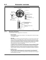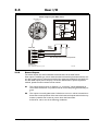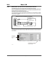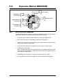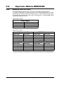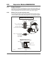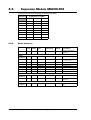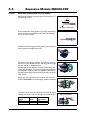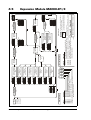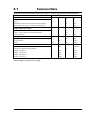
1
MAC50
MAC95
MAC140
MAC141
Including expansion modules
Integrated Servo Motors
User Manual
JVL Industri Elektronik A/S
LB0047-14GB
Revised 4.2.2004
Copyright 1998-2004, JVL Industri Elektronik A/S. All rights reserved.
This user manual must not be reproduced in any form without prior written
permission of JVL Industri Elektronik A/S.
JVL Industri Elektronik A/S reserves the right to make changes to information contained in this manual without prior notice.
Similarly JVL Industri Elektronik A/S assumes no liability for printing errors
or other omissions or discrepancies in this user manual.
MacTalk and MotoWare are registered trademarks
JVL Industri Elektronik A/S
Blokken 42
DK-3460 Birkerød
Denmark
Tlf. +45 45 82 44 40
Fax. +45 45 82 55 50
e-mail: [email protected]
Internet: http://www.jvl.dk
Contents
1
Introduction .................................................................................................................... 5
1.1
1.2
1.3
1.4
Features .............................................................................................................................................................. 6
Overall description ............................................................................................................................................. 7
Expansion modules overview ........................................................................................................................... 10
Setting up the MAC motor ............................................................................................................................... 11
2
Function description ..................................................................................................... 13
2.1
2.2
2.3
2.4
Using Position mode ......................................................................................................................................... 14
Gear Mode ........................................................................................................................................................ 15
Mechanical zero search ..................................................................................................................................... 18
Error Handling .................................................................................................................................................. 22
3
Hardware description ................................................................................................... 23
3.1
3.2
3.3
3.4
Connector overview ......................................................................................................................................... 24
Power Supply .................................................................................................................................................... 25
Serial interface .................................................................................................................................................. 27
User I/O ............................................................................................................................................................ 28
4
Expansion Modules ....................................................................................................... 35
4.1
4.2
4.3
4.4
4.5
Expansion Module MAC00-B1 .......................................................................................................................... 36
Expansion Module MAC00-B2 .......................................................................................................................... 43
Expansion Module MAC00-FC2 ....................................................................................................................... 45
Expansion Module MAC00-FP2 ........................................................................................................................ 57
Expansion Module MAC00-R1/3 ....................................................................................................................... 71
5
Appendix ....................................................................................................................... 85
5.1
5.2
5.3
5.4
5.5
5.6
5.7
5.8
5.9
5.10
Technical Data .................................................................................................................................................. 86
Torque Curves .................................................................................................................................................. 88
Efficiency curve ................................................................................................................................................. 89
Physical Dimensions .......................................................................................................................................... 90
Trouble-shooting guide ..................................................................................................................................... 91
Serial communication ........................................................................................................................................ 93
Connecting to other equipment ....................................................................................................................... 98
Accessories ..................................................................................................................................................... 101
Cable connection tables .................................................................................................................................. 103
CE Declaration of Conformity ........................................................................................................................ 104
JVL Industri Elektronik A/S - User Manual - Integrated Servo Motors MAC50, 95 and 140
3
4
JVL Industri Elektronik A/S - User Manual - Integrated Servo Motors MAC50, 95 and 140
1
Introduction
JVL Industri Elektronik A/S - User Manual - Integrated Servo Motors MAC50-141
5
1.1
Features
TT0940GB
The MAC series of brushless servo motors with integrated electronics represents a major step forward in motion control systems. All of the
necessary electronics for a servo system
are integrated into the motor itself.
Traditional motor systems typically have the controller and drive electronics placed some distance
away from the motor. This increases machine costs
and has the negative effect that installation time and
costs are a major part of the total expense of building machinery.
The basic idea of the MAC motor is to minimise
these costs, but also to make a component that is
much better protected against electrical noise
which can be a typical problem when using long cables between a controller and motor.
All user inputs and outputs are filtered, which
means that the MAC motors will work properly
even in an environment with a high level of electrical
noise.
The major advantages are:
• Lower installation costs
• Faster installation
• Quiet and maintenance-free operation
• Replacement for pneumatic solutions
• Replacement for step motors, offering much
faster response
• Great flexibility due to many I/O possibilities and
many functions.
• Less machine space required.
• Fewer possibilities for wiring errors.
6
Main Features:
• Low cost and high performance make the
MAC series ideal for high-volume applications
• Pulse and direction inputs make it possible
to replace step motors.
• Quadrature input for gearing applications.
• ±10V input for controlling speed and torque
• 2 ch. Quadrature output to master controller when used as driver.
• Accepts position and velocity commands
sent via RS232/422 interface.
• Wide supply voltage range 12 to 48VDC.
• Excellent efficiency compared to
step motors.
• High resolution (4096 cpr) compared to
cost.
• Wide variety of expansion modules which
can be mounted internally:
Profibus DP module
CAN-bus module
Ethernet module
Stand-alone positioning module
Module with AMP military connectors
Custom-designed modules on request
• 2 Outputs for In position and Error
indication.
• 4.th order digital filter which only needs a
single inertia adjustment.
• Standard NEMA23 flange.
• Built-in sensors make the motor stay stationary when powering up.
• Easy and simple Windows program available
for installation/setup.
• High-efficiency MosFet power stage keeps
temperature at a low level.
• CE approved. UL pending.
JVL Industri Elektronik A/S - User Manual - Integrated Servo Motors MAC50-141
1.2
Overall description
Power supply
connector
Basic MAC motor block diagram including motor and feedback devices
+12-48VDC
Ground
User I/O connector
AIN
Analogue
input ±10V
A+
A
Power Dump
for absorbing
regenerative
energy
3-ph. Mos-Fet
driver
Current
Sensing
+5VDC Out
Receive
Transmit
Ground
V
2 channel
differential
Transceiver
A
B
High speed
digital logic
array
2 Digital NPN
outputs showing
motor status
Asynchronous
serial interface
3-phase
brushless
motor
High speed
A/D converter
Analogue input
Level shifter
and filter
B
Output 2
U
W
B+
Output 1
Serial interface
connector
Switchmode
Power
Supply
HU
16 Bit
Microprocessor
HV
HW
1024 ppr
optical
incremental
encoder
Hall
elements
Memory
and system
control
TT0934GB
All the internal building blocks of the MAC motor are shown in the illustration above.
The central microprocessor takes care of all the processes in the motor via the various
I/O blocks such as the serial interface, differential transceiver (Multifunction I/O) and the
motor driver sections.
JVL Industri Elektronik A/S - User Manual - Integrated Servo Motors MAC50-141
7
1.2
Overall description
Motor Type
Continuous
Torque
Peak
Torque
Power
(cont.)
Speed
Flange
Total
length
MAC50
0.11Nm
0.32 Nm
46 Watt
4000 RPM
NEMA23
57x57mm
(2.3”x2.3”)
111.2 mm
MAC95
0.22 Nm
0.62 Nm
92 Watt
4000 RPM
NEMA23
57x57mm
(2.3”x2.3”)
130.5 mm
MAC140
0.32 Nm
0.9 Nm
134 Watt
4000 RPM
NEMA23
57x57mm
(2.3”x2.3”)
152.5 mm
MAC141
0.48 Nm
1.59 Nm
134 Watt
2700 RPM
NEMA23
57x57mm
(2.3”x2.3”)
172.0 mm
The MAC motor is available in 4 different sizes: MAC50, MAC95, MAC140 and
MAC141, with continuous power ratings from 46W to134W. The basic functions and I/
O features are the same for all models.
1.2.1
Basic modes/functions in the MAC motor.
The MAC motor offers the following functions.
-
Velocity mode.
The motor velocity can be controlled using MacTalk software or by sending commands via the serial interface.
-
Position mode
The motor position can be controlled using MacTalk or by sending position commands via the serial interface.
-
Gear mode
The position of the motor is controlled by the multifunction I/O, which is configured
as input. Either a pulse and direction signal can be applied or a quadrature A and B
signal from, for example, an incremental encoder.
This mode is very powerful if the MAC motor is used to upgrade a step motor system
or if the motor is used in electronic gear applications such as a flying saw where an
external encoder tracks the position of a moving object.
-
Analogue Velocity Mode.
The motor velocity is controlled by a voltage applied at the ±10V analogue input.
This mode can be used in several applications but typical applications include maintaining variable but constant speed in feeding mechanisms or as a slave driver in multiaxis systems with a master position controller for several axes.
-
Analogue Velocity (with deadband) Mode.
Same function as Analogue Velocity Mode but a deadband around zero is inserted.
The deadband is +/-600mV. This feature is useful if a potentiometer or similar device
is used to control the speed of the motor since the motor will be stationary if the input voltage is almost at zero.
-
Analogue Velocity/Gear Mode.
This mode is similar to Gear mode but it is possible to increase or decrease the position of the motor by adjusting the voltage applied to the ±10V input. A Typical application is feeding mechanisms that require “on-the-fly” adjustment.
(continued next page)
8
JVL Industri Elektronik A/S - User Manual - Integrated Servo Motors MAC50-141
1.2
Overall description
-
Velocity/Analogue Mode.
The motor torque is fully controlled by a voltage applied at the ±10V analogue input.
This mode is useful if the motor is used for winding applications where a constant
torque is required in the process. Another typical application is as a slave driver in
multi-axis systems with a master position controller for several axes. The update frequency is 521 Hz. Use Analogue Torque (Direct) if a higher bandwidth is required.
-
Analogue Torque (Direct) Mode.
Same function as Analogue Torque mode but the update frequency is much higher
(7812Hz). Please note that the top speed and acceleration are NOT controlled in this
mode. Use Analogue Torque Mode if this limitation is required.
-
Coil Mode.
Similar to gear mode but the position range can be limited in such a manner that the
motor changes direction everytime the upper limit is met and also if the lower limit
is met. Both limits can be adjusted. The mode is intended to be used for controlling
a wire/cable guider on a winding maschine. The guide will follow the position of the
coil driven by a “main motor” and by using this mode it is possible to feed the wire in
a very precise position regardsless which speed the “main motor” is running at.
JVL Industri Elektronik A/S - User Manual - Integrated Servo Motors MAC50-141
9
1.3
Expansion modules overview
JVL has produced a wide variety of expansion modules to adapt the MAC motor to almost any kind of application. The expansion module is easily mounted inside the motor.
Only one expansion module can be mounted.
The table below gives a brief overview of the features offered by the basic MAC motor
and the features that are available in each expansion module.
Motor stat. AMP
2 x NPN Molex IP42
JST
25mA
MAC50,95,140,141-A02
5V TTL
19.2kbaud
Full Duplex
RS422
19.2kbaud
Full Duplex
RS422
2.5Mhz or
150kHz (LP)
RS422
4096 cpr
No
Motor stat. AMP
IP55
2 x NPN Molex
(1)
JST
25mA
MAC50,95,140,141-A03
5V TTL
19.2kbaud
Full Duplex
RS422
19.2kbaud
Full Duplex
RS422
2.5Mhz or
150kHz (LP)
RS422
4096 cpr
No
Motor stat. AMP
IP67
2 x NPN Molex
(1)
25mA
JST
MAC00-B1
RS422 or
RS232
19.2kbaud RS485 19.2k
Full Duplex Full Duplex
RS422
2.5Mhz or
150kHz (LP)
RS422
4096 cpr
No
Motor stat. DSUB
2 x PNP
Plug- IP42
100mA
able
MAC00-B2
RS422 or
RS232
19.2kbaud RS485 19.2k
Full Duplex Full Duplex
RS422
2.5Mhz or
150kHz (LP)
RS422
4096 cpr
No
Motor stat. Cable
2 x PNP Gland IP42
100mA
MAC00-CS
5V TTL
19.2kbaud
Full Duplex
RS422
19.2kbaud
Full Duplex
RS422
2.5Mhz or
150kHz (LP)
RS422
4096 cpr
No
Motor stat. Cable IP67
2 x NPN Gland (1)
25mA
MAC00-FP2
RS232
19.2kbaud
Full Duplex
No
No
No
6 Inputs
Opto isol.
5-30V
2 Outputs
PNP
100mA
MAC00-R1
RS232
19.2kbaud
Full Duplex
RS485
19.2kbaud
Half Duplex
No
No
6 Inputs
Opto isol.
5-30V
4 Outputs DSUB
PNP
Plug- IP42
300mA
able
MAC00-R3
RS232
19.2kbaud
Full Duplex
RS485
19.2kbaud
HalflDuplex
No
No
6 Inputs
Opto isol.
5-30V
4 Outputs
PNP
300mA
Protection class
No
Ext. connector type
RS422
4096 cpr
Digital user inputs
RS422
2.5Mhz or
150kHz (LP)
Pulse outputs
RS422
19.2kbaud
Full Duplex
Pulse inputs
5V TTL
19.2kbaud
Full Duplex
Type
Balanced async.
serial interface
MAC50,95,140,141-A01
Unbalanced async.
serial interface
Digital user outputs
For indicating the motor status
or as output from the program
TT0933GB
For control of program flow
or motor start/stop
90 degree phase shifted
outputs from internal encoder
Accepts pulse and direction or
quadrature encoder signal
For controlling speed/torque
Also used for zero search
±10V Analogue input
For setup/sending commands
Feature
For setup/sending commands
MAC Motors feature overview including expansion modules
Basic MAC motors
Basic MAC motors IP42
Basic MAC motors IP55
Basic MAC motors IP67
Expansion modules
Connector module w/DSUB
connectors
Connector module w/cable
glands
Conn. module w/cable glands
No electronic features added
Profibus DP w/cable glands
Nano PLC w/ DSUB connect.
Nano PLC w/cable glands
Cable IP67
Gland (1)
Cable IP67
Gland (1)
1) IP55 or IP67 protection class is only possible if basic MAC motor and expansion module both are the same IP class
Please note that JVL can offer specially developed expansion modules if the available
standard modules do not match the needs of special application. Please contact your
nearest distributor to verify if your application can benefit from a specially developed expansion module.
10
JVL Industri Elektronik A/S - User Manual - Integrated Servo Motors MAC50-141
1.4
Setting up the MAC motor
Setup save/open
The complete setup
can be either saved
or reloaded from a
file using these
buttons
System control
Use these buttons to save data
permanently, reset the motor etc.
Error Handling
Use these fields to define error
limits for the position range etc.
Input/Outputs
The functionality of the I/O's
is specified here.
Motor status
This field shows the
actual motor load,
position and speed etc.
Startup mode
The basic functionality
of the MAC motor is
setup in this field.
Inputs
This field shows the
actual supply voltage,
the speed at the pulse
input and the voltage
at the analogue input.
Errors
If a fatal error occurs,
information will be
displayed here.
Profile Data
All the main parameters for controling the motor behaviour
are setup in this field.
MAC motor connection information
Always shows if the motor is on line or not.
1.4.1
Zero Search
All the parameters regarding
the position zero search can
be specified here.
TT0914GB
MacTalk
The MacTalk software is the main interface for setting up the MAC motor for a specific
application.
The program offers the following features:
-
Choice of the operating mode of the MAC motor.
Changing main parameters such as speed, motor torque, zero search type, etc.
Monitoring the actual motor parameters in real time, such as motor load, supply voltage, voltage at the analogue input, etc.
Changing protection limits such as position limits, maximum position error.
Saving all current parameters to disc.
Restoring all parameters from disc.
Saving all parameters permanently in the motor.
Updating the motor firmware or MacTalk software from the internet or a file.
The main window of the program changes according to the selected mode, thus only
showing the relevant parameters for operation in the selected mode.
The following pages describe the actual window for each mode and how the parameters
affect the MAC motor operation.
JVL Industri Elektronik A/S - User Manual - Integrated Servo Motors MAC50-141
11
12
JVL Industri Elektronik A/S - User Manual - Integrated Servo Motors MAC50-141
2
Function description
JVL Industri Elektronik A/S - User Manual - Integrated Servo Motors MAC50-141
13
2.1
2.1.1
Using Position mode
Position mode
Follow the description below to set up the MAC motor in Position mode.
The MacTalk program is used to set up the motor initially. During normal operation, positioning commands can either be given through MacTalk or via one of the serial interfaces. The main window in MacTalk is as follows when position mode is selected.
Reset Position
Use this button to reset the
actual position counter
Error Handling
Use these fields to define error
limits for the position range etc.
Input/Outputs
The functionality of the I/O's is specified
here. In position mode, only Pulse Output
or Serial Interface is relevant.
Motor status
This field shows the
actual motor load,
position and speed etc.
Startup mode
Choose Position mode
Inputs
This field shows the
actual supply voltage
Profile Data
All the main parameters for the
motion profile
are setup in this
field.
Run Status
The motor status
can be monitored here.
Errors
If a fatal error occurs,
information will be
displayed here.
Motion Parameters
The desired position
and the "in position"
window can be
specified here.
Zero Search
All the parameters regarding
the position zero search can
be specified here. See the
Mechanical zero search chapter.
Startup Mode
Reset Position
Error Handling
Input/Outputs
Motor Status
Inputs
14
MAC motor connection information
Always shows if the motor is on line or not.
TT0926GB
Select position mode in this field.
The counter which keeps track of the actual position can be reset using this button.
Worst case limits for the position range can be set up here. Please
consult the Error Handling chapter for details.
The multifunction I/O terminals can be defined here. In Position
mode these terminals can either work as a quadrature output from
the internal encoder or as a serial RS422 interface for commands sent
from a master controller. See also the Multifunction I/O general description, page 30.
The actual mode, speed, position, position error, load torque, load
current, regenerative energy (returned energy from the motor) can
be monitored here.
The supply voltage can be measured here.
JVL Industri Elektronik A/S - User Manual - Integrated Servo Motors MAC50-141
2.2
Gear Mode
Main parameters used in gear mode
Error Handling
Use these fields to define error
limits for the maximum follow error etc.
Motor status
This field shows the
actual motor load,
position and speed etc.
Startup mode
Choose “Gear mode”
Inputs
This field shows the
actual supply voltage
and velocity at pulse
input
Profile Data
All these parameters
can be used to limit the
motion. For example
the maximum torque
or velocity.
Gear factor
The ratio between
the incomming pulses
and the actual motor
movement is specified
here.
2.2.1
Input/Outputs
The I/O Type must be setup as pulse input.
The input type must also be setup for the
actual pulse type (quadrature or pulse/dir.).
Run Status
The motor status
can be monitored here.
Errors
If a fatal error occurs,
information will be
displayed here.
Zero Search
Zero search can also be
used. During zero search
the gear mode will be set
inactive. See also the Zero
Search chapter.
TT0968GB
Gear Mode - overall description
In gear mode the motor is following an pulse signal applied to the Multifunction I/O terminals. The ratio between the incomming pulses and the motor movement can be adjusted to a desired value. An ratio from 1024:1 down to 1:1024 can be choosen. Typically
this mode is used if the MAC motor is adapted into an application where a movement
need to be syncronized with an external movement. Another typical application is replacement of stepper motors since the MAC motor in Gear Mode can work like a stepper motor using pulse and direction.
Following setup must be done to work in gear mode (listed after importance).
Startup Mode
Gear Factor
Input/Outputs
Select Gear Mode in this field.
This field defines the ratio between incomming pulses and the motor
movement. If the prefered motor direction needs to be inversed the
sign in the “output” field must be inversed.
Eksample : 1024 must be -1024 to inverse the movement direction.
The multifunction I/O terminals must be set to “pulse input” since the
the gear mode is using the incomming pulses at this input to control
the motor movement. Also the “Input type” must be selected.
Choose “Quadrature” if an incremental encoder is connected or
choose “pulse-direction” if it is a stepper motor signal. See also Multifunction I/O general description, page 30.
(Continued next page)
JVL Industri Elektronik A/S - User Manual - Integrated Servo Motors MAC50-141
15
2.2
Gear Mode
Profile data
In gear mode the motor movement is fundamentally controlled from
the external signal source but through the 4 parameters in the “Profile data” field it is possible to add limitations to speed etc.
“Velocity”
The velocity field can be used to limit the maximum speed of the motor. Example - if an external encoder is producing a frequency which
teoretically should give a MAC motor speed of 10000 RPM the speed
can be limited to 4000 RPM (max. allowed speed for the MAC). Alternatively the motor will be unstable and go in error within some
time since it is not able to run 10000 RPM. Notice that no pulses are
lost if the velocity is limited. They are just remembered and used
when the input frequency goes down to a level where the motor is
able to follow.
“Acceleration”
The acceleration parameter can be usefull in systems where the signal source instantanously is applying a high frequency without any acceleration. Under this condition the MAC motor will take care of
making a controlled acceleration and deceleration. Notice that no
pulses are lost if the acceleration is limited. They are just remembered and used when motor velocity reach a level corresponding to
the input frequency.
“Torque”
The maximum torque can be limited in the range 0-100%. 100%
corresponds to the peak torque of the MAC motor used.
“Load”
The Load parameter is the overall gain in the position/velocity filter
and makes sure that the motor is stable with the actual mechanical
inertia used in the application. See also the filter setup chapter for further details.
16
Error Handling
Worst case limits for the position range and follow error (maximum
position error) can be set up here. Please consult the Error Handling
chapter for details.
Motor Status
The actual mode, speed, position, position error, load torque, load
current, regenerative energy (returned energy from the motor) can
be monitored here.
Inputs
The supply voltage can be measured here.
Zero search
In typical gear mode applications the motor is just moving relatively
without any absolute zero point, but for applications that need a specific mechanical zero position, the general zero search in the MAC
motor can be used. Please consult the chapter Mechanical zero
search, page 18.
JVL Industri Elektronik A/S - User Manual - Integrated Servo Motors MAC50-141
2.2
Gear Mode
Example 1:
Encoder input.
An external encoder feeds the MAC motor. The I/O type is set to
“Pulse input“ and “Input type” is set to “Quadrature” in order to decode the encoder signal. The encoder is connected to the A and B
terminals (Multifunction I/O’s). See also User I/O, page 28.
The resolution on this encoder is 500 ppr. The MAC motor itself has
1024 ppr (fixed). If this application requires that the MAC motor rotates 1 rev. each time the external encoder has rotated 1 rev. the Input parameter is set to 500 (external encoder) and the Output
parameter is set to 1024. Now the ratio between the external encoder and the MAC motor will be 1:1. Make sure that the “Profile data”
is set to proper values in order not to limit the motor operation unintended.
Example 2:
Pulse and direction input.
A stepper motor system is replaced by a MAC motor meaning that
the MAC motor is receiving a pulse and direction signal which is a
very common signal format in stepper motor applications.
The I/O type is set to “Pulse input“ and “Input type” is set to “Pulsedirection” in order to decode the input signal. The pulse signal is connected to the A terminals (Multifunction I/O) and the direction signal
is connected to the B terminals (Multifunction I/O’s).
See also User I/O, page 28.
The MAC motor is replacing a stepper system with 400 steps per rev.
which means that when the pulse source produce 400 pulses it expects the MAC motor to rotate one resolution.
The MAC motor itself has 1024 ppr (fixed). If this application requires
that the MAC motor rotates 1 revolution each time 400 pulses are received the Input parameter is set to 800 since the MAC motor detects on both rising and falling edge of the input signal.
The Output parameter is set to 1024. Now the MAC motor will move
1 revolution if 400 pulses is applied to the pulse input. Make sure that
the “Profile data” is set to proper values in order not to limit the motor operation unintended.
JVL Industri Elektronik A/S - User Manual - Integrated Servo Motors MAC50-141
17
2.3
2.3.1
Mechanical zero search
Mechanical zero search modes
In all positioning systems, there is a requirement to be able to find a mechanical zero position after the system is powered up or at specific times during operation. For this purpose the MAC motor offers 3 different Zero search modes which can be selected in the
MacTalk main window or by sending a command at one of the serial interfaces.
Select the Zero search mode
using this field. The selected format will
be used as follows :
- Immediately after ther motor is powered up
(only the “Power up ....” Formats)
- If a search is initiated via the serial
interface or
- From an expansion module (MAC00-R1,
R3 or FP2).
Please note that the 3 formats for
“Power up” Zero search must not be
selected if an expansion module is used
(MAC00-R1, R3 or FP2). If an automatic
zero search after “Power up” is required
when using one of these modules, the
function must be enabled on the product tab
for the actual module. (See also the chapters
describing the expansion modules) TT0919GB
The menu offers 7 choices:
Disabled (default)
Power up: Torque
The Zero search is disabled.
Similar to “Torque” but the Zero search will automatically
be started after power up.
Power up: Sensor type 1 Similar to “Sensor type 1” but the Zero search will automatically be started after power up.
Power up: Sensor type 2 Similar to “Sensor type 2” but the Zero search will automatically be started after power up.
Torque
The Zero search will start searching for Zero until a mechanical “collision” occurs. The point at which the motor
torque is equal to the specified value of the Zero search
torque is defined as the zero position.
Sensor type 1
The Zero search function will start seeking for Zero until
an external sensor is activated. The point at which the sensor is activated is defined as zero. The active sensor level
can be changed by changing the sign at the value specified
in the Zero search torque field.
Sensor type 2
Like above (Sensor type 1) but after the sensor is activated
the direction of movement is reversed and the point at
which the sensor is disabled is defined as zero.
The following sections explain in detail the functionality of the 3 fundamental Zero search
modes.
2.3.2
18
Starting a Zero search
If the Zero search mode is set to Disabled, no Zero search is done at any time.
If one of the 3 modes Power up: Torque, Sensor type 1 or Sensor type 2 is selected, the respective Zero search mode will be executed every time the MAC motor is powered up.
The Zero search can also be initiated by sending a specific command via one of the serial
interfaces — please consult the technical manual (LB0048-xx) for more details.
JVL Industri Elektronik A/S - User Manual - Integrated Servo Motors MAC50-141
2.3
Mechanical zero search
2.3.3
“Torque” Zero search
Torque Zero search is carried out according to the following illustration.
Zero search position is an optional
offset. This position is preset to the positioncounter after the zero point is found.
Select the mechanical zero
search mode in this field.
Zero search velocity defines the velocity
used during Zero search. The sign of the
specified velocity defines the zero search
direction.
Zero search torque is used as the
trip level when the zero position is reached
Velocity
Acceleration
is specified by
the general acceleration parameter
under “Profile data”
in MAC-Talk
When the torque rises
higher than the value
specified in the field Zero
search Torque the speed will
drop to zero. And the actual
position is set to the value
specified in Zero search position.
The speed and acceleration
is set to the general setting
in MacTalk under “Profile data”
Time
Torque
Zero search
started
Home
Torque
Time
Zero search
active
Move away from
collision point
The move is done
in 500mS with the “zero
search velocity”
Move to position 0
(only if “Zero search
position” was <>0)
TT0921GB
The Zero search method using a torque as a reference, is a cheap, simple way to find the
mechanical zero position, but please be aware of following critical points.
- Make sure that the Zero search torque is set to a proper value higher than the mechanical friction in the system in order to avoid a faulty zero point being found. It is a
good idea to let the motor run in velocity mode with the same velocity and observe
what the actual motor torque is. This value can be observed in the status area in the
right side of the main window. Set the Zero search torque to a value 10-20% higher
than the actual torque observed during this procedure.
- To improve the repeatability precision of the zero point, make sure that the mechanical “collision” point is as stiff and well-defined as possible.
JVL Industri Elektronik A/S - User Manual - Integrated Servo Motors MAC50-141
19
2.3
2.3.4
Mechanical zero search
“Sensor type 1” Zero search
Sensor type 1 zero search is carried out according to the following illustration.
Select the mechanical zero
search mode using this field.
The position is sampled in the exact
position where the sensor was
activated. The motor the decelerates
and moves the reverse distance back
to the position where the sensor was
activated.
Zero search position is an optional
offset. See description in
other chapter.
Zero search velocity defines the
velocity used during Zero search.
The sign of the specified velocity Sensor status
defines the zero search direction.
Zero search torque is used as the
trip level when the zero position
is reached.
1=active high -1=active low.
Zero search
started
TT0922GB
The Zero sensor must be connected to the analogue input (AIN), which during Zero
search functions as a digital input. For connection information, see Analogue input., page
28.
2.3.5
“Sensor type 2” Zero search
Sensor type 2 zero search is carried out according to the following illustration.
Velocity
Zero search position is an optional
offset. See description in
other chapter.
Zero search velocity defines the
velocity used during Zero search. Sensor
status
The sign of the specified velocity
defines the zero search direction.
Zero search torque is used as the
trip level when the zero position is
reached.
+1=active high -1=active low.
Select the mechanical Zero
search format in this menu.
When the zero search sensor is activated, the
motor decelerates and starts to move in
the reverse direction with 1/64 of Zero search
Velocity. When the edge of the Zero search
sensor is passed the motor stops and the
zero position is found.
Acceleration specified by
the general acceleration
parameter under the “Profile
data” in MAC-Talk
Time
Zero search
started
In this example the
active sensor level
is set to high
(Home Torque=1)
Time
TT0924GB
The Zero sensor must be connected to the analogue input (AIN), which during Zero
search functions as a digital input.
For connection information, see Analogue input., page 28.
20
JVL Industri Elektronik A/S - User Manual - Integrated Servo Motors MAC50-141
2.3
2.3.6
Mechanical zero search
Making a Zero point offset.
Common for all the zero search modes, it can optionally be chosen to define the zeropoint as a value other than zero (position 0).
When is it useful to use the zero point offset?.
- If it is desired that the position interval under normal operation is always “nice” positive values from 0 to x instead of a mixture of negative and positive values. This can
happen if the zero point sensor is placed a long distance away from the normal positioning interval or inside the normal positioning interval.
- If an automatic move to an initial position is desired after a power-up zero search.
The offset value must be specified in the “Zero search position” field.
The total zero search will be done in following order.
1. The zero search is started either automatically (power up) or initiated by command
from the interface or via an expansion module.
2. The basic zero search is completed and the position counter is set to the value specified in the “Zero search position” field.
3. If the zero search position value is different from position, the motor will now move
to position 0.
4. The zero search is now completed and the motor will switch to normal operation
which means the mode selected in the “Startup mode” field in the main window.
The illustration below shows the complete cycle.
The motor will always go to position 0
after a complete zero search is done this
causes the motor to move the difference
between 0 and the value specified in the
“Zero search position” field.
Velocity
The speed and acceleration
is set to the general setting
in MacTalk under “Profile data”
Zero search in progress
velocity etc. depends on
the actual zero search mode.
Zero search
started
After the basic zero search has
been done, the actual position counter
is set to the value specified in the
“Zero search position” register
Time
Actual position counter
is now zero (position 0).
Zero search complete.
TT0951GB
JVL Industri Elektronik A/S - User Manual - Integrated Servo Motors MAC50-141
21
2.4
Error Handling
Error Handling
Use these fields to define error
limits for the maximum follow error etc.
TT0968GB
2.4.1
Error handling
The MAC motor contains 5 fundamental parameters used for protection related purposes. They will all have effect regardsless which operation mode the motor is setup to use.
Follow error
It can be defined how what the maximum difference must be between the actual position
of the motor and the desired position. Depending on the setting of the servofilter etc.
this position difference will change. For protection it can be usefull to define that the difference not is allowed to be more than for example 500 counts (the motor has 4096
counts per rev. fixed). If a mechanical collision occur the position difference will typically
be passed and cause an follow error making the motor passive with no further movement. Default is 0 meaning that the feature is disabled.
Function error
Similar to follow error but the number of counts in difference is only measured from the
point where the peak torque is reached which makes it impossible for the motor to follow the commanded movement. Default is 0 meaning that the feature is disabled.
Position limit min. and max.
Same like physical limit switches but made in software. Default is 0 meaning that the feature is disabled.
Error acceleration
If a fatal error occur it can be convenient to use a controlled deceleration instead of a
sudden stop. If the inertia in the system is high og the mechanical parts is weak a sudden
stop can cause damages and unintended behaviour. Use this parameter to define the deceleration during af fatal error. Default is 0 meaning that the feature is disabled.
22
JVL Industri Elektronik A/S - User Manual - Integrated Servo Motors MAC50-141
3
Hardware description
JVL Industri Elektronik A/S - User Manual - Integrated Servo Motors MAC50-141
23
3.1
Connector overview
Connector overview for the basic MAC motors
Basic MAC motor
Rear end
Error LED (red)
M2.5 mounting
spacer for optionmodule.
Power LED (green)
Power Supply
Asynchronous Interface
Signal levels 5V
2 1
4 - Ground
3 - Transmit Tx (5V)
2 - Receive Rx (5V)
1 - +5VDC out (max. 30mA)
+12-48VDC
GND
Connector :
Manufacturer : Molex
Type : 09-91-0200 (3.96 pitch)
Connector :
Manufacturer : JST
Type : ZHR-4 (1.5mm pitch)
User I/O
1 - GND
2 - AIN
3 - O1
4 - O2
5 - A+
6 - A7 - B+
8 - B-
Main signal ground
Analogue input +/- 10V
Status outputs
Multifunction I/O (see text)
(Maximum 5V)
Connector :
Manufacturer : AMP
Type : 770602-8 (2.54mm pitch)
3.1.1
24
TT0909GB
Connector description
The basic MAC motor is equipped with 3 connectors.
-
Power Supply
Connect the main supply to this connector. The voltage must be within the range
12 to 48VDC nominal.
-
User I/O
This connector includes all the main I/O necessary to run the motor in gear mode,
velocity mode, etc. An analogue input (±10V) can be used for velocity or torque
control or it can be used for a Zero search sensor. 2 Status outputs are also available
to show the actual status of the motor. Terminals 5 to 8 are multifunction terminals,
where the specific function of the terminals depends on the motor setup.
The functions can be only one of following:
1. Encoder output - The internal encoder-pulses are output as a quadrature signal.
2.Pulse inputs - When the motor is set to Gear mode, it will follow pulses at the A
and B inputs. 2 input formats can be selected: pulse and direction or quadrature.
3. RS422 communication - A master controller can send commands, for example velocity or position commands. This interface is intended for permanent connection.
-
RS232 Interface
The motor setup and monitoring is done via this interface. The windows-based
MacTalk software must be installed on a computer and used for this purpose.
It is also possible to send position, velocity and other commands from, for example,
a PLC if MacTalk is not used.
JVL Industri Elektronik A/S - User Manual - Integrated Servo Motors MAC50-141
3.2
Power Supply
Basic MAC motor
Rear end
Error LED (red)
Power LED (green)
Power Supply
2 1
Connector :
Manufacturer : Molex
Type : 09-91-0200 (3.96 pitch)
Fuse T10A
+12-48VDC
(See text)
= < 3metres
The distance between the
MAC motor and the
capacitor must be less
than 3 metres otherwise
the peak performance of
the motor is reduced.
3.2.1
+
+
A 4700µF/50V capacitor
in the power supply output is recommended.
Power Supply
12-48VDC
Earth
TT0910GB
Power supply
The power supply must be connected to the terminals marked +48V and GND.
The supply voltage can be in the range 12VDC up to 48VDC; however the maximum
speed of the motor (4000 RPM) is based on 48VDC. A lower voltage will decrease speed
performance.
This curve below shows the relationship between voltage and recommended speed.
Speed in RPM
4000
3000
Restricted area
motor losses will
be too high
2000
Safe operation area
1000
0
0
12
24
36
48
Operation below 12V is not recommended
Supply
Voltage (VDC)
TT0925GB
If a supply voltage lower than 48VDC is used, it will not influence the motor torque unless
the corresponding speed at this voltage is overridden. The MAC motor continuously
measures the actual supply voltage and optimises the current control filter. This feature
ensures that the motor always produces full torque within the safe area of operation.
3.2.2
Power supply grounding
No additional grounding/earthing of the motor is necessary since the complete motor
housing is connected directly to pin 2 of the Power Supply connector.
The overall earthing of the system must be done at a central point close to the power
supply.
JVL Industri Elektronik A/S - User Manual - Integrated Servo Motors MAC50-141
25
3.2
3.2.3
Power Supply
Dimensioning power supply and fuse.
The power supply must be dimensioned according to the actual motor size (MAC50, 80,
or120). The size of the pre-fuse also depends on the actual model of the MAC motor.
Use the following table to select the power supply and fuse ratings.
Desired
voltage
26
MAC50
MAC95
MAC140 or 141
-
Supply
rating
Fuse size
Supply
rating
Fuse size
Supply
rating
Fuse size
12VDC
20W
T4A
40W
T6.3A
60W
T10A
24VDC
40W
T4A
80W
T6.3A
160W
T10A
48VDC
80W
T4A
160W
T6.3A
320W
T10A
JVL Industri Elektronik A/S - User Manual - Integrated Servo Motors MAC50-141
3.3
3.3.1
Serial interface
Interface Connection
The Controller Interface is based on an asynchronous serial interface.
3 interface signals, Rx, Tx and ground are used. The interface can be used directly with
the serial COM port of any standard PC or PLC by using the optional cable type RS2329-1-MAC which has an integrated RS232 converter. Another possibility is to use one of
the expansion modules for the MAC motor which also include an RS232 and RS485 converter. See also Accessories, page 101.
Basic MAC motor
rear end
Error LED (red)
Power LED (green)
Asynchronous
Serial Interface
4 - Ground
3 - Transmit Tx (5V level)
2 - Receive Rx (5V level)
1 - +5VDC out (max. 30mA)
TT0912G B
3.3.2
Connector :
Manufacturer : JST
Type : ZHR-4 (1.5mm pitch)
RS232 Interface signal levels
Please note that the signal levels are 0 to +5VDC and are thus not according to the
RS232 standard which requires +/-12V nominal at the RX and TX signals. However the
protocol used is equivalent to the RS232 protocol.
If the Basic MAC motor is implemented in an OEM application where an internal processor communicates with the MAC motor, the TX and RX terminals can normally interface directly.
JVL Industri Elektronik A/S - User Manual - Integrated Servo Motors MAC50-141
27
3.4
User I/O
Basic MAC motor
Rear end
Error LED (red)
Power LED (green)
Note ! : screen only
connected to signal source.
User I/O
1 - GND
2 - AIN
3 - O1
4 - O2
5 - A+
6 - A7 - B+
8 - B-
Ground
±10V out
1 = Main signal ground
2 = Analogue input +/- 10V
TT0913GB
Connector :
Manufactor : AMP
Type : 770602-8 (2.54mm pitch)
3.4.1
Axis controller
or
Potentiometer
Analogue input.
The analogue input can be used for two purposes in the basic MAC motor.
1. As an analogue control input when the MAC motor is used for either velocity control
or torque control.
2. As a Zero Sensor input when the MAC motor is used in position or gear mode.
For further information see Mechanical zero search, page 18
The input is automatically used as an analogue ±10V input when the Start-up mode
in the MacTalk main window is set to Analogue Torque, Velocity or Velocity/Gear as
shown in the accompanying illustration.
TT0915GB
These 5 modes modes will use the
analogue input as reference.
28
JVL Industri Elektronik A/S - User Manual - Integrated Servo Motors MAC50-141
3.4
User I/O
Status outputs of the MAC motor
Basic MAC motor
Rear end
MAC motor outputs
O1
470pF
EMC filter
O2
470pF
EMC filter
GND
Power
Supply
10-30VDC
User I/O
1 - GND
2 - AIN
3 - O1
4 - O2
5 - A+
6 - A7 - B+
8 - BConnector :
Manufactor : AMP
Type : 770602-8 (2.54mm/0.1" pitch)
3.4.2
+
Load
Load
Max. 25mA per output
Note: The outputs are not shortcircuit protected
TT0917GB
Status Outputs
The status outputs O1 and O2 indicate the actual status of the MAC motor.
Each output is an NPN type, which means that the load must be placed between the output and a positive supply. Note that several of the expansion modules for the MAC motor offer PNP output (source output). For further details about a specific expansion
module, please see other sections of this manual.
O1
This output functions as an “In Position” or “at velocity” output depending on
which mode is selected. The position interval can be setup using the MacTalk program.
O2
This output is normally passive but if a fatal error occurs, it will be activated to indicate that normal operation of the motor has been interrupted and no further operation is possible until a reset or power down has been made.
A fatal error can be one of the following conditions:
JVL Industri Elektronik A/S - User Manual - Integrated Servo Motors MAC50-141
29
3.4
User I/O
Multifunction I/O's of the MAC motor
Basic MAC motor
Rear end
Internal Multifunction I/O
circuitry in the MAC motor
A+
A-
B+
BBidirectional
transceiver
at each I/O
GND
User I/O
1 - GND
2 - AIN
3 - O1
4 - O2
5 - A+
6 - A7 - B+
8 - BConnector :
Manufacturer : AMP
Type : 770602-8 (2.54mm/0.1" pitch)
3.4.3
Signal GND
Twisted pair cable is recommended
Channel A
Channel B
Warning ! : Do not connect voltages
> 5V to the multifunction I/O
TT0918GB
Multifunction I/O general description
The Multifunction I/O can be set up for different purposes depending on the actual mode
of operation of the MAC motor.
• Pulse inputs
When the motor is set to Gear mode, it will follow pulses at the A and B inputs. 2
input formats can be selected: pulse and direction or quadrature.
• Encoder output
The internal encoder-pulses are output as a quadrature signal.
• RS422 communication
A master controller can send commands, for example velocity or position commands. This interface is intended for permanent connection.
30
JVL Industri Elektronik A/S - User Manual - Integrated Servo Motors MAC50-141
3.4
3.4.4
User I/O
Multifunction I/O used as pulse inputs
The Multifunction I/O can be setup as pulse inputs, which is necessary to run the MAC
motor in Gear mode or Analogue velocity/gear mode.
When the motor is set to Gear mode, it will follow pulses at the A and B inputs.
2 input formats can be selected.
Pulse and direction.The A input must be applied with the pulses and the B input must be
applied with the direction signal.
Quadrature.
Also called encoder format. The pulses at the A and B channel are 90
degree phase-shifted to determine direction.
Multifunction I/O's used as balanced pulse input
User I/O
External pulse source
1 - GND
2 - AIN
3 - O1
4 - O2
5 - A+
6-A
7 - B+
8-B
Signal GND
A
B
Connector :
Manufacturer : AMP
Type : 770602-8 (2.54mm/0.1" pitch)
From internal
Control circuitry
RS422 outputs (balanced)
Twisted pair cable is recommended
TT0927GB
The Multifunction I/O’s must be set up in MAC-Talk to function as inputs. Also, an input
filter and the preferred direction of movement can be selected.
The pulse inputs are
only used in Gear
and Analog Velocity/
Gear mode.
TT0928GB
The pulse input can be set to fast
or slow bandwith which means
2.5MHz or 150kHz. Also, the
direction of movement can be inversed.
The input format
quadrature or pulse
and direction can be
selected here.
The Multifunction I/O's
are setup as inputs
See also the descriptions of Gear and Analog Velocity/Gear modes for further details
about functionality.
JVL Industri Elektronik A/S - User Manual - Integrated Servo Motors MAC50-141
31
3.4
3.4.5
User I/O
Multifunction I/O used as pulse outputs
The Multifunction I/O can be set up as pulse outputs. When this configuration is selected,
the internal encoder signal will be available at the outputs.
This can be useful in modes in which the internal encoder signal must be used as feedback to external electronics for monitoring the real-time position, or as a part of a closedloop regulation.
This feature is especially relevant in the following 4 modes: Velocity, Position, Analogue
Torque and Analogue Velocity.
A quadrature signal will appear at the A and B channel. Quadrature means that the two
channels are 90 degree phase shifted either positively or negatively, which determine the
actual direction of movement of the motor.
Multifunction I/O's used as balanced pulse output
User I/O
External pulse receiver
1 - GND
2 - AIN
3 - O1
4 - O2
5 - A+
6-A
7 - B+
8-B
Connector :
Manufacturer : AMP
Type : 770602-8 (2.54mm/0.1" pitch)
Signal GND
Termination resistors 120270 Ohm are recommended
A
B
To internal
control circuitry
RS422 inputs (balanced)
Twisted pair cable is recommended
TT0930GB
The Multifunction I/O’s must be set up in MAC-Talk to function as pulse outputs.
The pulse output can
be useful in one of
these 4 modes.
TT0929GB
The Multifunction I/O's
are setup as outputs in this field
See also the respective mode descriptions for further details about functionality.
32
JVL Industri Elektronik A/S - User Manual - Integrated Servo Motors MAC50-141
3.4
3.4.6
User I/O
Multifunction I/O used as serial communication interface
The Multifunction I/O can be set up as a serial communication interface.
When this configuration of the Multifunction I/O is selected, the A and B channels function as a receive and transmit channel via which commands to the MAC motor can be
transmitted from for example a PC or PLC.
This feature can be used in all modes of operation.
The communication protocol is described in the MAC motor Technical Reference Guide,
which must be requested separately and is not part of this user manual. See also Serial
communication, page 93.
Multifunction I/O's used as balanced serial interface
User I/O
External RS422 com. port
1 - GND
2 - AIN
3 - O1
4 - O2
5 - A+
6-A
7 - B+
8-B
Connector :
Manufacturer : AMP
Type : 770602-8 (2.54mm/0.1" pitch)
Signal GND
Termination resistor 120270 Ohm is recommended
A
B
To/from internal
control circuitry
RS422 I/O (balanced)
Twisted pair cable is recommended
TT0932GB
The Multifunction I/O’s must be set up in MAC-Talk to function as a serial communication interface.
The serial communication can
be used in all
modes
TT0931GB
The Multifunction I/O's are setup
as a serial data communication
interface in this field
JVL Industri Elektronik A/S - User Manual - Integrated Servo Motors MAC50-141
33
34
JVL Industri Elektronik A/S - User Manual - Integrated Servo Motors MAC50-141
4
Expansion Modules
JVL Industri Elektronik A/S - User Manual - Integrated Servo Motors MAC50-141
35
4.1
Expansion Module MAC00-B1
LEDs for indicating:
Output 1 and 2 status
Home switch input (IN) status
Supply voltage status
Connector for:
1. Analogue input +/-10V
2. Pulse input or
Pulse output or
RS422 communication
3. Status outputs O1 and O2
Industri Elektronik
IN/OUT
SETUP
O1
M2.5 Screw for mounting
the option module in the motor
O2
M2.5 Screw for mounting
the option module in the motor
Option MAC00-B1
RS232/RS485 Interface
Primarily to be used for
setup and installation.
TT0906GB
4.1.1
Connector for
power supply and
home switch or
analogue input
General description
The MAC00-B1 expansion module is an industrial interface that mates with the standard
MAC motor and offers a number of feature enhancements including:
• Standard 9 pin D-SUB connectors for more reliability.
• Addition of a Zero switch input for locating a mechanical zero point of the actuator
when used in position related modes.
• Plugable screw terminal connector for power supply and Zero switch.
• LEDs to indicate:
O1 and O2 output status.
Zero switch (analogue input) status.
Input power status.
• Full RS232 protocol support for use with standard 9-pin serial cable.
Note: The basic MAC motor is only equipped with a low-voltage serial interface that
requires the use of the RS232-9-1-MAC option cable which has integrated electronics to boost the voltage levels.
• Full RS485 protocol support for multipoint communication up to 100m.
• Sourcing (PNP) outputs for status signals O1 and O2 instead of sinking (NPN).
36
JVL Industri Elektronik A/S - User Manual - Integrated Servo Motors MAC50-141
4.1
Expansion Module MAC00-B1
Industri Elektronik
IN/OUT
SETUP
O1
O2
Option MAC00-B1
IN/OUT
Signal ground
Balanced pulse in- or outputs used for
Pulse and direction signals or
Quadrature encoder signal
Optional these terminals can be
used for the MAC high speed
communication using RS422
GND
BB+
AA+
5
4
3
2
1
9
8
7
6
O+
O2
O1
AIN
Status outputs
Default:
O1 = In position output
O2 = Error output
Analogue input +/-10V.
Optional zero sensor input
TT0900GB
4.1.2
IN/OUT Description
The functionality of these terminals is the same as for the basic MAC motor.
The signals available are the following:
- Pulse inputs - for functional description please refer to Multifunction I/O used as
pulse inputs, page 31.
- Pulse outputs - for functional description please refer to Multifunction I/O used as
pulse outputs, page 32.
- RS422 interface - for functional description please refer to Multifunction I/O used as
serial communication interface, page 33.
- Analogue input - for functional description please refer to Analogue input., page 28.
JVL Industri Elektronik A/S - User Manual - Integrated Servo Motors MAC50-141
37
4.1
Expansion Module MAC00-B1
Interface cable between MAC motor and a PC.
Industri Elektronik
IN/OUT
SETUP
O1
O2
MAC
PC
7
5
Gnd
3
Tx
Tx
Rx
Rx
Gnd
7
2
1
5
3
2
1
Option MAC00-B1
SETUP
1
Receive Rx
2
Transmit TX
3
Signal ground
5
4
6
7
8
9
TT0907GB
4.1.3
Tx-PD
Note !
The TX-PD terminal must
be connected to Tx (pin 3)
if the MAC motor is not
using addressing
Use JVL programming cable type RS232-9-1
for connecting to PC.
RS232 Interface
The expansion module includes an RS232 converter which makes it possible to connect
the MAC motor directly to, for example, a PC.
JVL can supply programming cable type RS232-9-1 (3m). Other lengths are also available.
The interface cable length should not exceed 10 metres.
Note:The basic MAC motor does not fully support RS232 since the interface signals are only
5V levels. See also the basic description - Serial interface, page 27.
4.1.4
38
MAC motor communication protocol
The MAC motor uses “binary” communication protocol which makes it possible to access all the internal registers. Please consult Serial communication, page 93 for further
details.
JVL Industri Elektronik A/S - User Manual - Integrated Servo Motors MAC50-141
4.1
Expansion Module MAC00-B1
Industri Elektronik
IN/OUT
SETUP
O1
O2
Option MAC00-B1
SETUP
RS485 Connections
A/+
Signal ground
Note !.
Connect terminator to "A"
if MAC motor is the last
unit on the interface bus
4
5
8
9
Terminator
B/-
TT0939GB
4.1.5
RS485 Interface
The MAC00-B1 module also includes an RS485 interface, in addition to the normal RS232
interface. The RS485 interface is intended for purposes where 1 to 32 MAC motors are
connected on the same interface in a noisy environment.
The communication protocol is exactly the same as that for RS232 communication. The
only difference is the balanced signal lines, and the fact that all communication is half-duplex, which means that the units at the communication line cannot send and receive at
the same time, unlike RS232 communication.
The RS485 interface makes it possible for up to 32 units to be connected to the same
interface bus. On the last MAC motor on the interface, the terminal marked Terminator
(pin 8) must be shorted to the A terminal (pin 4).
JVL Industri Elektronik A/S - User Manual - Integrated Servo Motors MAC50-141
39
4.1
Expansion Module MAC00-B1
Input type setup for all common output types
Dip-Switch for
Input type setup
Dip-Switch setting
Balanced or "push-pull" output connected
to the A and B input
PNP
1 2 3 4
NPN
A+
PNP
INPUT
SETUP + NPN
B
ON
NPN
A+
PNP
INPUT
SETUP
NPN
B+
PNP
OFF
OFF
OFF
OFF
NPN (sink) output connected to the A and B input
1 2 3 4
PNP
ON
NPN
A+
PNP
INPUT
SETUP + NPN
B
ON
OFF
ON
OFF
PNP (source) output connected to the A and B input
1 2 3 4
PNP
TT0937GB
ON
NPN
A+
PNP
INPUT
SETUP + NPN
B
OFF
ON
OFF
ON
4.1.6
Multifunction I/O - Setup as pulse input.
When the I/O is setup as pulse input (se also Multifunction I/O used as pulse inputs, page
31) the input can be setup in 2 formats.
Pulse and direction. The A input must be applied with the pulses and the B input must
be applied with the direction signal.
Quadrature.
Also called encoder format. The pulses at the A and B channel are
90 degree phase-shifted to determine direction.
The illustration above shows how to set up the Multifunction I/O terminals as balanced/
push pull, NPN or PNP input. The illustrations below show examples of connections
each of these signal types.
4.1.7
Connect NPN signal source to the Multifunction I/O
The drawing below shows how to connect an NPN source to the MAC00-B1 multifunction I/Os. The diagram shows the A channel. The B channel must be connected in the
same manner. Please keep the A- and B- terminals unconnected to maintain proper function.
Warning: Voltages above 5V must under no circumstance be connected directly to the
input since it will damage the input permanently.
NPN (sink) output connected to the A and B input
MAC motor with MAC00-B1 expansion module
The A- and B- terminals must be left unconnected.
Dip-Switch setting:
IN/OUT
NPN
Output
switch
GND
5
B-
4
B+
3
A-
2
A+
1
Ground
9
8
7
6
PNP
ON
Signal source (PLC)
1 2 3 4
NPN
A+
PNP
INPUT
SETUP + NPN
B
ON
OFF
ON
OFF
O+
O2
O1
AIN
Warning:
Never connect voltages
higher than 5V directly to
the A or B terminals since
this can damage the inputs.
TT0942GB
If used, the B+ terminal must be connected in the same manner as the A+ terminal.
40
JVL Industri Elektronik A/S - User Manual - Integrated Servo Motors MAC50-141
4.1
4.1.8
Expansion Module MAC00-B1
Connect PNP signal source to the Multifunction I/O
The drawing below shows how to connect a PNP source to the MAC00-B1 multifunction I/Os. The diagram shows the A channel. The B channel must be connected in the
same manner.
Please keep the A- and B- terminals unconnected to maintain proper function.
Warning: Voltages above 5V must under no circumstance be connected directly to the
input since it will damage the input permanently. Use a proper resistor as indicated in the
table below.
PNP (source) output connected to the A and B input
Power
Supply
5-32VDC
+
PNP
Output
switch
Optional
resistor
See table
MAC motor with MAC00-B1 expansion module
Dip-Switch setting:
IN/OUT
NPN
GND
5
B-
4
B+
3
A-
2
A+
1
9
8
7
6
A+
PNP
INPUT
SETUP + NPN
B
PNP
ON
Signal source (PLC)
Resistor size
0 Ohm (none)
390 Ohm
1 kOhm
1.2 kOhm
1.8 kOhm
2.7 kOhm
3.3 kOhm
1 2 3 4
Supply:
5VDC
8VDC
12VDC
15VDC
18VDC
24VDC
30VDC
O+
O2
O1
AIN
Ground
Warning:
Never connect voltages
higher than 5V directly to
the A or B terminals since
this can damage the inputs.
If used, the B+ terminal must be connected in the same manner as the A+ terminal.
The A- and B- terminals must be left unconnected.
4.1.9
OFF
ON
OFF
ON
TT0941GB
Connect a balanced/push-pull signal to the Multifunction I/O
The drawing below shows how to connect a balanced or push pull signal source to the
MAC00-B1 multifunction I/Os. Use twisted pair cable for the balanced signals to ensure
noise immunity.
Warning: Voltages above 5V must under no circumstance be connected directly to the
input since it will damage the input permanently. Use a proper resistor as indicated in the
table below.
Balanced or push-pull output connected to the A and B input
MAC motor with MAC00-B1 expansion module
A
RS422 outputs (balanced)
Twisted pair cable is recommended
5
B-
4
B+
3
A-
2
A+
1
9
8
7
6
PNP
ON
B
GND
A+
PNP
INPUT
SETUP + NPN
B
1 2 3 4
NPN
Signal GND
From internal
Control circuitry
Dip-Switch setting:
IN/OUT
External pulse source
OFF
OFF
OFF
OFF
O+
O2
O1
AIN
Warning:
Never connect voltages
higher than 5V directly to
the A or B terminals since
this can damage the inputs.
TT0943GB
JVL Industri Elektronik A/S - User Manual - Integrated Servo Motors MAC50-141
41
4.1
Expansion Module MAC00-B1
LED lights if the AIN
input is applied
a voltage >5V
SETUP
P+
AIN
P-
IN/OUT
rk
AC
B
L
LED lights if input
power is applied
Se
rv
om
o
tor
Max. 10A peak
e
Mad
in
n
De
a
m
Note: Do not apply voltages
higher than 32VDC to
the AIN terminal.
P+
Home switch
AIN
+
P-
Power Supply
12-48VDC
+
Power Supply
10-32VDC
TT0908GB
4.1.10
Power Supply
The power supply must be connected to the terminals marked +48V and GND.
The supply voltage can be chosen in the range 12VDC to 48VDC, however the maximum speed of the motor (4000 RPM) is based on 48VDC. A lower voltage will decrease
the speed/torque performance, and in general it is not recommended to run the motor
at more than 2000 RPM if for example 24VDC is used as supply.
4.1.11
Zero switch input
An external Zero switch can be connected to this input.
The voltage range at this input must remain between 0 and 30V.
For further information see Mechanical zero search, page 18
42
JVL Industri Elektronik A/S - User Manual - Integrated Servo Motors MAC50-141
4.2
Expansion Module MAC00-B2
RS485 Balanced
serial interface
GND
B
A
TERM
RS232 Unbalanced
serial interface
GND
RX
TX
TXPD
Power Supply and
analogue input
AIN
O+
O1
O2
OCM
Status Outputs
A+
AB+
B-
Multifunction I/O
P+
P-
TT0935GB
4.2.1
General description MAC00-B2
The MAC00-B2 expansion module is an industrial interface that mates with the standard
MAC motor and offers a number of feature enhancements including:
• Protection IP67 if mounted at basic MAC motor (IP67 type: MACxxx-A3).
• Direct cable connection through sealed compression cable glands.
• Addition of a Zero switch input for locating a mechanical zero point of the actuator
when used in position related modes.
• Screw terminals (internal) for all signal lines, power supply and Zero switch.
• Full RS232 protocol support
Note: The basic MAC motor is only equipped with a low-voltage serial interface that
requires the use of the RS232-9-1-MAC option cable which has integrated electronics to boost the voltage levels.
• Full RS485 protocol support for multipoint communication up to 100m.
• Sourcing (PNP) outputs for status signals O1 and O2 instead of sinking (NPN).
JVL Industri Elektronik A/S - User Manual - Integrated Servo Motors MAC50-141
43
4.2
4.2.2
Expansion Module MAC00-B2
MAC00-B2 option with cables
The MAC00-B2 type number only covers the basic module without any cables.
If a number is added after the basic type number, for example MAC00-B2-10, this suffix
indicates that the module is fitted with 2x10m of cable. 1 cable covers the power supply
and analogue input and the other cable covers all the signal lines, i.e. RS232, RS485, status
outputs and multifunction I/O.
Power cable - Cable 1
Power Supply
Signal name
Wire colour
P+
Yellow / Brown
AIN
Green
P-
White
Signal cable - Cable 2
Multifunction I/O
RS485 Interface
Signal name
Wire colour
Signal name
Wire colour
B-
Brown/Green
TERM *
Purple
B+
White/Green
A
Yellow/Brown
A-
Grey/Pink
B
White/Yellow
A+
Red/Blue
GND
Black
Status Outputs
RS232 Interface
Signal name
Wire colour
Signal name
Wire colour
O+
Red
TXPD **
Green
O1
Grey
TX
Yellow
O2
Pink
RX
White
OCM
Blue
GND
Brown
* Connect to the A terminal if the module is the only or the last node at the line in order to terminate the line.
** Connect to the TX terminal if the module is the only or the last node at the line in order to terminate the line.
44
JVL Industri Elektronik A/S - User Manual - Integrated Servo Motors MAC50-141
4.3
Expansion Module MAC00-FC2
4.3.1
CanOpen Introduction
The MAC00-FCx module is a CAN-Open slave. With this module all the registers in the
MAC motor can be accessed over a CAN-Open network. The module implements an
object dictionary that follows the CiA DS-301 standard. The module contains a number
of static mapped PDO’s that can be used to access the most common registers.
4.3.2
Address, baud rate and termination setup.
The 10 way dip switch (SW1) is used to select the node ID and the baudrate. Switch 17 selects the node ID, and switch 8-10 selects the baudrate. The 2 way dip switch (SW2)
is used to enable termination. When both switched are on, the termination is enabled.
MAC00-FC2 Dip switch settings
Mini dip-switch
OFF
Dip 1-7 - Address setting
(address range 0-127)
Dip 8-10 - Baud rate
(Baud rate setting 10k to 1000k)
ON
Rear side of the MAC00-FC2
expansion module
1
2
3
4
5
6
7
8
9
0
SW1
Dip 1-2 - Line termination
Both set to ON =
Term. enabled
Both set to OFF =
Term. disabled
1
2
SW2
Dip switch location on the
MAC00-FC2 Expansion module
Cable glands
Basic MAC motor
housing
Internal circuit boards
CAN-open and I/O
connectors.
TT0971GB
Dip Switches placed
on the rear side of the
module
JVL Industri Elektronik A/S - User Manual - Integrated Servo Motors MAC50-141
45
4.3
Expansion Module MAC00-FC2
The address can be set according to the following table:
Address
Dip Switch no. (SW1)
7
0
6
5
4
3
2
Address
1
Reserved (illegal setting)
Dip Switch no. (SW1)
7
6
5
4
3
2
1
32
OFF
ON
OFF
OFF
OFF
OFF
OFF
1
OFF
OFF
OFF
OFF
OFF
OFF
ON
33
OFF
ON
OFF
OFF
OFF
OFF
ON
2
OFF
OFF
OFF
OFF
OFF
ON
OFF
34
OFF
ON
OFF
OFF
OFF
ON
OFF
3
OFF
OFF
OFF
OFF
OFF
ON
ON
35
OFF
ON
OFF
OFF
OFF
ON
ON
4
OFF
OFF
OFF
OFF
ON
OFF
OFF
36
OFF
ON
OFF
OFF
ON
OFF
OFF
5
OFF
OFF
OFF
OFF
ON
OFF
ON
37
OFF
ON
OFF
OFF
ON
OFF
ON
6
OFF
OFF
OFF
OFF
ON
ON
OFF
38
OFF
ON
OFF
OFF
ON
ON
OFF
7
OFF
OFF
OFF
OFF
ON
ON
ON
39
OFF
ON
OFF
OFF
ON
ON
ON
8
OFF
OFF
OFF
ON
OFF
OFF
OFF
40
OFF
ON
OFF
ON
OFF
OFF
OFF
9
OFF
OFF
OFF
ON
OFF
OFF
ON
41
OFF
ON
OFF
ON
OFF
OFF
ON
10
OFF
OFF
OFF
ON
OFF
ON
OFF
42
OFF
ON
OFF
ON
OFF
ON
OFF
11
OFF
OFF
OFF
ON
OFF
ON
ON
43
OFF
ON
OFF
ON
OFF
ON
ON
12
OFF
OFF
OFF
ON
ON
OFF
OFF
44
OFF
ON
OFF
ON
ON
OFF
OFF
13
OFF
OFF
OFF
ON
ON
OFF
ON
45
OFF
ON
OFF
ON
ON
OFF
ON
14
OFF
OFF
OFF
ON
ON
ON
OFF
46
OFF
ON
OFF
ON
ON
ON
OFF
15
OFF
OFF
OFF
ON
ON
ON
ON
47
OFF
ON
OFF
ON
ON
ON
ON
16
OFF
OFF
ON
OFF
OFF
OFF
OFF
48
OFF
ON
ON
OFF
OFF
OFF
OFF
17
OFF
OFF
ON
OFF
OFF
OFF
ON
49
OFF
ON
ON
OFF
OFF
OFF
ON
18
OFF
OFF
ON
OFF
OFF
ON
OFF
50
OFF
ON
ON
OFF
OFF
ON
OFF
19
OFF
OFF
ON
OFF
OFF
ON
ON
51
OFF
ON
ON
OFF
OFF
ON
ON
20
OFF
OFF
ON
OFF
ON
OFF
OFF
52
OFF
ON
ON
OFF
ON
OFF
OFF
21
OFF
OFF
ON
OFF
ON
OFF
ON
53
OFF
ON
ON
OFF
ON
OFF
ON
22
OFF
OFF
ON
OFF
ON
ON
OFF
54
OFF
ON
ON
OFF
ON
ON
OFF
23
OFF
OFF
ON
OFF
ON
ON
ON
55
OFF
ON
ON
OFF
ON
ON
ON
24
OFF
OFF
ON
ON
OFF
OFF
OFF
56
OFF
ON
ON
ON
OFF
OFF
OFF
25
OFF
OFF
ON
ON
OFF
OFF
ON
57
OFF
ON
ON
ON
OFF
OFF
ON
26
OFF
OFF
ON
ON
OFF
ON
OFF
58
OFF
ON
ON
ON
OFF
ON
OFF
27
OFF
OFF
ON
ON
OFF
ON
ON
59
OFF
ON
ON
ON
OFF
ON
ON
28
OFF
OFF
ON
ON
ON
OFF
OFF
60
OFF
ON
ON
ON
ON
OFF
OFF
29
OFF
OFF
ON
ON
ON
OFF
ON
61
OFF
ON
ON
ON
ON
OFF
ON
30
OFF
OFF
ON
ON
ON
ON
OFF
62
OFF
ON
ON
ON
ON
ON
OFF
31
OFF
OFF
ON
ON
ON
ON
ON
63
OFF
ON
ON
ON
ON
ON
ON
Table continued on next page
46
JVL Industri Elektronik A/S - User Manual - Integrated Servo Motors MAC50-141
4.3
Expansion Module MAC00-FC2
Address table continued from last page
Address
Dip Switch no. (SW1)
Address
7
6
5
4
3
2
1
64
ON
OFF
OFF
OFF
OFF
OFF
OFF
65
ON
OFF
OFF
OFF
OFF
OFF
66
ON
OFF
OFF
OFF
OFF
67
ON
OFF
OFF
OFF
68
ON
OFF
OFF
69
ON
OFF
70
ON
71
Dip Switch no. (SW1)
7
6
5
4
3
2
1
96
ON
ON
OFF
OFF
OFF
OFF
OFF
ON
97
ON
ON
OFF
OFF
OFF
OFF
ON
ON
OFF
98
ON
ON
OFF
OFF
OFF
ON
OFF
OFF
ON
ON
99
ON
ON
OFF
OFF
OFF
ON
ON
OFF
ON
OFF
OFF
100
ON
ON
OFF
OFF
ON
OFF
OFF
OFF
OFF
ON
OFF
ON
101
ON
ON
OFF
OFF
ON
OFF
ON
OFF
OFF
OFF
ON
ON
OFF
102
ON
ON
OFF
OFF
ON
ON
OFF
ON
OFF
OFF
OFF
ON
ON
ON
103
ON
ON
OFF
OFF
ON
ON
ON
72
ON
OFF
OFF
ON
OFF
OFF
OFF
104
ON
ON
OFF
ON
OFF
OFF
OFF
73
ON
OFF
OFF
ON
OFF
OFF
ON
105
ON
ON
OFF
ON
OFF
OFF
ON
74
ON
OFF
OFF
ON
OFF
ON
OFF
106
ON
ON
OFF
ON
OFF
ON
OFF
75
ON
OFF
OFF
ON
OFF
ON
ON
107
ON
ON
OFF
ON
OFF
ON
ON
76
ON
OFF
OFF
ON
ON
OFF
OFF
108
ON
ON
OFF
ON
ON
OFF
OFF
77
ON
OFF
OFF
ON
ON
OFF
ON
109
ON
ON
OFF
ON
ON
OFF
ON
78
ON
OFF
OFF
ON
ON
ON
OFF
110
ON
ON
OFF
ON
ON
ON
OFF
79
ON
OFF
OFF
ON
ON
ON
ON
111
ON
ON
OFF
ON
ON
ON
ON
80
ON
OFF
ON
OFF
OFF
OFF
OFF
112
ON
ON
ON
OFF
OFF
OFF
OFF
81
ON
OFF
ON
OFF
OFF
OFF
ON
113
ON
ON
ON
OFF
OFF
OFF
ON
82
ON
OFF
ON
OFF
OFF
ON
OFF
114
ON
ON
ON
OFF
OFF
ON
OFF
83
ON
OFF
ON
OFF
OFF
ON
ON
115
ON
ON
ON
OFF
OFF
ON
ON
84
ON
OFF
ON
OFF
ON
OFF
OFF
116
ON
ON
ON
OFF
ON
OFF
OFF
85
ON
OFF
ON
OFF
ON
OFF
ON
117
ON
ON
ON
OFF
ON
OFF
ON
86
ON
OFF
ON
OFF
ON
ON
OFF
118
ON
ON
ON
OFF
ON
ON
OFF
87
ON
OFF
ON
OFF
ON
ON
ON
119
ON
ON
ON
OFF
ON
ON
ON
88
ON
OFF
ON
ON
OFF
OFF
OFF
120
ON
ON
ON
ON
OFF
OFF
OFF
89
ON
OFF
ON
ON
OFF
OFF
ON
121
ON
ON
ON
ON
OFF
OFF
ON
90
ON
OFF
ON
ON
OFF
ON
OFF
122
ON
ON
ON
ON
OFF
ON
OFF
91
ON
OFF
ON
ON
OFF
ON
ON
123
ON
ON
ON
ON
OFF
ON
ON
92
ON
OFF
ON
ON
ON
OFF
OFF
124
ON
ON
ON
ON
ON
OFF
OFF
93
ON
OFF
ON
ON
ON
OFF
ON
125
ON
ON
ON
ON
ON
OFF
ON
94
ON
OFF
ON
ON
ON
ON
OFF
126
ON
ON
ON
ON
ON
ON
OFF
95
ON
OFF
ON
ON
ON
ON
ON
127
ON
ON
ON
ON
ON
ON
ON
JVL Industri Elektronik A/S - User Manual - Integrated Servo Motors MAC50-141
47
4.3
Expansion Module MAC00-FC2
The baud rate can be set according to the following table:
Baud rate
4.3.3
Dip Switch no. (SW1)
10
9
8
1000 kbit
OFF
OFF
OFF
500 kbit
OFF
OFF
ON
250 kbit
OFF
ON
OFF
125 kbit
OFF
ON
ON
100 kbit
ON
OFF
OFF
50 kbit
ON
OFF
ON
20 kbit
ON
ON
OFF
10 kbit
ON
ON
ON
Object dictionary
Index
(hex)
Read only
Default
Description
Execute a MAC00-FCx
command
Command
2010
0
UNSIGNED8
Module
parameters
2011
0
UNSIGNED8
X
1
UNSIGNED8
X
2
UNSIGNED8
3
UNSIGNED8
X
Motor Status
4
UNSIGNED16
X
Last Motor Error
5
UNSIGNED8
Output setup
6
UNSIGNED8
Input active level
7
UNSIGNED8
Input setup
0
UNSIGNED8
n
UNSIGNED32
Access to the motor
parameter n
0
UNSIGNED8
Executes a FastMac command
Motor
parameters
FastMac
Command
48
Sub
Index Type
2012
2013
7
Subindex count
Input status
IN1 - IN4, NL, PL
Ouput
X
254
Subindex count
JVL Industri Elektronik A/S - User Manual - Integrated Servo Motors MAC50-141
4.3
4.3.4
4.3.5
Expansion Module MAC00-FC2
Object 2010h
When writing to this object (sub index 0) it is possible to execute some special commands
for the MAC00-FCx module.
The following commands are available:
Number
Function
0
No operation
1
Reset limit error
2
Reset communication error
3-255
Reserved
Object 2011h – Subindex 1 Input status
This object is used to read out the actual value of the inputs.
Bit
Input
4.3.6
7
6
Reserved
5
4
3
2
1
0
PL
NL
IN4
IN3
IN2
IN1
Object 2011h – Subindex 2 Outputs
With this object the outputs can be controlled.
The value written to this object is directly shown on the outputs, if the output is not used
for its default function (see subindex 5).
Bit
7
6
5
Output
4.3.7
4
3
2
1
0
O2
O1
2
1
0
Limit
switch
Error
Disconnected
Motor
Error
Reserved
Object 2011h – Subindex 3 Motor status
With this object the status of the motor can be monitored.
Bit
7
6
5
Data
Reserved
Deceleration
Acceleration
Bit 6:
Bit 5:
Bit 4:
Bit 2:
Bit 1:
Bit 0:
4
3
In position Reserved
Equals 1, if the velocity is decreasing.
Equals 1, if the velocity is increasing.
Equals 1, if the motor is in the commanded position.
Equals 1, if a limit switch has been actived.
Equals 1, if there is a communication error between the MAC00-FC and the
motor. This could occur if the motor was reset due to a voltage drop.
Equals 1, if there is a fatal motor error, read subindex 4, to get extended information.
JVL Industri Elektronik A/S - User Manual - Integrated Servo Motors MAC50-141
49
4.3
Expansion Module MAC00-FC2
4.3.8
Object 2011h – Subindex 4 Last motor status
When a fatal motor error occurs the ERR_STAT register from the MAC motor is received and can be read from this object. Please refer to the register overview in the “serial interface” section.
4.3.9
Object 2011h – Subindex 5 Output setup
This object is used to control the function of the outputs. When bit x = 0 then the output
is controlled by the object 2011h, subindex 2.
When bit x = 1, then the output is controlled by the default function. The default function
for O1 is “In position” and for O2 “Error”.
Bit
7
6
5
Output
4.3.10
4
3
2
Reserved
1
0
O2
O1
Object 2011h – Subindex 6 Input active level
With this object the active level of the inputs can be selected. When bit x = 0 the input
is active low and when bit x = 1 the input is active high.
The default setup for the output is active high.
Bit
Input
7
6
Reserved
5
4
3
2
1
0
PL
NL
IN4
IN3
IN2
IN1
4.3.11
Object 2011h – Subindex 7 Input setup
Reserved for future options.
4.3.12
Object 2012h – Motor parameters
With this object all the registers of the MAC motor can be accessed. All the registers are
accessed as 32 bit. When reading and writing to 16 bit registers, the values are automatically converted in the module. Please refer the “serial Interface” section or the technical
manual for a description of the registers.
4.3.13
Object 2013h – Subindex 0 FastMac command.
When writing to this object a FastMac command is executed. Please refer to the MAC00FPx section for a description of the FastMac commands.
50
JVL Industri Elektronik A/S - User Manual - Integrated Servo Motors MAC50-141
4.3
4.3.14
Expansion Module MAC00-FC2
Receive PDO’s
The following receive PDO’s are available:
Receive PDO 1:
This PDO can be used to update the position. The data in the PDO is written directly to
the position register and if the motor is in position mode, it will start moving to that position.
Byte
0
1
2
Data
3
P_SOLL
Object
4
5
6
7
Reserved
Reserved
Reserved
Reserved
2012h, sub 3
Receive PDO 2:
With this PDO it’s possible to update the velocity, acceleration and torque.
Byte
0
Data
Object
1
2
3
4
5
V_SOLL
A_SOLL
T_SOLL
2012h, sub 5
2012h, sub 6
2012h, sub 7
6
7
Reserved Reserved
Receive PDO 3:
This PDO sets a new operating mode for the motor.
Byte
0
1
Data
MODE_REG
Object
2012, sub 2
2
3
4
Reserved
Reserved
Reserved
5
6
7
Reserved Reserved Reserved
Receive PDO 4:
This PDO sets a new operating mode for the motor.
Byte
0
1
2
3
4
5
6
7
Data
FastMac
Command
Reserved
Reserved
Reserved
Reserved
Reserved
Reserved
Reserved
Object
2013h,
sub 0
Receive PDO 5:
This PDO updates the outputs.
Byte
0
1
2
Data
Output
data
Reserved
Reserved
Object
2011h,
sub 2
3
Reserved
4
5
6
7
Reserved Reserved Reserved Reserved
JVL Industri Elektronik A/S - User Manual - Integrated Servo Motors MAC50-141
51
4.3
4.3.15
Expansion Module MAC00-FC2
Transmit PDO’s
All the transmit PDO’s support synchronous transmission, and the PDO 5 also supports
asynchronous transmission.
Transmit PDO 1:
With this PDO the actual position can be read.
Byte
0
1
Data
2
3
P_IST
Object
4
Reserved
5
6
Reserved Reserved
7
Reserved
2012h, sub 10
Transmit PDO 2:
With this PDO the actual velocity can be read.
Byte
0
1
Data
V_IST
Object
2
3
4
Reserved
Reserved
Reserved
5
6
7
Reserved Reserved Reserved
2012h, sub 12
Transmit PDO 3:
With this PDO the actual torque can be read.
Byte
0
Data
1
VF_OUT
Object
2
3
Reserved Reserved
4
Reserved
5
6
7
Reserved Reserved Reserved
2012h, sub 121
Transmit PDO 4:
With this PDO the value of the analog input can be read.
Byte
0
Data
Object
1
ANINP
2
3
4
Reserved
Reserved
Reserved
5
6
Reserved Reserved
7
Reserved
2012h, sub 122
Transmit PDO 5:
With this PDO the motor status, inputs and last error can be read.
This PDO also supports asunchronous transmission. If this PDO is in asynchronous
mode, it will be transmitted every time the run status or inputs is changed.
52
Byte
0
1
2
3
Data
Motor
Status
Inputs
Last motor error
Object
2011h,
sub 3
2011h,
sub 1
2011h, sub 4
4
Reserved
5
6
Reserved Reserved
JVL Industri Elektronik A/S - User Manual - Integrated Servo Motors MAC50-141
7
Reserved
4.3
4.3.16
Expansion Module MAC00-FC2
Transmission time
Due to the internal communication between the motor and the MAC00-FCx the PDO’s
takes a certain time to process. This table shows the processing time for the PDO’s
PDO number
1
2
3
4
5
Receive PDO
8.5ms
16ms
6.5ms
<1ms
<1ms
Transmit PDO
12.5ms
10.5ms
10.5ms
10.5ms
<1ms
If the recived PDO’s is transmitted faster than the internal processing time, an internal
queue overflow occurs (See emergency object). If the SYNC object interval is smaller
that the processing time of the active transmit PDO’s an internal queue overflow error
occurs.
JVL Industri Elektronik A/S - User Manual - Integrated Servo Motors MAC50-141
53
4.3
Expansion Module MAC00-FC2
4.3.17
Emergency object
The MAC00-FC supports the EMC object (Emergency).
The following error codes can be generated:
Errorcode 1001h: Generic error - Motor error
Errorcode 1002h: Generic error - Limit switch error
Errorcode 1003h: Generic error - Internal communication error
Errorcode 1004h: Generic error - Queue overflow in communication queue.
4.3.18
MAC00-FC2 Connectors.
The illustration below shows all the internal connectors in the module. The profibus and
power connectors are easy to use screw terminals. If the I/Os are used, they require a
JVL cable type WG0402 (2m), WG0410 (10m) or WG0420 (20m). See also the appendix
for cable and connector accessories.
Overview MAC00-FC2 connectors
Interface connector
Output connector
See table for connection details
See table for to connection details
Mounting hole used
to fit the connector
board to the rear plate
Input connector
TT0972GB
Power connection
to the basic motor
Fuse T10A
See table for connection
details
Mounting hole used
to fit the connector
board to the rear plate
CAN-open output connector
(signal to next node in the chain)
Power connector
CAN-open input connector
(signal from last node in the chain)
“Bus-In” and “Bus-Out”
Please note that these two connectors are
internally hardwired (no electronics added in between).
Terminal description:
Signal ground can optionally be used for the cable screen
GND
1N/1B or 2N/2B Negative CAN-open signal line
1P/1A or 2P/2A Positive CAN-open signal line
Unused - do not connect
CNTR-P
54
Connect power supply to these
2 terminals (+12-48VDC)
CAN-open signal definitions
MAC00-FC2
name
Typical
used
names
Standard
wire colour
xA/xP
CAN_H
(none)
xB/xN
CAN_L
(none)
JVL Industri Elektronik A/S - User Manual - Integrated Servo Motors MAC50-141
4.3
4.3.19
Expansion Module MAC00-FC2
MAC00-FC2 with cables (optional)
The MAC00-FC2 type number only covers the basic module without any cables.
If a number is added after the basic type number, for example MAC00-B2-10, this suffix
indicates that the module is fitted with 10 m of cable in the I/O. The I/O cable covers all
the signal lines, which means RS232, Digital input 1-4, Limit inputs NL and PL and the
Digital outputs 1-4.
Digital Inputs - Internal connector J2
Signal name
Pin no.
Description
Wire colour
IN1
1
Digital input 1
Red/black
IN2
2
Digital input 2
Green/black
IN3
3
Digital input 3
Violet
IN4
4
Digital input 4
Violet/white
NL
5
Negative limit input - If not used, do not connect.
Grey
PL
6
Positive limit input - If not used, do not connect.
Grey/black
IO-
7
I/O ground. This ground is shared with the output
ground
Pink/black
NC
8
(Reserved)
Black/white
CV
9
Secondary supply. Used during emergency stop
Light green
CV
10
Secondary supply. Used during emergency stop
White
Digital Outputs - Internal connector J4
Signal name
Pin no.
Description
Wire colour
O+
1
Supply for outputs - Must be connected to an ext.
supply.
Red/white
O1
2
Digital output 1 - PNP output
Green/white
O2
3
Digital output 2 - PNP output
Yellow/black
NC
4
(Reserved)
Blue/white
NC
5
(Reserved)
Orange/white
NC
6
(Reserved)
Brown/white
NC
7
(Reserved)
Pink
IO-
8
I/O ground. This ground is shared with the input
ground
Black
Interface - including analogue input - Internal connector J1
Signal name
Pin no.
Description
Wire colour
TXPD
1
Transmit pull-down (Connect to TX if addr. not used)
Red
TX
2
RS232 Transmit
Green
RX
3
RS232 Receive
Yellow
GND
4
Ground for RS232
Blue
AIN
5
Analogue input +/-10V or Zero sensor input
Orange
GND
6
Ground for AIN
Brown
Cable Screen
The cable-screen is internally connected to motor housing. Externally it must be connected to earth.
Unused wire
Orange/Black - is not used internally. It must be left unconnected.
JVL Industri Elektronik A/S - User Manual - Integrated Servo Motors MAC50-141
55
4.3
Expansion Module MAC00-FC2
4.3.20
How to connect the RS232 interface.
The illustration below shows how to connect the MAC00-FC2 directly to a PC COM
port. The drawing is based on the standard cables from JVL type WG0402, WG0410 or
WG0420. See also Accessories, page 101 for a complete list of cables and connectors.
If the MAC motor is connected to the same RS232 line as other motors, the terminal TXPD should only be connected at one of the motors.
If one of JVL’s standard RS232 cables (RS232-9-1 or -n) is used between the shown DSUB
connector and the PC com port the RX and TX pins must be swapped since they are
crossing in these standard cable.
How to connect the MAC00-FC2 RS232 interface
Remember to connect TX-PD (Red)
to TX (Green) in order to achieve
stable communication
PC RS232
COM port
Screen terminated
to the GND terminal
5
GND
3
Tx
Screen
2
1
Rx
If the RS232 lines are extended
through another cable this cable
must also be screened
Connector:
Cable = Female 9pin DSUB
At PC = Male 9pin DSUB
Red
Green
Yellow
Blue
JVL cable WG04xx
standard I/O
cable (24 wire)
Interface connector
(incl. analogue input)
Screen
Screen must be
connected to
main ground
at rear cover.
MAC00-FC2 internal
connector bard
If JVL’s standard programming
cable type RS232-9-1 or -n is
used between the shown
connector and the PC the RX
and TX signal must be swapped.
Tx to pin 2 and Rx to pin 3.
56
JVL Industri Elektronik A/S - User Manual - Integrated Servo Motors MAC50-141
TT0973GB
4.4
4.4.1
Expansion Module MAC00-FP2
MAC00-FP2 Introduction
The MAC00-FP2 is a profi-DP slave. It is capable of running at baud-rates up to 12Mbit.
All the registers1 of the MAC motor can be read and written.
The module includes 6 inputs, 2 of which are end-limit inputs. These can be read from
the profibus. The end-limit inputs can automatically halt the motor. The other inputs can
be used to activate different movements.
The MAC motor is controlled by writing to the input data (9 bytes).
4.4.2
Output data (Master->Slave)
The MAC00-FP2 contains 9 bytes of output data.
Address
Name
Description
0
Write data 3 (MSB)
Data to write to register
1
Write data 2
--- “ ---
2
Write data 1
--- “ ---
3
Write data 0 (LSB)
--- “ ---
4
Write register selector
The register to write
5
Read register selector
The register to read
6
Direct register
Direct FlexMac command
7
Command
Bits for commanding reads/write
8
Input setup
Bits for input setup
Write data
For 16 bit registers, the data must be placed in Write data 0 and Write data 1.
For 32 bit registers, the data must be placed in Write data 0-3.
Write register selector
The number of the register to write to should be placed here. The register must be in
the range 1-255.
Read register selector
The number of the register to read from should be placed here. The register must be in
the range 1-255.
Direct register
This register can be used to execute a FlexMac2 command. When writing to this
Register, the command will be executed immediately. The bit 0-6 is the command, and
bit 7 is not used. If the same command is to be executed twice, bit 7 can be toggled.
The command is accepted when the “Last direct register”, in the output data, has the
same value as this register.
1
2
A list of registers can be found in Serial Quick Guide (MacTalk protocol), page 94.
The FlexMac commands are described in FlexMac commands, page 62.
JVL Industri Elektronik A/S - User Manual - Integrated Servo Motors MAC50-141
57
4.4
Expansion Module MAC00-FP2
Command
Bit
7
6
5
4
3
2
1
0
Function
Write
Toggle
Read
Toggle
Write
32 bit
Read
32 bit
Auto
write
Auto
read
Reserved
Reserved
Bit 7 (Write toggle) is used for writing data to the selected register (Write register selector). When this bit is toggled, writing is executed. The write command is accepted when Bit 7 in the command status (output data byte 7) is equal to this bit.
Bit 6 (Read toggle) is used for reading data from the selected register (Read register selector). When this bit is toggled, reading is executed. The read command is accepted when Bit 6 in the command status (output data byte 7) is equal to this bit.
Bit 5 (Write 32 bit) Set this to 1 if writing to a 32 bit register and 0 if writing to a 16 bit
register.
Bit 4 (Read 32 bit) Set this to 1 if reading from a 32 bit register and 0 if reading from a
16 bit register.
Bit 3 (Auto write) When this bit is 1, the data written in write data 0-3, is transferred to
the MAC motor immediately, regardless of the write toggle bit.
Bit 2 (Auto read) When this bit is 1, the data in read data 0-3 is updated all the time, regardless of the read toggle bit.
Bit 1and Bit 0 should be 0.
Input setup
58
Bit
7
6
5
4
Function
-
Reset end limit
PL Enable
NL Enable
3
2
1
0
Input mode
Bit 6
(Reset end-limit) When this bit is 1, the end limit condition is reset, if no end
limits are activated.
Bit 5
(PL Enable) When this bit is 1, the positive end-limit is enabled.
Bit 4
(NL Enable) When this bit is 1, the negative end-limit is enabled.
Bit 3-0
(Input mode) these bits select the current input mode. See section Input
modes, page 60 for details.
JVL Industri Elektronik A/S - User Manual - Integrated Servo Motors MAC50-141
4.4
4.4.3
Expansion Module MAC00-FP2
Input data (Slave->Master)
The MAC00-FP2 contains 8 bytes of input data.
Address Name
Description
0
Read data 3 (MSB)
Data read from register register
1
Read data 2
--- “ ---
2
Read data 1
--- “ ---
3
Read data 0
--- “ ---
4
Motor status
Status bits for the motor
5
Input status
Status of inputs
6
Last direct register
Last accepted direct FlexMac command
7
Command Status
Status bits for commands
Read Data
For 16 bit registers, the read value will be placed in Read data 0 and Read data 1.
For 32 bit registers, the read value will be placed in Read data 0-3.
Motor status
Bit
7
6
5
4
3
Function
-
Decelerating
Accelerating
In position -
2
1
0
-
-
Error
Bit 6 (Decelerating) this bit is 1 when the motor is decelerating.
Bit 5 (Accelerating) this bit is 1 when the motor is accelerating.
Bit 4 (In position) this bit is 1 when the motor has reached its commanded position.
Bit 0 (Error) this bit is 1 when a motor error has occurred.
Input status
Bit
7
6
5
4
3
2
1
0
Function
-
-
PL
NL
IN4
IN3
IN2
IN1
Bit 5 (PL) Positive limit input.
Bit 4 (NL) Negative limit input.
Bit 3-0 (INx) user inputs.
Last direct register
See Direct register, page 57 for details.
JVL Industri Elektronik A/S - User Manual - Integrated Servo Motors MAC50-141
59
4.4
Expansion Module MAC00-FP2
Command status
Bit
7
6
Function
Write Toggle Read Toggle
5
4
-
-
3
2
1
0
Status
Bit 7
(Write Toggle) this bit indicates when writing is completed. See Command,
page 58 for details.
Bit 6
(Read Toggle) this bit indicates when reading is completed. See Command, page
58 for details.
Bit 3-0 (Status) These bits indicate the status of the MAC00-FP2. The following status
codes are possible:
4.4.4
Code
Description
0
OK – Idle
1
Executing Input
2
Executing Output
3
Limit switch active
4
Profi error
5
Connecting to MAC motor
Input modes
The 4 user inputs can be used to execute different move commands.
The following input modes can be selected:
Mode
Description
0
Passive
1
Absolute+Relative
2-14
Reserved
15
Custom
Passive mode (0)
When this mode is selected, the user inputs are ignored.
The inputs can be read in output data 5 for other purposes.
Absolute + Relative mode (1)
When this mode is selected. the inputs have the following functions:
IN1: Selects the absolute position in position register 1.
IN2: Selects the absolute position in position register 2.
IN3: Moves relative the distance in position register 3.
IN4: Moves relative the distance in position register 4.
The action is executed when an inactive-to-active transition is detected on the input.
Custom mode (15)
When this mode is selected, the action of each input can be selected with the slave parameters. See “Slave parameters” on page 61.
60
JVL Industri Elektronik A/S - User Manual - Integrated Servo Motors MAC50-141
4.4
4.4.5
Expansion Module MAC00-FP2
Slave parameters
When configuring the profibus, it is possible to set some parameters for the slave. These
parameters are setup during startup and cannot be changed during operation.
XX Input level
Using these parameters, the input level of the inputs IN1, IN2, IN3, IN4, NL and PL can
be selected.
Possible values:
Active high
Active low
: The input will be active, when a signal is applied.
: The input will be active, when no signal is applied.
End-limit action
With this parameter, the action when an end limit is activated can be selected.
Possible values:
Velocity = 0
: When the end-limit is activated, the velocity will be set to 0, and the
motor will decelerate and stop. If the motor should run again, the
user must manually set a new velocity.
Passive mode : When the end-limit is activated, the actual mode will be changed to
passive. In passive mode the motor is short-circuited and can be rotated.
Input debounce
Using this parameter, an input filter can be activated.
Possible values:
Disabled
Enabled
No filtering will be done on the inputs.
The inputs are filtered, resulting in better noise immunity but slower
response. When the filter is enabled, there will be a delay at the input
of about 5ms.
Input x action
Using these parameters, up to 3 actions can be assigned to each input.
These action are used when the custom input mode is selected. See “Input modes” on
page 60.
The action is defined by a FlexMac command. See “FlexMac commands” on page 62.
Possible values are 0-127, where 0 represents no action.
JVL Industri Elektronik A/S - User Manual - Integrated Servo Motors MAC50-141
61
4.4
4.4.6
Expansion Module MAC00-FP2
FlexMac commands
Using the FlexMac commands, it is possible to activate a set of registers and set the mode
of the motor using a single command. The command is composed of two parts. The first
part is mode that the motor should use.
The following 4 modes can be selected:
Value
Motor mode after command
Format
0
<No change>
Command = 0 + Register N
32
Velocity
Command = 32 + Register N
64
Position
Command = 64 + Register N
96
<No change>
Command = 96 + Sub-command N
The second part of the command is a register number or sub-command number.
The following table shows the register numbers:
N
Register
N
Register
N
Register
N
Register
0
P1
8
V1
16
A1
24
L1
1
P2
9
V2
17
A2
25
L2
2
P3
10
V3
18
A3
26
L3
3
P4
11
V4
19
A4
27
L4
4
P5
12
V5
20
T1
28
Z1
5
P6
13
V6
21
T2
29
Z2
6
P7
14
V7
22
T3
30
Z3
7
P8
15
V8
23
T4
31
Z4
The following table shows the sub-commands:
62
N
Command
N
Command
0
No operation
16
Start search zero
1
Reset error
17
No operation
2
P_SOLL = 0
18
No operation
3
P_IST = 0
19
Reserved
4
P_FNC = 0
20
Select absolute position mode
5
V_SOLL = 0
21
Select relative position mode using P_SOLL
6
T_SOLL = 0
22
Select relative position mode using P_FNC
7
Reset IN_POS, ACC,DEC
23
No operation
8
P_FNC = ( FLWERR - P7 ) * 16
24
No operation
9
P_FNC = ( FLWERR - P8 ) * 16
25
No operation
10
Reserved
26
No operation
11
Reserved
27
No operation
12
Activate P0,V0,A0,T0,L0,Z0
28
No operation
13
Activate P1,V1,A1,T1,L1,Z1
29
No operation
14
Activate P2,V2,A2,T2,L2,Z2
30
Reserved
15
Activate P3,V3,A3,T3,L3,Z3
31
Reserved
JVL Industri Elektronik A/S - User Manual - Integrated Servo Motors MAC50-141
4.4
Expansion Module MAC00-FP2
Examples of FlexMac commands
Activate register A4 without changing the mode:
0 + 19 = FlexMac command 19
Activate register P5 and change to position mode
32 + 4 = FlexMac command 36
Activate register T3 and change to velocity mode
64 + 30 = FlexMac command 94
Activate P0,V0,A0,T0,L0 and Z0 without changing the mode:
96 + 12 = FlexMac command 108
JVL Industri Elektronik A/S - User Manual - Integrated Servo Motors MAC50-141
63
4.4
Expansion Module MAC00-FP2
MAC00-FP2 Dip switch settings
Mini dip-switch
OFF
Dip 1-7 - Address setting
(address range 0-127)
Dip 8 - Not used
Dip 9-10 - Line termination
Both set to ON =
Term. enabled
Both set to OFF =
Term. disabled
ON
Rear side of the MAC00-FP2
expansion module
Dip switch location on the
MAC00-FP2 Expansion module
1
2
3
4
5
6
7
8
9
0
Cable glands
Basic MAC motor
housing
Internal circuit boards
SW1
Dip Switch placed
on the rear side of the
module
Profibus and I/O
connectors.
TT0946GB
4.4.7
MAC00-FP2 Address and termination setup.
Each unit connected to the Profibus must be set up with a unique address.
The illustration above shows how the address and termination can be set on the internal
dip switch. The dip switch is located on the internal circuit board.
4.4.8
MAC00-FP2 Connectors.
The illustration below shows all the internal connectors in the module. The profibus and
power connectors are easy to use screw terminals. If the I/Os are used, they require a
JVL cable type WG0402 (2m), WG0410 (10m) or WG0420 (20m). See also the appendix
for cable and connector accessories.
Overview MAC00-FP2 connectors
Interface connector
See table for connection details
Output connector
See table for to connection details
Mounting hole used
to fit the connector
board to the rear plate
Input connector
See table for connection
details
TT0965GB
Power connection
to the basic motor
Fuse T10A
Mounting hole used
to fit the connector
board to the rear plate
Profibus output connector
(signal to next node in the chain)
Profibus input connector
(signal from last node in the chain)
“Profibus-In” and “Profibus-Out”
Please note that these two connectors are
internally hardwired (no electronics added in between).
Terminal description:
Signal ground can optionally be used for the cable screen
GND
1N/1B or 2N/2B Negative profibus signal line
1P/1A or 2P/2A Positive profibus signal line
Direction output to external repeater station (optional)
CNTR-P
64
Connect power supply to these
2 terminals (+12-48VDC)
Profibus signal definitions
MAC00-FPx
name
Siemens
name
Standard
wire colour
xA/xP
B
Red
xB/xN
A
Green
JVL Industri Elektronik A/S - User Manual - Integrated Servo Motors MAC50-141
4.4
4.4.9
Expansion Module MAC00-FP2
MAC00-FP2 option with cables
The MAC00-FP2 type number only covers the basic module without any cables.
If a number is added after the basic type number, for example MAC00-B2-10, this suffix
indicates that the module is fitted with 10 m of cable in the I/O. The I/O cable covers all
the signal lines, which means RS232, Digital input 1-4, Limit inputs NL and PL and the
Digital outputs 1-4.
Please note the WG0420 table below is not valid for cables delivered before 1.10.2002.
See WG0420 (old versions delivered before 1.10.2002), page 103
Digital Inputs - Internal connector J2
Signal name
Pin no.
Description
Wire colour
IN1
1
Digital input 1
Red/black
IN2
2
Digital input 2
Green/black
IN3
3
Digital input 3
Violet
IN4
4
Digital input 4
Violet/white
NL
5
Negative limit input - If not used, do not connect.
Grey
PL
6
Positive limit input - If not used, do not connect.
Grey/black
IO-
7
I/O ground. Shared with the output ground (O-)
Pink/black
NC
8
(Reserved)
Black/white
CV
9
Secondary supply. Used during emergency stop *
Light green
CV
10
Secondary supply. Used during emergency stop *
White
Digital Outputs - Internal connector J4
Signal name
Pin no.
Description
Wire colour
O+
1
Supply for outputs - Must be connected to an ext.
supply.
Red/white
O1
2
Digital output 1 - PNP output
Green/white
O2
3
Digital output 2 - PNP output
Yellow/black
NC
4
(Reserved)
Blue/white
NC
5
(Reserved)
Orange/white
NC
6
(Reserved)
Brown/white
NC
7
(Reserved)
Pink
IO-
8
I/O ground. This ground is shared with the input
ground
Black
Interface - including analogue input - Internal connector J1
Signal name
Pin no.
Description
Wire colour
TXPD
1
Transmit pull-down (Connect to TX if addr. not used)
Red
TX
2
RS232 Transmit
Green
RX
3
RS232 Receive
Yellow
GND
4
Ground for RS232
Blue
AIN
5
Analogue input +/-10V or Zero sensor input
Orange
GND
6
Ground for AIN
Brown
Cable Screen
The cable-screen is internally connected to motor housing. Externally it must be connected to earth.
Unused wire
Orange/Black - is not used internally. It must be left unconnected.
* The VC terminals is only available at modules with serial number >25000
JVL Industri Elektronik A/S - User Manual - Integrated Servo Motors MAC50-141
65
4.4
4.4.10
Expansion Module MAC00-FP2
Assembly instructions for profi cables
Remove the insulation from the cable, as shown in the accompanying picture.
16
36
4
All values in millimetres
Fit the plastic part of the gland on the cable, and fold the
screen around it. Remember to feed the cable through
the nut in the first place.
Feed the cables through the cable glands in the rear plate
of the module, and tighten the nuts.
Screw the wires into the module. The red wire must go
into the 1P/1A or 2P/2A terminal, and the green must go
into the 1N/1B or 2N/2B terminal.
PLEASE NOTE that Siemens normally names the green
wire P and the red N. The input and output terminals can
be swapped if required. The is no difference between input and output on the board which means that it is purely
hard-wired.
Attach the circuit board to the rear plate with the two
screws. REMEMBER to use the spring washers included.
The table below shows the difference between Siemens
naming conventions and the naming on the MAC00-FPx.
66
MAC00-FPx
name
Siemens
name
Standard
wire colour
xA/xP
B
Red
xB/xN
A
Green
IMPORTANT:
use spring washer
JVL Industri Elektronik A/S - User Manual - Integrated Servo Motors MAC50-141
4.4
Expansion Module MAC00-FP2
4.4.11
How to connect the RS232 interface.
The illustration below shows how to connect the MAC00-FP2 directly to a PC COM
port. The drawing is based on the standard cables from JVL type WG0402, WG0410 or
WG0420. See also Accessories, page 101 for a complete list of cables and connectors.
If the MAC motor is connected to the same RS232 line as other motors, the terminal TXPD should only be connected at one of the motors.
If one of JVL’s standard RS232 cables (RS232-9-1 or -n) is used between the shown DSUB
connector and the PC com port the RX and TX pins must be swapped since they are
crossing in these standard cable.
How to connect the MAC00-FP2 RS232 interface
Remember to connect TX-PD (Red)
to TX (Green) in order to achieve
stable communication
PC RS232
COM port
Screen terminated
to the GND terminal
5
GND
3
Tx
Screen
2
1
Rx
Red
Green
Yellow
Blue
If the RS232 lines are extended
through another cable this cable
must also be screened
Connector:
Cable = Female 9pin DSUB
At PC = Male 9pin DSUB
JVL cable WG04xx
standard I/O
cable (24 wire)
Interface connector
(incl. analogue input)
Screen
Screen must be
connected to
main ground
at rear cover.
MAC00-FP2 internal
connector bard
TT0966GB
If JVL’s standard programming
cable type RS232-9-1 or -n is
used between the shown
connector and the PC the RX
and TX signal must be swapped.
Tx to pin 2 and Rx to pin 3.
4.4.12
GSD file for the MAC00-FP2.
The GSD file must be used to configure the PLC or master controller used for the Profibus communication. The file is shown here but is also available on disc. Please contact
your nearest JVL representative.
GSD file:
; COM PROFIBUS V 3.3, GSD'-Xport
; Time Stamp: 01/31/00, 12:36:39
#Profibus_DP
; <Unit-Definition-List>
GSD_Revision=1
Vendor_Name="JVL IND EL"
Model_Name="MAC00-FP"
Revision="0.0"
JVL Industri Elektronik A/S - User Manual - Integrated Servo Motors MAC50-141
67
4.4
Expansion Module MAC00-FP2
Ident_Number=0x06BC
Protocol_Ident=0
Station_Type=0
Hardware_Release="1.1"
Software_Release="1.2"
9.6_supp=1
19.2_supp=1
93.75_supp=1
187.5_supp=1
500_supp=1
1.5M_supp=1
3M_supp=1
6M_supp=1
12M_supp=1
MaxTsdr_9.6=60
MaxTsdr_19.2=60
MaxTsdr_93.75=60
MaxTsdr_187.5=60
MaxTsdr_500=100
MaxTsdr_1.5M=150
MaxTsdr_3M=250
MaxTsdr_6M=450
MaxTsdr_12M=800
Implementation_Type="VPC3"
Bitmap_Device="DPLINK_"
; Slave-Specification:
Freeze_Mode_supp=0
Sync_Mode_supp=0
Auto_Baud_supp=1
Min_Slave_Intervall=1
Max_Diag_Data_Len=8
Modul_Offset=0
Slave_Family=0
OrderNumber="MAC00-FPx"
; UserPrmData: Length and Preset:
PrmText=1
Text(0)="Active low"
Text(1)="Active high"
EndPrmText
PrmText=2
Text(0)="Velocity = 0"
Text(1)="Passive mode"
EndPrmText
PrmText=3
Text(0)="Disabled"
Text(1)="Enabled"
EndPrmText
68
JVL Industri Elektronik A/S - User Manual - Integrated Servo Motors MAC50-141
4.4
Expansion Module MAC00-FP2
ExtUserPrmData=1 "IN1 Input level"
Bit(0) 1 0-1
Prm_Text_Ref=1
EndExtUserPrmData
ExtUserPrmData=2 "IN2 Input level"
Bit(1) 1 0-1
Prm_Text_Ref=1
EndExtUserPrmData
ExtUserPrmData=3 "IN3 Input level"
Bit(2) 1 0-1
Prm_Text_Ref=1
EndExtUserPrmData
ExtUserPrmData=4 "IN4 Input level"
Bit(3) 1 0-1
Prm_Text_Ref=1
EndExtUserPrmData
ExtUserPrmData=5 "NL Input level"
Bit(4) 1 0-1
Prm_Text_Ref=1
EndExtUserPrmData
ExtUserPrmData=6 "PL Input level"
Bit(5) 1 0-1
Prm_Text_Ref=1
EndExtUserPrmData
ExtUserPrmData=7 "Endlimit action"
Bit(0) 0 0-1
Prm_Text_Ref=2
EndExtUserPrmData
ExtUserPrmData=8 "Input 1 Action"
UnSigned8 0 0-255
EndExtUserPrmData
ExtUserPrmData=9 "Input 2 Action"
UnSigned8 0 0-255
EndExtUserPrmData
ExtUserPrmData=10 "Input 3 Action"
UnSigned8 0 0-255
EndExtUserPrmData
ExtUserPrmData=11 "Input 4 Action"
UnSigned8 0 0-255
EndExtUserPrmData
JVL Industri Elektronik A/S - User Manual - Integrated Servo Motors MAC50-141
69
4.4
Expansion Module MAC00-FP2
ExtUserPrmData=12 "Input debounce"
Bit(1) 0 0-1
Prm_Text_Ref=3
EndExtUserPrmData
ExtUserPrmData=13 "Input noise filter"
Bit(2) 0 0-1
Prm_Text_Ref=3
EndExtUserPrmData
Max_User_Prm_Data_Len=15
User_Prm_Data_Len=15
User_Prm_Data=0x0,0x3F,0x0,0,0,0,0,0,0,0,0,0,0,0,0
Ext_User_Prm_Data_Const(0) = 0x0,0x3F,0x0,0,0,0,0,0,0,0,0,0,0,0,0
Ext_User_Prm_Data_Ref(1)=1
Ext_User_Prm_Data_Ref(1)=2
Ext_User_Prm_Data_Ref(1)=3
Ext_User_Prm_Data_Ref(1)=4
Ext_User_Prm_Data_Ref(1)=5
Ext_User_Prm_Data_Ref(1)=6
Ext_User_Prm_Data_Ref(2)=7
Ext_User_Prm_Data_Ref(2)=12
Ext_User_Prm_Data_Ref(2)=13
Ext_User_Prm_Data_Ref(3)=8
Ext_User_Prm_Data_Ref(4)=8
Ext_User_Prm_Data_Ref(5)=8
Ext_User_Prm_Data_Ref(6)=9
Ext_User_Prm_Data_Ref(7)=9
Ext_User_Prm_Data_Ref(8)=9
Ext_User_Prm_Data_Ref(9)=10
Ext_User_Prm_Data_Ref(10)=10
Ext_User_Prm_Data_Ref(11)=10
Ext_User_Prm_Data_Ref(12)=11
Ext_User_Prm_Data_Ref(13)=11
Ext_User_Prm_Data_Ref(14)=11
; <Module-Definition-List>
Module="MAC00-FP" 0x13,0x10,0x10,0x10,0x10,0x23,0x20,0x20,0x20,0x20,0x20
EndModule
70
JVL Industri Elektronik A/S - User Manual - Integrated Servo Motors MAC50-141
4.5
4.5.1
Expansion Module MAC00-R1/3
Expansion modules MAC00-R1 & R3 overall description
The expansion modules MAC00-R1 and R3 can be mounted on the standard MAC motors MAC50, MAC95, MAC140 and MAC141.
These option modules are also called “nanoPLC” modules as they perform like a little
programmable logic controller with a small number of digital I/Os.
The module makes it possible to perform simple positioning, speed and/or torque control via 6 digital inputs which all are galvanically isolated and can be operated with 24V
control signals from for example a PLC or external sensors.
Typical applications for these expansion modules are stand-alone systems where the
MAC motor must be able to operate as a complete positioning system without the need
for an external PLC or computer. Applications typically include:
- Replacement for pneumatic cylinders.
- Dispenser systems
- Turn tables
- Simple pick and place systems
- Machine adjustment/setup.
The MAC00-R1 and R3 offer the same functions but with the following hardware differences:
Type
Protection
class
Connectors
I/O and interface
Power supply
LEDs at I/O
MAC00-R1
IP42
DSUB 9 pole
3 pole Phoenix
Yes
MAC00-R3
IP67
Cable glands
Cable glands
No
The MAC00-R3 module can also be delivered with cable in selected lengths.
The pages in the first part of this section concern the common features of both modules.
Please consult the later pages in this section to see specific information about each module (for example connection diagrams).
JVL Industri Elektronik A/S - User Manual - Integrated Servo Motors MAC50-141
71
4.5
4.5.2
Expansion Module MAC00-R1/3
How can I get in contact with the MAC00-R1 or R3 module?
When the MAC00-R1 or R3 is installed in the MAC motor, the main window in MacTalk
will include the extra features shown below.
If the MAC00-R1 or R3 is present, the tab will appear.
The tab includes all the necessary functions to setup the module
The MAC motor type
software version and
serial number is shown
in this field
TT0949GB
If the MAC00-R1 or R3
is present, this text will appear
indicating that the MAC00-R1
or R3 is active. The software
version of the module is also shown
If the module is installed in the motor but is not recognised by the MacTalk software, the
internal cables and connectors must be checked.
72
JVL Industri Elektronik A/S - User Manual - Integrated Servo Motors MAC50-141
4.5
4.5.3
Expansion Module MAC00-R1/3
How is motion data setup in the nanoPLC?
Choose Registers to adjust all the positions, velocities
etc. used in the MAC00-R1 or R3 module.
TT0950GB
Each format in the nanoPLC uses position data, velocity data, torque data, etc., from the
tab “Registers” shown above. The default of these registers is set up to ensure that the
motor will move and do what is intended in the individual formats.
If any of the values are changed, the change can be saved using the “Save in Flash” button
at the top of the main screen to ensure that the changes are saved permanently.
JVL Industri Elektronik A/S - User Manual - Integrated Servo Motors MAC50-141
73
4.5
4.5.4
Expansion Module MAC00-R1/3
Setting up a “format” in the MAC00-R1 or R3 module.
The expansion module can operate in the following formats:
Format 1 2 relative and 2 absolute positioning functions including zero search and enable input. Note that continuous movements in one direction are not possible
in this format since the position counter will overflow. Use format 3 instead.
Format 2 Relative and absolute positioning using a pointer at 3 inputs. Also one enable
torque, one enable velocity and one zero search input are available.
Format 3 4 relative positions including zero search. This format is optimised for dispenser applications. One enable input and a zero search input are available.
Continuous movements in one direction is possible in this format since the
position counter is never overflowed.
The formats can be chosen and set up using the MacTalk software.
Shows the current format in the
connected MAC00-Rx module.
A short description for the selected
format is shown here
TT0947GB
The I/O status is shown in these
two fields. The status is updated
in real time.
Select and download the format in 3 steps
1. Select the -Rx tab in the MacTalk program
2. Select the right format from the list of standard formats.
3. Press download format and the format will be set up in the MAC motor.
A bar at the bottom will indicate that the transfer process is in progress:
TT0948GB
The transfer takes 1-3 seconds. The format is stored permanently in the motor.
Now the MAC motor and MAC00-R1 or R3 are set up with the chosen format.
The current format shown at the top of the screen should now correspond to the downloaded format.
The following pages describe how the different formats work.
74
JVL Industri Elektronik A/S - User Manual - Integrated Servo Motors MAC50-141
4.5
Expansion Module MAC00-R1/3
Make complete
zero search
Move relative
length P1
Format 1
Typical example
Move relative
length P2
Move to absolute
position P3
Move to absolute
position P4
Move relative length
P1 with sudden stop
Input 1
(Relative Move P1)
Input 2
(Relative Move P2)
Input 3
(Absolute Move P3)
Input 4
(Absolute Move P4)
Input 5
(Enable)
Input 6
(Zero search start)
AIN (Zero sensor input)
Motor Velocity
P1,V1,A1,
T1,L1,Z1
0
P2,V2,A2,
T2,L2,Z2
General zero search
parameters used
Actual Position
P3,V3,A3,
T3,L3,Z3
P4,V4,A4,
T4,L4,Z4
Deceleration
is done with
the last used
acceleration
P1,V1,A1,
T1,L1,Z1
0
O1 (INPOS)
Motor in position
O2 (Error output)
Passive (no errors shown)
O3 (Accept)
Start pulse accepted
O4 (Alive)
Motor ready
TT0903GB
4.5.5
Format 1 description
Format 1 can be used for applications where the motor must move a certain distance or
to a certain position when an input is activated. Input 5 is used as an enable input and input 6 is used for commanding a mechanical zero search.
Each of the distances and the velocities used must be specified in the basic MAC motor
setup. Please consult the beginning of this chapter to see how to configure the basic setup using the MacTalk windows softwar.
Warning : Note that continuous movements in one direction are not possible in this format since the position counter will overflow. Use format 3 instead.
In format 1 the standard registers are used as follows:
Input
Position
Velocity
Accel.
Torque
Load factor
In Pos. Win.
IN1
P1 (relative)
V1
A1
T1
L1
Z1
IN2
P2 (relative)
V2
A2
T2
L2
Z2
IN3
P3 (absolute)
V3
A3
T3
L3
Z3
IN4
P4 (absolute)
V4
A4
T4
L4
Z4
IN5
-
-
-
-
-
-
IN6
4.5.6
Use the general zero search registers in the main setup.
Format 1 inputs and outputs.
The functions of the inputs are described above.
4 outputs are available. Output 1 (O1) is activated when the motor is in position and output 2 (O2) is activated in case a fatal fault occurs. In the example, O2 is passive (logic 0)
since no fatal errors occurs. Output 3 confirms when the input signal is accepted.
Output 4 is a “live” output which means that independent of motor operation it is oscillating at approximately 4 Hz. It will only stop oscillating if the internal hardware has a
fault.
JVL Industri Elektronik A/S - User Manual - Integrated Servo Motors MAC50-141
75
76
FUNCTION
State 1
WAIT FOR AN
ACTIVE INPUT
WAIT UNTIL START
INPUT IS PASSIVE
Start zero search and
set accept output (O3)
active
Start absolute move P4
(P_SOLL=P4)
Start absolute move P3
(P_SOLL=P3)
X X X X X X X
INPUT CONDITION
1 2 3 4 5 6 IP
XXXX 0 XX
INPUT CONDITION
1 2 3 4 5 6 IP
0 0 0 0 1 1X
INPUT CONDITION
1 2 3 4 5 6 IP
0 0 0 1 1 0X
INPUT CONDITION
1 2 3 4 5 6 IP
0 0 1 0 1 0X
INPUT CONDITION
1 2 3 4 5 6 IP
WAIT UNTIL HOME
INPUT IS PASSIVE
Set "Accept"
(O3) passive
FUNCTION
XXXX 0 XX
JVL Industri Elektronik A/S - User Manual - Integrated Servo Motors MAC50-141
TT0998GB
Process. The process specified in the box is
executed immediately and the box is exited.
Wait in this state until one of the following
"Input Conditions" is fullfilled.
0 0 0 0 1 0X
INPUT CONDITION
1 2 3 4 5 6 IP
Only valid if used with format 1 version 1.1
Format 1 - flowchart
Level definitions for inputs and outputs:
0 : Passive (no voltage present) / 1 : Active (voltage present) / X : Don't care
Set "Accept" (O3) active
Set velocity = 0
Set torque = 0
WAIT
State 5
WAIT UNTIL ENABLE
INPUT IS ACTIVE
Symbol definitions
Stop motor
Set speed=0
Set "Accept"
(O3) passive
XXXX 0 XX
INPUT CONDITION
1 2 3 4 5 6 IP
0 0 0 01 0 1
0 0 0 0 1 0X
INPUT CONDITION
1 2 3 4 5 6 IP
INPUT CONDITION
1 2 3 4 5 6 IP
INPUT CONDITION
1 2 3 4 5 6 IP
O1 (output1) O1=1 when motor in position (within the
position window specified in Z1, Z2, Z3 or Z4)
O2 (output2) Error output. O2=1 if a fatal error has occurred
O3 (output3) Accept output. O3=1 if input is accepted
O4 (output4) Alive output. O4 is oscillating with appx. 4Hz if
System is operational.
OUTPUT
Output definitions
State 3
Set "Accept"
(O3) passive
WAIT UNTIL ZERO
SEARCH IS FINISHED
State 4
XXXX 0 XX
0 1 0 0 1 0X
Start relative move P2
(P_SOLL=P_SOLL+P2)
INPUT CONDITION
1 2 3 4 5 6 IP
INPUT CONDITION
1 2 3 4 5 6 IP
State 2
0 0 0 0 1 0X
INPUT1
Relative move using P1,V1,A1,T1,L1,Z1
INPUT2
Relative move using P2,V2,A2,T2,L2,Z2
INPUT3
Absolute move using P3,V3,A3,T3,L3,Z3
INPUT4
Absolute move using P4,V4,A4,T4,L4,Z4
INPUT5
Enable - If 0 the motor stops if 1 normal operation
INPUT6
Zero search is started when input = 1
INTERNAL Motor in position (motor within pos. window)
specified in Z1, Z2, Z3 or Z4
INPUT
Input definitions
Output status
at power up:
O1 = undefined
O2 = 0 (if no error)
O3 = 0
O4 = undefined
POWER
UP
INPUT CONDITION
1 2 3 4 5 6 IP
Set "Accept"
(O3) active
1 0 0 0 1 0X
Start relative move P1
(P_SOLL=P_SOLL+P1)
INPUT CONDITION
1 2 3 4 5 6 IP
4.5
Expansion Module MAC00-R1/3
4.5
Expansion Module MAC00-R1/3
Move to
position P1
Make complete
zero search
Disable the
motor torque
Move to
position P2
Input1-3=001 (1)
Input1-3=000 (0)
Don't care
Input1-3=010 (2)
Format 2
Typical example
Input 1-3
combination pointer
Input 4
Start input
Don't care
Input 5
Enable velocity
Don't care
Move to
position P7
Set velocity to zero
(stop the motor)
Don't care
Input1-3=111 (7)
Don't care
Input 6
Enable torque
Don't care
Motor velocity
0
P1,V1,A1,
T1,L1,Z1
General zero search
parameters used
Motor is kept
in position
P2,V2,A2,
T2,L2,Z2
Motor torqueless
P7,V7,A1,
T1,L1,Z1
AIN (zero sensor input)
Motor is moved by hand in order
to remove faulty item from machine.
P1
Actual position counter
0
Actual position counter
is set to 0 after zero search
Position P2 never reached since
velocity is disabled (set to 0)
P7
O1 (INPOS)
Motor in position
O2 (Error output)
Passive (no errors shown)
O1 is set passive since the actual position exceeds the "In position window Z3".
O3 (Accept)
Start pulse accepted
O4 (Alive)
Motor ready
TT0904GB
4.5.7
Format 2 description
Format 2 can be used for applications in which a PLC selects up to 7 different positions
by setting up a binary combination at inputs 1 to 3 of the MAC motor. The motor will
move to the desired position when the start input is activated. Alternatively, the motor
can be started and will run until one of the enable inputs is set passive. Each input commination will select an individual group of motion registers. The table below shows the
registers that are chosen for each combination. Please consult the beginning of this chapter for details on how to perform the register setup using the MacTalk windows software.
Input
IN1-3=0
4.5.8
Position
Velocity
Accel.
Torque
Load factor
In Pos. Win.
Zero search is selected - The general zero search registers in the main setup will be used.
IN1-3=1
P1 (absolute)
V1
A1
T1
L1
Z1
IN1-3=2
P2 (absolute)
V2
A2
T2
L2
Z2
IN1-3=3
P3 (absolute)
V3
A3
T3
L3
Z3
IN1-3=4
P4 (absolute)
V4
A4
T4
L4
Z4
IN1-3=5
P5 (absolute)
V1
A1
T1
L1
Z1
IN1-3=6
P6 (absolute)
V1
A1
T1
L1
Z1
IN1-3=7
P7 (absolute)
V1
A1
T1
L1
Z1
IN4
Start input - If this input is set active, a positioning is started. Motion data is chosen by IN1 - 3.
IN5
Enable velocity. If this input is set to logic 0 (passive), the velocity is set to 0. If the input is activated it has no influence on the motion.
IN6
Enable torque. If this input is set to logic 0 (passive), the torque and velocity is set to 0. If the
input is activated it has no influence on the motion.
Format 2 inputs and outputs.
The functions of the inputs are described above. 4 Outputs are available. O1 is activated
when the motor is in position and O2 is activated if a fatal fault occurs. In the example,
O2 is passive (logic 0) since no fatal error occurs. O3 confirms when the input signal is
accepted. O4 is a “live” output which means that independent of motor operation it is
oscillating at approximately 4 Hz. It will only stop oscillating if the internal hardware has
a fault.
JVL Industri Elektronik A/S - User Manual - Integrated Servo Motors MAC50-141
77
78
FUNCTION
OR
XXXXX 0 X
INPUT CONDITION
1 2 3 4 5 6 IP
XXXX 0 XX
INPUT CONDITION
1 2 3 4 5 6 IP
State 1
WAIT FOR AN
ACTIVE INPUT
Set "Accept"
(O3) active
WAIT UNTIL HOME
INPUT IS PASSIVE
Start absolute move to P7
(P_SOLL=P7)
Use V7
Start absolute move to P6
(P_SOLL=P6)
Use V6
Start absolute move to P5
(P_SOLL=P5)
Use V6
Start absolute move to P4
(P_SOLL=P4)
Use V4, A4, T4, L4, Z4
Start absolute move to P3
(P_SOLL=P3)
Use V3, A3, T3, L3, Z3
Start absolute move to P2
(P_SOLL=P2)
Use V2, A2, T2, L2, Z2
Start absolute move to P1
(P_SOLL=P1)
Use V1, A1, T1, L1, Z1
X X X X X X X
1 2 3 4 5 6 IP
INPUT CONDITION
1 1 1 1 1 1X
INPUT CONDITION
1 2 3 4 5 6 IP
1 1 0 1 1 1X
INPUT CONDITION
1 2 3 4 5 6 IP
1 0 1 1 1 1X
INPUT CONDITION
1 2 3 4 5 6 IP
1 0 0 1 1 1X
INPUT CONDITION
1 2 3 4 5 6 IP
0 1 1 1 1 1X
INPUT CONDITION
1 2 3 4 5 6 IP
0 1 0 1 1 1X
INPUT CONDITION
1 2 3 4 5 6 IP
0 0 1 11 1X
INPUT CONDITION
1 2 3 4 5 6 IP
OUTPUT2
OUTPUT3
OUTPUT4
OUTPUT1
OUTPUT
Set "Accept"
(O3) passive
XXXXX 0 X
JVL Industri Elektronik A/S - User Manual - Integrated Servo Motors MAC50-141
TT0995GB
XXXXX 0 X
Process. The process specified in the box is
executed immediately and the box is exited.
Wait in this state until one of the following
"Input Conditions" is fullfilled.
OR
INPUT CONDITION
1 2 3 4 5 6 IP
XXXX 0 XX
INPUT CONDITION
1 2 3 4 5 6 IP
Only valid if used with format 2 version 1.1
Format 2 - flowchart
Level definitions for inputs and outputs:
0 : Passive (no voltage present) / 1 : Active (voltage present) / X : Don't care
Set "Accept" (O3) active
Set velocity = 0
Set torque = 0
WAIT
Symbol definitions
Set "Accept" (O3) active
Set velocity = 0
Set torque = 0
State 4
XXX 0 1 1 X
INPUT CONDITION
1 2 3 4 5 6 IP
INPUT CONDITION
1 2 3 4 5 6 IP
XXXX 0 1 X
WAIT
XXX 0 1 1 X
INPUT CONDITION
1 2 3 4 5 6 IP
XXXXX 0 X
INPUT CONDITION
1 2 3 4 5 6 IP
Set "Accept" (O3) active
Set velocity = 0
Set torque = T1
State 3
WAIT UNTIL START
INPUT IS PASSIVE
XXXXX 0 X
XXXX 0 XX
INPUT CONDITION
1 2 3 4 5 6 IP
OR
XXX 0 1 1 1
INPUT CONDITION
1 2 3 4 5 6 IP
WAIT UNTIL ZERO
SEARCH IS FINISHED
INPUT CONDITION
1 2 3 4 5 6 IP
INPUT CONDITION
1 2 3 4 5 6 IP
Set "Accept"
(O3) passive
State 6
X X X X 0 X X OR
INPUT CONDITION
1 2 3 4 5 6 IP
O1=1 when motor in position (within the
position window specified in Z1, Z2, Z3 or Z4)
Error output. O2=1 if a fatal error has occurred
Accept output. O3=1 if input is accepted
Alive output. O4 is oscillating with appx. 4Hz if
the system is operational.
FUNCTION
Output definitions
State 2
Set torque
= T1
Set "Accept"
(O3) active
State 5
XXX 0 1 1 X
INPUT1
Command index
INPUT2
Command index
INPUT3
Command index
INPUT4
Command start pulse (after Input 1-3 is settled)
INPUT5
Enable velocity - If 0 the motor stops.
INPUT6
Enable torque - If 0 the torque is set to 0
INTERNAL Motor in position (motor within pos. window)
specified in Z1, Z2, Z3 or Z4
INPUT
Input definitions
Output status
at power up:
O1 = undefined
O2 = 0 (if no error)
O3 = 0
O4 = undefined
POWER
UP
INPUT CONDITION
1 2 3 4 5 6 IP
0 0 0 1 1 1X
Start zero search and
set accept output (O3)
active
INPUT CONDITION
1 2 3 4 5 6 IP
4.5
Expansion Module MAC00-R1/3
4.5
Expansion Module MAC00-R1/3
Move relative
length P1
Format 3
Typical example
Make complete
zero search
Move relative
length P3
Move rel. length P7
w/curr. pos. as ref.
Move relative
length P4
Move relative length
P1 with sudden stop
Input 1
(Relative Move P1)
Input 2
(Relative Move P7)
Input 3
(Relative Move P3)
Input 4
(Releative Move P4)
Input 5
(Enable)
Input 6
(Zero search start)
AIN (Zero sensor input)
Motor Velocity
0
P1,V1,A1,
T1,L1,Z1
P3,V3,A3,
T3,L3,Z3
P7,V2,A2,
T2,L2,Z2
P4,V4,A4,
T4,L4,Z4
Deceleration
is done with
the last used
acceleration
P1,V1,A1,
T1,L1,Z1
General zero search
parameters used
Actual position counter
is set to 0 after zero search
Actual Position counter
P7 Relative length measured
from actual position where
input 2 was activated
0
O1 is not activated
after a disable signal
O1 (INPOS)
Motor in position
O2 (Error output)
Passive (no errors shown)
O3 (Accept)
Command pulse accepted
O4 (Alive)
Motor ready
4.5.9
4.5.10
Format 3 Description
Format 3 can be used for applications in which the motor must move a certain distance
when an input is activated. Input 5 is used as an enable input and input 6 is used for commanding a mechanical zero search.
Each of the distances and other motion data must be specified in the basic MAC motor
setup. Please consult the beginning of this chapter to see how to carry out the basic setup
using the MacTalk windows software.
Please note that IN2 is special since the relative movement is done with reference to the
actual position. In format 3 the standard registers are used as follows:
Input
Position
Velocity
Accel.
Torque
Load factor
In Pos. Win.
IN1
P1 (relative)
V1
A1
T1
L1
Z1
IN2
P7 (relative)
V2
A2
T2
L2
Z2
IN3
P3 (relative)
V3
A3
T3
L3
Z3
IN4
P4 (relative)
V4
A4
T4
L4
Z4
IN5
Enable input. If set to passive, the velocity is set to 0. If the input is set to active, it has no influence
on the motion.
IN6
Zero search is started - The general zero search registers in the main setup will be used.
Format 3 inputs and outputs.
The functions of the inputs are described above. 4 outputs are available. O1 is activated
when the motor is in position and O2 is activated if a fatal fault has occurred. In the example, O2 is passive (logic 0) since no fatal error occurs. O3 confirms when the input
signal is accepted. O4 is a “live” output which means that independent of motor operation it is oscillating at approximately 4 Hz. It will only stop oscillating if the internal hardware has a fault.
JVL Industri Elektronik A/S - User Manual - Integrated Servo Motors MAC50-141
79
80
FUNCTION
State 1
WAIT FOR AN
ACTIVE INPUT
Set "Accept"
(O3) active
WAIT UNTIL START
INPUT IS PASSIVE
Start zero search and
set accept output (O3)
active
Start relative move P4
(P_SOLL=P_SOLL+P4)
Start relative move P3
(P_SOLL=P_SOLL+P3)
X X X X X X X
INPUT CONDITION
1 2 3 4 5 6 IP
XXXX 0 XX
INPUT CONDITION
1 2 3 4 5 6 IP
0 0 0 0 1 1X
INPUT CONDITION
1 2 3 4 5 6 IP
0 0 0 1 1 0X
INPUT CONDITION
1 2 3 4 5 6 IP
0 0 1 0 1 0X
INPUT CONDITION
1 2 3 4 5 6 IP
WAIT UNTIL HOME
INPUT IS PASSIVE
Set "Accept"
(O3) passive
OUTPUT2
OUTPUT3
OUTPUT4
OUTPUT1
OUTPUT
XXXX 0 XX
JVL Industri Elektronik A/S - User Manual - Integrated Servo Motors MAC50-141
TT0994GB
Process. The process specified in the box is
executed immediately and the box is exited.
Wait in this state until one of the following
"Input Conditions" is fullfilled.
0 0 0 0 1 0X
INPUT CONDITION
1 2 3 4 5 6 IP
Only valid if used with format 3 version 1.1
Format 3 - flowchart
Level definitions for inputs and outputs:
0 : Passive (no voltage present) / 1 : Active (voltage present) / X : Don't care
Set "Accept" (O3) active
Set velocity = 0
Set torque = 0
WAIT
State 5
WAIT UNTIL ENABLE
INPUT IS ACTIVE
Symbol definitions
Stop motor
Set speed=0
Set "Accept"
(O3) passive
XXXX 0 XX
INPUT CONDITION
1 2 3 4 5 6 IP
0 0 0 01 0 1
0 0 0 0 1 0X
INPUT CONDITION
1 2 3 4 5 6 IP
INPUT CONDITION
1 2 3 4 5 6 IP
INPUT CONDITION
1 2 3 4 5 6 IP
O1=1 when motor in position (within the
position window specified in Z1, Z2, Z3 or Z4)
Error output. O2=1 if a fatal error has occurred
Accept output. O3=1 if input is accepted
Alive output. O4 is oscillating with appx. 4Hz if
System is operational.
FUNCTION
Output definitions
State 3
Set "Accept"
(O3) passive
WAIT UNTIL ZERO
SEARCH IS FINISHED
State 4
XXXX 0 XX
0 1 0 0 1 0X
Start relative move P7 with
reference to actual position
INPUT CONDITION
1 2 3 4 5 6 IP
INPUT CONDITION
1 2 3 4 5 6 IP
State 2
0 0 0 0 1 0X
Start relative move P1
(P_SOLL=P_SOLL+P1)
1 0 0 0 1 0X
Start relative move using P1,V1,A1,T1,L1,Z1
INPUT1
INPUT2
Start relative move using P7,V2,A2,T2,L2,Z2
INPUT3
Start relative move using P3,V3,A3,T3,L3,Z3
INPUT4
Start relative move using P4,V4,A4,T4,L4,Z4
INPUT5
Enable - If 0 the motor stops if 1 normal operation
INPUT6
Zero search is started when input = 1
INTERNAL Motor in position (motor within pos. window)
specified in Z1, Z2, Z3 or Z4
INPUT
Input definitions
Output status
at power up:
O1 = undefined
O2 = 0 (if no error)
O3 = 0
O4 = undefined
POWER
UP
INPUT CONDITION
1 2 3 4 5 6 IP
INPUT CONDITION
1 2 3 4 5 6 IP
4.5
Expansion Module MAC00-R1/3
Expansion MAC00-R1 hardware description
The illustration below shows the I/O connections on the MAC00-R1 expansion module.
Ind ust ri Elektr onik
S E TU P
O1
O2
O3
O4
AC
B
P-
A IN
IN / O U T
P+
4.5.11
Expansion Module MAC00-R1/3
rk
4.5
L
Se
O p tion M A C 0 0 -R 1
rv
om
o to
r
M
in
ade
De
nm
a
IN /O U T
User Inputs
Common ground
The inputs must
be supplied from PNP/
source output 5-24V
IN5
5
IN4
ICM
IN3
NC
IN2
NC
IN1
IN6
4
3
2
1
10
15
14
9
8
7
6
13
12
11
OCM
O+
O4
O3
O2
O1
User outputs
PNP/source type
24V/300mA per output
TT0938GB
All inputs have a common ground ICM and all the outputs uses the OCM as ground. The
O+ is the supply terminal for the output circuitry and must be supplied with a voltage
from 6-32VDC. The outputs are short-circuit protected.
The input and output circuitry is optically isolated from each other and also from the other parts of the MAC00-R1 or R3.
JVL Industri Elektronik A/S - User Manual - Integrated Servo Motors MAC50-141
81
4.5
4.5.12
Expansion Module MAC00-R1/3
General description MAC00-R3
The MAC00-R3 expansion module is an industrial interface that mates with the standard
MAC motor and offers a number of feature enhancements including:
• Protection IP67 if mounted at basic MAC motor (IP67 type: MACxxx-A3).
• Direct cable connection through sealed compression cable glands.
• Addition of a Zero switch input for locating a mechanical zero point of the actuator
when used in position related modes.
• Miniature connectors (internal) for all signal lines including RS232/485 interface and
zero search switch. Molex 3.96mm connector for power supply.
• Full RS232 protocol support
Note: The basic MAC motor is only equipped with a low-voltage serial interface that
requires the use of the RS232-9-1-MAC option cable which has integrated electronics to boost the voltage levels.
• Full RS485 protocol support for multipoint communication up to 100m.
• Sourcing (PNP) outputs for status signals O1 and O2 instead of sinking (NPN).
82
JVL Industri Elektronik A/S - User Manual - Integrated Servo Motors MAC50-141
4.5
4.5.13
Expansion Module MAC00-R1/3
MAC00-R3 option with cables
The MAC00-R3 type number only covers the basic module without any cables.
If a number is added after the basic type number, for example MAC00-R3-10, this suffix
indicates that the module is fitted with 2x10m of cable. 1 cable comprises the power supply and analogue input. The other cable covers all the signal lines, i.e. RS232, RS485, status outputs and multifunction I/O.
Power cable - Cable 1 - JVL type no. WG0211 (2m) or WG0320 (20m)
Power Supply
Signal name
Description
Wire colour
P+
Positive supply terminal +12 to 48VDC
Red
P-
Negative supply terminal (ground)
Black (or white)
Screen
Screen to minimize noise
Screen (connected internally to P-)
Please note that the WG0420 table below is not valid for cables delivered before
1.10.2002. See WG0420 (old versions delivered before 1.10.2002), page 103
Signal cable - Cable 2- JVL type no. WG0420 (20m).
Digital Inputs - Internal connector J2
Signal name
IN1
IN2
IN3
IN4
IN5
IN6
IN7
IN8
ICM
NC
Description
Digital input 1
Digital input 2
Digital input 3
Digital input 4
Digital input 5
Digital input 6
(Reserved)
(Reserved)
Input ground. This ground is used for IN1 to IN8
Reserved for future features - Do not connect this wire.
Wire colour
Red/black
Green/black
Violet
Violet/white
Grey
Grey/black
Pink/black
Black/white
Light green
White
Digital Outputs - including analogue input - Internal connector J4
Signal name
O+
OCM
O1
O2
O3
O4
AIN
GND
Description
Supply for outputs - Must be connected to an ext. supply.
Output ground. This ground is used together with O1-O4
Digital output 1 - PNP output
Digital output 2 - PNP output
Digital output 3 - PNP output
Digital output 4 - PNP output
Analogue input +/-10V (also used for zero search sensor).
I/O ground. This ground is shared with the input ground
Wire colour
Red/white
Green/white
Yellow/black
Blue/white
Orange/white
Brown/white
Pink
Black
Interface - Internal connector J1
Signal name
TXPD
TX
RX
GND
RS485 A
RS485 B
Description
Transmit pull-down
RS232 Transmit - If not used do NOT connect !
RS232 Receive - If not used do NOT connect !
Ground for RS232 and RS485
RS485 Positive channel - If not used do NOT connect !
RS485 Negative channel - If not used do NOT connect !
Wire colour
Red
Green
Yellow
Blue
Orange
Brown
Cable Screen
The cable-screen is internally connected to motor housing. Externally it must be connected to earth.
Unused wire
Orange/Black - is not used internally. It must be left unconnected.
JVL Industri Elektronik A/S - User Manual - Integrated Servo Motors MAC50-141
83
4.5
Expansion Module MAC00-R1/3
4.5.14
Connecting the RS232 interface of the MAC00-R3 module.
The illustration below shows how to connect the MAC00-R3 directly to a PC COM port.
The drawing is based on the standard cables from JVL, type WG0402, WG0410 or
WG0420. See also Accessories, page 101 for a complete list of cables and connectors.
Please remember to connect the TX and TX-PD wires from the MAC00-R3 together to
achieve stable operation.
If the MAC motor is connected at the same RS232 line as other motors, the terminal TXPD should only be connected at one of the motors.
If one of JVL’s standard RS232 cables (RS232-9-1 or -n) is used between the shown DSUB
connector and the PC com port the RX and TX pins must be swapped since they are
crossing in these standard cable.
How to connect the RS232 interface of the MAC00-R3
PC RS232
COM port
5
GND
3
Tx
JVL cable WG04xx
standard I/O
cable (24 wire)
Screen terminated
to the GND terminal
Screen
2
1
Rx
If the RS232 lines are extended
through another cable this cable
must also be screened
Connector:
Cable = Female 9pin DSUB
At PC = Male 9pin DSUB
If JVL’s standard programming
cable type RS232-9-1 or -n is
used between the shown
connector and the PC the RX
and TX signal must be swapped.
Tx to pin 2 and Rx to pin 3.
84
Blue
Yellow
Green
Red
Interface connector
Screen
Screen must be
connected to
main ground
at rear cover.
Remember to connect TX-PD (Red)
to TX (Green) in order to achieve
stable communication
MAC00-R3 internal
connector board
JVL Industri Elektronik A/S - User Manual - Integrated Servo Motors MAC50-141
TT0967GB
5
Appendix
JVL Industri Elektronik A/S - User Manual - Integrated Servo Motors MAC50-141
85
5.1
Technical Data
All data are specified for the basic MAC motor only, i.e. without any expansion module mounted.
Description
Min.
Typical
Max.
Units
Supply
Supply Voltage (DC)
12
Average current consumption measured at 48VDC
(Specified at speed <4000 RPM except MAC141 <2700 RPM)
Average current consumption measured at 24VDC
(Specified at speed <2000 RPM except MAC141 <1350 RPM)
Peak supply current - worst case during operation
50
V DC
2 (MAC50)
4 (MAC95)
6 (MAC140)
6 (MAC141)
ADC
2 (MAC50)
4 (MAC95)
6 (MAC140)
6 (MAC141)
ADC
15
Internal power dump consumption capacity continuously
3
Power Consumption in “Init. mode” (motor passive) - All motor types. 2.3 @12V
APk.
W
2.8 @48V
W
4000
RPM
Motor performance MAC50...
Speed range
0
Rated power (at max. speed)
46
W
Continuous torque measured at ambient temperature=25°C
-
0.11 (15.6)
-
Nm (Oz/Inch)
Peak torque measured at ambient temperature=25°C
-
0.32 (45.3)
-
Nm (Oz/Inch)
Rotor inertia
0.075
kg/cm²
Motor performance MAC95...
Speed range
0
Rated power (at max. speed)
4000
RPM
92
W
Continuous torque measured at ambient temperature=25°C
-
0.22 (31.2)
-
Nm (Oz/Inch)
Peak torque measured at ambient temperature=25°C
-
0.62 (87.8)
-
Nm (Oz/Inch)
Rotor inertia
0.119
kg/cm²
Motor performance MAC140...
Speed range
0
Rated power (at max. speed)
4000
134
RPM
W
Continuous torque measured at ambient temperature=25°C
-
0.32 (45.3)
-
Nm (Oz/Inch)
Peak torque measured at ambient temperature=25°C
-
0.9 (127.5)
-
Nm (Oz/Inch)
Rotor inertia
0.173
kg/cm²
Motor performance MAC141...
Speed range
0
Rated power (at max. speed)
2700
134
RPM
W
Continuous torque measured at ambient temperature=25°C
-
0.48 (68.2)
-
Nm (Oz/Inch)
Peak torque measured at ambient temperature=25°C
-
1.59 (225.8) -
Nm (Oz/Inch)
0.227
kg/cm²
Rotor inertia
86
JVL Industri Elektronik A/S - User Manual - Integrated Servo Motors MAC50-141
5.1
Technical Data
All data are specified for the basic MAC motor only, i.e. without any expansion module mounted.
Description
Min.
Typical
Max.
Units
Multifunction I/O - used as pulse input
Logic 0
0
2.0
V
Logic 1
3.0
5.2
V
Bandwidth CLK input (A): 50% duty-cycle w/slow input filter
0
150
kHz
Bandwidth CLK input (A): 50% duty-cycle w/fast input filter
0
2.5
MHz
Logic 0 - Specified with load < 25mA
0
1.0
V
Logic 1 - Pull-up resistor must be applied externally
-
30 *
V
-25
mA
+32
VDC
Logic outputs (O1 and O2)
Load current (sink)
Analogue input (AIN)
Voltage range
-10
Input impedance
Offset
10
-50
kOhm
+50
mVDC
-
Pulses/rev.
40
°C
Miscellaneous:
Basic resolution per revolution
-
Operating Temperature Range (ambient)
0
4096
Weight
MAC50-A1
650
grams
Weight
MAC95-A1
900
grams
Weight
MAC140-A1
1150
grams
Weight
MAC141-A1
1320
grams
* Depending on external pull-up voltage.
JVL Industri Elektronik A/S - User Manual - Integrated Servo Motors MAC50-141
87
5.2
Torque Curves
Nm
Oz./Inch
MAC50 Torque versus speed
1.0
142
0.8
113
0.6
85
0.4
57
0.2
28
Conditions:
Supply voltage = 48VDC
Ambient temperature = 20°C
Torque setting = 100%
Load setting = 1.0
RPM
0
1000
Nm
2000
3000
Operation above 4000 RPM
can be done, but the losses in
the motor make it impossible
to operate in this area cyclicly
Please note that 2700 RPM
is the maximum recommended
speed for the MAC141.
= Peak Torque
4000
= Average Torque
Oz./Inch
MAC95 Torque versus speed
1.0
142
0.8
113
0.6
85
0.4
57
0.2
28
RPM
0
1000
Nm
2000
3000
MAC140 Torque versus speed
4000
Oz./Inch
1.0
142
0.8
113
0.6
85
0.4
57
0.2
28
RPM
0
1000
Nm
2000
3000
MAC141 Torque versus speed
4000
Oz./Inch
248.5
1.75
213
177.5
142
106.5
71
35.5
0
1000
2000
2700 3000
RPM
4000
TT0911GB
Operation above 2700 RPM is not recommended.
88
JVL Industri Elektronik A/S - User Manual - Integrated Servo Motors MAC50-141
5.3
5.3.1
Efficiency curve
Motor efficiency curve
The curve below shows the efficiency of the MAC140 motor as a function of speed.
The efficiency is based on the difference in the total amount of electrical power applied
to the motor compared with the mechanical output power on the shaft.
%
Conditions:
Supply voltage = 24/48VDC
Load = 0.32Nm
Ambient temperature = 20°C
Torque setting = 100%
Load setting = 1.0
MAC140 Typical efficiency at rated load
100
80
60
Operation above 4000 RPM
can be done, but the losses in
the motor make it impossible
to operate in this area cyclicly.
40
= 48VDC supply
20
RPM
0
1000
2000
3000
= 24VDC supply
4000
TT0954GB
The power consumption for the internal circuitry (microprocessor etc.) is typically <
3.5W. In the speed range from 0 to 500 RPM this internal power consumption starts to
be a dominant part of the total power consumption.
JVL Industri Elektronik A/S - User Manual - Integrated Servo Motors MAC50-141
89
5.4
Physical Dimensions
Physical dimensions of the basic MAC motors
0
80.0
MAC50-A1 = 111.2
MAC95-A1 = 131.5
MAC140-A1 = 150.5
MAC141-A1 = 172
20.0
15.0
Ø59.0
Digital Drive
AC-Brushless Servo Motor
Ø6.35
+0/-0.013
5.5
2.0
Ø38.1 +0/-0.05
M2.5 mounting
hole for expansion
module.
Front (Shaft)
Standard NEMA23
M2.5 mounting
hole for expansion
module.
4 x Ø5.2
47.1
58.7 Max
Rear (Connections)
47.1
58.7 Max
All dimensions in mm
90
JVL Industri Elektronik A/S - User Manual - Integrated Servo Motors MAC50-141
TT0902GB
5.5
Trouble-shooting guide
5.5.1
Troubles related to communication with the motor.
Problem : “RS232 - MacTalk is not communicating with the motor”
The status in the bottom of the screen shows “*** No Connection ***” but the power
LED on the motor is lit and the serial cable is connected.
Action :
- Check that the right COM port is selected in the MacTalk “Setup” menu. If a USB
to RS232 converter is used, the COM port must normally be selected as COM3 or
COM4.
- Check that the connection to the motor is made according to the specifications. If
using only one motor on the RS232 line, the TX-PD must be shorted to TX, otherwise communication can be very unstable.
- Ensure that a firmware update has not been interrupted before the communication
problem was observed. If such an update is aborted/interrupted, it must be restarted
and completed before the internal processor is back to normal and can handle communication.
5.5.2
Troubles related to the setup of the motor
Problem : “The motor is not behaving like expected”
Action 1:
Check that following register are set proberly:
“Torque” : 100%
“Velocity” : >0
“Acceleration” : >0
“Load” : 1.00
“In position window” : If set too low it can cause the motor to stay stationary.
Please notice that if an expansion module is mounted it can overrule some of these parameters. Disable the expansion module by setting “I/O type” = “Pulse input” in order
to disable the internal communication between the module and the motor. After the
fault diagnosis/correction is done remember to switch back “I/O type” to “Serial data”.
Action 2:
Load default by using the “Load default” function in the “Motor” menu.
Alternatively clean the complete memory by using the “Update Firmware” in the “Updates” menu.
Problem : “The parameter setup is lost after reset ”
The parameters must be saved permanently in the motor using the “Save in flash” button at the top of the main window. When activating this button, the motor will go into
passive mode while the parameters are saved. After 5-10 seconds the motor will start
up again with the new parameters. If the motor still wakes up with the default setup
or the setting made at a much earlier stage, the save procedure has failed.
Action :
Ensure that the motor contains the newest firmware (>V5.1). The firmware version
for the actual motor can be seen in the status bar.
Ensure also that the MacTalk program is the newest version (>V1.21).
Both Motor and MacTalk can be updated from the internet using the “Update” menu
at the top of the main screen.
JVL Industri Elektronik A/S - User Manual - Integrated Servo Motors MAC50-141
91
5.5
5.5.3
Trouble-shooting guide
Troubles related to mechanical motor behaviour.
Problem : “The motor oscillates or shakes”
The movement of the motor is very unstable and/or the motor oscillates when stationary.
Action :
- Ensure that the LOAD parameter is adjusted to a proper value. Default is 1.00 but
when a load is added to the motor, it can be set to a higher value. If the LOAD parameter is set to a value that is too high (or low) the motor can be very unstable.
- Check also that the maximum speed is set within the allowable range specified for
the actual supply voltage - see Power supply, page 25 where a graph illustrates the relationship between supply voltage and recommended speed.
- If none of the above mentioned solutions solves the problem, the filter used in the
MAC motor may not be able to handle the actual load. Use the filter-optimise function
or contact your nearest JVL representative.
Problem : “After power up the motor oscillates and there is no communication”
The LOAD parameter value is set too high and is causing the total supply current to
rise above the limit which the power supply can handle. This situation can typically occur if the motor is dismounted from the mechanical load for which the LOAD has been
adjusted. Normally the motor will start to oscillate if the LOAD is increased above 1.41.8. Default is 1.0 without any mechanical load connected.
Action :
The fact that the power supply is overloaded makes the supply voltage drop below the
level at which the internal microprocessor in the MAC motor is operational. The only
work-around solution to this is a firmware update but all the parameters will be reset
to default !
Choose “update firmware” in the “Update” menu and switch on the motor. The
firmware update will “catch” the motor before it starts to oscillate and refresh all the
settings in the motor.
92
JVL Industri Elektronik A/S - User Manual - Integrated Servo Motors MAC50-141
5.6
Serial communication
When using the RS232 or RS422 serial links, it is possible to access all the internal registers in the motor.
This gives the same possibilities as using the general installation and monitoring program
MacTalk.
In addition to these features, many more are accessible. In total, the MAC motor contains
more than 150 internal registers such as nominal velocity, actual position, etc. but please
note that several registers are not for the normal user and damage may occur if the contents of these registers is changed. These registers are marked in grey in the table below.
Register
number
Name
Width
Unit
1
PROG_VERS.
Word
-
Description
Shows the actual version of the firmware.
The current MAC motor mode:
0: Passive
1: Velocity
2: Position
3: Gear Mode
4: Analog Torque mode
5: Analog Velocity mode
6: Analog Velocity/Gear mode.
7-11: Reserved for special purposes
12: Torque homing
13: Input homing 1
14: Input homing 2
2
MODE_REG
16 bit
-
3
P_SOLL
32 bit
Encoder counts
The commanded position
5
V_SOLL
16 bit
Counts/sample
Desired velocity 1RPM=2.097 counts/sample.
6
A_SOLL
16 bit
Counts/sample²
The maximum allowed acceleration.
1000 RPM/s = 4.026 Pulses/Sample²
7
T_SOLL
16 bit
-
The maximum allowed torque.
1023 = 100%.
10
P_IST
32 bit
Encoder counts
The actual position
12
V_IST
16 bit
Counts/sample
Actual velocity. 1RPM=2.097 counts/sample.
14
GEARF1
Integer
-
Gear output factor. Used in gear mode
15
GEARF2
Word
-
Gear input factor. Used in gear mode
16
I2T
Word
-
Motor temperature calculated
17
I2TLIM
Word
-
Error trip level used for I2T register.
28
MIN_P_IST
Long Int.
Encoder counts
Software position limit - positive
30
MAX_P_IST
Long int.
Encoder counts
Software position limit - negative
32
ACC_EMERG
Word
Counts/sample²
The maximum allowed deceleration when a fatal error has occurred.
1000 RPM/s = 4.026 Pulses/Sample²
33
INPOSWIN
Word
Encoder counts
If actual position is within this window, the motor is in
position.
JVL Industri Elektronik A/S - User Manual - Integrated Servo Motors MAC50-141
93
5.6
34
35
5.6.1
Serial communication
INPOSCNT
ERR_STAT
Word
16 bit
Samples
The number of samples the motor has to be
within the pos. interval spec. in INPOSWIN.
-
Motor status:
Bit 0: Overload
Bit 1: Follow error
Bit 2: Function error
Bit 3: Regenerative error
Bit 4: In position
Bit 5: Accelerating
Bit 6: Decelerating
Bit 7: Position limits error
Serial Quick Guide (MacTalk protocol)
This section describes control of the MAC motor via the serial interface (RS232/485 connector on the MAC00-B1 or equivalent module).
The interface is RS232 compatible and uses 19200 baud with 8 data bits and no parity.
The MAC motor is completely controlled by reading and writing to registers.
The registers are numbered 1-255. The width of the registers is 16 bits or 32 bits.
To protect the communication from errors, the data is transmitted twice.
First the data byte is transmitted and then an inverted version (255-x) is transmitted.
The easiest way to become familiar with the registers and MAC communication is to use
the MacRegIO program. This program lists all of the registers, and the serial commands
sent and received can be monitored.
94
JVL Industri Elektronik A/S - User Manual - Integrated Servo Motors MAC50-141
5.6
5.6.2
Serial communication
Writing to a register
Controller sends
MAC motor response
<Write><Address><RegNum><Len><Data><End>
<Accept>
Block description
Block Name
Protected (1)
Example
Description
<Write>
No
52h,52h,52h
Write command
<Address>
Yes
07h,F8h (Address 7)
The address of the MAC motor
<RegNum>
Yes
05h,FAh (RegNum 5)
The register number to write to
<Len>
Yes
02h,FDh (Len = 2)
The number of data bytes
<Data>
Yes
E8h,17h, 03h,FCh
(Data = 1000)
The data to write to the register
<End>
No
AAh, AAh
Command termination
<Accept>
No
11h, 11h,11h
Accept from MAC motor
(1) Protected means that these data must be sent twice, first non-inverted and then inverted.
Example 1:
Writing 600 (258h) to register 5 (16 bit) to the MAC motor with address 8.
Transmit: 52h,52h,52h - 08h,F7h - 05h,FAh - 02h,FDh - 58h,A7h,02h,FDh - AAh, AAh
Response: 11h,11h,11h
Example 2:
Write 230,000 (38270h) to register 3 (32 bit) to the MAC motor with address 7.
Transmit: 52h,52h,52h - 07h,F8h - 03h,FCh - 04h,FBh 70h,8Fh,82h,7Dh,03h,FCh,00h,FFh - AAh, AAh
Response: 11h,11h,11h
JVL Industri Elektronik A/S - User Manual - Integrated Servo Motors MAC50-141
95
5.6
5.6.3
Serial communication
Reading from a register
Controller sends
MAC motor response
<Read><Address><RegNum><End>
<Write><Address><RegNum><Len><Data><End>
Block description
Block Name Protected (1) Example
Description
<Read>
No
50h,50h,50h
Read command
<Address>
Yes
07h,F8h (Address 7)
The address of the MAC motor
<RegNum>
Yes
05h,FAh (RegNum 5)
The register number to read
<End>
No
AAh, AAh
Command termination
<Write>
No
52h,52h,52h
Write command
<Address>
Yes
00h,FFh (Address 0)
This will always be 0, because this is the
address of the master
<RegNum>
Yes
05h,FAh (RegNum 5)
This will always be the same as
requested
<Len>
Yes
04h,FBh (Len = 4)
The length will always be 4
<Data>
Yes
E8h,17h, 03h,FCh,
00h, FFh, 00h,FFh
(Data = 1000)
The data read from the register
<End>
No
AAh, AAh
Command termination
(1) Protected means that these data must be sent twice, first non inverted and then inverted.
Example 1:
Reading the value of register 5 from MAC motor with address 8.
Transmit: 50h,50h,50h - 08h,F7h - 05h,F6h - AAh, AAh
Response: 52h,52h,52h - 00h,FFh - 05h,F6h - 04h,FBh 58h,A7h,02h,FDh,00h,FFh,00h,FFh - AAh, AAh
The value of register 5 was 500 (258h).
Example 2:
Reading the value of register 3 from MAC motor with address 8.
Transmit:50h,50h,50h - 08h,F7h - 03h,FCh - AAh, AAh
Response:52h,52h,52h - 00h,FFh - 05h,F6h - 04h,FBh 70h,8Fh,82h,7Dh,03h,FCh,00h,FFh - AAh, AAh
The value of register 3 was 230,000 (38270h).
96
JVL Industri Elektronik A/S - User Manual - Integrated Servo Motors MAC50-141
5.6
5.6.4
Serial communication
Application examples
Setting mode 1 (Position mode)
This command writes 1 to register 2 (MODE_REG) on motor 8.
Transmit: 52h,52h,52h - 08h,F7h - 02h,FDh - 02h,FDh - 01h,FEh,00h,FFh - AAh, AAh
Response: 11h,11h,11h
Setting position 100,000
This command writes 100,000 to register 3 (P_SOLL) on motor 8.
Transmit:52h,52h,52h - 07h,F8h - 03h,FCh - 04h,FBh A0h,5Fh,86h,79h,01h,FEh,00h,FFh - AAh, AAh
Response:11h,11h,11h
Reading the motor status
This command reads register 35 (ERR_STAT) from motor 8
Transmit:50h,50h,50h - 08h,F7h - 23h,DCh - AAh, AAh
Response:52h,52h,52h - 00h,FFh - 23h,DCh - 04h,FBh 10h,EFh,00h,FFh,00h,FFh,00h,FFh - AAh, AAh
The motor responded with ERR_STAT = 0010h - meaning “In Position”.
Setting the maximum speed
This command sets the maximum speed to 1000 RPM = 2097 pulses/sec. (2097 =
831h).
This is done by writing to register 5 (V_SOLL)
Transmit: 52h,52h,52h - 08h,F7h - 05h,FAh - 02h,FDh - 31h,CEh,08h,F7h - AAh, AAh
Response: 11h,11h,11h
Reading the actual position
This command reads register 10 (P_IST) from motor 8
Transmit: 50h,50h,50h - 08h,F7h - 0Ah,F5h - AAh, AAh
Response: 52h,52h,52h - 00h,FFh - 0Ah,F5h - 04h,FBh 08h,F7h,BDh,42h,03h,FCh,00h,FFh - AAh, AAh
The position was 245,000 (3BD08h)
JVL Industri Elektronik A/S - User Manual - Integrated Servo Motors MAC50-141
97
5.7
5.7.1
Connecting to other equipment
Connecting the MAC motor to a Jetter PLC type Nano-B/C/D
In many applications a PLC is used as the central “intelligence”. To adapt the MAC motor
in such types of applications, an axis module on the PLC is often used. The illustration
below shows how to connect the MAC motor with a Jetter PLC type Nano-B/C/D
equipped with a servo axis controller module type JX2-SV1.
PLC type Jetter Nano-B/C/D + JX2-SV1
ENC
MAC motor with expansion
module MAC00-B1
Use twisted pairs if possible
1
2
3
4
Screen
5
6
7
8
GND
BB+
AA+
5
4
3
2
1
9
8
7
6
A-OUT
DSUB 15Pin Male
DSUB 9Pin Male
(seen from cable side) (seen from cable side)
9
10
11
12
13
1
2
3
4
5
6
7
8
9
14
15
Pin 8 to 15 is left
unconnected
O+
O2
O1
AIN
Screen
TT0952GB
IN/OUT
DSUB 9Pin female
(seen from cable side)
Remember to use shielded cables !
Connection scheme:
MAC motor IN/OUT
9 pole connector (MAC00-B1)
Jetter JX2-SV1
9 pole connector
Pin 1
Jetter JX2-SV1
15 pole connector
Pin 2 + 4
Pin 2
Pin 3 + 5
Pin 3
Pin 6
Pin 4
Pin 7
Pin 5
Pin 8
Pin 6
Pin 9
Pin 1
The illustration can also be used as a common diagram for other PLC manufacturers
since the fundamental principle is to feed an analogue control voltage from the axis module to the MAC motor dictating the speed or torque. The MAC motor returns the internal encoder signal back to the PLC module in order to let the PLC know what the actual
velocity and/or position is.
98
JVL Industri Elektronik A/S - User Manual - Integrated Servo Motors MAC50-141
5.7
5.7.2
Connecting to other equipment
How to set up the MAC motor for the JX2-SV1.
The following illustration shows how to set up the MAC motor. Remember to press the
“Save in flash” button after the setup is done in order to save the changes permanently.
Set up “Startup mode”
for “Analog velocity” in
order to enable the
analogue input for
controlling the velocity
of the MAC motor from
the PLC output.
Set up the Multifunction I/O
as “Pulse Output”. This setting
will enable the internal encoder
pulses to be present at the terminals
A and B. This signal is send back
to the PLC module.
Optional:
Adjust the analogue input in order
to optain 0.00V at the analogue input
when the PLC is transmitting what is
supposed to be 0.00V.
Adjust the acceleration to
the maximum allowable in
order to avoid that the MAC
motor itself interferes with the
PLC control-loop.
5.7.3
Adjust the speed to the
maximum allowable in
order to avoid that the MAC
motor itself interferes with the
PLC control-loop.
Zero search mode:
Normally “Disabled”
(PLC takes care of
zero search).
TT0953GB
Setup in Jetter JX2-SV1 - Mode 2
Set up the registers as follows (when the SV1 module is placed as the first intelligent module after the CPU, i.e. module no. = 2, meaning registers are numbered 121xx):
12198 = 2
; Mode (0...3)
12117 = 1024 ; Encoder lines
12118 = 2000 ; Max. speed in RPM which the MAC + SV1 combination can reach.
; This value will depend on the supply voltage. Please consult the
; description Power supply, page 25.
12121 = 1000 ; Example - ref. value for setpoint speed in register 12103.
12103 = 1000 ; Example - meaning 100.0% of maximum speed, i.e. 2000 RPM.
Adjust the following register values when commissioning the servo solution:
12116 = xxx
12110 = yyy
; Offset value for the analogue output. The MAC motor should not drift
; and at nominal position 0 (zero), R12102, the SV1 must be able to
; to control the axis very close to actual position 0, R12109.
; P-gain.
Please also follow the instructions in the JX2-SV1 user manual.
Remark:
If the MAC motor is supplied by 24VDC, the setup for the MAC motor
must be 3000 RPM - even though the MAC itself is not allowed to run
more than 2000 RPM at this voltage. Do not worry, the SV1 module
controls and limits the speed correctly. See also Power supply, page 25.
JVL Industri Elektronik A/S - User Manual - Integrated Servo Motors MAC50-141
99
5.7
5.7.4
Connecting to other equipment
Setup in Jetter JX2-SV1 - Mode 3
Same as for mode 2 but the MAC motor must be set up in “Analogue torque direct”.
Set up the mode register: 12198 = 3; Mode (0...3)
See also - Setup in Jetter JX2-SV1 - Mode 2, page 99 - for set up of other SV1 registers.
Adjust the registers for Digital Speed Control:
12124 = xxx ; Proportional gain (speed).
12126 = xxx ; Integral gain.
12127 = xxx ; Current limitation, a value of 2047 corresponds to 10.0V.
12128 = xxx ; Present integral gain.
12129 = xxx ; Limitation of the integral gain.
Please also follow the instructions in the JX2-SV1 user manual.
5.7.5
Connect the MAC motor to Jetter PLC with JX2-SM2 axis module.
The Jetter PLC can be supplied with the module JX2-SM2 which transmits a pulse and
direction signal instead of a +/-10V signal as on the JX2-SV1 module. Each pulse represent a certain distance of movement and the direction signal determines the direction.
Connection scheme:
MAC motor IN/OUT
9 pole connector (MAC00-B1)
Jetter JX2-SM2
9 pole connector
Pin 1
A+
Pin 1
STEP+
Pin 2
A-
Pin 6
STEP-
Pin 3
B+
Pin 2
DIR+
Pin 4
B-
Pin 7
DIR-
Pin 5
GND
Pin 4 + 9
GND
All 4 dip-switches on the rear side of the MAC00-B1 module must be switched to position “off”.
5.7.6
How to set up the MAC motor for the JX2-SM2
The following illustration shows how to set up the MAC motor. Remember to press the
“Save in flash” button after the setup is done in order to save the changes permanently.
Set up “Startup mode”
for “Gear” in order
to enable the pulse and
direction input for
controlling the position
of the MAC motor via
the pulse and direction
signal.
Set up the Multifunction I/O
as “Pulse Input”. This setting
will setup the Multifunction I/O
as 2 balanced inputs. The A input
will be the pulse input and the B
input will be the direction input.
Choose “Pulse-Direction format.
Setup the gear-ratio
to 1024 for input and
output.
100
Adjust the acceleration to
the maximum allowable in
order to avoid that the MAC
motor itself interferes with the
PLC control-loop.
Adjust the speed to the
maximum allowable in
order to avoid that the MAC
motor itself interferes with the
PLC control-loop.
Zero search mode:
Normally “Disabled”
(PLC takes care of
zero search).
TT0955GB
JVL Industri Elektronik A/S - User Manual - Integrated Servo Motors MAC50-141
5.8
Accessories
The following accessories are available for the MAC motor series.
5.8.1
Cables
RS232-9-1
Setup and communication cable. Length 3 m
Standard RS232 cable that is used for connecting MAC motors with an integrated expansion module to a standard computer serial COM port.
The following expansion modules include an RS232 COM port based on a 9-pole DSUB
connector which matches the RS232-9-1:
MAC00-B1
MAC00-R1
RS232-9-1-MAC
Setup and communication cable. Length 3 m.
Setup and communication cable used for the BASIC MAC motor which is NOT equipped
with a full RS232 interface. The cable can be used between the BASIC MAC motor and
a standard RS232 COM port.
WG0302 (2m) or WG0320 (20m).
Power cable with 2 x 0.75mm² inner wires + screen. The colour is black.
The cable is fitted with a Molex connector at one end. The other end is open.
This cable can be used together with the following units.
MAC50 to 141 Fits directly to the 2-pole power connector inside the basic MAC motor.
MAC00-CS
Passes through the -CS module and connects to the basic MAC motor.
MAC00-R3
Passes through the -R3 module and connects to the basic MAC motor.
Optional : If the Molex connector is cut off, the cables can also be used for:
MAC00-B2
Connects to the 3-pole screw terminal named “power”.
MAC00-FP2
Connects to the 2-pole screw terminal named “power”.
WG0402 (2m) or WG0420 (20m).
I/O cable with 12 twisted pairs (24 wires)+ screen. The colour is black. The cable is fitted at one end with - 1 pcs. 6-pole connector, 1 pcs. 8-pole connector and 1 pcs. 10-pole
connector. The other end is open.
The cable can be used with following units.
MAC00-FP2
MAC00-R3
Connects inside to all the I/Os +RS232 interface. Only the power and
profibus connections are not covered by this cable.
Connects inside to all the I/Os +RS232/RS485 interface.
WG0502 (2m) or WG0520 (20m).
I/O cable for the basic MAC motors. The cable has 4 twisted pairs (8 wires)+ screen.
The colour is black. The cable is fitted with an AMP connecter at one end which fits the
8-pole I/O connector inside the basic MAC motor. The other end is open.
The cable can be used with following units.
MAC50 to 141 Fits directly to the 8-pole I/O connector inside the basic MAC motor.
MAC00-CS
Passes through the -CS module and connects to the basic MAC motor.
JVL Industri Elektronik A/S - User Manual - Integrated Servo Motors MAC50-141
101
5.8
5.8.2
Accessories
Connectors / connector kits
MAC00-CONKIT1
This kit contains all 3 connectors for the Basic Mac Motor.
Power connector:
JVL no. 3069-02
JVL no. 2478-TL
RS232 Connector: JVL no. WG0200
I/O Connector:
Housing 2p. Pitch 3.96mm (Molex no. 09-91-0200).
Crimp contacts (Molex no. 08-50-0106).
Since this connector is very small (pitch=1.5mm) it
is supplied as an assembled connector with 65mm
cable. WG0200 is the JVL number.
JVL no. 254H08
Housing 8p. Pitch 2.54mm (AMP no. 770602-8)
JVL no. 4809C-P914L Crimp contacts (AMP no. 770601-1)
By ordering this connector kit, all of the above-mentioned parts are included. Please ensure that a proper crimp tool is used when the contacts are fitted. The type numbers
mentioned in brackets are the original type numbers from either Molex or AMP.
5.8.3
Power Supplies
PSU00-PD1
Combined power dump, resistor, and capacitor unit. For a complete power supply system, only a transformer with a secondary winding supplying 32VAC is required.
For systems with up to 5-8 MAC motors, this unit can serve as a central power dump
unit.
The capacitor offers an efficient and economical way of storing the energy returned from
the motors during deceleration of high inertias.
PSU48-240
A compact switch-mode power supply with 240W output power at 48VDC.
The power supply is UL and CSA approved. It is protected against overvoltage, overtemperature and short-circuit or overload of the output. The power supply can either be
mounted on a DIN rail or “wall” mounted.
102
JVL Industri Elektronik A/S - User Manual - Integrated Servo Motors MAC50-141
5.9
5.9.1
Cable connection tables
WG0420 (old versions delivered before 1.10.2002)
Signal cable - JVL type no. WG0420 (20m)
Digital Inputs - Internal connector J2
Signal name w/MAC00-R3
Signal name w/MAC00-FP2
Wire colour
IN1 (user input 1)
IN1 (user input 1)
Cyan
IN2 (user input 2)
IN2 (user input 2)
Blue
IN3 (user input 3)
IN3 (user input 3)
Green/Brown
IN4 (user input 4)
IN4 (user input 4)
White
IN5 (user input 5)
NL (negative limit-switch input)
Yellow/Red
IN6 (user input 6)
PL (positive limit-switch input)
Red
IN7 (user input 7)
ICM (input common / ground)
White/Red
IN8 (user input 8)
NC (no connection / not used)
Pink
ICM (input common / ground)
NC (no connection / not used)
Grey
NC (no connection / not used)
NC (no connection / not used)
Brown
Digital Outputs - including analogue input - Internal connector J4
Signal name w/MAC00-R3
Signal name w/MAC00-FP2
Wire colour
O+ (supply to output circuitry)
O+ (supply to output circuitry)
Red/Brown
OCM (output ground)
O1 (user output 1)
Yellow/Blue
O1 (user output 1)
O2 (user output 2)
Red/Black
O2 (user output 2)
NC (no connection / not used)
Yellow
O3 (user output 3)
NC (no connection / not used)
White/Blue
O4 (user output 4)
NC (no connection / not used)
Purple
AIN (analogue input)
NC (no connection / not used)
Green
GND (ground)
OCM (output ground)
Black
Interface - Internal connector J1
Signal name
Description
Wire colour
TXPD (RS232 transmit pull-down)
TXPD (RS232 transmit pull-down)
Red/Blue
TX (RS232 transmit)
TX (RS232 transmit)
White/Green
RX (RS232 receive)
RX (RS232 receive)
Yellow/Green
GND (ground)
GND (ground)
Blue/Black
RS485 A (RS485 interface terminal A)
AIN (analogue input)
Orange/Blue
RS485 B (RS485 interface terminal B)
GND (ground)
Orange/Green
Outer cable-screen connected to motor housing.
JVL Industri Elektronik A/S - User Manual - Integrated Servo Motors MAC50-141
103
5.10
CE Declaration of Conformity
EU - Declaration of Conformity
Manufacturer
Company Name:
Address:
Telephone:
E-mail:
Web:
JVL Industri Elektronik A/S
Blokken 42
DK-3460 Birkerød
Denmark
+45 45 82 44 40
[email protected]
www.jvl.dk
Hereby declare that
Product
No.:
Name:
Type:
alone or combined with one of the
following expansion modules:
MAC50/95/140/141
Integrated AC Servo Motor
Series -A1, -A2 and -A3
MAC00-B1/MAC00-B2/MAC00-CS
MAC00-R1/MAC00-R3/MAC00-FP2
- is in conformity with:
- COUNCIL DIRECTIVE of 3 May 1989 on the approximation of the laws of the
Member States relating to electromagnetic compatibility (89/336/EEC)
was manufactured in conformity with the following national standards that
implements a harmonised standard:
EN 61800-3 Adjustable speed electrical power drives systems - Part 3:
EMC product standard including specific test methods
March 2003
Bo V. Jessen
Technical Director
JVL Industri Elektronik A/S
TT0970GB (LX0015-01GB)
104
JVL Industri Elektronik A/S - User Manual - Integrated Servo Motors MAC50-141
6
Index
A
A nalogue Torque Mode 9
Analogue Velocity Mode 8
Analogue Velocity/Gear Mode 8
C
CE requirements 104
connectors 24
D
Declaration of Conformity 104
E
Expansion modules 10
expansion modules 10
F
Fuse 26
G
Gear mode 8
Grounding 25
H
Hardware 23
Home sensor 20
homing 18
I
Input Homing 1 18
Input Homing 2 18
M
MacTalk 11, 14
Main Features 6
Mechanical zero 18
Motor Status 14, 16
P
Position mode 8, 14
Power Supply 24–25
T
Torque Homing 18
U
User I/O 24
V
Velocity mode 8
Z
Zero search 18
zero search 18
JVL Industri Elektronik A/S - User Manual - Integrated Servo Motors MAC50, 95 and 140
105