1
Instructions for use
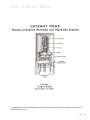
Thank you for purchasing the Musical Fidelity Nu-Vista 800 integrated amplifier.
The Nu-Vista 800 uses our tried and tested ultra-low distortion power amplifier circuitry, which has enough current
reserve to drive even the most demanding speakers with ease. The low noise and distortion, high-quality Nu-Vista
preamplifier uses valve* circuits used in our original Nu-Vista products, redesigned, to fulfil our latest practices
and expectations. This completes the integrated amplifier giving a perfect sound from a great looking full size unit.
The Nu-Vista 800 will aesthetically match with present and future Nu-Vista series products. Such a combination
will yield one of the best high-fidelity systems available at any price.
Used properly and carefully, it should give many years of outstanding musical reproduction.
Dust regularly with a soft duster or soft brush, but be careful when using cleaning or polishing agents - they may
harm the surface finish.
If there are any questions about the audio system, please consult the dealer, who is there to help and advise.
* UK English “valve” mentioned hereafter, refers to the ‘electron valve’ kind, also known as electron “tube” in
other parts of the world.
Page 2
CONTENTS
Section
Page
Safety Information
–
Mains plug (UK only), modification warning
4
General advice
–
Installation precautions
5
Installation
–
Introduction, cleaning, installation, power connections, audio
connections
6
Facilities and connections
–
Illustrations, main unit front & rear panels
7
Remote control handset
–
Operation and illustration
8
Operation
–
Starting
9
–
Volume
–
Mute
–
CD
–
AUX1/HT
–
AUX2
–
TUNER
–
Balanced
–
Illuminations
–
Wiring
11
Problems?
–
Basic fault finding
12
Specifications
–
Product specifications
13
Manual history
10
14
Item disposal information
Page 3
SAFETY INFORMATION
IMPORTANT! (U.K. only)
This unit is supplied in the U.K. with mains lead fitted with a moulded 13 amp plug. If, for any reason, it is necessary
to remove the plug, please remove the fuse holder and dispose of the plug safely, out of reach of children.
It must not be plugged into a mains outlet.
The wires in the mains lead supplied with this appliance are coloured in accordance with the following code:
Green and yellow ............................. Earth
Blue................................................ Neutral
Brown .................................................. Live
WARNING – This appliance MUST be earthed
As the colours of the wires of the mains lead of this appliance may not correspond with the coloured markings
identifying the terminals in the plug, proceed as follows:
•
The wire which is coloured green-and-yellow must be connected to the terminal in the plug which is marked
with the letter E or coloured green or green-and-yellow, or by the earth symbol:
•
The wire which is coloured brown must be connected to the terminal which is marked with the letter L or
coloured red.
•
The wire which is coloured blue must be connected to the terminal which is marked with the letter N or coloured
black.
•
If connecting to a BS1363 plug, a 13 amp fuse must be used.
WARNING:
ANY MODIFICATIONS TO THIS PRODUCT NOT EXPRESSLY APPROVED
BY MUSICAL FIDELITY WHO IS THE PARTY RESPONSIBLE FOR
STANDARDS COMPLIANCE COULD VOID THE USER'S AUTHORITY TO
OPERATE THIS EQUIPMENT.
Page 4
GENERAL ADVICE
Installation, Precautions & User Information
This new Nu-Vista 800 is designed and built to provide trouble-free performance, but as with all electronic devices
it is necessary to observe a few precautions:
•
Heed all warnings shown on the back of the product.
•
Only connect the Nu-Vista 800 to a mains outlet having the same voltage as marked at the back of the unit.
•
Always ensure that when disconnecting and reconnecting your audio equipment the mains supply is switched
off.
•
Position the mains lead and signal interconnects where they are not likely to be walked on or trapped by items
placed on them.
•
Do not use near water, or place water-filled containers on the Nu-Vista 800, for example, a flower vase or
potted plants. If water does spill inside, immediately pull out the mains plug from the wall socket and
inform your dealer, who should then check the unit before further use. Entry of liquid into the Nu-Vista
800 is dangerous, and may cause electric shock or fire hazard.
•
Do not place the unit near direct heat sources such as radiators, direct sunlight or other equipment.
•
Do not remove any covers or try to gain access to the inside. There are no internal adjustments or fuses you
can replace yourself. Refer all service work to an authorised Musical Fidelity agent.
* Note: Unauthorised opening of the equipment will invalidate any warranty claim.
•
Dust regularly with a soft cloth or soft brush but be careful when using cleaning or polishing agents - they may
harm the surface finish.
The electronics in modern hi-fi equipment is complex and may, therefore, be adversely affected or damaged by
lightning. For protection of the audio system during electrical storms, remove the mains plugs.
If after-sales service is required, to help the dealer identify the Nu-Vista 800 please quote the serial number
located on the rear panel of the unit.
Page 5
INSTALLATION
Introduction
Congratulations on the purchase of the new Nu-Vista 800 integrated amplifier. Great attention has been paid to
internal layout, isolating each circuit section to prevent possible interaction. The unit features a finely tuned and
tweaked Nu-Vista valve preamplifier, for smooth sound coupled with low noise and virtually no distortion.
The power amplifier consists of two top quality power amplifiers for the absolute best in separation and imaging.
Generously rated, they are enough to drive even the most demanding loudspeakers with ease. Low distortion and
very quiet they will deliver all music types exactly as the artist originally intended.
The resultant performance achieved by this unit is among the best in the world. It has excellent signal to noise
ratio, low distortion, wide bandwidth and dynamic range, with extraordinary resolution and fine detail.
Cleaning
Before cleaning the unit, switch off power at the mains switch and remove the mains plug from the wall socket.
Clean the cabinet and remote control unit using a moist cloth. Using solvents, white spirit or thinners is not advised,
as they could damage the surface finish.
Installation
Position the Nu-Vista 800 on a stable, horizontal surface where there is no risk of it being knocked, or subjected
to vibration such as from loudspeakers.
Important note:
During normal operation, the unit dissipates an appreciable quantity of power at all times, and it is
important that it is well ventilated. The top and bottom are perforated to allow the smooth flow of
heat through the unit. However, the unit must not be enclosed in a cabinet or placed where the
ventilation holes are impeded as this could result in excessive heat build-up.
The Nu-Vista 800 must be protected from humidity – if the unit is moved from a cold place to a warm
room, leave the unit for an hour or so to allow sufficient time for the moisture to evaporate.
Power Connections
The Nu-Vista 800 is supplied with a standard IEC mains cable which plugs into the IEC socket at the back of the
unit (see page 7). When plugged in and mains supply is present the orange STDBY LED will light.
Audio Connections
RCA Inputs: Connect all RCA single-ended sources to relevant analogue inputs (see page 7 for more
information). Use good quality fully connected (signal and ground) coaxial phono cables for all RCA signal
connections. Take care with positioning all input leads, try to ensure that they are well shielded and kept as far
away from mains and speaker leads as possible.
XLR Balanced inputs: Connect source balanced outputs to Nu-Vista 800 balanced inputs using good quality
XLR balanced leads. Recommended lead wiring is shown on P.7. Note some products simply connect “cold” input
pin 3 to ground. This does no harm to unit, but may result in an audible reduction in signal level from this input
and a slightly worse signal to noise ratio.
Speaker Outputs: Connect loudspeakers to the terminals on the back panel marked as LEFT and RIGHT
SPEAKER outputs. See “WIRING” P.11 for more details.
LINE output sockets allow loop through of analogue signals for example, to pass on to a recorder or monitor. It is
also the ideal output to connect headphone amps into (headphone amplifier will require its own volume control to
allow listening level adjustment). This output is the currently selected source but level is not changed by the front
panel volume control.
PRE-OUT output sockets allow analogue signals controlled by the volume, to pass on to, for example, an external
power amplifier. This is useful for bi-amping or active “subwoofer” connection where volume out needs to be
controlled by the Nu-Vista 800 front panel volume knob.
Page 6
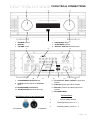
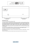
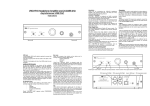
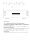
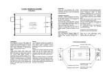
FACILITIES & CONNECTIONS
1
1
2
3
2
4
SOURCE selector
DISPLAY
VOLUME control
7
3
5
4
5
6
8
10
11
7
LOUDSPEAKER OUTPUTS right
8
HT/AUX function selector for AUX1/HT
input
12
6
ON/STANDBY Button
IR RECEIVER window
DISPLAY AND LED functions button
9
13
14
11 CD, AUX1/HT, AUX2, TUNER line input RCA
sockets
12 LINE OUT (fixed) output RCA sockets
9 LOUDSPEAKER OUTPUTS left
13 PRE OUT (volume controlled) output RCA
sockets
10 XLR BALANCED inputs left and right
14 IEC MAINS INPUT
XLR Balanced input and output lead
connections:
Pin functions:
1
Ground (cable shield)
2
Normal polarity ("hot" or “+”)
3
Inverted polarity ("cold" or “-“)
(for reference, no XLR signal leads supplied)
Page 7
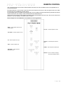
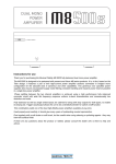
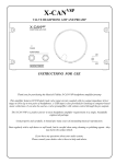
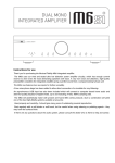
REMOTE CONTROL
The universal remote control shown below enables functions from this and related units to be operated from a
convenient distance.
Equivalent buttons on the remote control have the same functions as those on the front panel of the unit. Other
functions are only available by remote control.
As the handset uses an invisible infra-red light beam, the front edge must be pointed directly towards the receiver
window at the front of the player, without visual obstruction between them.
If the range of the remote control greatly decreases, replace the batteries with new ones. Do not mix old and new
batteries – two are required, size AAA, LR03 or SUM-4.
Please dispose of used batteries in accordance to local regulations.
MUTE – mutes speaker outputs (until
pressed again).
VOL UP – increases amplifier volume
VOL DOWN – reduces amplifier volume
CD – selects amplifier CD input
AUX1/HT – selects amplifier AUX1/HT
input
AUX2 – selects amplifier input
TUNER – selects amplifier TUNER input
BALANCED – selects amplifier
BALANCED input
DISPLAY – dims or switches off display
and other illumination effects
Page 8
OPERATION
Starting
Once all connections are made, switch on the unit, using the POWER button front of the unit. The display will light
up and base LEDs (under front panel) will show RED. This means the speaker outputs are muted, and will remain
in this state for about 12 seconds, so no sound will be heard from the speakers. Once the delay is up, the base
LEDs go green, indicating unit is ready for use, and any source material selected and playing will be heard through
the speakers.
For the first 15 mins or so, the Nu-Vista valves are still warming up, and the valve illumination will be yellow in
colour. After approx.. 20 mins the valves will have reached full thermal equilibrium and are at their best
performance, which is indicated by the illumination turning green.
Volume
.
42.0
CD
The volume should be adjusted for normal listening levels. This is done by turning the volume up/down knob on
the front panel.
Adjusting the volume can also be achieved by pressing the volume up/down buttons on the remote control handset
(see page 8).
Mute (Remote Control only)
The sound from the speakers may be muted by use of the MUTE button on the remote (see page 8).
Press once, and LEDs under the unit and illumination around the valves will light RED indicating muted state. No
sound will be heard from the speakers.
To return to listening; simply press the MUTE button again so LEDs are no longer red.
CD
.
60.0
CD
To use the CD input, connect CD player outputs to the CD input RCA sockets (see page 7).
Select CD input by rotating the source select control so CD is displayed.
Pressing the corresponding button on the remote handset has the same effect (see page 8).
AUXILIARY 1/HT
60.0
. AUXILIARY 1
To use the AUX1/HT input as a standard input, move the AUX/HT switch on the back panel to the AUX position.
Connect source outputs to the AUX1 input RCA sockets (see page 7).
Select AUX1/HT input by rotating the source select control so AUXILIARY 1 is displayed.
Pressing the corresponding button on the remote handset has the same effect (see page 8).
60.0
. HOME THEATRE
To use the AUX1/HT input as a Home Theatre input, move the AUX/HT switch to the HT position. This input is
now unaffected by the volume control, allowing volume control on an external Home Theatre processor to be used
directly. Connect home theatre or other source outputs to the AUX1/HT input RCA sockets (see page 7). Select
AUX 1/HT input by rotating the source select control so HOME THEATRE is displayed.
IMPORTANT: Take great care when using the input in HT mode. Ensure that the volume control is turned right
down on the HT processor when first setting up. The HT mode is designed for sources which require their own
volume control to be used. Connecting sources in HT mode with no volume control could result in damage to
hearing and/or speakers due to uncontrolled loud sounds.
AUX 2
60.0
. AUXILIARY 2
To use the AUX 2 input, connect source outputs to the AUX 2 input RCA sockets (see page 7).
Select AUX 2 input by rotating the source select control so AUXILLIARY 2 is displayed.
Pressing the corresponding button on the remote handset has the same effect (see page 8).
TUNER
.
60.0
TUNER
To use the tuner input, connect tuner outputs to the TUNER input RCA sockets (see page 7).
Select TUNER input by rotating the source select control so TUNER is displayed.
Pressing the corresponding button on the remote handset has the same effect (see page 8).
Page 9
OPERATION
BALANCED
.
60.0
BALANCED
To use the BALANCED input, connect source balanced outputs to the BALANCED input sockets (see page 7).
Select BALANCED input by rotating the source select control so BALANCED is displayed.
Pressing the corresponding button on the remote handset has the same effect (see page 8).
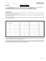
ILLUMINATIONS
When used in darker environments, for example listening or home theatre rooms. It is possible to switch off
selected features to minimise distraction.
The illumination features (excluding the power/standby LEDs) can be switched on or off by pressing the DISPLAY
button on the front panel.
There is also a corresponding button on the remote control. To cover all options, all 8 permutations are available
for use, tabulated below.
STEP
DISPLAY
BASE ILLUMINATION
VALVE ILLUMINATION
1 (default)
ON
ON
ON
2
OFF
ON
ON
3
ON
OFF
ON
4
OFF
OFF
ON
5
ON
ON
OFF
6
OFF
ON
OFF
7
ON
OFF
OFF
8
OFF
OFF
OFF
To select the desired step, simply press the DISPLAY button on the front panel or remote until the required step
is reached. After step 8, the unit reverts back to step 1.
Please note, switching off the unit will store the current step. When next switched on, the remembered setting
will be overridden temporarily until after the initial 12 second mute delay. Once the delay is up, the unit will revert
to normal operation but with the step setting as previously selected.
P a g e 10
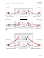
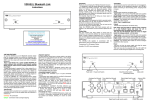
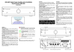
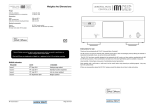
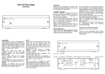
WIRING
Simple speaker lead wiring
Bass/treble terminal links in
Bass/treble terminal links in
(source and mains leads omitted for clarity)
Speaker lead bi-wiring
Bass/treble terminal links removed
(source and mains leads omitted for clarity)
Bass/treble terminal links removed
Speaker bi-amping (requires additional power amplifier)
Bass/treble terminal links removed
(source and mains leads omitted for clarity)
Bass/treble terminal links removed
P a g e 11
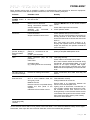
PROBLEMS?
Basic problem-solving with an amplifier is similar to troubleshooting other electrical or electronic equipment.
Always check the most obvious possible causes first, such as the following examples:
Problem
Probable Cause
Remedy
No power when
POWER button is
pressed.
Mains power plug is not fully inserted
into rear socket.
Plug in securely.
No sound
Mute function is still active.
Wrong connections between input
sources and the unit
Speakers
not
connected,
or
incorrectly wired
Press the MUTE button on the remote control to
cancel.
Check audio input lead connections.
Check speaker cables.
Sound cut
Loose connection
Output overload or short circuit
Check speaker and input connections.
Switch unit off. Check speaker connections for
shorting strands or wires. When all has been
double-checked reduce volume and switch unit
back on.
N.B. Take great care when bi-wiring or biamping that speaker bass and treble linking
straps are removed; see speaker manual for
more information.
Sound is not
precise, lacking in
bass and stereo
image.
Speakers are connected out of
phase, i.e., connections to one
speaker
(+ and –) are reversed.
Ensure speakers are connected with same
polarity at amplifier and speaker ends.
Hum.
Audio connector plug not fully
pushed in
Cable Fault
Unsuitable cable
(e.g. cable grounds not connected)
Insert plug securely.
Check cable is connected at both ends.
N.B. Some esoteric cables have internal wiring
intentionally disconnected/modified. For best
results on all inputs analogue AND digital,
please use good quality screened coax; signal
and screens both separately connected at both
ends.
No audio output, or
too low level output.
Incorrect or missing connections
Check connections and make sure they are
secure.
Remote control
does not work.
Amplifier’s POWER off.
One or more batteries fitted the
wrong way round.
Batteries are flat.
Remote control is not pointed directly
towards the front panel of the
amplifier.
Interference from another source.
Switch on.
Insert batteries correctly.
Change batteries for a new set.
Ensure there is no obstruction between the
remote control and amplifier front.
Lighting such as fluorescent, incandescent, or
even sunlight contains large amounts of infrared radiation. Ensure such sources are not
shining directly on the infra-red window as this
could swamp the signal from the remote control.
Also check the system and any other nearby
remotes for stuck buttons.
Remote control
range has greatly
reduced
Batteries are running out
Change batteries for a new set.
If none of these actions affect a cure, please contact the dealer, or an authorised Musical Fidelity service agent.
Remember; never open the case of the Nu-Vista 800, as this will invalidate the guarantee.
P a g e 12
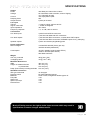
SPECIFICATIONS
Output
Power
Voltage
Current
Damping factor
Output devices
330 Watts per channel into 8 Ohms
52 Volts RMS, 20Hz to 20 kHz; onset of clipping
147 Volts peak to peak
120 Amps peak to peak
200
5 pairs per channel
Line input
THD+N
Signal / noise ratio
Input impedance
Frequency response
< 0.005 % typical, 20Hz to 20 kHz
> 107dB ‘A’-weighted
40 k Ohms
+ 0, –0.1dB, 10Hz to 30 kHz
Connections
Line level inputs
4 pairs line level RCA connectors
1 pair line level balanced XLR connectors
Line level outputs
1 pair line level RCA connectors, constant level LINE outputs
1 pair line level RCA connectors, PREAMP outputs for e.g. biamping
Speaker outputs
2 pairs 4mm banana plug/binding posts
Power requirement
Mains voltages
Consumption
115/230VAC 50/60Hz (factory pre-set)
100VAC 50/60Hz (alternative)
<0.5W in standby mode (orange LED lit)
130W on and idle (blue LED lit)
900 Watts maximum
Weight
Unit only, unboxed
in shipping carton
39 kg (85 4/5 lbs)
47 kg (103 2/5 lbs)
Maximum Dimensions
Wide
Height on standard flat feet
on pointed feet
Deep (front to back) including terminals
483 mm (19”)
187 mm (7⅓”)
212 mm (8⅓”)
510 mm (15¾”)
Standard accessories
IEC type mains lead
Remote control
Batteries
Felt pads
Spike Foot
Spike Foot Cups
Remote Feet
10-Amp type
Nu-Vista Integrated remote
LR03 or AAA, manganese alkaline type 2 off
4 off
4 off
4 off
4 off
Musical Fidelity reserves the right to make improvements which may result in
specification or feature changes without notice.
P a g e 13
MANUAL HISTORY
DISPOSAL INFORMATION
RELEASE
Nu-Vista 800 Integrated
DATE
th
16 July 2014
CHANGES
1st issue
DISPOSAL
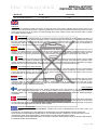
The crossed out wheeled bin label that appears on the back panel of the product indicates that the product must not be
disposed of as normal household waste. To prevent possible harm to the environment please separate the product from other
waste to ensure that it can be recycled in an environmentally safe manner. Please contact local government office or retailer
for available collection facilities.
DISPOSITION
La poubelle sur roulettes barrées X, qui apparaît en logo sur le panneau arrière du produit, indique que celui-ci ne
doit pas être traité comme un déchet domestique commun. Afin de protéger l'environnement, ce produit électronique devra
être géré séparément et donc recyclé selon les nouvelles normes Européennes Rohs concernant les déchets d'appareils
électroniques. Prière de contacter les services concernés gouvernementaux ou votre point de vente pour l'élimination et
l'enlèvement de déchets électroniques équipés de composants électroniques.
DISPOSAL
La etiqueta cruzada hacia fuera del compartimiento que aparece en el panel trasero del producto indica que el
producto no se debe reciclarse como basura normal de la casa. Para prevenir daños posible al ambiente separe por favor el
producto de otra basura para asegurarse de que puede ser reciclada de una manera ambientalmente segura. Entre en
contacto por favor a su oficina gubernamental local o a su minorista para las instalaciones disponibles de la colección.
RIFIUTI
L'etichetta del cassonetto barrato riportato sul retro dell'apparecchio indica che il prodotto non deve essere smaltito
tramite la procedura normale di smaltimento dei rifiuti domestici. Per evitare eventuali danni all'ambiente, separare questo
prodotto da altri rifiuti domestici in modo che possa venire riciclato in base alle procedure di rispetto ambientale. Per maggiori
dettagli sulle aree di raccolta disponibili, contattate l'ufficio govenativo locale od il rivenditore del prodotto.
FACHGERECHTE ENTSORGUNG:
Das auf der Geräterückseite angebrachte Label deutet darauf hin, dass das Produkt nicht mit konventionellem
Hauskehricht entsorgt werden darf. Um Schäden und Verschmutzungen an Umwelt und Mensch zu vermeiden, muss das
Produkt fachgerecht entsorgt und von anderem Abfall getrennt werden. Wenden Sie sich bei Fragen hierzu an Ihren
Fachhändler oder an eine öffentliche Informationsstelle.
AFVAL
Het label op de achterzijde van dit apparaat, een afvalbak op wielen met een kruis doorgehaald, geeft aan dat dit
apparaat niet samen met gewoon huishoudafval mag worden weggegooid. Om mogelijke schade aan onze leefomgeving te
voorkomen dient dit apparaat, gescheiden van gewoon huishoudelijk afval, te worden afgevoerd zodat het op een
milieuvriendelijke manier kan worden gerecycled. Neem voor beschikbare inzamelplaatsen contact op met uw gemeentelijke
reinigingsdienst of met uw elektronica leverancier.
HÄVITTÄMINEN
Yliruksattua jäteastiaa kuvaava tarra tuotteen takalevyssä kertoo, että tuotetta ei saa käsitellä normaalina
talousjätteenä. Ympäristön suojelemiseksi on tuote pidettävä erillään muusta jätteestä ja se on kierrätettävä ekologisesti
kestävällä tavalla. Ota yhteyttä laitteen myyjään tai Pirkanmaan Ympäristökeskukseen lähimmän kierrätyskeskuksen
löytämiseksi.
AFSKAFNING
Logoet med en skraldespand med kryds over på bagsiden af apparatet indikerer at dette produkt ikke må kasseres
som normal husholdningsaffald. For at forebygge mulig skade på miljøet, bedes De separere dette produkt fra andet affald,
og sikre at det bliver genbrugt på en miljørigtig måde. Kontakt venligst de lokale myndigheder eller din forhandler for oplysning
om nærmeste tilgængelige opsamlingssted for elektronikaffald.
∆ΙΑ∆ΙΚΑΣΙΑ ΑΠΟΡΡΙΨΗΣ
ΤΟ ΣΗΜΑ ΜΕ ΤΟΝ ∆ΙΑΓΕΓΡΑΜΜΕΝΟ ΤΡΟΧΗΛΑΤΟ ΚΑ∆Ο ΑΠΟΡΡΙΜΑΤΩΝ ΣΤΗΝ ΠΙΣΩ ΟΨΗ ΤΟΥ
ΜΗΧΑΝΗΜΑΤΟΣ
∆ΗΛΩΝΕΙ ΟΤΙ ΤΟ ΠΡΟΙΟΝ ΑΥΤΟ ∆ΕΝ ΠΡΕΠΕΙ ΝΑ ∆ΙΑΧΕΙΡΙΣΘΕΙ ΣΑΝ ΣΥΝΗΘΙΣΜΕΝΟ ΟΙΚΙΑΚΟ ΑΠΟΒΛΗΤΟ.
ΠΡΟΣ ΑΠΟΦΥΓΗ ΕΝ∆ΕΧΟΜΕΝΗΣ ΕΠΙΒΑΡΥΝΣΗΣ ΤΟΥ ΠΕΡΙΒΑΛΛΟΝΤΟΣ, ΞΕΧΩΡΙΣΤΕ ΤΟ ΠΡΟΙΟΝ ΑΠΟ ΤΑ ΑΛΛΑ
ΑΠΟΡΡΙΜΑΤΑ ΩΣΤΕ ΝΑ ΕΞΑΣΦΑΛΙΣΘΕΙ Η ΑΝΑΚΥΚΛΩΣΗ ΤΟΥ ΜΕ ΤΟΝ ΠΡΕΠΟΝΤΑ ΤΡΟΠΟ.
ΠΑΡΑΚΑΛΟΥΜΕ ΝΑ ΕΠΙΚΟΙΝΩΝΗΣΕΤΕ ΜΕ ΤΗΝ ΤΟΠΙΚΗ ΥΠΗΡΕΣΙΑ ΑΝΑΚΥΚΛΩΣΗΣ Η ΜΕ ΤΟ ΚΑΤΑΣΤΗΜΑ ΑΓΟΡΑΣ
ΓΙΑ ΠΕΡΙΣΣΟΤΕΡΕΣ ΛΕΠΤΟΜΕΡΕΙΕΣ.
P a g e 14