1
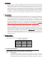
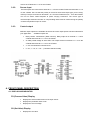
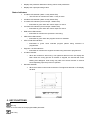
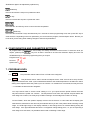
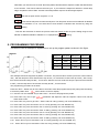
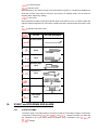
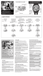
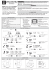
VT30 SERIES FUZZY ENHANCED PROGRAMMABLE CONTROLLERS INSTRUCTION MANUAL (VERSION 6.0) CONTENTS .................................................................................................................................................................................... 1. OVERVIEW......................................................................................................................................................................... 2 2. IN A HURRY? ..................................................................................................................................................................... 2 3. INSTALLATION ................................................................................................................................................................... 2 3.1. PANEL MOUNTING ............................................................................................................................................................ 2 3.2. CONNECTION AND WIRING ............................................................................................................................................... 2 4. FRONT PANEL DESCRIPTION .............................................................................................................................................. 3 4.1. DISPLAY AND INDICATOR ................................................................................................................................................... 3 5. KEY FUNCTIONS ................................................................................................................................................................ 4 7. PROGRAM LEVEL ............................................................................................................................................................... 5 8. PROGRAMMING PROCEDURE ........................................................................................................................................... 6 10. USER LEVEL ....................................................................................................................................................................... 7 11. SOFT LEVEL ........................................................................................................................................................................ 9 12. PID LEVEL .......................................................................................................................................................................... 9 13. OPTION LEVEL ................................................................................................................................................................. 10 14. OPERATION ..................................................................................................................................................................... 11 14.1. AUTO TUNE ..................................................................................................................................................................... 11 14.2. TUNING THE CONTROLLER MANUALLY ............................................................................................................................ 12 14.1. MANUAL CONTROL ......................................................................................................................................................... 12 15. ALARM ............................................................................................................................................................................ 12 15.1. ALARM FUNCTION........................................................................................................................................................... 12 15.1. ALARM MODES ............................................................................................................................................................... 12 16. EVENT AND PROGRAM END ALARM ................................................................................................................................ 13 16.1. EVENT ALARMS ............................................................................................................................................................... 13 16.2. PROGRAM END ALARM ................................................................................................................................................... 14 16.3. REMOTE RUN OPTION ..................................................................................................................................................... 14 16.4. POWER FAILURE .............................................................................................................................................................. 14 16.5. SPECIFICATIONS ............................................................................................................................................................... 14 17. ERROR MESSAGE AND TROUBLESHOOTING .................................................................................................................... 15 1 1. OVERVIEW The VT30 Series is our "Pattern Programmable" 16 step ramp and soak FUZZY enhanced three term (PID) Dual Display, self-tuning controller, designed for use in applications where "control accuracy" and "Profile Control" is required. You can have one 16 step program (each step includes start, ramp and soak phases) or choose to have two 8 step programs stored for different applications. It comes standard with 2 alarms that can be used in a variety of alarm modes or used as “event” alarms linked to end of steps in the program. This controller can be networked on a Modbus RS485 network or used in a remote run configuration. All in all it is a very versatile “pattern programmable controller” at a very attractive price. 2. IN A HURRY? The VT30 series controllers require a bit more reading than the rest of our controllers; understandably so as you require that they perform reasonably complex “pattern control”, notwithstanding this it is still a reasonably simple controller to setup and program and should not be difficult. We suggest that you first install the controller and turn it on after checking that the inputs and outputs are correctly wired and that the temperature displayed in the “PV” display is roughly what you would expect it to be and that the heating elements actually get hot when the “c1” output light on the controller display is on. Next and before you start “pattern” control read item 9.3 and 9.4. This is very important. In order to program and get going you will now need to read the following sections … ”Front panel description”, “Key functions”, “Configuration and Parameter Settings…Program Level….Programming Procedure …. Setting up and starting pattern control.” Then under the “Operation” section read the “Auto Tune” section. If you wish to use event alarms etc the rest of the Operation section must be read. If you need more assistance please do not hesitate to contact Vertex by e-mail [email protected] and for more in-depth assistance draw a timeline graph showing each output and it‟s status during sections of the pattern and what you need to controller to achieve and send it to us and we will gladly offer as much advice and assistance as we can. 3. INSTALLATION 3.1. PANEL MOUNTING Prepare a panel cutout. The cutout required is as show in table 1-1. Table 1-1 Panel Cutout Model High Width VT4830 45mm﹢0.5 45mm﹢0.5 VT4930 45mm﹢0.5 92mm﹢0.5 VT7230 68mm﹢0.5 68mm﹢0.5 VT9630 92mm﹢0.5 92mm﹢0.5 3.2. CONNECTION AND WIRING BEFORE WIRING BE SURE TO CHECK THE LABLE FOR CORRECT MODEL AND OPTIONS. Please check on the side of the controller for correct wiring 3.2.1. Power input The controller can be operated on 90~264 VDC or VAC 50/60 Hz or 24VDC (18~32 VDC optional). The controller should be protected by a suitable fuse or circuit breaker. The power (heater) circuit should be protected by a separate circuit breaker. Power goes on terminals 19 2 +20 for the VT9630 and 1 + 2 for the VT4830. 3.2.2. Sensor input Thermocouples are connected to terminals 7 + 8 for the model VT4830 and terminals 9 + 10 for the VT9630. Be sure that the polarity is correct for the thermocouple type you are using. RTD‟s (PT100) is connected on terminals 7, 8 + 9 for the VT4830 and 8, 9 + 10 for the VT9630. Do not run sensor cables adjacent to power carrying conductors. The correct type of thermocouple extension lead wire or compensating cable must be used ensuring the polarity of thermocouple/linear input is correct. 3.2.3. Control output Different output options are available. Be sure that correct output option has been selected for your application. Available outputs are: Relay contact. 10A/240VAC. (Most common) Relay output is on terminal 17 + 18 for VT9630 and terminals 11 + 12 on the V4830. 24 VDC pulsed voltage to drive SSR. This output will be on terminals 17 + 18 on the VT9630 and terminals 11 + 12 on the VT4830. 4 ~ 20 mA. Maximum load 600 ohms 0 ~ 5V, 1 ~ 5V, 0 ~ 10V…..( Resistive 600 ohms Min) 4. FRONT PANEL DESCRIPTION 4.1. DISPLAY AND INDICATOR PV (Process Value) Display Displays the actual measurement of the input sensor. Displays the parameter index code. Displays the error message. SV (Set Value) Display Displays the set value. 3 Displays the parameter data when viewing various level parameters. Displays the output percentage value. Status indicators A1 status LED indicator (Alarm 1 relay status LED) o This LED is lit in red when the alarm 1 relay is active. A2 status LED indicator (Alarm 2 relay status LED) C1 status LED indicator (Control output 1 status LED) o C2 status LED indicator (Control output 2 status LED) o Illuminates in red when the operation is executing. PRO status LED indicator. o Illuminates in green when the control output 2 is active. RUN status LED indicator. o Illuminates in green when the control output 1 is active. Illuminates in green when the program function is available. PTN1 PTN2 LED indicators. o Illuminates in green when selected program pattern being executed or programmed. Segment 1~8 LED indicators. o Illuminates in red when the segment number being executed or programmed. AT status indicator o When the controller is auto tuning. The rightmost decimal on the PV display will blink. When the tuning process is finished or stopped, the decimal will cease blinking and disappear. Auto tuning may take from several minutes to several hours depending upon the process in question. MA status indicator o When the manual control mode is selected. The rightmost decimal on SV display will blink. 5. KEY FUNCTIONS SET key Press once to access the next programmable parameter. SHIFT key 4 Shift/selects digits to be adjusted by up/down key. DOWN key Press to decrease the set point or parameter value. UP key Press to increase the set point or parameter value. Press the SET and UP keys once to return the normal operation. LEVEL key Press the SET and SHIFT keys simultaneously for 5 seconds to select programming level, then press SET key to enter the level. Depending on the lock parameter, you can access the program, PID and Option levels. Be sure you know what you are doing when making changes to these level parameters. 6. CONFIGURATION AND PARAMETER SETTINGS All programmable parameters are user friendly and clearly structured in three levels. To select the level you require, please press keys for at least 5 seconds to access level selection display and now use UP/DOWN keys to select the programming level you require. Program level. ( Pid level. ( Option level. ( ) ) ) 7. PROGRAM LEVEL 7.1. 7.2. This parameter selects either PTN1 or PTN2 to be configured. This parameter sets a “band” around the setpoint at the “soak” level of each “ramp & soak” stage, such that the next “soak” cycle is inhibited and waits for the actual temperature to be within the “band” setting of the setpoint before the profile cycle can continue. On models from V4 onwards, this may be set to “-1” to disable the band function altogether. You may however wish to set this “band” setting to “0” if you require that the profile reaches the exact set-point before the profile can continue. The temperature must reach the required set-point before the soak stage can continue, but it may drop off after reaching it and the stage will continue on timing. On the VT9630, which has “pattern” displays such as “Ptn1 & Ptn2 etc” in a line under the SV display (The 4830 which is restricted for size does not) that indicate where you are in the pattern while executing a ramp stage, the PTN1 light stage on the display will flash, it will change and be on without flashing during the soak stage. If the light still flashes but there is no apparent change taking place, i.e. you are expecting a soak stage to be executed, it is possible that the band is inhibiting a soak stage. 5 Note that if you choose to use a “band” the whole pattern will wait until the setpoint is within that band before it can continue. One area to watch is the end cycle. If you reduce the setpoint to ambient in a final ramp stage, the pattern cannot “END” until the actual temperature drops to the final target setpoint. : Set the set point of each segment. n=1~8. : This sets the ramp time to reach the set point. The ramp time can be set from 00h00m to 99h59m or 00m00s to 99m59s. n=1~8. You select Hour‟s and minutes or Minutes and seconds by using the setting. : This sets the soak time for which the process value will remain at the set point. Setting range is from 00h00m to 99h59m 00m00s to 99m59s. n=1~8.(Depend on setting) 8. PROGRAMMING PROCEDURE This section uses an example to explain how to set up the program pattern as show in the figure. Segment Set point Ramp time Soak time 1 100℃ 30min. 30min 2 300℃ 30min. 1hour 3 200℃ 30min 30min 4 - End - This example uses three segments in pattern 1 as shown. The process value will rise up from the current value to 100℃ with the ramp time of 30 minutes and stay at 100℃ for 30 minutes. It then rises up to 300℃ with a ramp time of 30 minutes and stays at 300℃ for one hour. After the one hour soak time is up the process will cool down to 200℃ with the ramp time of 30 minutes and stay at 200℃ for 30 minutes. The programming procedure is as follow. Press the “SET” + “BACK” key for more than 4 seconds to enter the program level (ProG). Now press the set key to reach the pattern level. will be shown on the PV display. 8.1. Use the “UP” and “DOWN” key to select “Ptn1” where we will program the profile. 8.2. Press “SET” key once to get “ ” parameter and adjust the value as required. If don‟t know, set the band value to zero. 8.3. Press “SET” key once to get “SP1”. Set the value to 100 by pressing “UP” and “DOWN” key. 8.4. Press “SET” key once and set the “rt1” to 0.30 by pressing “UP” and “DOWN” key. 8.5. Press “SET” key once and set the “St1” to 0.30 by pressing “UP” and “DOWN” key. 8.6. Press “SET” key once and set the “SP2” to 300 by pressing “UP” and “DOWN” key. 8.7. Press “SET” key once and set the “rt2” to 0.30 by pressing “UP” and “DOWN” key. 8.8. Press “SET” key once and set the “St2” to 1.00 by pressing “UP” and “DOWN” key. 8.9. Press “SET” key once and set the “SP3” to 200 by pressing “UP” and “DOWN” key. 8.10. Press “SET” key once and set the “rt3” to 0.30 by pressing “UP” and “DOWN” key. 8.11. Press “SET” key once and set the “St3” to 0.30 by pressing “UP” and “DOWN” key. 6 8.12. To terminate the pattern 1, Press “SET” key twice and set the “rt4” to “end” by using the “down” key. 9. SETTING UP AND STARTING PATTERN CONTROL 9.1. First decide on the various points to be used in your pattern as described above and then set them as explained in the example above. 9.2. Decide if you require any “alarms” or “event alarms” to be used in the program and set them using alarm function and setpoint settings to be found in the “Option, PID and User levels. 9.3. You must then also check the following points or settings before starting control. 9.4. You should first force the controller to do a self-tune procedure of the PID parameters before initiating Pattern Control. This will set the “control PID parameters” to best suit your application. To do this set the parameter (to be found in the User Level) to and the “run” parameter also in the user level to run. Now set the PV setpoint to a suitable temperature at which it will control for the most time during the pattern. Now once the controller has reached that temperature initiate a self-tune process as described in the section and let it complete its parameter tuning. During this operation the “dot” led in the bottom right hand corner “At” will flash. Having done that and verifying that the controller is functioning well at that setpoint you may start using it in the pattern mode. 9.5. You must now set the parameter “level as in to “on” using the desired program option to be found in the “user etc. The “Pro” light on the controller will now be lit. 9.6. Now set the starting setpoint (SV) to the temperature from which the pattern must ramp, up to the “SP1” as set above. (This will usually be the ambient or the current PV Reading if the oven is already warm) The cycle will start from this setting and ramp to the “SP1” setting at the ramp rate set in “rt1” . 9.7. Now select the go to the profile setting you wish to execute as in Pattern 1 or Pattern 2 set above and then parameter and set it to “run” 9.8. The controller will execute the pattern as set and end as instructed. 9.9. You may choose to have an external start (remote run) input that will start one or more controllers at the same time, using the remote run input (potential free input) on the rear terminals. This option is free with all models except the 48 x 48 size, which requires a modification. Should you require this option it must be specified (for all models) at the time of ordering. Since this input uses the same terminals as the second output on the 48 x 48 size you cannot have a second output and a remote run option together on the 48 x 48 size. 9.10. This input will work just like the run/stop option available from the keypad. When this contact is made the program will over-ride the keypad “run” status and always run. When it is opened the program will revert to the status of the keypad setting which would normally be stop and will reset to the beginning of the cycle for the next start. The “keypad” status may be set to stop, hold or run, in which case the controller will behave accordingly. 10. USER LEVEL The following parameters are listed in a default sequence. However any unused parameter can be removed and the display sequence is configurable to simplify the operation. 1. : Set point value of control. 2. : Alarm 1 set point value. 7 3. : Alarm 2 set point value. 4. : Auto tune. Used to set Pb,ti,td parameters value automatically by auto tuning. 5. : Auto tuning is off. 6. : This is the most common “auto tuning” procedure. It is done at the setpoint. 7. : This “auto tuning” procedure is done at a lower setpoint defined by SV-10%FS . It would be used if it is critical that during the auto tuning process the temperature does not go higher than the set point set. 8. Note: The auto tuning process will force the controller to take the temperature up and down by a fixed amount around the setpoint twice and then use the measured reaction results to calculate and set the Pb,ti,td parameters. 9. Note: Do not make any changes to the controller or process while doing this procedure as it will cause errors in the tuning and the controller may not work as well as it should. 10. : Hand (manual) control mode. Enabling this means that the controller output will be set manually using the up and down buttons. The controller will not make any corrections should the temperature overshoot, and if left unattended may cause damage to the machine or process. Once set to hand, the next parameter 11. : Disables the manual mode 12. : Enables the manual mode. 13. 14. is used to set the percentage output required. : Output percentage. Adjustable when “Hand” is set to “YES” . : This parameter controls the control status and mode of the control and alarm outputs, both when the controller is being used as a conventional unit or “pattern” controller. 15. : Actives the control output and runs the program. 16. : Turns the control output and alarms off and stops the program. 17. : Interrupts and freezes the “pattern cycle” at the point at which it is set to hold, but allows control to continue at that setpoint. 18. : This parameter selects the program pattern to be executed and dictates how the controller will behave once the cycle is completed allowing you to choose either the end, loop or hold options. 19. : Selecting this turns the program off allowing the controller to act as a normal controller. 20. : Selecting this option means that the program “pattern 1” who‟s segment parameters have been set as in the example above, will be executed and the control output will be turned off after all the segments in the pattern have being executed. 21. : Selecting this option means that the program “pattern 2” who‟s segment parameters have been set as in the example above, will be executed and the control output will be turned off after all the segments in the pattern have being executed. 22. : Selecting this option means that the program pattern 1 and pattern 2 (each having 8 segments) are linked together to be executed and the control output will be turned off after all the segments in the pattern have being executed. 23. : Selecting this option means that the program “pattern 1” will be executed and the controller will continue to control at the last setpoint of the pattern once the pattern has completed. 24. : Selecting this option means that the program “pattern 2” will be executed and the controller will continue to control at the last setpoint of the pattern once the pattern has completed. 25. : Selecting this option means that the program pattern 1 and pattern 2 are linked together to be executed and the controller will continue to control at the last setpoint of the pattern 2 once the linked pattern has completed. 26. : Selecting this option means that program “pattern 1” will loop back on itself on completion and be executed repeatedly. 8 27. : Selecting this option means that program “pattern 2” will loop back on itself on completion and be executed repeatedly 28. : Selecting this option means that pattern 1 and pattern 2 are linked together and will loop back on itself on completion and be executed repeatedly. 11. SOFT LEVEL : The ramp can be used separately from the “Soft Start” or in conjunction with as you please. With the Ramp value set to 0 the ramp is disabled. When a value has been set in ℃/min each time a setpoint change is made the setpoint will ramp at the set rate from the original value to the new setpoint value. This can be set between the ranges of 0 ~ 9999 ℃/min (0.0 – 999.9) : This is the temperature setpoint below which at startup, the output will be limited to the % value set in the “out” parameter below. This value can be set anywhere between the LoLt - HiLt values of the range. :Output percentage value to which the output will be limited at startup until the temperature has reached the S.SP setpoint above at which the output will revert to full PID regulation. 12. PID LEVEL The following parameters are listed in a default sequence. However any unused parameter can be removed and the display sequence is configurable to simplify the operation. 1. : Proportional band value. Setting range from 0.0 to 300.0 % of controller„s Span. set to 0.0 for on/off control action. This value is automatically calculated by activating the auto tune. If desired, the user can later adjust the value to better suit the application. 2. : Integral (reset) time. This value is automatically calculated by activating the Auto tune function. If desired, the user can later adjust this parameter to better suit the application. When PB=0.0, this parameter will be not available. When set to zero, Pb & td ≠0 for PD control. 3. : Derivative (rate) time. This value is automatically calculated by activating the Auto tune function. If desired, the user can later adjust this parameter to better suit the application. When PB=0.0, this parameter will be not available. When set to zero, Pb & td ≠ 0 for PI control. 4. : Cycle time of control output 1. Setting range is from 0 to 100 seconds. Set to 1 for pulsed voltage output (SSR), set to 0 for 4 ~ 20 mA analog output and set to 15 sec‟s for relay or contactors. The longer this time is set, the less responsive the controller will be to process changes and the less accurate the control will be. 5. : Proportional band value for secondary control output (cooling). Set 0.0 for ON/OFF. 6. : Integral time for secondary control output. When PB=0.0, this parameter will be not available. When set to zero, Pb & td ≠ 0 for PD control. 7. : Derivative time for secondary control output. When Pb=0.0, this parameter will be not available. When set to zero, Pb & ti ≠ 0 for PI control. 8. : Cycle time of secondary control output. 9. / : Hysteresis for on/off control on output 1and output 2. Users can create a dead band region from 0.0 to 200.0. 9 10. / : Hysteresis for alarm 1 and alarm 2.the setting range is 0.0 to 200.0. 11. : Dead band value. Setting range is from -100.0 to 100.0. This defines the area in which output 1 and output 2 are both active (negative value) or the area in which output 1 and output 2 are both inactive (positive value). : Set point offset. Setting range is from -100.0 to 100.0 or –1000 to 1000. This value will be 12. added to SV to perform control. It mainly used to eliminate offset error during P control. : Process value offset. Setting range from -100.0 to 200.0 or –1000 to 2000 permits the user to 13. offset the PV indication from the actual PV. 14. : Parameter lock. This security feature locks out selected levels or single parameters prohibiting tampering and inadvertent programming changes. Table 3-1 Parameter lock selection Description Setting 0000 All parameters are locked out. 0001 Only SP is adjustable. 0010 Only USER level is adjustable 0011 USER and PID level are adjustable. 0100 USER, PID, OPT1 levels are adjustable. 0101 ~ 0111 1000 ~ 1111 13. All parameters in all levels are opened. 1000=0000, 1001=0001, 1010=0010, 1011=0011, 1100=0100 but Output2 is opened. OPTION LEVEL : Sensor input selection. Table 3-2 Input and range TYPE DISPLAY RANGE J -50℃~1000℃ -58℉~ 1832℉ K -50℃~1370℃ -58℉~2498℉ T -270℃~400℃ E -50℃~1000℃ -58℉~1832℉ B 0℃~1800℃ 32℉~3272℉ R -50℃~1750℃ -58℉~3182℉ S -50℃~1750℃ -58℉~3182℉ N -50℃~1300℃ -58℉~2372℉ C -50℃~1800℃ -58℉~3272℉ DPT -200℃~850℃ -328℉~1652℉ JPT -200℃~600℃ -328℉~1112℉ LINEAR -454℉~752℉ -1999~9999 10 : Unit of measure selection. : Degrees C. : Degrees F. : Engineering unit. Only for linear input. : Decimal point selection. : No decimal point. : 0.1 resolution. : 0.01 resolution. Only for linear input. : 0.001 resolution. Only for linear input. After change decimal point, please reconfirm the parameter. : Output 1 control action. : Reverse action. Used for heating control. : Direct action. Used for cooling control. Note: Output 2 is fixed as a cooling (Direct) output and cannot be reversed. : Low limit of span or range. Set the low limit lower than the lowest expected SV and PV display. : High limit of span or range. Set the high limit higher than highest expected SV and PV display. : Time scale of ramp / soak time. : Software filter. / : Alarm function selection. See section 5.1 for detail. / : Alarm mode selection. See section 5.2 for detail. : Address of the controller when communicate with a master device. This parameter provides an identity code for the RS485 communication interface. Communication baud rate. 2.4k=2400 bps, 4.8k=4800 bps, 9.6k=9600 bps, 19.2k=19200 bps 14. OPERATION 14.1. AUTO TUNE The auto tune is mainly to “teach” the controller the main characteristics of the process. It “learns” by cycling the output on and off. The results are measure and used to calculate optimum Pb, ti, td values, which are automatically entered into nonvolatile memory. Also read the section “Setting up and starting pattern control” above. The auto tune program should be used At initial installation and set-up of the controller. The set point is changed substantially from previous auto tune setpoint. The control result is unsatisfactory. The auto tune procedure: In order to automatically set the PID parameters; first adjust the controller„s set point (SV) to a value, which closely approximates your application. Make sure that the value of Pb is not zero (zero initialize on/off control). Set the “ ” parameter to “ ” for standard type auto tune or “ ” for low PV type auto tune. The rightmost decimal (AT) on the PV display will blink during tuning process. After two oscillatory cycle of on/off control action. The controller performs PID control with the “learned” PID value to verify the results. Finally the PID values will be entered into the memory 11 and then start the fuzzy enhanced PID control. To abort an auto tune process. Simply set the “ 14.2. ” parameter to “ ”. TUNING THE CONTROLLER MANUALLY To ensure that all parameters are configured correctly. Set “ ” to zero. Set “ ” to smallest. Set the controller„s set point (SV) to a value, which closely approximates your application. The controller will perform the on/off control action. So the process value will oscillate about the set point. The following parameters should be noted: The peak-to-peak variation (P) in ℃/℉ (i.e. the difference between the highest value of the overshoot and the lowest value of the undershoot). The cycle time of the oscillation in seconds. The control setting should be then calculated as follows: Pb= (P×100)÷Span ( %) ….ti = T….td = T/4 Note: The span is the difference between the “ ” high limit value and “ ” low limit value. The PID parameters determined by the above procedures are just rough values. If the control results are unsatisfactory. The following rules may be used to further adjust the PID parameters Adjustment sequence 1. Proportional Band 2. Integral Time 3. Derivative Time 14.1. Symptom Solution Slow response. Decrease PB. High overshoot or Oscillations Increase PB. Slow response Decrease ti. Instability or Oscillations Increase ti. Slow response or Oscillations Decrease td. High overshoot Increase td. MANUAL CONTROL Manual control allows the user to manually drive the output percentage from 0.0 through 100.0% (usually used for testing purposes). To access the manual control mode, set the “ “ parameter to ”yes”, the rightmost decimal (MA) on SV display will flash. Then the ” “ parameter will display alternately ” “ and process value. The output percentage then can be adjusted by using up or down key. To abort the manual control just simply set the ” 15. “ to ” ALARM 15.1. ALARM FUNCTION There are two independent alarm outputs available in VT20 series controllers. Each alarm can be set to be one of six alarm function (process high, process low, deviation high, deviation low, band high and band low) from “ 15.1. or . When the alarm output is not used, set to ” to prevent alarm action. ALARM MODES A special alarm mode can be set from and . 12 : No special mode : Standby mode When selected, in any alarm function, prevents an alarm on power on. The alarm is enabled only when the process value reaches set point. Also known as “Startup inhibit” and is useful for avoiding alarm trips during startup. : Latch mode When selected, the alarm output and indicator latch as the alarm occurs. The alarm output and indicator will be energized even if the alarm condition has been cleared unless the power is shut off. : Standby and Latch mode ACTION ACTION DIAGRAM No alarm action Process high Alarm Process low alarm Deviation high alarm Deviation low alarm Band high alarm Band low alarm Time Signal Output 16. EVENT and PROGRAM END ALARM 16.1. EVENT ALARMS The alarm output 1 and alarm output 2 can also be used as a event alarm outputs. This function is selected by setting the and to be . Using this function, the alarm will be activated as an event alarm during the pattern cycle, controlled by the and settings. 13 When the is selected. The parameters , and , , to be found in the “USER LEVEL” and replaced by level and , respectively. segment. and will be to be found in the “PID” and set the time signal start set the time signal end segment. The alarm will be triggered at to be “p1, r3” alarm 1 will be the start of the segment selected. I.e.: If you make switched on at the beginning of the stage 3 ramp part of the cycle. It will be switched off wherever you have specified in the PID level with parameter . The first two characters of the setting for time signal parameter stand for pattern, which is P1 to P2. The last two characters stand for ramp section or soak section which is r1 ~ r8 or S1 ~ S8. 16.2. PROGRAM END ALARM A special alarm mode can also be set in the and which is used to active the alarm output when a program has completed. To select this function just simply set the Alarm function to and the or to When using this function you can still use the same alarm output as an event alarm, switching it on and off using the procedure above and still have it as a program end alarm. Should you not wish to use it as an event alarm as well as an end alarm , make sure that you set the on and off points for this “event alarm” at step 8 soak level in (In other words at or after the last step you will be using) 16.3. REMOTE RUN OPTION The remote run option allows you to have a potential free input that when closed will start the program. This option is free on all models except the 48 x 48 size but must be specified at the time of ordering. Version 4 which was introduced early 2005 includes a user selectable run mode. It is possible to connect a number of controllers in parallel and use one switch to start them all at the same time. The remote run will behave in accordance with the controller setting which is set on the keypad. If the setting is set to when the remote run is closed the program will run, when it is opened it will stop and reset and when closed again it will start from the beginning of the pattern. If the is set to when the remote run is opened it Interrupts and freezes the “pattern cycle” at the point at which the remote run is opened and will allow control to continue at that setpoint until the remote run is closed again, at which point the pattern will continue to be processed. If the is set to the pattern will run irrespective of the status of the remote run input. 16.4. POWER FAILURE In the event of a power failure, on restoration of the power, the controller will start from the beginning of the program again automatically because the parameter will still be set to “run” 16.5. SPECIFICATIONS INPUT Thermocouple J, K, T, E, B, R, S, N, C TYPE RTD DIN PT-100; JIS PT-100 Linear 4~20mA; 0~50mV; 1~5V; 0~10V….. Range User configurable 14 Accuracy ±1°C for thermocouple, ±0.2°C for RTD, ±3mA for Linear Cold Junction Compensation Sampling Time 0.1°C/°C ambient 0.5 sec. Normal Mode Rejection 60 dB Common Mode Rejection 120 Db CONTROL FUNCTION Proportional Band 0.0 ~ 300.0 % Integral Time 0 ~ 3600 sec. Derivative Time 0 ~ 900 sec. Hysteresis 0.0 ~ 200.0/ 0 ~ 2000 Cycle Time 0 ~ 100 sec. Control Action Direct (for cooling) or Reverse (for heating) OUTPUT Relay Contact Output 10A/240 VAC (Resistive Load) Pulsed Voltage Output Current Output 0 or 24 VDC (Resistive 250 ohms Min.) 4 ~ 20mA (Resistive 600 ohms Max.) 0 ~ 50mA, 1 ~ 5V, 0 ~ 10V…… (Resistive 600 ohms Min.) Continuous Voltage Output GENERAL Rated Voltage 90 ~ 264 VAC 50/60 Hz Consumption Less than 5 VA Memory Backup EEPROM and non-volatile memory (Approx. 10 years) Ambient Temperature 0 ~ 50°C Ambient Humidity 17. Ambient Humidity ERROR MESSAGE AND TROUBLESHOOTING Symptom Probable Solution -Input signal below the low limit -Set a higher value to high limit. -Incorrect input sensor selection -Check connect input sensor selection. -Input signal below the low limit -Set al lower value to low limit. -Incorrect input sensor selection -Check correct input sensor selection -Sensor break error -Replace sensor -Sensor not connected -Check the sensor is connected correctly -Unit must be repaired or replaced. -A/D converter damage -Check for outside source of damage such as transient voltage spikes. Keypad no function Process value unstable -Set” -Keypads defective -Replace keypads -Improper setting of Pb, Ti, Td -Start AT process to set Pb, Ti, Td automatically( Refer to 4.1) and CT -Set Pb, Ti, Td manually( Refer to 4.2) -No heater power or fuse open No heat or output ”to a proper value -Keypads are locked -Output device defective incorrect output used or -Check output wiring and fuse -Replace output device 15 All LED‟s and display -No power to controller not light Process Value changed abnormally Entered data lost -SMPS failure -Electromagnetic (EMI) or Radio -Check power lines connection -Replace SMPS Interference -Suppress arcing contacts in system to eliminate high voltage Frequency spike sources. Separate sensor and controller wiring from “dirty” Interference (RFI) power lines. Ground heaters -Fail to enter data to EEPROM -Replace EEPROM 16