1
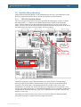
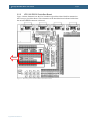
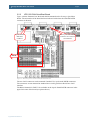
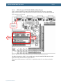
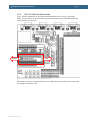
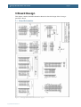
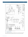
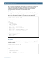
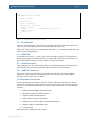
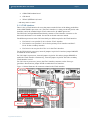
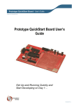
Prototype QuickStart Board - User’s Guide
Copyright 2005 © Embedded Artists AB
Prototype QuickStart Board
User’s Guide
Get Up-and-Running Quickly and
Start Developing on Day 1…
EA2-USG-0509 v1.1 Rev B
Prototype QuickStart Board - User’s Guide
Page 2
Embedded Artists AB
Friisgatan 33
SE-214 21 Malmö
Sweden
[email protected]
http://www.EmbeddedArtists.com
Copyright 2005 © Embedded Artists AB. All rights reserved.
No part of this publication may be reproduced, transmitted, transcribed, stored in a retrieval
system, or translated into any language or computer language, in any form or by any means,
electronic, mechanical, magnetic, optical, chemical, manual or otherwise, without the prior
written permission of Embedded Artists AB.
Disclaimer
Embedded Artists AB makes no representation or warranties with respect to the contents
hereof and specifically disclaim any implied warranties or merchantability or fitness for any
particular purpose. Information in this publication is subject to change without notice and
does not represent a commitment on the part of Embedded Artists AB.
Feedback
We appreciate any feedback you may have for improvements on this document. Please send
your comments to [email protected].
Trademarks
InfraBed and ESIC are trademarks of Embedded Artists AB. All other brand and product
names mentioned herein are trademarks, services marks, registered trademarks, or registered
service marks of their respective owners and should be treated as such.
Copyright 2005 © Embedded Artists AB
Prototype QuickStart Board - User’s Guide
Page 3
Table of Contents
1 Introduction
4
1.1
Contents
4
1.2
Features
4
1.3
Low Cost QuickStart Boards
5
1.3.1
1.4
Design and Production Services
5
Other QuickStart Boards and Kits
5
2 Getting Started
6
2.1
Power Supply
6
2.2
QuickStart Board Mounting
7
2.2.1
LPC2106 QuickStart Board
7
2.2.2
LPC2106 RS232 QuickStart Board
8
2.2.3
LPC2129 CAN QuickStart Board
9
2.2.4
LPC213x and LPC2148 USB QuickStart Board
10
2.2.5
LPC2103 USB QuickStart Board
11
3 Board Design
3.1
Board Schematics
12
3.2
7-segment Display
13
3.3
MMC/SD Memory Card Interface
14
3.4
Buzzer
15
3.5
LEDs
15
3.6
Push Buttons
16
3.7
RS232 ISP
16
3.8
CAN Connectors
16
3.9
UART #1 Connector
16
3.10
Expansion Connector
16
3.11
JTAG Interface
17
3.12
Prototype Area
18
4 Getting Started
19
4.1
Test Program
19
4.2
Program Development
19
5 CD-ROM and Product Registration
20
5.1
CD-ROM
20
5.2
Product Registration
20
6 Further Information
Copyright 2005 © Embedded Artists AB
12
21
Prototype QuickStart Board - User’s Guide
Page 4
1 Introduction
Thank you for buying Embedded Artists’ Prototype QuickStart Board, possibly together
with another QuickStart Board based on Philips ARM7TDMI LPC2xxx microcontroller
family.
This document is a User’s Guide that describes the Prototype QuickStart Board design. For
information regarding program development with our QuickStart Development Environment
see the document: QuickStart Program Development User's Guide.
1.1 Contents
The box received when ordering the Prototype QuickStart Board contains the following:
•
The Prototype QuickStart Board.
•
CD-ROM which includes additional material and programs, including complete and
evaluation versions of different development environments.
•
Possibly also another QuickStart Board with a LPC2xxx microcontroller.
1.2 Features
Embedded Artists’ Prototype QuickStart Board lets you get up-and-running quickly with our
LPC2xxx QuickStart Boards in general and in particular with Philips ARM7TDMI LPC2xxx
microcontroller. The features are summarized below:
•
Prototype board for many different QuickStart Boards. Different headers are used
for different boards.
−
LPC2106 QuickStart Board
−
LPC2106 RS232 QuickStart Board
−
LPC2129 CAN QuickStart Board
−
LPC213x QuickStart Board
−
LPC2148 USB QuickStart Board
−
LPC2103 USB QuickStart Board
•
Large prototype area (100 mil hole spacing)
•
Smaller prototype area with 50 mil hole spacing
•
SMD area for 50 mil SO circuits
•
SMD area for 0.65 mm SSOP circuits
•
MMC/SD connector, connected to SPI bus
•
7-segment display connected to SPI bus
•
16 LEDs
•
4 switches
•
Reset button
•
JTAG connector
•
9-pole DSUB connector for UART #1
Copyright 2005 © Embedded Artists AB
Prototype QuickStart Board - User’s Guide
Page 5
•
Power supply 5VDC (center pin negative) or 9VDC (any polarity) or 6VAC or from
USB connector (5V DC)
•
Two 9-pole DSUB connectors for CAN board (not mounted)
•
RS232 circuit for LPC2106 board (only partly mounted)
•
2x32 pole expansion connector compatible with the Education Board series.
•
196 x 125 mm in size
1.3 Low Cost QuickStart Boards
Embedded Artists’ LPC2xxx QuickStart Boards are very low cost and can be used for
prototyping / development as well as for OEM applications. Modifications for OEM
applications can be done easily, even for modest production volumes. Contact Embedded
Artists for further information about design and production services.
1.3.1
Design and Production Services
Embedded Artists provide design services for custom designs, either completely new or
modification to existing boards. Specific peripherals and I/O can be added easily to different
designs, for example, communication interfaces, specific analog or digital I/O, and power
supplies. Embedded Artists has a broad, and long, experience in designing industrial
electronics, in general, and with Philips LPC2xxx microcontroller family, in specific. Our
competence also includes wireless and wired communication for embedded systems. For
example IEEE802.11b/g (WLAN), Bluetooth™, ZigBee™, ISM RF, Ethernet, CAN,
RS485, and Fieldbuses.
1.4 Other QuickStart Boards and Kits
Visit Embedded Artists’ home page, www.EmbeddedArtists.com, for information about
other QuickStart boards / kits or contact your local distributor.
Copyright 2005 © Embedded Artists AB
Prototype QuickStart Board - User’s Guide
Page 6
2 Getting Started
2.1 Power Supply
There are four options for powering the Prototype QuickStart Board:
•
A DC power supply, 5 volt, capable of providing at least 150 mA (more if external
circuits need power from the 3.3 volt supply on the LPC2xxx QuickStart Boards).
The 2.1mm connector have negative center pin. The board contains reverse polarity
protection.
•
A DC power supply, 9 volt, with any polarity on the 2.1mm connector. Also in this
case, the power supply should be capable of providing at least 150 mA (more if
external circuits need power from the 3.3 volt supply on the LPC2xxx QuickStart
Boards).
•
An AC power supply, 6 volt. Also in this case, the power supply should be capable
of providing at least 150 mA (more if external circuits need power from the 3.3 volt
supply on the LPC2xxx QuickStart Boards).
•
Powering via a USB cable of type: B-to-A, both male connectors. In this case, the
power comes from a PC or a USB hub.
See Figure 1 below for details about power supply connectors (upper right corner of the
board).
USB Connector,
only for
powering
+5V DC, center
pin negative,
2.1mm connector
Figure 1 – Power Supply Connectors
Copyright 2005 © Embedded Artists AB
+9V DC, any
polarity, or 6V AC,
2.1mm connector
Prototype QuickStart Board - User’s Guide
Page 7
2.2 QuickStart Board Mounting
Many different QuickStart Boards can be mounted on the Prototype QuickStart Board. The
following subsection describes how to mount each different QuickStart Board.
2.2.1
LPC2106 QuickStart Board
The LPC2106 QuickStart Board is the only QuickStart board that does not have on-board
ISP functionality, i.e., a RS232 serial channel and automatic control of the bootloader.
Figure 2 below illustrates how the board shall be mounted on the Prototype QuickStart
Board. The orientation of the board has been indicated with where the crystal is on the board
and where the power supply is located (where the 20-pin chip is).
Jumpers to
enable ISP
9-pos female
DSUB
SP3232E RS232
interface
Crystal
Power
supply with
tantals caps.
Figure 2 – Mounting of the LPC2106 QuickStart Board
Almost all components for the ISP functionality have been mounted. The only things
missing are the SP3232E RS232 interface chip (in SO16) and the 9-pole female DSUB
connector. The 3232E chip is a standard ship that many produce. Sipex or any other
manufacturer can be used. The reason why these two components are not mounted is cost.
All other QuickStart Boards have on-board ISP functionality and it’s wasteful to mount these
components on all boards when only a few uses it. This allows us to produce and offer the
board to a lower cost.
The jumpers (as indicated in the picture above) are used to enable the ISP functionality.
Insert all four jumpers to enable automatic program download.
Copyright 2005 © Embedded Artists AB
Prototype QuickStart Board - User’s Guide
2.2.2
Page 8
LPC2106 RS232 QuickStart Board
Figure 3 below illustrates how the LPC2106 RS232 QuickStart Board shall be mounted on
the Prototype QuickStart Board. The orientation of the board has been indicated with where
the on-board DSUB connector is directed.
DSUB
Figure 3 – Mounting of the LPC2106 RS232 QuickStart Board
Copyright 2005 © Embedded Artists AB
Prototype QuickStart Board - User’s Guide
2.2.3
Page 9
LPC2129 CAN QuickStart Board
Figure 4 below illustrates how the board shall be mounted on the Prototype QuickStart
Board. The orientation of the board has been indicated with where the on-board DSUB
connector is directed.
9-pole female
DSUB for
UART #1
Two 9-pole male DSUB
connectors for CAN bus
Not mounted
DSUB
Figure 4 – Mounting of the LPC2129 CAN QuickStart Board
The two CAN connectors can be mounted if needed. Use 9-pole male DSUB connectors.
The connectors are not mounted as standard since not all QuickStart Board have CAN
interface.
The RS232 channel for UART #1is available on the 9-pole female DSUB connector in the
upper left corner of the board (see picture above).
Copyright 2005 © Embedded Artists AB
Prototype QuickStart Board - User’s Guide
2.2.4
Page 10
LPC213x and LPC2148 USB QuickStart Board
Figure 5 below illustrates how the board shall be mounted on the Prototype QuickStart
Board. The orientation of the board has been indicated with where the on-board DSUB and
USB connectors are directed.
9-pole female
DSUB for
UART #1
DSUB
USB
Figure 5 – Mounting of the LPC213x QuickStart Board and LPC2148 USB QuickStart Board
The RS232 channel for UART #1is available on the 9-pole female DSUB connector in the
upper left corner of the board (see picture above).
Note that the USB connector on the LPC213x QuickStart Board is only for powering the
board.
Copyright 2005 © Embedded Artists AB
Prototype QuickStart Board - User’s Guide
2.2.5
Page 11
LPC2103 USB QuickStart Board
Figure 6 below illustrates how the board shall be mounted on the Prototype QuickStart
Board. The orientation of the board has been indicated with where the on-board DSUB and
USB connectors are directed.
DSUB
USB
Figure 6 – Mounting of the LPC2103 USB QuickStart Board
This board has not been released when this User’s Manual is being written, but is expected to
be available in February 2006.
Copyright 2005 © Embedded Artists AB
Prototype QuickStart Board - User’s Guide
3 Board Design
This chapter contains detailed information about the electrical design of the Prototype
QuickStart Board.
3.1 Board Schematics
Figure 7 – Prototype QuickStart Board Schematic, page 1
Copyright 2005 © Embedded Artists AB
Page 12
Prototype QuickStart Board - User’s Guide
Page 13
Figure 8 – Prototype QuickStart Board Schematic, page 2
3.2 7-segment Display
The 7-segment display is connected to the SPI bus. P0.23 is used as chip select for the shift
register that is used to shift in the display content. Figure 9 below lists a small example
Copyright 2005 © Embedded Artists AB
Prototype QuickStart Board - User’s Guide
Page 14
program how to control the display. Note that the decimal dot on the 7-segment display does
not work (there is no LED).
#
# Example program to control the 7-segment display
#
#include <lpc2xxx.h>
#define SPI_CS 0x00800000
//P0.23
const tU8 to7Segment[10] = {0x3f,0x06,0x5b,0x4f,0x66,0x6d,0x7d,0x07,0x7f,0x6f};
void
initDisplay(void)
{
//enable SPI in pins
PINSEL0 &= 0xffff00ff;
PINSEL0 |= 0x00005500;
//or 0xffff30ff if LPC2148
//or 0x00001500 if LPC2148
//initialize SPI to highest speed
SPI_SPCCR = 0x00000008;
SPI_SPCR = 0x00000038;
//Set P0.23 as output and set the pin high
IODIR0
|= SPI_CS;
IOSET0
= SPI_CS;
//blank the display, a high bit = LED segment off
sendSPI(0xff);
}
void
sendSPI(unsigned char inData)
{
IOCLR0 = SPI_CS; //Activate SPI slave
SPI_SPDR = inData;
while((SPI_SPSR & 0x80) == 0)
;
IOSET0 = SPI_CS; //Deactivate SPI slave
}
void
setDisplay(unsigned char digit)
{
sendSPI(~to7Segment[digit]);
}
Figure 9 – Example program to control the 7-segment display
Note that there is normally no need to have SPI_MISO (P0.5) jumper in J30 inserted.
3.3 MMC/SD Memory Card Interface
The MMC/SD memory card interface is also connected to the SPI bus. In this case, P0.22 is
used as chip select of the memory card.
There is an application note form Philips (AN10406_1: Accessing SD/MMC card using SPI
on LPC2000) that describes how to create a low level interface (read/write sectors) to the
memory cards.
The memory card connector also contains switches to detect if a card is inserted or not.
P0.29 is connected to the card detect switch. A low level indicated that a memory card is
present/inserted in the connector. There is also a write protect switch that is used on SD
memory cards (note that MMC cards do not include this feature). A low level on pin P0.30
indicates that write operations are allowed on the memory card.
Copyright 2005 © Embedded Artists AB
Prototype QuickStart Board - User’s Guide
Page 15
Do not forget that you must insert the jumpers in pin list J22 in order to use the interface. J41
can be found just to the right of the memory card connector. If you do not use the extra
switches (for insertion detection and write protect detection) just do not insert these
corresponding jumpers. These are the two top-most jumpers on J22.
3.4 Buzzer
The buzzer is connected to pin P0.7. Either the buzzer is controlled by a simple digital
signal; high is off, and a low signal turns the buzzer on. In this case, the buzzer oscillates in
its self-frequency. As an alternative, a PWM signal can be used to control the frequency of
the oscillations. The signal PWM2 is available as an alternative signal on pin P0.7. Figure 10
below lists a small example program how to control the buzzer with a PWM signal.
#
# Example program to control the buzzer
#
#include <lpc2xxx.h>
void
initPWM2(void)
{
//enable PWM2 on P0.7
PINSEL0 &= 0xffff3fff;
PINSEL0 |= 0x00008000;
//initialize PWM2
PWM_PR = 0x00;
PWM_MCR = 0x02;
PWM_MR0 = 0x1000;
PWM_MR2 = 0x1000;
PWM_LER = 0x05;
PWM_PCR = 0x0400;
PWM_TCR = 0x09;
//Prescale Register
//Match Control Register
//Latch Enable Register
//Prescale Counter Register PWMENA2
//Counter Enable och PWM Enable
}
void
setBuzzer(unsigned int frequency)
{
PWM_MR0 = frequency;
PWM_MR2 = frequency / 2;
PWM_LER = 0x05;
}
Figure 10 – Example program to control the buzzer
3.5 LEDs
16 LEDs are connected to pins P0.8 – P0.15. A low pin level drives current through the LED
(i.e., LED is on). Figure 11 below lists a small example program how to control the LEDs in
a running-one pattern.
#
# Example program to control the LEDs
#
#include <lpc2xxx.h>
void
initLEDs(void)
{
//set P0.8-p0.23 to outputs
PINSEL0 &= 0x0000ffff;
PINSEL1 &= 0xffff0000;
IODIR
|= 0x00ffff00;
IOSET
= 0x00ffff00; //turn all LEDs off
}
Copyright 2005 © Embedded Artists AB
Prototype QuickStart Board - User’s Guide
Page 16
void
runningLEDs(unsigned int rounds)
{
unsigned int pattern;
while(rounds-- > 0)
{
pattern = 0x00000100;
while (pattern < 0x01000000)
{
IOCLR0 = pattern;
delay();
//user-defined delay function
IOSET0 = pattern;
pattern <<= 1;
}
}
}
Figure 11 – Example program to control the LEDs
3.6 Push Buttons
There are five push buttons on the Prototype QuickStart Board. On if for reset and the four
other are connected to pins: P0.14, P0.15, P0.16 and P0.30 respectively.
These pins can be useful to have a push button connected to. As alternative signals these pins
can be used an interrupt inputs.
3.7 RS232 ISP
As explained in Section 2.2.1 , this circuit is only included since the LPC2106 QuickStart
Boards do not include the ISP functionality. You must add a SP3232E circuit as well as a 9pole female DSUB connector in order to make use if this functionality.
3.8 CAN Connectors
These connectors are only used with the LPC2129 CAN QuickStart Board. The two 9-pole
male DSUB connectors must be manually soldered in order to use this interface.
3.9 UART #1 Connector
The LPC2129, LPC213x, and LPC2148 QuickStart Boards have also on-board RS232
support for UART channel #1. When these boards are used, this 9-pole female DSUB
connector can be used to access UART #1.
3.10 Expansion Connector
The 2x32 pin expansion connector allows the Expansion Boards in the Education Board
series to be used and connected to the Prototype QuickStart Board. The list below presents
the first set of available expansion boards. As seen, many of the boards are communication
oriented.
•
Ethernet board (10Mbps) with SPI interface
•
Bluetooth™ board with UART interface
•
ZigBee™ board with SPI interface
•
MP3 decoder board with SPI interface
•
Graphical LCD (240x120 pixels) with parallel interface
•
Modem (UART#1) and RS485 board
•
Prototype board
More boards are in preparation, for example:
Copyright 2005 © Embedded Artists AB
Prototype QuickStart Board - User’s Guide
•
GSM/GPRS modem board
•
GPS board
•
WLAN (IEEE802.11) board
Page 17
…and many more to come!
3.11 JTAG Interface
There is also a JTAG interface for users that want to make full use of the debug possibilities
in the ARM7TDMI-S processor core. The JTAG interface is a 2x10 pin 100 mil pin list with
shoulders, and is the standard 20-pin JTAG connector for all ARM7-processors.
The LPC2129 CAN QuickStart Board already contains a JTAG interface connector so for
this board, this feature is not needed. Just use the on-board connector instead.
The different processors in the LPC2xxx family use different pins for the JTAG interface:
•
LPC2101/2/3 uses pins P0.27-P0.31 for the JTAG interface
•
LPC2104/5/6 uses pins P0.17-P0.21 for the primary JTAG interface and P0.27P0.31 for the secondary interface.
•
LPC212x/3x/4x uses pins P1.27-P1.31 for the JTAG interface
For the LPC2101/2/3 processors; insert all jumpers in pin list J32 and use jumper DBGSEL
to enable the JTAG interface.
For LPC2104/5/6 processors, insert all jumpers in pin list J12 and use jumper DBGSEL to
enable the JTAG interface. Alternatively, insert all jumpers in pin list J18 if the secondary
JTAG interface is used.
For LPC213x/4x processors, just use the JTAG interface connector on the Prototype
QuickStart Board and use jumper RTCK to enable the JTAG interface.
Figure 12 below illustrates all connectors related to the JTAG interface.
The 20-pin
JTAG-interface
Enable JTAG
(RTCK)
Enable JTAG
(DBGSEL)
For LPC2101/2/3
Pin list J18
For LPC2104/5/6
Pin list J12
Figure 12 – JTAG connectors
Copyright 2005 © Embedded Artists AB
Prototype QuickStart Board - User’s Guide
Page 18
3.12 Prototype Area
Finally, and maybe most importantly, there are six different parts that make up the prototype
area:
•
The largest and most obvious part is the 100 mil connection array.
•
All pins signals from the QuickStart Boards are available at the left and upper edges
of the area.
•
The top right edge of the area contains power connections for +5 Volt, +3.3 Volt,
and GND.
•
A small 50 mil connection area at the right bottom area.
•
A 50 mil (1.27 mm) area at the right edge for connecting SO-sized circuits.
•
A 0.65mm area at the bottom for connecting SSOP-sized circuits.
Copyright 2005 © Embedded Artists AB
Prototype QuickStart Board - User’s Guide
Page 19
4 Getting Started
4.1 Test Program
The Prototype QuickStart Board does not contain a processor and can therefore not have any
preloaded test program. However, there exist two different test programs that can be
downloaded in the LPC2xxx QuickStart Board that is connected to the Prototype QuickStart
Board:
•
Test program for QuickStart Boards with a 12.0000MHz crystal.
Use terminal baud rate 38400 bps, 8 data bits, no parity bit, one stop bit.
•
Test program for QuickStart Boards with a 14.745600MHz crystal.
Use terminal baud rate 115200 bps, 8 data bits, no parity bit, one stop bit.
The test program outputs a running-one on the LEDs, writes digits to the 7-segment display
and plays a simple song on the buzzer.
4.2 Program Development
Consult the QuickStart Program Development User’s Manual for more information about
the QuickStart Build Environment from Embedded Artists, and program development for the
ARM7 in general.
Copyright 2005 © Embedded Artists AB
Prototype QuickStart Board - User’s Guide
Page 20
5 CD-ROM and Product Registration
The accompanying CD-ROM contains a lot of information and programs that will
QuickStart your program development! Note that there may be newer versions of different
documents and programs available than the ones on the CD-ROM. See Section 5.2 for
information about the product registration process, which allows you to always have access
to the latest versions.
5.1 CD-ROM
The following is included on the CD-ROM:
•
The test programs as HEX-files.
•
The two different ISP download programs.
•
Datasheets of all circuits on the Prototype QuickStart Board.
•
QuickStart Build Environment from Embedded Artists, which contains a complete
setup of a build environment for GCC.
•
A complete development environment: Rowley Associates CrossWorks for ARM,
30-day evaluation version.
•
A complete development environment: IAR Embedded Workbench for ARM,
Kickstart Edition with 32 Kbyte program size limit.
•
Another complete development environment: GCC, GNUARM distribution,
including compiler, linker, make, and debugger.
•
The program Programmers Notepad, which is a very good program development
editor and project manager.
•
The Eclipse development environment including the CDT (C/C++ Development
Tools) project.
5.2 Product Registration
By registering as a customer of Embedded Artists you will always have access to the latest
versions of all information and programs on the CD-ROM.
Registering is easy and done quickly.
1) Go to http://www.EmbeddedArtists.com, select Support and then Register.
2) Type in the products serial number (can be found on the Prototype QuickStart Board
or on the package carrying the board) along with your personal information.
Copyright 2005 © Embedded Artists AB
Prototype QuickStart Board - User’s Guide
Page 21
6 Further Information
LPC2xxx microcontrollers are complex circuits and there exist a number of other documents
with a lot more information. The following documents are recommended as a complement to
this document.
[1] Philips LPC2xxx Datasheet
[2] Philips LPC2xxx User’s Manual
[3] Philips LPC2xxx Errata Sheet
[4] ARM7TDMI Technical Reference Manual. Document identity: DDI0029G
http://www.arm.com/pdfs/DDI0029G_7TDMI_R3_trm.pdf
[5] ARM Architecture Reference Manual. Document identity: DDI0100E
Book, Second Edition, edited by David Seal, Addison-Wesley: ISBN 0-201-73719-1
Also available in PDF form on the ARM Technical Publications CD
[6] ARM System Developer’s Guide – Designing and Optimizing System Software, by
A.N. Sloss, D Symes, C. Wright. Elsevier: ISBN 1-55860-874-5
[7] Embedded System Design on a Shoestring, by Lewin Edwards.
Newnes: ISBN 0750676094.
[8] GNU Manuals
http://www.gnu.org/manual/
[9] GNU ARM tool chain for Cygwin
http://www.gnuarm.com
[10] An Introduction to the GNU Compiler and Linker, by Bill Gatliff
http://www.billgatliff.com
[11] LPC2000 Yahoo Group. A discussion forum dedicated entirely to the Philips
LPC2xxx series of microcontrollers.
http://groups.yahoo.com/group/lpc2000/
[12] The Insider’s Guide to the Philips ARM7-Based Microcontrollers, by Trevor Martin.
http://www.hitex.co.uk/arm/lpc2000book/index.html
Note that there can be newer versions of the documents than the ones linked to here. Always
check for the latest information / version.
Copyright 2005 © Embedded Artists AB