1
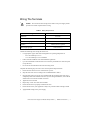
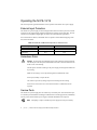
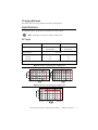
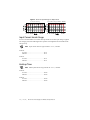
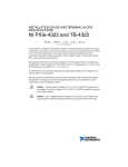
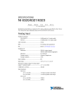
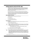
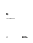
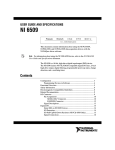
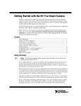
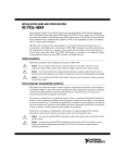
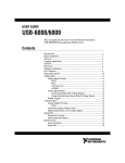
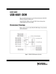
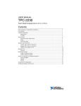
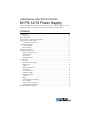
USER MANUAL AND SPECIFICATIONS NI PS-12/13 Power Supply This document describes the features and specifications of the NI PS-12 and NI PS-13 power supplies and contains information about installing and using these power supplies. Contents Introduction .............................................................................................................................. 2 Key Features ..................................................................................................................... 2 Safety Information.................................................................................................................... 3 Electromagnetic Compatibility Information............................................................................. 5 What You Need to Get Started ................................................................................................. 6 Unpacking and Connecting .............................................................................................. 6 Connector Descriptions ............................................................................................................ 6 Output Terminals.............................................................................................................. 6 Input Terminals................................................................................................................. 6 Wiring The Terminals .............................................................................................................. 7 Operating the NI PS-12/13 ....................................................................................................... 8 External Input Protection.................................................................................................. 8 Hazardous Risks ............................................................................................................... 8 Service Parts ..................................................................................................................... 8 Charging Batteries ............................................................................................................ 9 Specifications............................................................................................................................ 9 AC Input ........................................................................................................................... 9 Input Current Inrush Surge ............................................................................................... 10 Hold-up Time ................................................................................................................... 10 Output ............................................................................................................................... 11 Physical Characteristics.................................................................................................... 11 Environment ..................................................................................................................... 13 Protection Features ........................................................................................................... 14 Withstand Voltage ............................................................................................................ 15 Isolation Resistance .......................................................................................................... 15 Vibration........................................................................................................................... 15 Safety ................................................................................................................................ 15 Electromagnetic Compatibility......................................................................................... 16 CE Compliance................................................................................................................. 16 Online Product Certification............................................................................................. 16 Environmental Management............................................................................................. 16 Worldwide Support and Services ............................................................................................. 17 Introduction Key Features The key features of the NI PS-12/13 power supply include the following: • Universal input voltage range • 24 V (NI PS-12) or 48 V (NI PS-13) output, manually adjustable output voltage (±10%) • Peak current for motor applications • Protections: short circuit, overload, over voltage Hazardous Voltage The NI PS-12/13 must be installed in a suitable enclosure prior to use. Hazardous voltages are present. This power supply is intended for general use, such as in industrial control and instrumentation equipment. Do not use this device in aircraft, trains, and nuclear equipment, where malfunctioning of the power supply may cause severe personal injury or threaten human life. For more information, refer to the Specifications section. Figure 1 shows the power supply terminals. Figure 1. NI PS-12/13 Power Supply Terminals Serial No. Made in China Made in China +V+V ADJ ADJ OUTPUT: 48V + + 6.7A +V +V 1 1 2 3 2 INPUT: 100-240VAC 5A 50/60Hz -V-V 2 NN L L 3 4 +24 V (NI PS-12) or +48 V (NI PS-13) Output +24 V (NI PS-12) or +48 V (NI PS-13) Ground AC Input Ground (Protective Earth) | ni.com | NI PS-12/13 Power Supply User Manual and Specifications 5 4 5 AC Input Neutral AC Input Line Safety Information The following section contains important safety information that you must follow when installing and using the hardware. Do not operate the hardware in a manner not specified in this document and in the user documentation. Misuse of the hardware can result in a hazard. You can compromise the safety protection if the hardware is damaged in any way. If the hardware is damaged, return it to National Instruments for repair. When this symbol is marked on a product, refer to the hardware documentation for information about precautions to take. When this symbol is marked on a product, it denotes a warning advising you to take precautions to avoid electrical shock. When this symbol is marked on a product, it denotes a component that may be hot. Touching this component may result in bodily injury. Clean the hardware with a soft, nonmetallic brush. Make sure that the hardware is completely dry and free from contaminants before returning it to service. Do not substitute parts or modify the hardware except as described in this document. Use the hardware only with the chassis, modules, accessories, and cables specified in the installation instructions or specifications. You must have all covers and filler panels installed during operation of the hardware. Do not operate the hardware in an explosive atmosphere or where there may be flammable gases or fumes unless the hardware is UL (U.S.) or Ex (EU) Certified and marked for hazardous locations. The hardware must be in a suitably rated IP 54 minimum enclosure for hazardous locations. Refer to the hardware documentation for more information. You must insulate signal connections for the maximum voltage for which the hardware is rated. Do not exceed the maximum ratings for the hardware. Do not install wiring while the hardware is live with electrical signals. Do not remove or add connector blocks when power is connected to the system. Avoid contact between your body and the connector pins when hot-swapping hardware. Remove power from signal lines before connecting them to or disconnecting them from the hardware. NI PS-12/13 Power Supply User Manual and Specifications | © National Instruments | 3 Operate the hardware only at or below Pollution Degree 2. Pollution is foreign matter in a solid, liquid, or gaseous state that can reduce dielectric strength or surface resistivity. The following is a description of pollution degrees: • Pollution Degree 1 means no pollution or only dry, nonconductive pollution occurs. The pollution has no influence. Typical level for sealed components or coated PCBs. • Pollution Degree 2 means that only nonconductive pollution occurs in most cases. Occasionally, however, a temporary conductivity caused by condensation must be expected. Typical level for most products. • Pollution Degree 3 means that conductive pollution occurs, or dry, nonconductive pollution occurs that becomes conductive due to condensation. Operate the hardware at or below the measurement category1 marked on the hardware label. Measurement circuits are subjected to working voltages2 and transient stresses (overvoltage) from the circuit to which they are connected during measurement or test. Measurement categories establish standard impulse withstand voltage levels that commonly occur in electrical distribution systems. The following is a description of measurement categories: • Measurement Categories CAT I and CAT O (Other) are equivalent and are for measurements performed on circuits not directly connected to the electrical distribution system referred to as MAINS3 voltage. This category is for measurements of voltages from specially protected secondary circuits. Such voltage measurements include signal levels, special hardware, limited-energy parts of hardware, circuits powered by regulated low-voltage sources, and electronics. • Measurement Category II is for measurements performed on circuits directly connected to MAINS. This category refers to local-level electrical distribution, such as that provided by a standard wall outlet (for example, 115 AC voltage for U.S. or 230 AC voltage for Europe). Examples of Measurement Category II are measurements performed on household appliances, portable tools, and similar hardware. • Measurement Category III is for measurements performed in the building installation at the distribution level. This category refers to measurements on hard-wired hardware such as hardware in fixed installations, distribution boards, and circuit breakers. Other examples are wiring, including cables, bus bars, junction boxes, switches, socket outlets in the fixed installation, and stationary motors with permanent connections to fixed installations. • Measurement Category IV is for measurements performed at the primary electrical supply installation typically outside buildings. Examples include electricity meters and measurements on primary overcurrent protection devices and on ripple control units. To obtain the safety certification(s) for this product, visit ni.com/certification, search by model number or product line, and click the appropriate link in the Certification column. 1 2 3 4 Measurement categories, also referred to as overvoltage or installation categories, are defined in electrical safety standards IEC 61010-1 and IEC 60664-1. Working voltage is the highest rms value of an AC or DC voltage that can occur across any particular insulation. MAINS is defined as a hazardous live electrical supply system that powers hardware. Suitably rated measuring circuits may be connected to the MAINS for measuring purposes. | ni.com | NI PS-12/13 Power Supply User Manual and Specifications Electromagnetic Compatibility Information This hardware has been tested and found to comply with the applicable regulatory requirements and limits for electromagnetic compatibility (EMC) as indicated in the hardware’s Declaration of Conformity (DoC)1. These requirements and limits are designed to provide reasonable protection against harmful interference when the hardware is operated in the intended electromagnetic environment. In special cases, for example when either highly sensitive or noisy hardware is being used in close proximity, additional mitigation measures may have to be employed to minimize the potential for electromagnetic interference. When this symbol is marked on a product, refer to the hardware documentation for information about precautions to take. This hardware complies with the applicable regulatory EMC requirements, but some interference may occur in particular installations. To minimize interference with radio and television reception and to prevent unacceptable performance degradation, install and use this hardware in strict accordance with the instructions in the hardware documentation and the DoC1. If this hardware does cause interference with licensed radio communications services or other nearby electronics, which can be determined by turning the hardware off and on, NI recommends that you try the following measures: • Reorient the antenna of the receiver (the device suffering interference). • Relocate the transmitter (the device generating interference) with respect to the receiver. • Plug the transmitter into a different outlet so that the transmitter and the receiver are on different branch circuits. Some hardware may require the use of a metal, shielded enclosure (windowless version) to meet the EMC requirements for special EMC environments such as marine and heavy industrial areas. Refer to the hardware documentation and the DoC1 for product installation requirements. When the hardware is connected to a test object or to test leads, the system may become more sensitive to disturbances or may cause interference in the local electromagnetic environment. Operation of this hardware in a residential area is likely to cause harmful interference. Users are required to correct the interference at their own expense or cease operation of the hardware. Changes or modifications not expressly approved by National Instruments could void the user’s right to operate the hardware under the local regulatory rules. 1 The Declaration of Conformity (DoC) contains important EMC compliance information and instructions for the user or installer. To obtain the DoC for this product, visit ni.com/certification, search by model number or product line, and click the appropriate link in the Certification column. NI PS-12/13 Power Supply User Manual and Specifications | © National Instruments | 5 What You Need to Get Started The NI PS-12/13 power supply kit contains the following items: NI PS-12 or NI PS-13 power supply Unpacking and Connecting The following steps provide a high-level overview for connecting the power supply to AC and to other devices. Refer to the Connector Descriptions section for detailed information about each connector. 1. Remove the NI PS-12/13 from the package. 2. Carefully inspect the shipping container and the power supply for damage. Check for visible damage to the metal work. If damage appears to have been caused during shipment, file a claim with the carrier. Retain the packing material for possible inspection and/or reshipment. 3. Mount the NI PS-12/13, if necessary. Refer to Figure 6 for mounting hole locations. 4. Connect the AC input cable to the line, neutral, and protective earth connectors. 5. Connect external device(s) to the power supply +V and -V connectors. Connector Descriptions Output Terminals The NI PS-12 and NI PS-13 have a total of four output terminals, providing two positive (+) output terminals and two negative (-) output terminals. Both positive terminals are wired together internally, and both negative terminals are wired together internally. Input Terminals The NI PS-12/13 power supply derives power through the input terminals on the front panel. There are three terminals corresponding to the Neutral input, the Line (or hot) input, and the Protective Earth (PE) input. The NI PS-12/13 rectifies both single-phase and two-phase AC input. The Neutral input terminal provides a MAINS return path for the input circuitry. The Line input is the primary power input for the supply. The PE input corresponds to an earth ground. The power supply case itself is grounded to the PE input. National Instruments recommends that you wire all three input terminals for proper operation of the NI PS-12/13. Caution 6 | ni.com | NI PS-12/13 Power Supply User Manual and Specifications Wiring The Terminals Caution This section describes wiring for the NI PS-12/13 power supply. Table 1 provides a list of basic requirements for wiring. Table 1. Wiring Requirements Type Screw Terminals Solid wire 0.5-6 mm Stranded wire 0.5-4 mm American wire gauge Ferrules 20-10 AWG Allowed, but not required Wire stripping length 7 mm (0.275 in.) Consider the following when wiring the NI PS-12/13. • Use appropriate copper cables that are designed for an operating temperature of: – 60 °C for ambient up to 45 °C. – 75 °C for ambient up to 60 °C minimum. • Follow national installation codes and installation regulations. • Up to two stranded wires with the same cross section are permitted in one connection point (except PE wire). • Do not use the unit without the PE connection being wired. Complete the following steps to connect wires to the input and output terminals. 1. Ensure that none of the wires are connected to live power. 2. Strip the ends of the wires according to the recommendations in Table 1. 3. Insert the end of the wire into the screw terminal until the exposed portion of the wire is completely inside of the terminal connection. If you are using stranded wire, ensure that all strands of the wire enter the terminal connection. 4. Tighten the screw terminal. 5. Repeat steps 3-4 for each of the other terminals. 6. Ensure that all wires are properly seated and not loose. 7. Ensure that the rest of your equipment is ready to be powered without creating a hazard. 8. Apply MAINS voltage to the power supply. NI PS-12/13 Power Supply User Manual and Specifications | © National Instruments | 7 Operating the NI PS-12/13 This section provides general information on the operation of the NI PS-12/13 power supply. External Input Protection The NI PS-12/13 power supply is tested and approved for branch circuits up to 20 A. External protection is only required if the supplying branch has an ampacity greater than 20 A. In some countries, local regulations might apply, so check local codes and local requirements. If an external fuse is utilized, a minimum value is required to avoid undesired tripping of the fuse, shown in Table 2. Table 2. Maximum and Minimum Ampacities for External Fuses Ampacity B-Characteristic C-Characteristic Minimum 10 A 6A Maximum 20 A 20 A Hazardous Risks Do not use the unit without the proper earth connection (Protective Earth). Use the PE pin on the front panel terminal block for earth connection instead of one of the screws on the housing. Caution Turn the power off before working on the power supply. Protect against inadvertent re-powering. Make sure the wiring is correct by following all local and national codes. Do not open, modify, or repair the unit. Use caution to prevent any foreign objects from entering into the housing. Do not use in wet locations or in areas where moisture or condensation can be expected. Service Parts The NI PS-12/13 power supply does not contain any serviceable parts. If an internal fuse trips, it is caused by an internal defect. If damage or malfunction occurs during operation, immediately turn the power off and send the power supply to National Instruments for inspection. Note 8 | ni.com | Attempting to repair or modify the power supply will void your warranty. NI PS-12/13 Power Supply User Manual and Specifications Charging Batteries The NI PS-12/13 power supply should not be used to charge batteries. Specifications This appendix contains specifications for the NI PS-12/13 power supply. Note Specifications are subject to change without notice. AC Input Input range NI PS-12 NI PS-13 85-265 VAC or 120-370 VDC 85-265 VAC or 120-370 VDC Input frequency 47-63 Hz Input current (A), typical* 115 VAC 230 VAC 1.8 0.9 3.6 1.8 * At maximum output power, nominal input voltage, Ta = 25° Figure 2. NI PS-12 Input Voltage Vs. Output Load Convection Cooling Forced Air Cooling (ventilation: 18CFM) Figure 3. NI PS-13 Input Voltage Vs. Output Load NI PS-12/13 Power Supply User Manual and Specifications | © National Instruments | 9 Figure 4. NI PS-13 Input Voltage Vs. Output Load Convection Cooling Forced Air Cooling (ventilation: 18CFM) Input Current Inrush Surge An active inrush limitation circuit limits the input inrush current after input voltage is applied. The charging current into EMI suppression capacitors is disregarded in the first milliseconds after power up. Note Input current values are typical with Ta = 25 °C, cold start. NI PS-12 115 VAC....................................................20 A 230 VAC....................................................40 A NI PS-13 115 VAC....................................................40 A 230 VAC....................................................80 A Hold-up Time Note Hold-up time values are typical with Ta = 25 °C, cold start. NI PS-12 115 VAC....................................................20 ms 230 VAC....................................................20 ms NI PS-13 115 VAC....................................................20 ms 230 VAC....................................................20 ms 10 | ni.com | NI PS-12/13 Power Supply User Manual and Specifications Output NI PS-12 NI PS-13 Output voltage, nominal (V) 24 48 Output current (A), maximum 6.3 6.7 Peak output current (A) 9.5 8.7 151.2 321.6 21.6-26.4 43.2-52.8 81% 84% 84% 88% Ripple and noise voltage (mV)*, ** 115 VAC 230 VAC 150 150 240 240 Line regulation (mV)** 96 96 Load regulation (mV)** 120 240 Leakage current (mA) 115 VAC 230 VAC 0.75 max, 0.25 typ 0.5 typ 0.75 max, 0.25 typ 0.5 typ Output power (W), maximum Output voltage range (V) Efficiency* 115 VAC 230 VAC * At maximum output power, nominal input voltage, Ta = 25° ** Measured at bandwidth of 20 MHz using a 12 inch twisted pair-wire terminated with a 0.1 µF and 47 µF parallel capacitor. Physical Characteristics Caution Clean the hardware with a soft, nonmetallic brush. Make sure that the hardware is completely dry and free from contaminants before returning it to service. NI PS-12 Dimensions ............................................... 169.93 × 99.06 × 50.04 mm (6.69 × 5.90 × 1.97 in.) Weight....................................................... 620 g (1.37 lb) NI PS-13 Dimensions ............................................... 198.88 × 99.06 × 51.82 mm (7.83 × 3.90 × 2.04 in.) Weight....................................................... 900 g (2.0 lb) NI PS-12/13 Power Supply User Manual and Specifications | © National Instruments | 11 Figure 5. NI PS-12 Dimensions 170 152 65 45 49.5 8 18 11.5MAX 9.5 63 99 4-M4 L=4mm 12.5 25 117 12 | ni.com | NI PS-12/13 Power Supply User Manual and Specifications 28 50 25 3-M4 L=4mm Figure 6. NI PS-13 Dimensions 4 x M4, 5mm deep FAN Direction of air flow 4 x M4, 5mm deep Bottom View Environment NI PS-12 ........................................................... -10 to 50 °C, convection cooling -10 to 70 °C, forced air cooling Convection Cooling Forced Air Cooling (ventilation: 18CFM) NI PS-12/13 Power Supply User Manual and Specifications | © National Instruments | 13 NI PS-13 ...........................................................-10 to 65 °C Storage temperature ..........................................-30 to 85 °C Operating humidity ...........................................20 to 90% RH, noncondensing Storage humidity ...............................................10 to 95% RH, noncondensing Cooling method NI PS-12 ...................................................Convection cooling or forced air cooling NI PS-13 ...................................................Forced air cooling by fan—on demand Indoor use only. Protection Features Overcurrent protection Caution Do not operate at overload or dead short for more than 60 seconds. NI PS-12 ...................................................6.6-9.7 A, constant current limit with automatic recovery NI PS-13 ...................................................7.0-10 A, constant current limit with automatic recovery Overvoltage protection NI PS-12 ...................................................27.6-32.4 V NI PS-13 ...................................................55.2-64.8 V Note In case of overvoltage event, the device shuts down output voltage. Manual reset of AC power is required to continue operation. Over temperature protection NI PS-12 ...................................................No Note In case of a protection event, audible noise may occur. NI PS-13 ...................................................Yes 14 | ni.com | NI PS-12/13 Power Supply User Manual and Specifications Note In case of over temperature event, the device shuts down output voltage. Manual reset of AC power is required to continue operation. Withstand Voltage NI PS-12 Input-output .............................................. 3.0 kVAC (20 mA) Input-FG ................................................... 2.0 kVAC (20 mA) Output-FG................................................. 500 VAC (20 mA) for 1 min NI PS-13 Input-output .............................................. 3.0 kVAC (10 mA) Input-FG ................................................... 2.0 kVAC (10 mA) Output-FG................................................. 500 VAC (10 mA) for 1 min Isolation Resistance NI PS-12 ........................................................... More than 100 MΩ at Ta = 25 °C and 70% relative humidity, Output-FG................................................. 500 VDC NI PS-13 ........................................................... More than 100 MΩ at Ta = 25 °C and 70% relative humidity, Output-FG................................................. 500 VDC Vibration NI PS-12 ........................................................... At non operation, 10-55 Hz, 10 min, 1 cycle, 19.6 m/s2 constant, X, Y, Z, 1 hour each NI PS-13 ........................................................... At non operation, 10-55 Hz, 10 min, 1 cycle, 19.6 m/s2 constant, X, Y, Z, 1 hour each Safety This product meets the requirements of the following standards of safety for electrical equipment for measurement, control, and laboratory use: • UL60950-1 • CSA60950-1 • EN60950-1 Note For UL and other safety certifications, refer to the product label or the Online Product Certification section. NI PS-12/13 Power Supply User Manual and Specifications | © National Instruments | 15 Electromagnetic Compatibility This product meets the requirements of the following EMC standards for electrical equipment for measurement, control, and laboratory use: • EN61000-4-2, EN61000-4-3, EN61000-4-4, EN61000-4-5, EN61000-4-6, EN61000-4-8, EN61000-4-11 • FCC-Class B • EN55011/EN55022-B • CISPR22 Class B For EMC declarations and certifications, refer to the Online Product Certification section. Note CE Compliance This product meets the essential requirements of applicable European Directives, as follows: • 2006/95/EC; Low-Voltage Directive (safety) • 2004/108/EC; Electromagnetic Compatibility Directive (EMC) Online Product Certification To obtain product certifications and the Declaration of Conformity (DoC) for this product, visit ni.com/certification, search by model number or product line, and click the appropriate link in the Certification column. Environmental Management NI is committed to designing and manufacturing products in an environmentally responsible manner. NI recognizes that eliminating certain hazardous substances from our products is beneficial to the environment and to NI customers. For additional environmental information, refer to the Minimize Our Environmental Impact web page at ni.com/environment. This page contains the environmental regulations and directives with which NI complies, as well as other environmental information not included in this document. Waste Electrical and Electronic Equipment (WEEE) At the end of the product life cycle, all products must be sent to a WEEE recycling center. For more information about WEEE recycling centers, National Instruments WEEE initiatives, and compliance with WEEE Directive 2002/96/EC on Waste and Electronic Equipment, visit ni.com/environment/ weee. EU Customers ⬉ᄤֵᙃѻક∵ᶧࠊㅵ⧚ࡲ⊩ ˄Ё RoHS˅ Ёᅶ᠋ National Instruments ヺড়Ё⬉ᄤֵᙃѻકЁ䰤ࠊՓ⫼ᶤѯ᳝ᆇ⠽䋼ᣛҸ (RoH ݇Ѣ National Instruments Ё RoHS ড়㾘ᗻֵᙃˈ䇋ⱏᔩ ni.com/environment/rohs_c (For information about China RoHS compliance, go to ni.com/environment/rohs_ 16 | ni.com | NI PS-12/13 Power Supply User Manual and Specifications Worldwide Support and Services The National Instruments website is your complete resource for technical support. At ni.com/ support you have access to everything from troubleshooting and application development self-help resources to email and phone assistance from NI Application Engineers. Visit ni.com/services for NI Factory Installation Services, repairs, extended warranty, and other services. Visit ni.com/register to register your National Instruments product. Product registration facilitates technical support and ensures that you receive important information updates from NI. A Declaration of Conformity (DoC) is our claim of compliance with the Council of the European Communities using the manufacturer’s declaration of conformity. This system affords the user protection for electromagnetic compatibility (EMC) and product safety. You can obtain the DoC for your product by visiting ni.com/certification. If your product supports calibration, you can obtain the calibration certificate for your product at ni.com/calibration. National Instruments corporate headquarters is located at 11500 North Mopac Expressway, Austin, Texas, 78759-3504. National Instruments also has offices located around the world. For telephone support in the United States, create your service request at ni.com/support or dial 512 795 8248. For telephone support outside the United States, visit the Worldwide Offices section of ni.com/niglobal to access the branch office websites, which provide up-to-date contact information, support phone numbers, email addresses, and current events. Refer to the NI Trademarks and Logo Guidelines at ni.com/trademarks for more information on National Instruments trademarks. Other product and company names mentioned herein are trademarks or trade names of their respective companies. For patents covering National Instruments products/technology, refer to the appropriate location: Help»Patents in your software, the patents.txt file on your media, or the National Instruments Patents Notice at ni.com/patents. You can find information about end-user license agreements (EULAs) and third-party legal notices in the readme file for your NI product. Refer to the Export Compliance Information at ni.com/legal/export-compliance for the National Instruments global trade compliance policy and how to obtain relevant HTS codes, ECCNs, and other import/export data. © 2013 National Instruments. All rights reserved. 374108A-01 Aug13