1
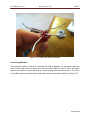
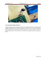
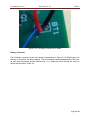
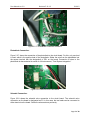
P12412 UV Water Treatment System Safety
Mechanism:
User Manual
Table of Contents:
1. Introduction…………………….…………………………….……….…….…………2
1.1 Background………. ....…...…...………………………………..……….………2
1.2 Acknowledgements ....…...…...………………………………..……….….......2
2. PCB Construction…………………………………………...…...….…….…………3
2.1 Electrical Components……….…..…………………………….…….…………3
2.2 PCB Assembly Instructions..…..……………………………………………….4
3. Valve Construction…………………………………………………….…………..10
3.1 Valve Components………...…………………………………………….........10
3.2 Valve Component Testing…...…………….…………………………………11
3.3 Valve Assembly Instructions…..……………………………………………..11
4. Total System Integration….……………………………………………….……….....…13
5. Troubleshooting…..……..……………………………………………..………......17
5.1 PCB Troubleshooting……....……………………………………….…….......17
5.2 Valve Troubleshooting……...…………….………………………….…..……18
User Manual ver 3.0
Revision 5-21-12
P12412
1. Introduction:
1.1 Background
The purpose of this project is to create a safety mechanism for a UV water treatment system
in Mexico. The safety system is equipped with photo-diodes inside the UV chambers the
measure the amount of UV light being created. Once the UV output falls below a safe value
the PCB will cut power to the irrigation valves (which closes them), while simultaneously
initiating a warn operating system consisting of LEDs and sirens. For the operators
convince during long power outages the PCB is equipped with switches to deactivate the
sirens until the supply of power returns. Also to prevent any accidental water contamination
there are ball valves located before the irrigation valves for manual shutoffs of the fluid
system. These valves will be opened when the bulbs are able to sterilize the water.
The following sections will explain all the electrical components and the process to construct
the PCB. Also there will be instruction on how to integrate the photo-diodes and the valve
system into the UV water treatment kiosk system. The last sections list common problems
and troubleshooting technics for the operator.
1.2 Acknowledgements
Client:
Foundation:
MSD Guide:
MSD Team:
Fermin Reyegadas
Fundacion Cantaro Azul
Sarah Brownell
Matt Switzer
Phil Floroff
Evan Hall
Tyler Josselyn
Page 2 of 18
User Manual ver 3.0
Revision 5-21-12
P12412
2. PCB Construction:
2.1 Electrical Components
Electrical
Component
Number
(EC #)
# of units
(per
board)
Electrical
Component
Name
Description/Comments
Figure #
1
1
Speaker
Operator warning speaker
2.2.1, 2.2.2
2
3
LED
Amber (1), Red (1), Green (1), LEDs for
various operator messages
2.2.3
3
1
Switch
Operator warning switch
2.2.4
4
1
Power
Connector
Connector for external power supply
2.2.5
5
1
Battery
Connector
Connector for 9V battery
2.2.6
6
1
Photodiode
UV sensitive photodiode
2.2.7
7
1
Solenoid
Solenoid valve connection to board
2.2.8
Page 3 of 18
User Manual ver 3.0
Revision 5-21-12
P12412
2.2 PCB Assembly Instructions
Figure 2.2.1: Polarity of Speaker
Figure 2.2.2: Leads Connected to Speaker
Page 4 of 18
User Manual ver 3.0
Revision 5-21-12
P12412
Connecting Speakers:
Refer to Figure 2.2.1-2.2.3 to see proper connection of speakers to circuit board. Use wire
length of about 5 inches (or about 13 cm). Solder a wire to both of the connections on the
speaker (shown in Figure 2.2.2). When both wires are connected to the speaker, it must then be
connected to the proper spot on the circuit board (labeled LS1 on the circuit board). Mind the
positive and negative terminals of the speaker and make sure that they are connected properly
on the board. The square terminal on the circuit board corresponds to the positive terminal on
the speaker. The circular terminal is negative.
Figure 2.2.3: LED Polarity and Leads Connected
Connecting LEDs:
LEDs are connected similarly to the speakers. Figure 2.2.3 shows the polarity of on LED (the
positive lead is the longer one). Solder a wire to each lead of the LED, and as with the
speakers, solder to the LED slots on the circuit board (labeled LED1, LED2, and LED3). As with
the speaker, the square terminal corresponds to positive, the circular terminal negative. LED
colors are corresponding slots are listed below:
LED1 = Amber/Orange LED, used for low battery indicator
LED2 = Red LED, used to warn operator of failure
LED3 = Green LED, used to indicate that the failure has been resolved
Page 5 of 18
User Manual ver 3.0
Revision 5-21-12
P12412
Figure 2.2.4: Switch with Wires Connected
Connecting Switches:
Connecting the switch is similar to connecting the LED or Speaker. On the switch, there are
holes on the leads where the wires are to be connected. Refer to Figure 2.2.6 to see which
leads on the switch to connect the wires to. These correspond to the slots marked 1, 2, 5 and 6
on the SW1 spot on the circuit board. Solder the wires into these slots as shown in Figure 2.2.7.
Page 6 of 18
User Manual ver 3.0
Revision 5-21-12
P12412
Figure 2.2.5: Power Supply Connector On-Board
Connecting Power Supply Connector:
Connect the power supply connector similarly to the previous instructions. The positive and
negative terminals on the connector are shown in Figure 2.2.5. As with the previous
connections, the square terminal on the board is positive, the circular is negative. Solder the
wires through the holes on the terminals on the connector, then solder the wires into the circuit
board.
Page 7 of 18
User Manual ver 3.0
Revision 5-21-12
P12412
Figure 2.2.6: 9V Battery Connection on Board
Battery Connector:
The 9V battery connector on the circuit board is shown above in Figure 2.2.6. With this part, the
red wire on is positive, the black negative. The circuit board is labeled appropriately in this case
as well, with the positive terminal labeled with a (+). Solder the wires through the holes as
before with the switch, LEDs, etc.
Page 8 of 18
User Manual ver 3.0
Revision 5-21-12
P12412
Figure 2.2.7: Photodiode Connection on Board
Photodiode Connection:
Figure 2.2.7 shows the connection of the photodiode to the circuit board. For this, only one lead
is used, which is the positive lead of the photodiode. Solder the wire from the photodiode into
the square terminal with the designation of PD1 on the board. Connection of wires to the
photodiode is demonstrated in section 4 of this document, “Total System Integration.”
Figure 2.2.8: Solenoid PCB Connection
Solenoid Connection:
Figure 2.2.8 shows the solenoid valve connection to the circuit board. The solenoid valve
connection on the board is designated as P2. In this case, the two leads can be connected to
either terminal on the board. Solder the wires as done previously.
Page 9 of 18
User Manual ver 3.0
Revision 5-21-12
P12412
3. Valve Construction:
3.1 Valve Components
Valve Part
Number
(VP #)
# of
units
Valve Part
Name
Description/Comments
Figure #
1
2
Ball Vale
½ inch PVC Ball Valve
Figure 3.1.1
2
2
Irrigation
Valve
Electro-Mechanical Safety Valve, The
interface between the PCB and the water
flow system
Figure 3.1.2
Important Parts of the Irrigation Valve
3
2
Solenoid
Electric Magnet, controlled by PCB
Figure 3.1.3
4
2
Solenoid
Piston
Opens when power is supplied, Spring
loaded to close when power is cut
Figure 3.1.3
5
2
Valve Head
6
2
Diaphragm
Spring
Top of valve, remove bolts to access the
valve internals
Applies sufficient additional pressure to
close valve
5
2
Diaphragm
Valve seal
Figure 3.1.3
6
2
Valve Block
Bottom of valve, fixed to water flow system
Figure 3.1.3
Figure 3.1.3
Figure 3.1.3
Page 10 of 18
User Manual ver 3.0
Revision 5-21-12
P12412
3.2 Valve Component Testing
VP #
Description of how to test valve parts
Spec
Units
Nominal
Value
1
Rotate handle clockwise to close, (Handle is
perpendicular to pipe flow); Rotate handle counterclockwise to open, (Handle is parallel to pipe flow)
NA
Handle
Rotates
2
Test the manual open leaver, Same orientation as VP 1
NA
Leaver
Rotates
Actual
Value
Important Parts of the Irrigation Valve
3
Apply 12v power supply to see if magnet activates
NA
4
After power is supplied to piston retracts, power is cut
piston spring ejects piston
NA
5
Bolts can be removed
NA
6
Spring can be compressed
NA
7
Diaphragm is flexible
NA
8
Can sufficiently connected to pipe system, without leaks
NA
Electrical
Field is
Created
Piston
Moves
Head
detaches
Spring
flexes
Diaphragm
fits inside
valve
No leaks
3.3 Valve Assembly Instructions
1. Each UV chamber will get its own valve system.
a. Each system consists of an irrigation valve and a ball valve
2. The irrigation valves should be pre-assembled by the manufacture prior to installer
receiving them.
3. The ball valves can be found at any local distributer or hardware store in the plumbing
section.
4. The ball valve is located at the irrigation valve inlet.
a. The proper orientation of the irrigation valve is given by flow directional arrows
located on the connection points for the valve, see Figure 3.3.1.
5. The two valves can be connected in a number of ways with various pipe fittings.
a. The important thing that the installer should remember is to use the least number
of fittings that will allow the two valves to be located as close as possible.
i. Least number of fittings is to reduce cost and potential leakage points.
ii. The close proximity to the irrigation valve is to reduce the volume of
contaminated water between the valve and the UV chamber.
Page 11 of 18
User Manual ver 3.0
Revision 5-21-12
P12412
Figure 3.3.1
Most kiosks will consist of multiple UV chambers. Figure 3.3.2, illustrates how two chambers can be
piped together. The inlet is on the left, it is from the contaminated water reservoir on the roof of the
kiosk. The water is piped down to a “Tee” pipe fitting. Each side of the “Tee” pipe fitting will lead to a
valve system. The valve system has, in series, a ball valve followed by an irrigation valve. Once the
water exits the valve system it then ascends to the two UV chambers, which are located to the right,
outlet side, of Figure 3.3.2. If additional UV chambers are to be installed inside a kiosk; a separate valve
system will be required in series for each chamber.
Figure 3.3.2
Page 12 of 18
User Manual ver 3.0
Revision 5-21-12
P12412
4. Total System Integration:
At this point the PCB and the Valve System should be assembled and now they should be
integrated in to existing and new UV water treatment systems.
1. The first part that needs to be assimilated into the existing
design is the valve system.
2. The valve system should be located at the inlet of each UV
chamber.
3. Figure 4.1 illustrates the current technique used to pipe the
contaminated water supply into the UV chambers.
a. There is a single “T” pipe fitting that splits the water flow
and directs it to each chamber.
b. To integrate the valve systems into the UV water
treatment system, this “T” should be moved farther back
with respect to the flow of water.
c. The overall integration should consist of the water separating “T”, followed by the
valve systems then direct connections to their respective UV chambers.
i. The valve systems should be connected as close as possible and with the
least number of fittings.
1. This will reduce cost and potential leakage points.
2. Also the volume of water, in the pipe, between the valve system
and the UV chamber will flow into the chamber even after a failure
has occurred. Therefore this volume should be minimized.
a. The water that is drained will displace the already sterilized
water near the exit of the chamber.
d. If there are additional UV chambers required in the kiosk, then this process
should be repeated for each chamber.
e. When the valve systems are installed they should be installed in an orientation
that allows for easy operator access.
i. The easy access should allow access to the solenoid’s wires and removal
of the solenoid and head from the block of the irrigation valve.
ii. This allows any valve maintenance that could be necessary to repair the
valve system.
4. The next part of the safety system that should be installed is the PCB and all associative
subassemblies.
5. The electrical housing is
a junction box; see
Figure 4.2: left side,
which should be located
at any local hardware
store.
6. The PCB should be set
inside the junction box.
Page 13 of 18
User Manual ver 3.0
Revision 5-21-12
P12412
a. Marks should be made on the inside of the box for all of the operator interfaces.
i. This includes the LEDs, switches, speakers, wire leads and power
connections.
b. Then the PCB should be removed to allow for the proper holes to be drilled.
i. The proper hole diameters to be drilled will allow the respective operator
interface object to fit into it, but not too large to allow foreign agents to
enter the box, such as bugs or excess moisture.
c. Once the holes are drilled, the PCB should be reinstalled followed by installation
of all the operator interface components, see Figure 4.2: right side.
i. Electrical tape should be placed along the bottom surface of the PCB,
covering the leads which go through the board.
ii. If the operator interface components loosely fit inside the housing holes
then electrical tape or cocking should be used to secure them in place.
iii. The PCB should then be taped and secured to the bottom of the junction
box.
d. The 9 volt battery should now be connected to its connector
e. Flip the switch so that the red LED is ON and the speaker is sounding. This
means that the alarm system is working. If this does not happen with the switch
in either position, check the troubleshooting portion of this document.
f. The top of the housing should be attached to the junction box.
7. The junction box should now be mounted somewhere in the kiosk that allows for easy
operator access and maximizes operators awareness.
a. This will allow the operator to have full access to the control board.
b. The position should be in a location that will grasp the attention of the operator(s)
as long as they are either inside or outside, but still close proximity, to the kiosk.
8. At this point the photo-diode should be installed in all of the UV chambers.
9. The photo-diodes should be connected to wire leads by the use of inline crimps, see
Figure 4.3. The positive lead of the photodiode is the lead which is on the same side as
the tab (which can be seen in Figure 4.3 below).
Page 14 of 18
User Manual ver 3.0
Revision 5-21-12
P12412
a. Holes should be made inside the UV chambers about in the center of the
germicidal bulb location.
b. To allow clearance between the bulb and the photo-diode the actual hole should
be located slightly to the side of the bulb, see Figure 4.4, illustrates the location
of the UV bulb inside the chamber and the photo-diode position.
i. This will allow the photo-diode to have better exposure to the germicidal
bulb.
c. The inline crimps, see Figure 4.3: Blue Crimps, should be secured to the
stainless steel siding of the UV chamber through the use of a single piece of duct
tape.
i. This will prevent the photo-diode from being dislodged form the chamber
while proper positioning is done.
1. The photo-diode should be directed directly at the germicidal bulb.
ii. Once the correct orientation is
found more duct tape should
be applied to the inline crimps
to solidify the location.
d. The chambers should be reassembled
and reinstalled in the kiosks.
10. At this point all proper wire leads should be
connected, see Figure 4.5.
a. The connection include the PCB to the
irrigation valve solenoid and the PCB
to the photo-diode
b. The wires should be connected using
disconnects that are either crimped on
or wire nuts will work too. Either way
all wire connects should be sufficiently wrapped in electrical tape for operator
safety.
11. The system should then be tested to make sure there is full functionality in the safety
system
a. Make sure the UV light is on. If on, the green LED should be ON, meaning that
the system is working and the valve is open, allowing water to flow. Check that
water is flowing.
b. Flip the switch to the other position, the green LED
should be OFF.
c. Shut off the UV light source. The speaker should
sound and red LED should turn on. Check that the
water flow has been cut-off. If so, the system is up
and running correctly.
Page 15 of 18
User Manual ver 3.0
Revision 5-21-12
P12412
Operator Alert System Functionality:
There is an alarm/alert system as previously mentioned used to warn the operator that there
has been a failure and water flow has been cut-off. The alarm/alert system consists of a red
LED and high pitched speaker. When a failure occurs, the red LED turns ON and the speaker
will sound. When the operator hears or sees this alert, they can then flip the switch. This will
shut off the speaker and LED. In order to alert the operator that the system is running again, a
green LED will turn on. The switch should then be flipped back to its original position so that the
speaker and red LED will operate as before when a failure occurs, see Figure 4.7.
To insure that there is no contamination during a failure the operator should close the ball valve
located in the valve system as soon as they see the red LED and/or hear the siren. This is a
manual interface that will ensure that the water cannot flow through the system. At this point the
operator can deactivate the siren and red LED via the switch. At the time the operator sees the
green LED they should beginning timing. The timing should be anywhere from 5 to 10 minutes
depending on the specified bulb warming up time that is instructed with these bulbs. As long as
the green LED stays illuminated during this time the operator
can reactivate the warn operator system by moving the switch
to the previous location. As long as the warn operator system
trigger it is safe for the operator to reopen the ball valve in the
valve system.
Whenever the warn operator system is triggered the ball valve
should remain closed. Also as part of nightly shutdown the ball
valve should be closed to prevent any contamination. The ball
valve closed orientation can be seen in Figure 4.6
Page 16 of 18
User Manual ver 3.0
Revision 5-21-12
P12412
5. Troubleshooting:
5.1 PCB Troubleshooting
#
Description of
Problem
Description of Solution
Actual Value
Step 1) Verify connection of speaker and LED on circuit board
1
Speaker and red
LED not operating
2
Green LED fails to
illuminate
Step 2) Check the polarity of the connections (remember square terminal is
positive and on all LEDs the longer lead is positive)
NOTE: If polarity is wrong, remember current position and flip part
around
Step 3) Check the solder connection on the board and on the part. Make
sure there is enough solder and adequate connection is made at the part /
board interface.
NOTE: If there is not enough solder, add more solder. Be mindful to not
bridge connections on the board or the part. Add enough solder so that
you are comfortable that a good connection has been made
OVERALL NOTE: Insufficient solder on any interface location could result
in overall system failure.
Follow the same steps as previous failure
Step1) Check connection between solenoid and PCB wire leads.
3
Failed connection
between PCB and
Solenoid
Step 2) Check connection between PCB solenoid wire leads on PCB.
Step 3) Check that solenoid is still responsive.
NOTE: Connect direct controllable power supply to solenoid, to simulate
system activation to see if solenoid response.
Step 4) If solenoid fails to respond to sufficient power supply; replace
solenoid.
Step 1) Check that power supply is plugged into PCB
4
Control PCB fails
to respond or
activate
Step 2) Check that power supply is plugged into outlet and that power cord
is connected to transformer brick.
Step 3) Check that power is supplied to kiosk
Page 17 of 18
User Manual ver 3.0
Revision 5-21-12
P12412
5.2 Valve Troubleshooting
#
Description of
Problem
Description of Solution
Actual Value
1
Leakage between
valve and pipe
connection
Apply “Teflon Tape” or other similar sealant to fittings and sufficiently
tighten
2
Leakage between
head and block
Step 1) Align diaphragm properly: there is a small notch in the block that
a key on the diaphragm fits into
Step 2) Tighten the four bolts that secure the head to the block
Step 1) Remove the four bolts and the valve head
Step 2) Clean diaphragm with clean water and rag
3
Valve fails to seal
Step 3) Flush system with water by opening manual valve, (Make sure
and activate UV chamber first or manually close system between irrigation
valve and UV chamber to prevent contamination of clean water)
Step 4) Re-assemble valve
4
Solenoid leaks
Make sure solenoid is inserted correctly and tighten
Step 1) Close manual ball valve
Step 2) Remove the four bolts and the valve head
5
Upper reservoir
empties when
valve should be
closed
Step 3) Clean diaphragm with clean water and rag
Step 4) Flush system with water by opening manual valve, (Make sure
and activate UV chamber first or manually close system between irrigation
valve and UV chamber to prevent contamination of clean water)
Step 5) Re-assemble valve
6
Ball valve will not
close
7
Solenoid fails to
activate
Replace ball valve
Step 1) Check wire connects between solenoid and PCB
Step 2) If that doesn’t work, replace solenoid
Page 18 of 18