1
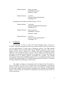
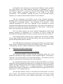
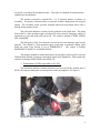
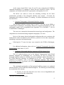
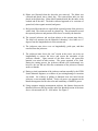
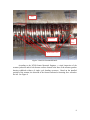
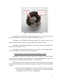
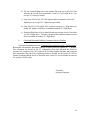
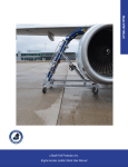
NATIONAL TRANSPORTATION SAFETY BOARD
Office of Aviation Safety
Washington, D.C. 20594
Horizontal Stabilizer Trim Actuator Factual Report
June 5, 2014
A.
B.
ACCIDENT
DCA12RA025
Location:
Date:
Time:
Aircraft:
70 nm South of Monterrey, Mexico
December 9, 2012
About 0932 UTC
Learjet 25, N345MC
ATTENDEES
Accident Site Documentation, December 11 - 14, 2012:
Chairman:
Captain Jorge Garcia Gallegos
DGAC-Mexico
Mexico City, Mexico
Technical Advisor:
Tom Jacky
National Transportation Safety Board
Washington, D.C.
Technical Advisor:
Jimmy Avgoustis
Bombardier Aerospace
Montreal, Canada
Technical Advisor:
Eric West
Federal Aviation Administration
Washington, D.C.
Examination at the NTSB, September 16 - 20, 2013:
Chairman:
Captain Oscar Chapa Rivera
DGAC-Mexico
Mexico City, Mexico
Member:
Capt. Fermin Leon Gonzalez
Colegio de Pilotos Aviadores de Mexico, A.C
Technical Advisor:
Michael Bauer
National Transportation Safety Board
Washington, D.C.
1
Technical Advisor:
Jimmy Avgoustis
Bombardier Aerospace
Montreal, Canada
Technical Advisor:
Eric West
Federal Aviation Administration
Washington, D.C.
Examination and Teardown at NTSB, February 20, 2014:
C.
Technical Advisor:
Tom Jacky
National Transportation Safety Board
Washington, D.C.
Technical Advisor:
Jimmy Avgoustis
Bombardier Aerospace
Montreal, Canada
Technical Advisor:
Eric West
Federal Aviation Administration
Washington, D.C.
SUMMARY
On December 9, 2012, at about 0332 Central Standard Time, a Learjet 25,
N345MC, crashed in mountainous terrain at an elevation of about 5,600 feet above mean
sea level approximately 70 miles south of Monterrey, Mexico. The flight departed
General Mariano Escobedo International Airport (MMMY), Monterrey, Neuvo Leon,
Mexico at 0319 and was enroute to Lic. Adolfo Lopez Mateo International Airport
(MMTO), Toluca, Estado de Mexico, Mexico. The two flight crew members and five
passengers were fatally injured and the aircraft was destroyed. The Dirección General de
Aeronáutica Civil of Mexico (DGAC) investigated the accident. The National
Transportation Safety Board (NTSB) designated a U.S. Accredited Representative under
the provisions of International Civil Aviation Organization (ICAO) Annex 13 as the State
of Design, Manufacture and Registry of the aircraft.
The airplane wreckage was documented at the accident site from December 11,
2012 to December 14, 2012 by the United States team, Bombardier, and technical
advisors for the airworthiness aspects (structure, systems, powerplants). During that time
the horizontal stabilizer actuator assembly components were identified by the technical
advisors, removed from the accident site, documented, and retained by the DGAC for
further examination.
2
On September 16th, 2013 pieces of the horizontal stabilizer actuator assembly
were hand-carried to the NTSB Materials Laboratory in Washington, D.C. by a
representative of the DGAC. The pieces of the horizontal stabilizer actuator assembly
were among multiple components hand-carried to the NTSB by the DGAC
representative. The components, including the pieces of the horizontal stabilizer
assembly, were visually examined with no destructive tests conducted.
After the examination at the NTSB, several of the examined components,
including 2 pieces of the horizontal stabilizer actuator, were shipped to Varian Medical
Technologies in Lincolnshire, Illinois. From September 26 to November 7, 2013
computed tomography (CT) scans were conducted on the components to provide
information about their internal state and configuration. The results of the studies were
provided to the NTSB and technical advisors from the United States. Following the
studies, the components were returned to the NTSB.
The US technical advisors met at the National Transportation Safety Board
Materials Laboratory in Washington, D.C. on February 20, 2014 to examine and
disassemble the horizontal stabilizer jackscrew assembly removed from the accident site.
The horizontal stabilizer jackscrew pieces examined were the jackscrew assembly
with the upper attachment point to the horizontal stabilizer and a piece comprised of the
gear box housing and the jackscrew interface.
The NTSB laboratory examination of the horizontal stabilizer trim actuator failure
fracture surfaces exhibited evidence of single cycle bending overstress. No evidence of preexisting damage, corrosion or fatigue was noted in the examined components.
D.
DETAILS OF THE EXAMINATION
1. Description of the Horizontal Stabilizer Actuator
The Horizontal Stabilizer Actuator provides longitudinal (pitch) trim of the
airplane by controlling the angle of incidence of the horizontal stabilizer. The actuator is
connected to the forward portion of the horizontal stabilizer. The bottom end of the
actuator is connected to the forward spar of the vertical stabilizer.
By extension and retraction of the actuator, the horizontal stabilizer is moved up
and down to provide longitudinal (airplane nose up or airplane nose down) trim. For this
airplane, the fully-extended position of the actuator corresponds to a horizontal stabilizer
leading edge (full) up position of 1°-1.5° (airplane nose down). The fully-retracted
position of the actuator corresponds to at horizontal stabilizer leading edge full down
position of 8°7’-8°30’ (airplane nose up).
The horizontal stabilizer actuator is electrically driven and includes a screwjack
type of actuator. The mechanical screwjack portion of the actuator is located in a sealed
housing and includes the screw, gears, bushings, and bearings. Over rotation of the
3
screwjack is prevented by mechanical stops. The stops are installed in both directions –
airplane nose up and down.
The actuator screwjack is operated by 1 of 2 electrical motors, a primary or
secondary. The primary electrical motor can operate at either a high-speed or low-speed
setting. The secondary motor provides autopilot pitch trim movements and is also a
backup for the primary motor.
The pitch trim indicator is located on the pedestal in the flight deck. The pitch
trim switch is a three-position toggle switch used to select normal, emergency modes of
operation or to turn the pitch trim system off. The switch is marked P TRIM, NORM,
OFF, and EMER.
The Emergency Pitch Trim Switch is located on the trim indicator panel on the
pedestal. The switch is a three-position toggle switch used to manually change pitch
when the pitch Trim Switch is set to EMERGENCY. The switch is marked
EMERGENCY NOSE UP, and NOSE DOWN.
The primary method to control pitch trim is by the pilot’s and co-pilot’s trim and
TRIM Arming Switch, located on each control wheel in the flight deck. These pitch trim
switches are marked NOSE DOWN and NOSE UP.
2. Examination at NTSB, September 16-20, 2013
The horizontal stabilizer actuator jackscrew was recovered at the accident site by
DGAC investigators during the on-scene portion of the investigation. See Figure 1.
Figure 1 - The Horizontal Stabilizer Actuator, jackscrew segment, in its found location at accident site
(Photograph courtesy of the DGAC).
4
On September 16, 2013 the DGAC investigator arrived at the NTSB Materials
Laboratory with various accident airplane components for further inspection. The
components were unpacked, sorted and labeled. Fourteen (14) component sets were
identified and photographed. Included were 3 components from the horizontal stabilizer
actuator assembly.
For the examination, the following horizontal stabilizer actuator assembly
identification was used (See Figure 2):
2A – Is the jackscrew assembly and one attachment point. This attachment point
connects the actuator assembly to the horizontal stabilizer.
2B – Is one of the actuator motors. The actuator motor is approximately 5 inches
long and 2 inches in diameter. The actuator design contains two motors, only one motor
was present at the inspection. Note: this segment was not retained following the
September, 2013 examination; the segment was returned to the DGAC, and therefore not
examined during this activity.
2C – Is one of the attachment points, the gear box housing and the jack screw
interface. This attachment point connects the actuator to the vertical stabilizer. The
jackscrew and tie rod were fractured adjacent to the gearbox. The gearbox housing plate
was bent and 1 bolt was sheared from the attaching hole.
2C
2B
2A
.
Figure 2 - Pieces of the horizontal stabilizer actuator, as received.
Attempts to X-ray the component using the Materials lab X-ray machine were
unsuccessful.
5
At the request of the DGAC, items 2A and 2C were retained by the NTSB for
computed tomography (CT) scanning at a future date (See Section D.3 below). The 2B
component was returned to the DGAC representative on September 20, 2013.
The DGAC was asked to review the remaining wreckage for the linear
potentiometer assembly of the Horizontal stabilizer trim actuator. If located, the
component will be subject to further CT scanning. No further information was received
from the DGAC.
3. Computed Tomography of Horizontal Stabilizer Actuator
The horizontal stabilizer actuator items 2A and 2C were sent, by the NTSB, to
Varian Medical Technologies, Lincolnshire, Illinois for computed tomography (CT). The
radiographic studies were accomplished from September 26 to November 7, 2013 at
Varian Medical Technologies.
The items were examined to document their internal state and configuration. The
components were documented using computed tomography (CT) scans.
Review of the images showed radiographic indications that were consistent with
small particles in the area adjacent to the jackscrew, particles in a few other components,
and damage consistent with impact damage.
Following the CT scans, the items were returned to the NTSB in Washington,
D.C.
For additional information, please refer to Computed Tomography Specialist’s
Factual Report, dated March 13, 2014.
4. Teardown of Horizontal Stabilizer Actuator at NTSB, February 2014
The U.S. technical advisors met 1 at the National Transportation Safety Board
Materials Laboratory in Washington, D.C. on February 20, 2014 to examine the
horizontal stabilizer jackscrew assembly previously examined (without disassembly) at
the NTSB Materials Laboratory on September 16-20 2013. The examination was
conducted in accordance with a test plan (Horizontal Stabilizer Trim Actuator
Examination Test Plan), developed by the NTSB and approved by the attendees prior to
the start of the examination.
The examination and teardown of the horizontal stabilizer actuator was conducted
with the assistance of an NTSB Senior Materials Engineer. The following was noted during
the examination of the actuator:
a) On piece 2A, the outer dust tube cover sleeve was cut longitudinally and
removed from the actuator body.
1
The DGAC was invited but did not attend.
6
b) Debris was liberated when the dust tube was removed. The debris was
collected and placed into a plastic bag. The removed dust tube was also
placed in the plastic bag. Some debris remained inside the dust tube, at the
crushed end of the tube. The debris collected appeared to be a mixture of
ground soil, other organic material, and grease.
c) Red, grease-like material was wiped off the exposed section of the jackscrew
with a cloth. The cloth was saved in a plastic bag. The red material covered
the exposed jackscrew and portions of the sleeve covered by the dust tube.
d) The exposed jackscrew rod was bent relative to the actuator inner sleeve.
The bend was measured on the Materials Laboratory’s level table as 6-7
degrees from the longitudinal axis of the actuator rod.
e) The jackscrew outer sleeve was cut longitudinally, pried open, and then
removed from the jackscrew.
f) The jackscrew inner sleeve (the “nut” section to the screw) was twice cut
longitudinally to remove the sleeve and expose the remainder of the
jackscrew threads. Upon removal of the inner sleeve, red grease-like
material was noted in both sections. The grease appeared to be fresh.
During the cutting process, the jackscrew threads were inadvertently cut;
however, the cuts did not affect the examination of the jackscrew fracture
surface or threads.
g) During a visual examination of the jackscrew and nut assembly by the NTSB
Senior Materials Engineer, no evidence of pre-existing damage or corrosion
was noted. No evidence of galling or abnormal wear was noted on the
jackscrew or nut assembly threads. Fresh, red grease was apparent on the
threads that appeared to have the color and consistency of Mobil 28 grease.
h) Using computer imaging measurement software, the distance between the
threaded jackscrew end stop and the end of the threaded section of the inner
sleeve was measured as 0.96 – 0.98 inches. See Figure 3.
7
Nut
Jackscrew
End
Stop
Inadvertent Cuts
Figure 3 - Jackscrew Thread Measurement.
According to the NTSB Senior Materials Engineer, a visual inspection of the
actuator jackscrew and tie bolt fracture surfaces located at the base of the actuator gearbox
housing exhibited evidence of single cycle bending overstress. Based on the installed
position of the actuator, the direction of the fracture indicated a fracturing force aft and to
the left. See Figure 4.
8
Tie Bolt
Jackscrew
Figure 4 - Actuator Jackscrew Fracture Surface.
According to the NTSB Senior Materials Engineer, the 6-7 degree bend of the
jackscrew thread was not in the same direction as the bending overstress.
According to the NTSB Senior Materials Engineer, the actuator’s inner tie rod
exhibited visual evidence of extensive yielding adjacent to the fracture surface.
According to the Senior Materials Engineer, the fracture surfaces on component 2C
matches the fracture surfaces of 2A.
According to the Senior Materials Engineer, no evidence of pre-existing damage,
corrosion or fatigue was noted in the examined components.
5. Maintenance Records Related to the Horizontal Stabilizer Actuator
Bombardier provided an electronic copy of the Learjet 25 Service Manual.
According to the manual item number Q2740021, the Horizontal Stabilizer Actuator must
be removed and overhauled each 600 flight hours. (See Attachment 1).
The DGAC provided an electronic copy of the N345MC airframe log. From the log
the following information was determined regarding the airplane’s Horizontal Stabilizer
Actuator:
a) Duncan Aviation overhauled the stab trim actuator for the accident aircraft in
June 2005 (See Attachment 2). At the time, the accident aircraft had
accumulated a total of 10,559 (ACTT) flight hours.
9
b) The last recorded flight time in the airframe log book was in July 2012 and
indicates the aircraft had accumulated a total of 11,056 flight hours. (An
average of 7 hours per month).
c) From June, 2005 to July, 2012 the airplane had accumulated a total of 497
flight hours, an average of 5.9 flight hours per month.
d) From July 2012 to December 2012, using an average of 5.9 flight hours per
month, the airplane would have accumulated another 29.5 flight hours.
e) Estimated flight time of the overhauled stab trim actuator at time of accident
was 526.5 flight hours. Therefore, the horizontal stabilizer actuator was not
due for overhaul for another 73.5 flight hours.
6.
Calculated Horizontal Stabilizer Actuator Jackscrew Position
Using the information from the Computed Tomography Specialist’s Factual Report,
Bombardier calculated the horizontal stabilizer actuator jackscrew position as 1.17 degrees.
The calculation was based on the CT radiographic study that indicated the jackscrew
position was averaged to be 0.995 inches from its fully-extended position, and compared
that information from the fully extended position as detailed on the Learjet 25 Service
Manual, assuming that the travel as described in the Learjet 25 Service Manual is based on
the actuator’s electric stops.
Tom Jacky
Aerospace Engineer
10