1
DOCUMENTATION OF COMPUTER PROGRAM PACKAGE
FOR STRUCTURE / PILE / SOIL
INTERACTION ANALYSIS
Program:
SPLICE
Report:
MAINTENANCE MANUAL
Date:
1 July 1994
Report 8407 - 3
Revision
Revision
Revision
Revision
0
1
2
3
10
17
01
01
February 1980
November 1984
June 1989
July 1994
───────────────────────────────────────────────────────────────────
Date: 1 July 1994
Report: SPL-MM
Page:
0.1
───────────────────────────────────────────────────────────────────
DOCUMENTATION OF COMPUTER PROGRAM PACKAGE FOR
STRUCTURE/PILE/SOIL INTERACTION ANALYSIS
The present report contains the Maintenance Manual for program
SPLICE.
The SPLICE package consists of the following independent computer
programs :
SPLICE :
GENSOD :
Solves combined structure/pile/soil system
Generates soil data needed by SPLICE
PILGEN :
Generates pile data needed by SPLICE
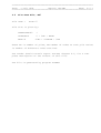
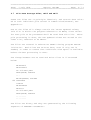
The documentation of the package has been presented in the following reports :
┌─────────────────────────────┬──────────┬──────────┬──────────┐
│ Program
│ SPLICE │ GENSOD │ PILGEN │
╞═════════════════════════════╪══════════╪══════════╪══════════╡
│
│
│
│
│
│ General Description
│ SPL-GD │ GEN-GD │
│
│
│
│
│
│
│ User's Manual
│ SPL-UM │ GEN-UM │ PIL-UM │
│
│
│
│
│
│ Maintenance Manual
│ SPL-MM │ GEN-MM │
│
│
│
│
│
│
│ Engineering Documentation
│ SPL-ED │ GEN-ED │
│
└─────────────────────────────┴──────────┴──────────┴──────────┘
Test examples with complete input/output files have been presented
in report SGP-EX.
Program SPLICE was developed as a joint project between Aker Engineering A/S and the Norwegian Geotechnical Institute, with support
from the Royal Norwegian Council for Scientific and Industrial
Research (NTNF) and Det norske Veritas. Mr. Carl J. Frimann
Clausen acted as a consultant to the project group. His report
9302-1 presents the results from a program verification study.
───────────────────────────────────────────────────────────────────
Date: 1 July 1994
Report: SPL-MM
Page:
0.2
───────────────────────────────────────────────────────────────────
───────────────────────────────────────────────────────────────────
Date: 1 July 1994
Report: SPL-MM
Page:
0.3
───────────────────────────────────────────────────────────────────
TABLE OF CONTENTS
1.0
INTRODUCTION
2.0
GENERAL SYSTEM DESCRIPTION
3.0
GENERAL PROGRAM DESCRIPTION
4.0
DATA
4.1
4.2
4.3
4.4
4.5
4.6
FILES DESCRIPTION
Master Control Data File, NF5 and NF26
Pile Data File, NF7
Structure Reduced Stiffness Matrix File, NF8
Interface Load Vector File, NF9
Soil Data File, NF10
Mindlin Interaction Values File, NF11
4.7
4.8
4.9
4.10
4.11
4.12
Pile Data Storage Files, NF12 and NF13
Print File, NF14
Interface Solution/Pile Solutions, NF15
User Terminal, NF16
Re-Start Values, NF17
Scratch Files, NF18 and NF19
5.0
CONTROL FLOW
6.0
PROGRAM LIMITATIONS
7.0
ERROR MESSAGES
8.0
BUILT-IN TRACE OPTIONS
8.1 Interface Vector/Matrix Trace
8.2 Single Pile Head Trace
8.3 Full Pile Head Trace
8.4 Full Pile Head Stiffness Trace
8.5 Control Flow Trace
8.6 Nodal Point Trace
8.7 Full Element Trace
9.0
FUTURE MODIFICATIONS
10.0 IMPLEMENTED MODIFICATIONS
APPENDIX A :
COMMON BLOCK DESCRIPTION
───────────────────────────────────────────────────────────────────
Date: 1 July 1994
Report: SPL-MM
Page: 1.0.1
───────────────────────────────────────────────────────────────────
1.0
INTRODUCTION
The present report is part of the documentation of a package of
computer programs developed in order to analyze the interaction
between a linear superstructure and its non-linear piled foundation
system for static loading conditions. The package consists of a
soil data generator (GENSOD), a pile data generator (PILGEN) and
the program solving the combined structure/pile/soil system
(SPLICE).
This report, SPL-MM, presents the maintenance manual for program
SPLICE. The report contains information that may be needed for
future program corrections and modifications. If the user needs an
explanation of the methods used, and the assumptions made for the
various calculations, the engineering documentation report SPL-ED
should be consulted.
───────────────────────────────────────────────────────────────────
Date: 1 July 1994
Report: SPL-MM
Page: 2.0.1
───────────────────────────────────────────────────────────────────
2.0
GENERAL SYSTEM DESCRIPTION
Data flow within the computer program package has been shown on
page 0.2. The generator programs GENSOD and PILGEN form a number
of data files (NF7, NF8, NF9, NF10) that are input to program
SPLICE.
Program SPLICE solves the non-linear problem of structure/pile/soil
interaction, and generates a number of output data files (NF11,
NF14, NF15, NF16). During the data processing a number of scratch
files may be needed (NF12, NF13, NF17,NF18, NF19, NF26).
A detailed description of the contents of the various files has
been given or referenced to in Section 4.0, Data File Description.
File opening is carried out at the start of subroutine SPLIC1 at
the beginning of program SPLICE.
The present program SPLICE version operates in double precision (8
bytes in each floating point variable).
───────────────────────────────────────────────────────────────────
Date: 1 July 1994
Report: SPL-MM
Page: 3.0.1
───────────────────────────────────────────────────────────────────
3.0
GENERAL PROGRAM DESCRIPTION
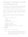
SPLICE is written in FORTRAN-77 and contains approximately 9500
statements including comments. The program consists of a number of
subroutines that use the same common area.
The main program that initiates program execution, is simply:
PROGRAM SPLICE
CALL SPLIC1
STOP
END
Normal run termination, including identified error conditions, is
always through subroutine MSGTIM that terminates by a STOP statement. The present version of SPLICE is intended for use via a
satellite user terminal or a PC, see Chapter 4.10 for modifications
if program is used in batch mode.
SPLICE calls a few system dependant subroutines related to date,
real time and computer time. These calls are done from subroutine
MSGTIM, and the call statements may need to be modified if the
program is installed on new machines.
The SPLICE common block area has been described in Appendix A. The
approximate required size in primary storage for the 32-pile version is:
INTEGER*4
REAL*8
1,200 values
42,500 values
In addition, primary storage must allow local non-dimensioned
subroutine variables, format statements and program instructions.
───────────────────────────────────────────────────────────────────
Date: 1 July 1994
Report: SPL-MM
Page: 3.0.2
───────────────────────────────────────────────────────────────────
SPLICE uses an out-of-core equation solver based on a Cholesky
direct elimination algorithm.
The present program version uses FORTRAN read/write statements for
the binary scratch files. These operations are carried out through
calls to subroutine SPEED. Experience from earlier SPLICE versions
showed that very considerable reduction in required computer time
could be obtained by replacing the FORTRAN read/write statements in
subroutine SPEED by machine dependent I/O routines.
───────────────────────────────────────────────────────────────────
Date: 1 July 1994
Report: SPL-MM
Page: 4.0.1
───────────────────────────────────────────────────────────────────
4.0
DATA FILES DESCRIPTION
SPLICE needs various data files in order to analyze a given problem. They have been indicated on page 0.2. All these files may not
be needed within the same run, this is governed by the master
control input data.
The following pages present a summary of the different files, with
a description of contents and size requirements.
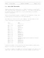
The numerical values of file unit numbers, and the names of the
files connected to these units, are as follows:
UNIT
--------NF5 = 25
NF7 = 7
NF8 = 8
NF9 = 9
NF10 = 10
NF11 = 11
NF12 = 12
NF13 = 13
NF14 = 14
NF15 = 15
NF16 = 6
NF17 = 17
NF18 = 18
NF19 = 19
NF26 = 26
NAME
----------SPLICE.INP
PILE.07
STRUCT.08
LOAD.09
SOIL.10
MINDL.11
SCRATCH.12
SCRATCH.13
SPLICE.RES
INTERF.15
Standard output device (users's screen)
RESTART.17
SCRATCH.18
SCRATCH.19
SPLICE.TMP
Connection between units and files are established by OPEN statements at the start of subroutine SPLIC1.
In order to reduce the number of I/O files needed to be open at the
same time, files are closed after the data needed has been read.
───────────────────────────────────────────────────────────────────
Date: 1 July 1994
Report: SPL-MM
Page: 4.1.1
───────────────────────────────────────────────────────────────────
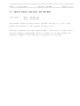
4.1
Master Control Data File, NF5 and NF26
File name :
NF5, SPLICE.INP
NF26, SPLICE.TMP
The reader should consult report SPL-UM, Section 3.0, for a complete description of the content of this file.
The user prepares file NF5 (SPLICE.INP). This file is read, and a
new file NF26 is generated, which is identical to NF5 except for
possible comment lines that may be present in file NF5.
───────────────────────────────────────────────────────────────────
Date: 1 July 1994
Report: SPL-MM
Page: 4.2.1
───────────────────────────────────────────────────────────────────
4.2
Pile Data File, NF7
File name :
PILE.07
File size is given by:
CHARACTER*80
1
INTEGER*4
2 + 3⋅NP + NP⋅NN
REAL*8
15⋅NC + 24⋅NP⋅NN - 3⋅NP
where NP is number of piles, NN number of nodes on each pile and NC
is number of different cross sections.
The reader should consult report PIL-UM, Chapter 4.2, for a complete description of the content of this file.
The file is generated by program PILGEN.
───────────────────────────────────────────────────────────────────
Date: 1 July 1994
Report: SPL-MM
Page: 4.3.1
───────────────────────────────────────────────────────────────────
4.3
Structure Reduced Stiffness Matrix File, NF8
File name :
STRUCT.08
This file contains the reduced (condensed) stiffness matrix for the
superstructure, if the presence of a superstructure (for example a
jacket) was specified.
The file is generated by some program outside the present package,
see page 0.2.
The stiffness values are the forces and moments acting upon the
superstructure at the fixed support points, when these points are
given unit displacements, one freedom at the time.
SPLICE requires that file NF8 has been generated by the following
sequence of statements:
CHARACTER*80 TEXT
DIMENSION NUMHED(32),A(6,192),XYZ(3,32)
.........
REWIND NF8
WRITE(NF8) TEXT,NUMCON
DO 100 N=1,NUMCON
100 WRITE(NF8) NUMHED(N),(XYZ(I,N),I=1,3)
DO 300 N=1,NUMCON
DO 200 J=1,N
..........
J2=6*J
J1=J2-5
200 WRITE(NF8) ((A(I,K),I=1,6),K=J1,J2)
300 CONTINUE
REWIND NF8
In the above statements the values have the following meaning:
───────────────────────────────────────────────────────────────────
Date: 1 July 1994
Report: SPL-MM
Page: 4.3.2
───────────────────────────────────────────────────────────────────
TEXT:
Stiffness file label line. Printed by SPLICE
for identification purposes.
NUMHED:
Pile head numbering sequence corresponding to
the sequence in which the superstructure
stiffness values are given:
NUMHED(1)=Pile head number connected to superstructure support point 1.
NUMHED(2)=Pile head number connected to superstructure support point 2.
......
A:
Superstructure stiffness matrix partition.
Each partition contains 6 rows of the matrix.
Only the lower triangular half, including the
full 6 by 6 submatrix on the leading diagonal,
is stored.
NF8:
FORTRAN unit number, stiffness matrix file.
NUMCON:
Number of structure/pile interface points.
XYZ:
Coordinates for the superstructure support
points.
The size of the file is (J = NUMCON = Number of jacket support
points) :
CHARACTER*80
INTEGER*4
1
1 + J
REAL*8
3⋅J + 36⋅J⋅(J + 1)/2 = 21⋅J + 18⋅J²
───────────────────────────────────────────────────────────────────
Date: 1 July 1994
Report: SPL-MM
Page: 4.4.1
───────────────────────────────────────────────────────────────────
4.4
Interface Load Vector File, NF9
File name :
LOAD.09
The reader should consult report PIL-UM, Chapter 4.3, for a complete description of the content of this file.
The file is generated either by a structure load generator outside
the package described in this report, or the file may be generated
by program PILGEN, see page 0.2.
Several load vectors may be analyzed in the same run. The user is
free to specify if a vector shall have zero as starting point, or
the conditions after last analyzed load vector.
The size of the file is (NP = Number of piles, NV = Number of
vectors) :
CHARACTER*80
NV
INTEGER*4
NV⋅(1 + NP)
REAL*8
NV⋅6⋅NP
In case of several load vectors in the same run, the vectors follow
after each other in the order to be processed. A new label line is
read for each vector. See report PIL-UM, Section 4.3.
───────────────────────────────────────────────────────────────────
Date: 1 July 1994
Report: SPL-MM
Page: 4.5.1
───────────────────────────────────────────────────────────────────
4.5
Soil Data File, NF10
File name :
SOIL.10
The reader should consult report GEN-MM, Section 3.2, for a complete description of the content of this file.
The file is generated by the soil data generator program GENSOD.
The size of this file is given by (N = Number of soil layers):
CHARACTER*80
1
INTEGER*4
2 + 33⋅N
REAL*8
8 + 599⋅N
(+ 125 in case soil displacements are given)
───────────────────────────────────────────────────────────────────
Date: 1 July 1994
Report: SPL-MM
Page: 4.6.1
───────────────────────────────────────────────────────────────────
4.6
Mindlin Interaction Values File, NF11
This file contains the Mindlin interaction values for the different
piles and nodes. These values are used to compute pile/soil/pile
interaction effects, also referred to as pile group effects, and
soil displacements due to specified single point forces.
The values are computed in subroutine MINDL1 in SPLICE, and then
stored on file NF11. The user is free to include these interaction
effects, or to leave them out. Reference is made to report SPL-UM,
Section 3.2. The reader should consult report SPL-ED for theory
and justification.
The file is binary and is generated by the following sequence of
FORTRAN statements (the actual I/O is done through subroutine
SPEED):
DIMENSION IPNT(500),VALINF(3,3,500)
.......
REWIND NF11
DO 900 NP = 1,NPH
DO 800 ND = 1,MAX
IF (NUMELP(NP).EQ.0) GO TO 900
.......
WRITE(NF11) NP,ND,NUMINF
IF (NUMINF.EQ.0) GO TO 800
C
WRITE(NF11) (IPNT(J), J=1, NUMINF)
C
WRITE(NF11) (((VALINF(J,K,L),J=1,3),K=1,3),L=1,NUMINF)
CALL SPEED (.......)
800 CONTINUE
900 CONTINUE
The above values have the following meaning:
NUMINF:
Number of pile elements and single point forces that
interact with node ND located at pile NP. This
number is computed for each node based on given pile
geometry, specified type of interaction (INTER) and
interaction distance (DISTIN).
───────────────────────────────────────────────────────────────────
Date: 1 July 1994
Report: SPL-MM
Page: 4.6.2
───────────────────────────────────────────────────────────────────
IPNT(NE): Pointer for node ND to element and pile numbers
(1 to NE) that interact. For example, if the second
element interacting with a node is located on pile
5, and has element number 4, then:
IPNT(2) = 100 ⋅ 5 + 4 = 504
VALINF(3,3,NE):
Mindlin interaction values, i.e., displacements {DSP} in global x, y, z directions of a point
at location ND due to unit forces {FRC} in global
x, y, z directions at location NE :
{DSP}
=
[VALINF] ⋅ {FRC}
The size of this file is given by (NP = Number of piles, ND =
Number of nodes on each pile, NE = Number of elements interacting
with each node) :
INTEGER*4
NP⋅ND⋅(1 + NE)
REAL*8
9⋅NP⋅ND⋅NE
───────────────────────────────────────────────────────────────────
Date: 1 July 1994
Report: SPL-MM
Page: 4.7.1
───────────────────────────────────────────────────────────────────
4.7
Pile Data Storage Files, NF12 and NF13
These two files are in principle identical, and contain data related to each individual pile stored in common block/PILPRP/, see
Appendix A.
One of the files will always contain the latest updated values,
this file is within the program referred to as NFIN, since values
for next pile to be processed shall be read from this file. After
pile processing is done, the new updated values are stored on the
other file, referred to as NFOUT.
The files are created in subroutine CRNF12 during program SPLICE
initiation. Both files are written here, even if only one is
needed, in order to ensure that sufficient disk space is available
before further processing is done.
The change between use as read and write files is illustrated
below:
NFIN=NF12
NFOUT=NF13
DO 100 NP=1,NPH
READ(NFIN) BUFFER
...
WRITE(NFOUT) BUFFER
100 CONTINUE
I=NFIN
NFIN=NFOUT
NFOUT=I
DO 200 NP=1,NPH
READ(NFIN) BUFFER
.........
.........
The files are binary and they are generated by the following
sequence of FORTRAN statements:
───────────────────────────────────────────────────────────────────
Date: 1 July 1994
Report: SPL-MM
Page: 4.7.2
───────────────────────────────────────────────────────────────────
COMMON /PILPRP/ MATND(51),...,D(50),....
DIMENSION IBUFF(152),BUFF(4822)
EQUIVALENCE (IBUFF(1),MATND(1)),(BUFF(1),D(1))
....
REWIND NF12
DO 100 NP=1,NPH
IF (NUMELP(NP).EQ.0) GO TO 100
....
C
WRITE(NF12) IBUFF,BUFF
CALL SPEED(....,IBUFF,BUFF,...)
100 CONTINUE
It should be noted that common block /PILPRP/ contains both integer
and real values. The meaning of the different values in /PILPRP/
is given in Appendix A. The actual reading/writing is carried out
by subroutine SPEED.
The size requirements for each of the files NF12 and NF13 are (NP =
Number of piles):
INTEGER*4
REAL*8
152⋅NP
4822⋅NP
───────────────────────────────────────────────────────────────────
Date: 1 July 1994
Report: SPL-MM
Page: 4.8.1
───────────────────────────────────────────────────────────────────
4.8
Print File, NF14
This file is generated by program SPLICE as processing proceeds.
The file is formatted for output on a minimum 129 character line
printer.
A description of file content is given in report SPL-UM, Chapter
4.1.
───────────────────────────────────────────────────────────────────
Date: 1 July 1994
Report: SPL-MM
Page: 4.9.1
───────────────────────────────────────────────────────────────────
4.9
Interface Solution/Pile Solutions, NF15
This file may be used to store the structure/pile interface solution (resulting displacements and forces at all pile heads) and/or
the complete pile solutions after a load increment.
The file is generated in subroutine PRT6 if requested by the user.
The complete pile solutions part is identical to files NF12 and
NF13, Chapter 4.7.
The file is generated by the following sequence of FORTRAN statements in subroutine PRT6 :
50
C
C
100
200
300
DIMENSION DSPHDR(32,6),FRCHDR(32,6)
CHARACTER*80 TEXTL
DO 300 NV=1,NUMVEC
IF (NV.EQ.1) REWIND NF15
......
DO 200 INC=1,NUMINC
WRITE(NF15) TEXTL,NV,INC
......
DO 50 NP=1,NPH
WRITE(NF15) (DSPHDR(NP,I),FRCHDR(NP,I),I=1,6)
.....
DO 100 NP=1,NPH
IF (NUMELP(NP).EQ.0) GO TO 100
READ(NFIN) IBUFF,BUFF
WRITE(NF15) IBUFF,BUFF
CALL SPEED (...,NFIN,IBUFF,BUFF,...)
CALL SPEED (...,NF15,IBUFF,BUFF,...)
CONTINUE
CONTINUE
CONTINUE
The above values have the following meaning:
DSPHDR:
FRCHDR:
INC:
Resulting pile head displacements
Resulting pile head forces
Load increment number
───────────────────────────────────────────────────────────────────
Date: 1 July 1994
Report: SPL-MM
Page: 4.9.2
───────────────────────────────────────────────────────────────────
NUMINC:
NV:
NF15:
I:
NP:
NPH:
NUMELP:
NFIN:
IBUFF:
BUFF:
Number of load increments
Load vector number
FORTRAN unit number interface solution file
Counter
Pile number
Number of piles
Number of pile elements on pile NP
File NF12 or NF13, pile data
Pile data, integers
Pile data, real values
───────────────────────────────────────────────────────────────────
Date: 1 July 1994
Report: SPL-MM
Page: 4.10.1
───────────────────────────────────────────────────────────────────
4.10
User Terminal, NF16
This file is generated by program SPLICE as processing proceeds.
The content is displayed at the user's screen. The user may then
check that the run develops normally, and in case not, program
execution can be terminated manually. The various messages that
may be displayed have been described in report SPL-UM, Chapter 4.2.
The file can also be used to obtain different trace values as
processing proceeds. Actions required by the user to obtain trace
output, and a description of the values displayed, have been presented in Section 8 of the present report.
In case the program is used in batch mode, i.e., there is no user
terminal, file NF16 must still be available. Messages will then be
generated to this file, and the user may print the file after run
termination. In that case subroutine SPLIC1 must be modified, i.e.
a file must be assigned to unit NF16 :
NF16 = 16
OPEN (NF16,FILE='SPLICE.16')
───────────────────────────────────────────────────────────────────
Date: 1 July 1994
Report: SPL-MM
Page: 4.11.1
───────────────────────────────────────────────────────────────────
4.11
Re-Start Values, NF17
This file is generated by program SPLICE upon request from the
user, and it contains data that may be used as start values for a
run, rather than zero which would normally be used. The use of
this facility is described in report SPL-UM. The file is written
and read from subroutine RSTART.
File NF17 is in principle generated by the following sequence of
FORTRAN statements (the actual write statements are broken up to
give shorter record length):
COMMON /GLOBAL/ XG(51,100),...
COMMON /PILPRP/ MATND(51),...
DIMENSION IBUFF(152),BUFF(4822)
EQUIVALENCE (IBUFF(1),MATND(1)),(BUFF(1),D(1))
.......
REWIND NF17
REWIND NFIN
WRITE (NF17) TEXT,NPH,(NUMELP(NP),NP=1,NPH)
WRITE(NF17) DSPHDR,FRCHDR,FRCPSI
DO 100 NP=1,NPH
IF (NUMELP(NP).EQ.0) GO TO 100
READ(NFIN) IBUFF,BUFF
WRITE(NF17) DSPRES,DSPINC,SDSP2,FORCER,QPSRES,DSPMAX
100 CONTINUE
The meaning of the different values above has been explained in
Appendix A, Common Block Description.
When re-start values are read from file NF17, program checks that
number of piles (NPH) and number of elements on each pile
(NUMELP(NP) from the pile data file NF7 and the re-start value file
NF17 are identical. If not, an error message is printed and run
execution terminated.
───────────────────────────────────────────────────────────────────
Date: 1 July 1994
Report: SPL-MM
Page: 4.11.2
───────────────────────────────────────────────────────────────────
Re-start values may be fully used (resulting and incremental), or
only partly used (incremental only). Consult report SPL-UM, Chapter 3.2, for further details.
The size requirement for file NF17 is (NP = Number of piles):
INTEGER*4
21
REAL*8
15,600 + 1,722 ⋅ NP
───────────────────────────────────────────────────────────────────
Date: 1 July 1994
Report: SPL-MM
Page: 4.12.1
───────────────────────────────────────────────────────────────────
4.12
Scratch Files NF18 and NF19
These two files are used for storage of interface stiffness values
during solution of interface equations.
File NF18 is generated in subroutine BUILD and contains the resulting superstructure and pile stiffness values, with the lower triangular part of the matrix stored.
File NF19 is generated in subroutine SOLVER and contains the lower
triangular half of the decomposed coefficient matrix.
The size requirement for each of the files NF18 and FN19 is
(J = Number of interface joints) :
REAL*8
36⋅J⋅(J+1)/2
───────────────────────────────────────────────────────────────────
Date: 1 July 1994
Report: SPL-MM
Page: 5.0.1
───────────────────────────────────────────────────────────────────
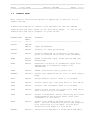
5.0
CONTROL FLOW
Main control flow within SPLICE is explained in Section 3.2 of
report SPL-GD.
A detailed diagram of control flow through the various SPLICE
subroutines has been shown on the following pages. A list of the
subroutines and their purpose is given below.
SUBROUTINE
----------
CALLED
FROM
------
PURPOSE
-------------------------------------------
SPLIC1
SPLICE
(Main)
Input management.
SPLIC2
SPLIC1
Directs all data processing.
SPLIC3
SPLIC2
Directs updating of resulting values and
print of results after each load increment.
READ
SPLIC1
SPLIC2
Reads formatted input files SPLICE.INP and
SPLICE.TMP.
ECHO
SPLIC1
Generates re-print of formatted input file
SPLICE.INP to formatted output file
SPLICE.RES.
LOAD
SPLIC2
Reads load vector data, prints etc.
PRTHED
Several
Prints top identification line on each output
page.
PRT1
SPLIC1
Prints master control data to file NF14.
PRT2
SPLIC1
Prints input soil and pile data to file NF14.
PRT3
SPLIC2
Prints load increment data to file NF14.
PRT4
SPLIC2
Prints trace values for given pile head after
each iteration to file NF14.
PRT5
SPLIC3
Prints incremental and/or resulting pile head
displacements and forces after each load
increment to file NF14.
PRT6
SPLIC3
Prints pile head stiffness values to file
NF14. Stores interface solution and complete
pile solutions on file NF15. Prints pile
solutions with depth to file NF14.
ERROR1
Several
Prints error message to files NF14 and NF16.
───────────────────────────────────────────────────────────────────
Date: 1 July 1994
Report: SPL-MM
Page: 5.0.2
───────────────────────────────────────────────────────────────────
SUBROUTINE
PURPOSE
----------
CALLED
FROM
------
MSGTIM
Several
SOILIN
SPLIC1
Prints various messages related to where
program control is and time values to file
NF16. This routine terminates run execution.
Reads soil data from file NF10.
PILEIN
SPLIC1
Reads pile cross section data from file NF7.
CRNF12
SPLIC1
Reads pile data from file NF7, and creates
pile data files NF12 and NF13.
SPEED
Several
Input/output of binary files.
PILTIP
CRNF12
Computes pile tip stiffness values and
conversion matrices between local and global
coordinate systems.
SOLGRV
CRNF12
Computes initially specified soil displacements, if any, of the soil volume surrounding
each node. Computes pile element gravity
type loading.
INTPL3
SOLGRV
Computes soil displacements by linear
interpolation.
MINDL1
SPLIC1
Computes Mindlin interaction (influence)
values for all piles and nodes and stores
values on file NF11.
MININF or
MINDSP
MINDL1
Computes interaction values from Mindlin's
formulas.
ZERJAC
SPLIC1
LOAD
Zeroes resulting interface values.
Reads superstructure data and checks
coordinates.
RSTART
LOAD
Reads or writes re-start values on file NF17.
RELDSP
SPLIC2
Computes expected relative displacements
pile/soil to be used to find new pile/soil
stiffness values.
MINSUM
RELDSP
Computes displacements of the soil volume
surrounding a node by summation of Mindlin
interaction values times pile element/soil
forces.
STIFF
RELDSP
Computes secant stiffnesses axially and
laterally between pile and soil to be used
for present iteration.
-------------------------------------------
───────────────────────────────────────────────────────────────────
Date: 1 July 1994
Report: SPL-MM
Page: 5.0.3
───────────────────────────────────────────────────────────────────
SUBROUTINE
----------
CALLED
FROM
------
PURPOSE
-------------------------------------------
HEADST(NP,1) SPLIC2
Computes pile head stiffness matrix and load
correction vector for pile NP.
HEADST(NP,2) SPLIC2
Solves pile NP when pile head displacements
are known. Checks for numerical instability.
AXSLV
HEADST
Solves pile axially for given pile tip axial
displacement.
TORSLV
HEADST
Solves pile for torsional rotations and
moments for given pile tip rotation.
LATSLV
HEADST
Solves pile laterally (two directions) for
given pile tip lateral displacements.
INV4
HEADST
Computes the inverse of a 4 by 4 matrix.
CONSTF
HEADST
Converts pile head stiffness matrix and load
correction vector from local to global coordinate system.
MULT6
CONSTF
RIGID
Multiplies two 6 by 6 matrices,
[C] = [A] ⋅ [B]
RIGID
SPLIC2
Computes resulting stiffness and load correction vector for pile heads that have been
rigidly interconnected.
SOLVE1
SPLIC2
Directs building and solving of interface
equations. Stores displacement solution and
computes pile head forces.
BUILD
SOLVE1
Builds resulting interface stiffness file
NF18 and forms resulting interface load
vector.
SOLVER
SOLVE1
Equation solver routine.
PRAC10
SOLVER
ABMULT
Computes the inner vector product of two
vectors.
ABMULT
SPLIC2
Multiplies the stiffness matrix A with the
displacement solution B in order to check the
solution accuracy.
PROCSS
SPLIC2
Data processing at the end of the iterative
loop. Convergence check, second order
moments, pile/soil forces.
UPDATE
SPLIC3
Called after convergence criterion has been
satisfied. Updates resulting values.
───────────────────────────────────────────────────────────────────
Date: 1 July 1994
Report: SPL-MM
Page: 5.0.4
───────────────────────────────────────────────────────────────────
Mi: Call to subroutine MSGTIM(i,....) for terminal messages
Ti: Location for trace message i
R: Read pile data from disk
W: Write pile data on disk
Main program
Open files,
read and check
master control data
Echo print
Print master control
data
Read soil data
Read pile cross
section data
Read and print superstructure data
Read pile data and
generate files NF12
and NF13
Pile tip boundary
conversion matrices
Given soil displacement
gravity loading
Superstructure/pile
coordinate check
Read point forces
Compute Mindlin
interaction values
Print pile and soil
input data
Calls to ERROR1
and SPEED are
not shown
╔═══════════╗
║ SPLICE
║
╟───────────╢
╚════╤══════╝
╔════╧══════╗
║ SPLIC1
║
╟───────────╢
║
M1 ║ ┌───────────┐
║
╟──┤ READ
│
║
║ └───────────┘
║
║ ┌───────────┐
║
╟──┤ ECHO
│
║
║ └───────────┘
║
║
║
║ ┌───────────┐ ┌───────────┐
║
╟──┤ PRT1
├─┤ PRTHED
│
║
║ └───────────┘ └───────────┘
║
║
║
║ ┌───────────┐
║
╟──┤ SOILIN
│
║
║ └───────────┘
║
║
║
║ ┌───────────┐
║
╟──┤ PILEIN
│
║
║ └───────────┘
║
║
║
║ ┌───────────┐
║
?╟──┤ ZERJAC
│
║
M2 ║ └───────────┘
║
║
║
║ ┌───────────┐ ┌───────────┐
║
╟──┤ CRNF12
├─┤ PILTIP
│
║
║ ├───────────┤ └───────────┘
║
║ │
│ ┌───────────┐
║
║ │
├─┤ SOLGRV
│
║
║ │
│ └────┬──────┘
║
║ │
│ ┌────┴──────┐
║
╟──┤ W W
│ │ INTPL3
│
║
M3 ║ └───────────┘ └───────────┘
║
║
║
║
║
║
║
║ ┌───────────┐
║
?╟──┤ ZERJAC
│
║
║ └───────────┘
║
║
┌───────────┐
║
║
┌┤ MINDSP
│
║
║
│└───────────┘
║
║ ┌───────────┐│┌───────────┐
║
M4 ╟──┤ MINDL1
├┴┤ MININF
│
║
║ └───────────┘ └───────────┘
║
║
║
║
║
║ ┌───────────┐ ┌───────────┐
║
?╟──┤ PRT2
├─┤ PRTHED
│
║
║ └───────────┘ └───────────┘
╚════╤══════╝
R
R
│
│ To subroutine SPLIC2
───────────────────────────────────────────────────────────────────
Date: 1 July 1994
Report: SPL-MM
Page: 5.0.5
───────────────────────────────────────────────────────────────────
Start of load
vector loop
Read load vector data
Zero resulting values
Print load data
Check for re-start
values
Start of load
increment loop
Read and check
load increment data
Print load increment
data
Start of iterative loop
Compute pile/soil
stiffness values
Include computed soil
displacements ?
Find axial and lateral
stiffness values
Find torsional stiffness
values
Compute pile head stiffnesses and load correction
vectors.
Axial
Torsional
Lateral
Find coupling tip/head
laterally
Checks of computed
values
Convert local stiffness
values to global
Form group center
stiffness ?
From subroutine SPLIC1
│
╔════╧══════╗
║ SPLIC2
║
╟───────────╢
║ ┌─¾
║
║ │
║ ┌───────────┐
║ À
╟──┤ LOAD
│
║
║ ├───────────┤ ┌───────────┐
║
║ │
?├─┤ ZERJAC
│
║
║ │
│ └───────────┘
║
║ │
│ ┌───────────┐
║
║ │
├─┤ PRTHED
│
║
║ │
│ └───────────┘
║
║ │
│ ┌───────────┐
║
╟──┤
?├─┤ RSTART
│
║
║ │
│ └───────────┘
║
║ └───────────┘
M14 R W
║ ┌─¾
║
║ │
M7 ║
║ À
║
║
║ ┌───────────┐
║
╟──┤ READ
│
║
║ └───────────┘
║
║ ┌───────────┐ ┌───────────┐
║
╟──┤ PRT3
├─┤ PRTHED
│
║
║ └───────────┘ └───────────┘
║ ┌─¾
M8 ║
║ │
┌─¾║
║ À
│ ║ ┌───────────┐
║
│ ╟──┤ RELDSP
│
║
│ ║ ├───────────┤
║
│ ║ │
│
║
│ ║ │T11
R
│ ┌───────────┐
║
│ ║ │T12
?├─┤ MINSUM
│
┌─¾│ └───────────┘
║
│ ║ │
║
│ ║ │
│
T111
║
│ ║ │
Node │
║
│ ║ │
loop │4┌───────────┐
║
│ ║ │
├─┤ STIFF
│
║
P │ ╟──┤T13
└─¾│ └───────────┘
║
I │ ║ └───────────┘
║
L │ ║
║
E │ ║
║
│ ║ ┌───────────┐
║
L │ ╟──┤ HEADST(1) │
║
O │ ║ ├───────────┤2┌───────────┐
║
O │ ║ │
├─┤ AXSLV
│
║
P │ ║ │T21
│ └───────────┘
║
│ ║ │
│
║
│ ║ │
│2┌───────────┐
║
│ ║ │
├─┤ TORSLV
│
║
│ ║ │
│ └───────────┘
║
│ ║ │
│
║
│ ║ │
│5┌───────────┐
║
│ ║ │
├─┤ LATSLV
│
║
│ ║ │T22
│ └───────────┘
║
│ ║ │
│
║
│ ║ │
│ ┌───────────┐
║
│ ║ │
├─┤ INV4
│
║
│ ║ │
│ └───────────┘
║
│ ║ │
│
║
│ ║ │
│ ┌───────────┐
║
│ ║ │
W
├─┤ CONSTF
│
║
│ ╟──┤T23
│ └────┬──────┘
║
└─¾║ └───────────┘ T221 │
║
║
┌────┴──────┐
║
║
│ MULT6
│
║
║ ┌───────────┐ └───────────┘
║
?╟──┤ RIGID
│
║
║ ├───────────┤ ┌───────────┐
│
║
╟──┤T31
├─┤ MULT6
║-----------║ └───────────┘ └───────────┘
║
cont.
║
───────────────────────────────────────────────────────────────────
Date: 1 July 1994
Report: SPL-MM
Page: 5.0.6
───────────────────────────────────────────────────────────────────
║ SPLIC2
║
║
cont.
║
║-----------║
║
║ ┌───────────┐
Build and solve system
║
M9 ╟──┤ SOLVE1
│
of interface equations
║
║ ├───────────┤
║
║ │
│
║
║ │
│ ┌───────────┐
Form resulting stiffnesses ║
║ │
├──┤ BUILD
│
║
║ │
│ └───────────┘
Solve for interface
║
║ │
│ ┌───────────┐
displacements
║
║ │
├──┤ SOLVER
│
║
║ │
│ └─────┬─────┘
Vector multiplication
║
║ │
│ ┌─────┴─────┐
║
║ │
│ │ PRAC10
│
║
║ │
│ └───────────┘
Check solution
║
║ │
│
accuracy ?
║
║ │
│ ┌───────────┐
║
║ │
?├──┤ ABMULT
│
║
║ │
│ └────┬──────┘
║
║ │
│ ┌────┴──────┐
║ │
│ │ PRAC10
│
Vector multiplication
║
║
║ │
│ └───────────┘
Store solution
║
║ │
│
║
║ │
│
Compute pile head forces
║
M10 ╟──┤
│
║
║ └───────────┘
║
║
║
┌─¾║ ┌───────────┐
Backsubstitute interface
║
│ ╟──┤ HEADST(2) │
solution through piles
║
│ ║ ├───────────┤
║
│ ║ │T24
│ ┌───────────┐
│ ║ │
R
├──┤ AXSLV
│
║
Axial
║
│ ║ │
│ └───────────┘
║
│ ║ │
│
║
│ ║ │
│ ┌───────────┐
Torsional
║
P │ ║ │
├──┤ TORSLV
│
║
I │ ║ │
│ └───────────┘
║
L │ ║ │
│
║
E │ ║ │
│ ┌───────────┐
Lateral
║
│ ║ │
├──┤ LATSLV
│
║
L │ ║ │
│ └───────────┘
║
O │ ╟──┤T25
│
║
O │ ║ └───────────┘
Check pile head
║
P │ ║
displacements
║
│ ║
║
│ ║ ┌───────────┐
║
│ ╟──┤ PROCSS
│
║
│ ║ ├───────────┤
Convergence check
║
│ ║ │T41
│
Second order moments
║
│ ║ │
│
Update pile/soil forces
║
│ ║ │
W
│
║
│ ╟──┤T42
│
║
└─¾║ └───────────┘
║
M11 ║
║
║ ┌───────────┐
Print of pile head trace ?
║ ¿
?╟──┤ PRT4
│
║ │
║ └───────────┘
New iteration ?
║ └─¾
║
║-----------║
║
cont.
║
───────────────────────────────────────────────────────────────────
Date: 1 July 1994
Report: SPL-MM
Page: 5.0.7
───────────────────────────────────────────────────────────────────
Update resulting values
and print
Print interface
solution ?
Print complete pile
solutions ?
New load increment ?
New load vector ?
Shall re-start values
be stored ?
Normal run termination
║ SPLIC2
║
║
cont.
║
║-----------║
║
║ ┌───────────┐
║
╟──┤ SPLIC3
│
║
║ ├───────────┤ ┌───────────┐
║
║ │M12
├─┤ UPDATE
│
║
║ │M13
│ └───────────┘
║
║ │
│ ┌───────────┐
║
║ │
?├─┤ PRT5
│
║
║ │
│ └───────────┘
║
║ │
│ R
R
R
║
║ │
│ ┌───────────┐
║
║ │
?├─┤ PRT6
│
║
║ │
│ └────┬──────┘
║ ¿
║ │
│ ┌────┴──────┐
║ │
╟──┤
│ │ PRTHED
│
║ └─¾
║ └───────────┘ └───────────┘
║ ¿
║
║ │
║
R
W
║ └─¾
║
║
║ ┌───────────┐
║
?╟──┤ RSTART(2) │
║
║ └───────────┘
║
║
M15
║
║ ┌───────────┐
║
╟──┤ MSGTIM
│
║
║ └───────────┘
╚═══════════╝
───────────────────────────────────────────────────────────────────
Date: 1 July 1994
Report: SPL-MM
Page: 6.0.1
───────────────────────────────────────────────────────────────────
6.0
PROGRAM LIMITATIONS
There are a number of limitations on the maximum size of a problem
that can be handled by the present version of SPLICE. These limitations are the following:
SOIL
- Maximum number of soil layers is 30.
- For each layer the p-y, t-z and q-z curves can
have maximum 23 points, including the origin.
- Four different pile diameters may be used to
generate p-y data.
- Known soil displacements can be specified at
maximum 25 z-levels.
PILES
- Maximum number of piles is 32, including dummy
pile heads, if any.
- Each pile can be divided into maximum 50 elements
(51 nodes).
- Maximum number of different cross sections is 40.
Circular cross sections only.
- Piles are straight between head and tip.
- Rigidly interconnected pile heads must be at the
same z-level.
SUPER- The superstructure, if present, can have maximum
STRUCTURE 32 interface points between structure and piles.
- The superstructure is linearly elastic.
PILE/SOIL/PILE
INTERACTION
-Each pile node can interact with maximum
500 pile elements and single point forces.
───────────────────────────────────────────────────────────────────
Date: 1 July 1994
Report: SPL-MM
Page: 6.0.2
───────────────────────────────────────────────────────────────────
SINGLE
POINT
FORCES
- Maximum 45 single point forces can be specified
anywhere within or at the surface of the soil
volume.
LOAD
VECTORS
- Maximum 75 load vectors in the same run.
───────────────────────────────────────────────────────────────────
Date: 1 July 1994
Report: SPL-MM
Page: 7.0.1
───────────────────────────────────────────────────────────────────
7.0
ERROR MESSAGES
Input values and selected computed results are checked for obvious
errors at several different locations within SPLICE. Whenever an
error condition is identified, an error message is printed to files
NF14 and NF16. Most of such error conditions are so severe that
program execution is terminated.
A summary of the different error messages that may be generated by
SPLICE has been included in report SPL-UM.
───────────────────────────────────────────────────────────────────
Date: 1 July 1994
Report: SPL-MM
Page: 8.0.1
───────────────────────────────────────────────────────────────────
8.0
BUILT-IN TRACE OPTIONS
SPLICE has been equipped with a number of trace options that allow
the user to obtain various output in addition to the data presented
to files NF14 (print file) and NF16 (user terminal).
These options are mainly intended for program testing and error
finding purposes. However, the single pile head trace described in
Chapter 8.2 may be used for any non-linear run in order to check
the convergence development.
All trace options are governed by the master control and load
increment input data of file NF5, see report SPL-UM.
───────────────────────────────────────────────────────────────────
Date: 1 July 1994
Report: SPL-MM
Page: 8.1.1
───────────────────────────────────────────────────────────────────
8.1
Interface Vector/Matrix Trace
This trace option is initiated if MISC(1) in the Control Section is
equal to 2.
Output is to file NF16 (user terminal) and consists of the load
vector and the 6 by 6 sub matrix on the leading diagonal of the
resulting stiffness matrix (jacket + pile).
Output is printed from subroutine SOLVE1 for each structure/pile
interface point.
───────────────────────────────────────────────────────────────────
Date: 1 July 1994
Report: SPL-MM
Page: 8.2.1
───────────────────────────────────────────────────────────────────
8.2
Single Pile Head Trace
This trace option is initiated if NPTRC of the load increment line
is not zero.
Output is to files NF14 (print file) and NF16 (user terminal) and
consists of computed incremental displacements and forces at pile
head NPTRC after each iteration. NPTRC can be a real pile or a
dummy pile (group center).
File NF14 receives a full set of data:
-
Iteration number (IT)
-
Six displacements
Six forces
Number of pile nodes outside convergence criterion
(ICONV)
At file NF16 the following message is printed after each iteration:
TRACE OF PILE:
1.1234E-01
1.1234E-01
1.1234E-01
where the three numbers are incremental global x, y, z displacements at pile head NPTRC.
The NF14 print is generated in subroutine PRT4, the NF16 print is
generated in subroutine SPLIC2.
───────────────────────────────────────────────────────────────────
Date: 1 July 1994
Report: SPL-MM
Page: 8.3.1
───────────────────────────────────────────────────────────────────
8.3
Full Pile Head Trace
This trace option is initiated if MISC(7) of the load increment
line is equal to 1.
Output is to file NF16 (user terminal) and consists of:
For each pile (real piles and group centers)
-
Pile number
Interface load vector used
Computed incremental global pile head forces
Computed incremental global pile head displacements
and for real piles in addition
-
Computed incremental local pile head displacements.
The output is generated at the end of subroutine SOLVE1.
───────────────────────────────────────────────────────────────────
Date: 1 July 1994
Report: SPL-MM
Page: 8.4.1
───────────────────────────────────────────────────────────────────
8.4
Full Pile Head Stiffness Trace
This trace option is initiated if MISC(8) of the load increment
line is equal to 1.
Output is to file NF16 (user terminal) and is related to values
used to compute pile head stiffness values and load correction
vectors. Computed pile head stiffness matrix is printed prior to
symmetry is enforced. After the interface equations have been
solved, the corresponding computed pile tip displacements are
printed, and the computed pile head forces and displacements after
back-substitution up through the piles.
The output is generated in subroutine HEADST. The use of this
option may result in considerable output volume to file NF16.
───────────────────────────────────────────────────────────────────
Date: 1 July 1994
Report: SPL-MM
Page: 8.5.1
───────────────────────────────────────────────────────────────────
8.5
Control Flow Trace
This trace option is initiated if MISC(9) of the load increment
line is equal to 9.
Output is to file NF16 (user terminal) and consists of the following message:
TRACE MSG LOC = N1
where
LOC
NP
=
=
NP = N2
Location number
Pile number
The location numbers printed by this trace have been indicated on
the control flow diagrams given in Section 5. For example, LOC =
22 is indicated as T22 on these diagrams, and this message is thus
printed from subroutine HEADST after subroutine LATSLV has been
called.
The use of this trace option would be to check program control
flow, or to help find were a problem (for example zero division)
occurs.
───────────────────────────────────────────────────────────────────
Date: 1 July 1994
Report: SPL-MM
Page: 8.6.1
───────────────────────────────────────────────────────────────────
8.6
Nodal Point Trace
This trace option is initiated if MISC(10) of the load increment
line is not zero. The option can be used to check the pile/soil
secant stiffness values used for a given node at a given pile.
For example, assume that we want to check node 5 on pile 7.
Input MISC(10) = 100 ⋅ 7 + 5 = 705
After each iteration the following will be printed to file NF16:
TRACE OF PILE
PILE DISP
SOIL DISP
STIFFNESS
-
=
7
NODE = 5
x,y,z local incremental displacement of node
x,y,z local incremental soil displacements
CCCX, CCCY, CCCZ, GSOLZZ
CCCX
=
Secant stiffness in direction of maximum
relative pile/soil displacement
CCCY
=
Stiffness in direction of zero relative
displacement
CCCZ
=
Secant stiffness in axial direction
GSOLZZ
=
Soil shear modulus used to compute pile
torsional stiffness.
───────────────────────────────────────────────────────────────────
Date: 1 July 1994
Report: SPL-MM
Page: 8.7.1
───────────────────────────────────────────────────────────────────
8.7
Full Element Trace
This trace option is initiated if MISC(11) of the load increment
line is not zero. The option is used to generate print of detailed
element results from the upward passes done by subroutines AXSLV,
TORSLV and LATSLV.
The user is free to select the file unit number to be used, as very
large output volumes may be generated by this trace option.
The option is only intended for special checking purposes, and
should not be used under normal circumstances.
───────────────────────────────────────────────────────────────────
Date: 1 July 1994
Report: SPL-MM
Page: 9.0.1
───────────────────────────────────────────────────────────────────
9.0
FUTURE MODIFICATIONS
During program development it has been attempted to maintain a
program structure that easily can be subjected to corrections and
modifications.
Common Blocks
All SPLICE subroutines that need the values stored in the common
area use identical common statements. These statements are contained in a file called SPLICE.CMN, included into the source code
at the time of compilation by:
INCLUDE 'SPLICE.CMN'
This statement is not part of the FORTRAN-77 standard
(ANSI-X3.9-1978) and may need to be changed before the program can
be compiled on your computer.
Appendix A contains a listing of file SPLICE.CMN.
Type Declarations
The examples given in report SGP-EX were generated by a Double
Precision program version. The above common file contains the
following type declarations:
IMPLICIT REAL*8 (A-H,O-Z)
IMPLICIT INTEGER*4 (I-N)
General purpose subroutines do not need access to the common area.
However, they do need a type declaration to avoid mixing of different number types. All such general routines therefore have the
above IMPLICIT statements at the top.
───────────────────────────────────────────────────────────────────
Date: 1 July 1994
Report: SPL-MM
Page: 9.0.2
───────────────────────────────────────────────────────────────────
Problem Size
The present SPLICE version is limited to 32 piles. In case this
shall be changed to say 100 piles, the following modifications are
needed:
1.
2.
Change all 032 to 100 in common blocks /MCONTR/ and /GLOBAL/.
At start of subroutine SPLIC1 change MXXNPH from 32 to 100.
Recompile all routines, link and carry out test runs.
Date, Time and Clock Routines
Subroutine MSGTIM contains a number of calls to system subroutines
that give date and time. The DOS subroutines called by the SPLICE
PC version are:
CALL GETDAT(IYEAR,IMONTH,IDAY)
CALL GETTIM(IHOUR,IMIN,ISEC,ISC100)
These calls may need to be changed before the program can run on
your computer.
Future permanent program modifications should be carefully
documented. The following Section 10 has been included for this
purpose.
───────────────────────────────────────────────────────────────────
Date: 1 January 1995
Report: SPL-MM
Page: 10.0.1
───────────────────────────────────────────────────────────────────
10.0
IMPLEMENTED MODIFICATIONS
Permanent modifications included after January 1995 have been
described on the following pages. Copies of these pages may be
obtained from:
Carl J. Frimann Clausen
Cidex 424 bis
F-06330 Roquefort-les-Pins
France
Telefax: (33) 93 77 19 79
───────────────────────────────────────────────────────────────────
Date: 1 July 1994
Report: SPL-MM
Page:
A.1
───────────────────────────────────────────────────────────────────
A P P E N D I X
A
COMMON BLOCK DESCRIPTION
───────────────────────────────────────────────────────────────────
Date: 1 July 1994
Report: SPL-MM
Page:
A.2
───────────────────────────────────────────────────────────────────
C
C
C
C
C
C
C
C
C
C
C
C
C
C
C
C
C
C
C
C
C
C
C
C
C
C
C
C
C
C
C
C
C
C
C
C
C
C
COMMON FILE FOR SPLICE SUBROUTINES
DATE
----------17 NOV 1984
16 JUN 1987
19 JUL 1988
13 NOV 1988
25 NOV 1988
04 DEC 1988
25 JUL 1989
30 APR 1992
06 AUG 1993
SIGN
-----CJFC
CJFC
CJFC
CJFC
CJFC
CJFC
CJFC
CJFC
CJFC
DOUBLE PRECISION PROGRAM VERSION
LOG OF CORRECTIONS
-------------------------------------------100 PILE FORTRAN-IV VERSION FOR PRIME COMPUTER
FORTRAN-77 VERSION FOR WOODSIDE , PERTH
F77 VERSION FOR THE IBM PC AT , 32 PILES
SEVERAL MODIFICATIONS DUE TO NEW GENSOD PROGRAM
SEVERAL MODIFICATIONS DUE TO NEW INPUT FORMAT
INCLUDE 'NUMI' AND 'NUMR' , VALUES FOR SR/SPEED
LET ALL TEXT LINES BE CHARACTER*80
STORE PROGRAM VERSION (DATE) IN "DATE"
KEEP START TIME VALUES FOR PRINT OF TOP LINE
---------------------------PRESENT SIZE LIMITATIONS ARE
---------------------------32
30
25
4
23
51
50
40
75
45
=
=
=
=
=
=
=
=
=
=
NUMBER
NUMBER
NUMBER
NUMBER
NUMBER
NUMBER
NUMBER
NUMBER
NUMBER
NUMBER
OF
OF
OF
OF
OF
OF
OF
OF
OF
OF
PILES
SOIL LAYERS
Z-LEVELS WITH GIVEN SOIL DISPL AND OPEN HOLE DIAM
DIFFERENT PILE DIAMETERS
POINTS ON P-Y / T-Z / Q-Z CURVES
NODAL POINTS ON EACH PILE
ELEMENTS ON EACH PILE
DIFFERENT PILE CROSS SECTIONS
LOAD VECTORS
GIVEN POINT FORCES
IMPLICIT REAL*8 (A-H,O-Z)
IMPLICIT INTEGER*4 (I-N)
CHARACTER*80 TEXT,TEXTL
CHARACTER*11 DATE
CHARACTER*3 MOON
COMMON /MXXVAL/ MXXNPH,MXXLAY,MXXDSP,MXXDIA,MXXPTQ,MXXNOD,MXXELM,
*
MXXCRS,MXXVEC,MXXFRC
COMMON /MCONTR/ NPH,NLPH,JACK,LAYER,NSDSP,NUMVEC,ISTART,ISECM,
*
INTER,MISC(11),NF5,NF7,NF8,NF9,NF10,NF11,NF12,
*
NF13,NF14,NF15,NF16,NF17,NF18,NF19,NF26,NUMINC,
*
IFRC,NNN,MAXIT,IRGD,IPRT1,IPRT2,IPRT3,JECHO,
*
NPTRC,NUMELP(032),NFIX(032),ICTIP(032),NUMCON,
*
NUMHED(032),IPAGE,ITOT,NCRS,IERR,NFIN,NFOUT,
*
ICONV,ITNUM,NINC,ISWINE,ICASE,IWR,NUMI,NUMR,
*
LDVECT,KEEP,IDSPDP,KZ
COMMON /TXT/ TEXT,TEXTL,DATE,MOON
COMMON /TIME/ JYEAR,JMONTH,JDAY,JHOUR,JMIN,JSEC
COMMON /MISCEL/ PI,DISTIN,QTOT,CONV,QINC,SCOUR,ACCX,ACCY,ACCZ,
*
ERRMAX,QLAST,CONFRC,CONLTH,EPS,ZERO,ONE,VECMLT,
*
SOLMLT,FRCMLT
COMMON /SOLPRP/ NPY(4,30),NTZ(4,30),NQZ(4,30),NZRPY(4,30),
*
NZRTZ(4,30),NZRQZ(4,30),NREV(30),
*
PYLOAD(23,4,30),PYDISP(23,4,30),TZLOAD(23,4,30),
*
TZDISP(23,4,30),QZLOAD(23,4,30),QZDISP(23,4,30),
*
ZLEV(25),SOILD(4,25),ZLAY(30),SPR(10,30),SCRGEN,
*
DIAPY(4),PYMISC(3,4,30),TZMISC(3,4,30),
*
QZMISC(3,4,30),ESOL0,ESOL1,POSAVR
COMMON /GLOBAL/ XG(51,032),YG(51,032),ZG(51,032),CONGL(9,032),
*
CONLG(9,032),HEADK(032,6,6),HEADF(032,6),
*
FIXLD(032,6),DSPHDI(032,6,2),DSPHDR(032,6),
*
FRCHDI(032,6,2),FRCHDR(032,6),FRCPSI(032,50,3),
*
CROSS(40,15),FXC(45),FYC(45),FZC(45),FFX(45),
*
FFY(45),FFZ(45),SCRPIL(032),COUPL(3,032)
COMMON /VECTOR/ INCVEC(75),KEPVEC(75),FACVEC(3,75)
───────────────────────────────────────────────────────────────────
Date: 1 July 1994
Report: SPL-MM
Page:
A.3
───────────────────────────────────────────────────────────────────
C
C
COMMON /PILPRP/ MATND(51),ICROSS(50),IDPY(51),
*
D(50),H(50),TEMP(50),STFTIP(6),
*
STFND(6,51),EXFNDT(6,51),EXDNDT(6,51),
*
DSPRES(6,51),DSPMAX(51,3),SINB(51),COSB(51),
*
QPSRES(4,51),SDSP1(3,51),SDSP2(3,51),GSOLZZ(51),
*
PTRANS(3,50),SECMOM(51,2),FORCER(2,6,50),
*
FORCEI(2,6,50),GRAVX(50),GRAVY(50),GRAVZ(50),
*
CCCX(51),CCCY(51),CCCZ(51),DSPLST(6,51),
*
AZ(4),PHSTF(6,7),A(4,4),B(4,4),AINV(4,4),AC(4),
*
BC(4),DSPINC(6,51),AZZ(4),SDSP3(3,51)
COMMON /SCRTCH/ XXX(5400)
───────────────────────────────────────────────────────────────────
Date: 1 July 1994
Report: SPL-MM
Page:
A.4
───────────────────────────────────────────────────────────────────
C
C
C
C
C
C
C
C
C
C
C
C
C
C
C
C
C
C
C
C
C
C
C
C
C
C
C
C
C
C
C
C
C
C
C
C
C
C
C
C
C
C
C
C
C
C
C
C
C
C
C
C
C
C
C
C
C
C
C
C
C
C
C
C
C
C
C
C
C
C
C
C
C
C
C
C
--------------------------------------------BELOW FOLLOWS AN EXPLANATION OF THE DIFFERENT
VALUES REFERENCED IN THE COMMON BLOCKS ABOVE
--------------------------------------------COMMON
/MXXVAL/
CONTAINS SIZE LIMITATIONS , VALUES SET IN SR/SPLIC1
COMMON
/MCONTR/
CONTAINS MASTER CONTROL DATA
NPH
NLPH
JACK
LAYER
NSDSP
NUMVEC
ISTART
ISECM
INTER
MISC
NF5
NF7
NF8
NF9
NF10
NF11
NF12
NF13
NF14
NF15
NF16
NF17
NF18
NF19
NF26
NUMINC
IFRC
NNN
MAXIT
IRGD
IPRT1
IPRT2
IPRT3
JECHO
NPTRC
NUMELP
NFIX
ICTIP
NUMCON
NUMHED
IPAGE
ITOT
NCRS
IERR
NFIN
NFOUT
ICONV
ITNUM
NINC
ISWINE
ICASE
IWR
NUMI
NUMR
LDVECT
KEEP
IDSPDP
KZ
:
:
:
:
:
:
:
:
:
:
:
:
:
:
:
:
:
:
:
:
:
:
:
:
:
:
:
:
:
:
:
:
:
:
:
:
:
:
:
:
:
:
:
:
:
:
:
:
:
:
:
:
:
:
:
:
:
:
NUMBER OF PILES (REAL PILES AND DUMMIES)
NUMBER OF PILES WITH GIVEN PILE HEAD LOADING
CODE FOR PRESENCE OF SUPERSTRUCTURE
NUMBER OF SOIL LAYERS
NUMBER OF Z-LEVELS WITH GIVEN SOIL DISPLACEMENTS
NUMBER OF LOAD VECTORS TO BE ANALYZED
CODE FOR WRITE/READ OF RE-START VALUES
CODE FOR INCLUSION OF SECOND ORDER MOMENTS
CODE FOR PILE/SOIL/PILE INTERACTION (GROUP EFFECTS)
(11) VARIOUS INTEGERS FOR PROGRAM TESTING/PRINT PURPOSE
UNIT NUMBER, FORMATTED INPUT DATA FILE
UNIT NUMBER, PILE INPUT DATA FROM PILE GENERATOR PRGRM
UNIT NUMBER, SUPERSTRUCTURE STIFFNESS INPUT DATA
UNIT NUMBER, PILE HEAD LOAD VECTOR(S) INPUT DATA
UNIT NUMBER, SOIL INPUT DATA FROM SOIL GENERATOR PRGRM
UNIT NUMBER, MINDLIN INFLUENCE VALUES STORAGE
UNIT NUMBER, SCRATCH STORAGE FOR PILE DATA /PILPRP/
UNIT NUMBER, SCRATCH STORAGE FOR PILE DATA /PILPRP/
UNIT NUMBER, FORMATTED OUTPUT FILE (LINE PRINTER)
UNIT NUMBER, NON-FORMTTD OUTPUT FILE, INTERFACE DSP ETC
UNIT NUMBER, FORMATTED OUTPUT FILE, USER'S TERMINAL
UNIT NUMBER, RE-START VALUES
UNIT NUMBER, SCRATCH STORAGE OF RESULTING STIFFNESSES
UNIT NUMBER, SCRATCH STORAGE FOR EQUATION SOLVER (-L-)
UNIT NUMBER, INPUT FILE (NF5) WITHOUT COMMENT LINES
NUMBER OF LOAD INCREMENTS FOR PRESENT LOAD VECTOR
CODE FOR PRESENCE OF SINGLE POINT FORCES
LOAD INCREMENT NUMBER, DO LOOP
MAXIMUM ALLOWABLE NUMBER OF ITERATIONS
CODE FOR PRESENCE OF RIGIDLY CONNECTED PILE HEADS
PRINT OUTPUT CODE, SEE INPUT DATA MANUAL
PRINT OUTPUT CODE, SEE INPUT DATA MANUAL
PRINT OUTPUT CODE, SEE INPUT DATA MANUAL
CODE FOR ECHO PRINT OF INPUT DATA (0=NO 1=YES)
PILE HEAD NUMBER TO BE TRACED (PRINTED) DURING ITERATIONS
(032) NUMBER OF ELEMENTS ON EACH PILE
(032) THE HEAD OF PILE 'N' IS FIXED TO PILE 'NFIX(N)'
(032) PILE TIP BOUNDARY CODE
NUMBER OF SUPERSTRUCTURE/PILE INTERFACE JOINTS
(032) PILE HEAD NUMBERS CONNECTED TO SUPERSTRUCTURE
PAGE NUMBER PRINTED ON TOP OF EACH NEW PAGE
CPU-TIME START VALUE
NUMBER OF DIFFERENT PILE CROSS SECTIONS
ERROR CONDITION CODE
UNIT NUMBER, READING OF PILE DATA FILES NF12/NF13
UNIT NUMBER, WRITING OF PILE DATA FILES NF12/NF13
NUMBER OF NODES OUTSIDE GIVEN CONVERGENCE CRITERION
ITERATION NUMBER, FIRST = 1
LOAD INCREMENT NUMBER
SWITCH FOR PILE/SOIL/PILE INTERACTION
SWITCH FOR PILE/SOIL/PILE INTERACTION CONTROL FLOW
WRITE/READ INDICATOR TO I/O ROUTINE 'SPEED'
NUMBER OF INTEGERS TO BE TRANSFERRED BY ROUTINE 'SPEED'
NUMBER OF REALS TO BE TRANSFERRED BY ROUTINE 'SPEED'
LOAD VECTOR NUMBER, 1 TO NUMVEC
CODE FOR INITIAL START CONDITION FOR A LOAD VECTOR
SINGLE/DOUBLE PRECISION PROGRAM VERSION 1=SP 2=DP
INTEGER = ZERO, USED IN SUBROUTINE CALLS
COMMON /TXT/
TEXT
TEXTL
DATE
MOON
:
:
:
:
CONTAINS CHARACTER VALUES
(C80)
(C80)
(C11)
(C3)
TEXT IDENTIFICATION LINE FOR PRESENT RUN
TEXT IDENTIFICATION LINE FOR PRESENT LOAD VECTOR
DATE FOR PRESENT PROGRAM VERSION
MONTH FOR START OF RUN
───────────────────────────────────────────────────────────────────
Date: 1 July 1994
Report: SPL-MM
Page:
A.5
───────────────────────────────────────────────────────────────────
C
C
C
C
C
C
C
C
C
C
C
C
C
C
C
C
C
C
C
C
C
C
C
C
C
C
C
C
C
C
C
C
C
C
C
C
C
C
C
C
C
C
C
C
C
C
C
C
C
C
C
C
C
C
C
C
C
C
C
C
C
C
C
C
C
C
C
C
C
C
C
C
C
C
C
COMMON /TIME/
JYEAR
JMONTH
JDAY
JHOUR
JMIN
JSEC
COMMON
PI
DISTIN
QTOT
CONV
QINC
SCOUR
ACCX
ACCY
ACCZ
ERRMAX
QLAST
CONFRC
CONLTH
EPS
ZERO
ONE
VECMLT
SOLMLT
FRCMLT
COMMON
NPY
NTZ
NQZ
NZRPY
NZRTZ
NZRQZ
NREV
PYLOAD
PYDISP
TZLOAD
TZDISP
QZLOAD
QZDISP
ZLEV
SOILD
ZLAY
SPR
:
:
:
:
:
:
CONTAINS START TIME VALUES
YEAR
MONTH
DAY
HOUR OF THE DAY
MINUTES
SECONDS
/MISCEL/
:
:
:
:
:
:
:
:
:
:
:
:
:
:
:
:
:
:
:
3.141592654
MAXIMUM DISTANCE NODE TO ELEMENT IN INTERACTION
TOTAL LOAD/DISPL FACTOR FOR PRESENT INCREMENT
CONVERGENCE CRITERION, DIMENSION LENGTH
INCREMENTAL LOAD/DISPL FACTOR FOR PRESENT INCRMNT
ELEVATION Z OF SCOUR LINE GIVEN FOR THIS RUN
GRAVITY ACCELERATION RATIO IN GLOBAL X DIRECTION
GRAVITY ACCELERATION RATIO IN GLOBAL Y DIRECTION
GRAVITY ACCELERATION RATIO IN GLOBAL Z DIRECTION
MAXIMUM ERROR ASSOCIATED WITH EQUATION SOLUTION
TOTAL LOAD/DISPL FACTOR FOR LAST LOAD INCREMENT
CONVERTION FACTOR FORCE UNITS, SEE INPUT MANUAL
CONVERTION FACTOR LENGTH UNITS, SEE INPUT MANUAL
SMALL VALUE FOR ZERO CHECKS, = 1.0E-6
VALUE = 0.00
VALUE = 1.00
MULTIPLIER ON PRESENT LOAD VECTOR VALUES
MULTIPLIER ON GIVEN SOIL DISPL FOR PRESENT LOAD VECTOR
MULTIPLIER ON GIVEN POINT FRCS FOR PRESENT LOAD VECTOR
/SOLPRP/
:
:
:
:
:
:
:
:
:
:
:
:
:
:
:
:
:
SCRGEN :
DIAPY :
PYMISC :
TZMISC :
QZMISC :
ESOL0 :
ESOL1 :
POSAVR :
CONTAINS MISCELLANEOUS VALUES
CONTAINS SOIL DATA VALUES FROM FILE NF10
(4,30) NUMBER OF POINTS ON P-Y CURVES (4 PILES , 30 LAYERS)
(4,30) NUMBER OF POINTS ON T-Z CURVES
(4,30) NUMBER OF POINTS ON Q-Z CURVES
(4,30) ORIGO INTERSECTION POINT NUMBER FOR P-Y CURVES
(4,30) ORIGO INTERSECTION POINT NUMBER FOR T-Z CURVES
(4,30) ORIGO INTERSECTION POINT NUMBER FOR Q-Z CURVES
(30) CODE FOR REVERSED LOADING MODEL (0=CLOSED 1=OPEN)
(23,4,30) P-Y LOAD DATA (F/L**2 , 23=POINTS 4=DIAMTRS 30=LAYERS)
(23,4,30) P-Y DISP DATA (L , 23=POINTS 4=DIAMTRS 30=LAYERS)
(23,4,30) T-Z LOAD DATA (F/L**2 , 23=POINTS 4=DIAMTRS 30=LAYERS)
(23,4,30) T-Z DISP DATA (L , 23=POINTS 4=DIAMTRS 30=LAYERS)
(23,4,30) Q-Z LOAD DATA (F/L**2 , 23=POINTS 4=DIAMTRS 30=LAYERS)
(23,4,30) Q-Z DISP DATA (L , 23=POINTS 4=DIAMTRS 30=LAYERS)
(25) Z-LEVELS WHERE SOIL DISPLACEMENTS WERE SPECIFIED
(4,25) GIVEN SOIL DISPL (1=X 2=Y 3=Z 4=OPEN HOLE DIAM)
(30) Z-LEVELS AT BOTTOM OF EACH LAYER
(10,30) GIVEN SOIL LAYER PROPERTIES
1 = EFFECTIVE UNIT WEIGHT (F/L**3)
2 = ANGLE OF INTERNAL FRICTION (DEGR)
3 = UNDRAINED SHEAR STRENGTH (F/L**2)
4 = MODULUS OF ELASTICITY (F/L**2)
5 = POISSON'S RATIO
6 = SHEAR MODULUS (F/L**2)
7-10 = 0.0 , NOT USED
SCOUR ASSUMPTION USED BY SOIL DATA GENERATOR PROGRAM
(4) PILE DIAMETERS USED TO GENERATE P-Y DATA
(3,4,30) P-Y RELATED DATA, MAX STRESS AND STIFFNESS
1 =
MAXIMUM LATERAL STRESS (F/L**2)
2 =
INITIAL P-Y SLOPE (F/L**3)
3 =
0.0 NOT USED
(3,4,30) T-Z RELATED DATA, MAX STRESS AND STIFFNESS
1 =
MAXIMUM AXIAL STRESS IN COMPRESSION (F/L**2)
2 =
INITIAL T-Z SLOPE (F/L**3)
3 =
MAXIMUM AXIAL STRESS IN TENSION (F/L**2)
(3,4,30) Q-Z RELATED DATA, MAX STRESS AND STIFFNESS
1 =
MAXIMUM PILE TIP STRESS IN COMPRESSION (F/L**2)
2 =
INITIAL Q-Z SLOPE (F/L**3)
3 =
MAXIMUM PILE TIP STRESS IN TENSION (F/L**2)
SOIL MODULUS FOR MINDLIN INTERACT
E=ESOL0+ESOL1*Z
SOIL MODULUS FOR MINDLIN INTERACT
E=ESOL0+ESOL1*Z
AVERAGE POISSON'S RATIO FOR MINDLIN INFLUENCE VALUES
───────────────────────────────────────────────────────────────────
Date: 1 July 1994
Report: SPL-MM
Page:
A.6
───────────────────────────────────────────────────────────────────
C
C
C
C
C
C
C
C
C
C
C
C
C
C
C
C
C
C
C
C
C
C
C
C
C
C
C
C
C
C
C
C
C
C
C
C
C
C
C
C
C
C
C
C
C
C
C
C
C
C
C
C
C
C
C
C
C
C
C
C
C
C
C
COMMON
/GLOBAL/
XG
YG
ZG
CONGL
CONLG
HEADK
HEADF
FIXLD
DSPHDI
DSPHDR
FRCHDI
FRCHDR
FRCPSI
CROSS
:
:
:
:
:
:
:
:
:
:
:
:
:
:
FXC
FYC
FZC
FFX
FFY
FFZ
SCRPIL
COUPL
:
:
:
:
:
:
:
:
COMMON
CONTAINS PILE GEOMETRY, STIFFNESSES ETC.
GLOBAL COORDINATES
DIMENSION (6) MEANS X-Y-Z-XX-YY-ZZ
(51,032) PILE NODE X-COORDINATES
(51,032) PILE NODE Y-COORDINATES
(51,032) PILE NODE Z-COORDINATES
(9,032) CONVERTION MATRICES GLOBAL TO LOCAL
(9,032) CONVERTION MATRICES LOCAL TO GLOBAL
(032,6,6) PILE HEAD STIFFNESS MATRICES
(032,6) PILE HEAD CORRECTED LOAD VECTOR
(032,6) GIVEN FIXED PILE HEAD LOAD VECTOR
(032,6,2) INCREMENTAL PILE HEAD DISPL 1=GLOBAL 2=LOCAL
(032,6) RESULTING PILE HEAD DISPLACEMENTS
(032,6,2) INCREMENTAL PILE HEAD FORCES 1=GLOBAL 2=LOCAL
(032,6) RESULTING PILE HEAD FORCES
(032,50,3) INCRM FORCES FROM PILE ELEMENTS TO SOIL
(40,15) GIVEN CROSS SECTION PROPERTIES
1 = OUTER DIAMETER (L)
2 = WALL THICKNESS (L)
3 = WALL CROSS SECTION AREA (L**2)
4 = SECTION MODULUS (L**3)
5 = AXIAL STIFFNESS, EA (F)
6 = SHEAR STIFFNESS, GA (F)
7 = BENDING STIFFNESS, EI (F*L**2)
8 = TORSIONAL STIFFNESS, GIP (F*L**2)
9 = PILE WALL UNIT WEIGHT (F/L**3)
10 = UNIT WEIGHT OF FLUID INSIDE PILE (F/L**3)
11 = PILE WALL MATERIAL TEMP EXPANSION COEFFICIENT (1/DGR.CNT)
12 = PILE WALL MATERIAL YIELD STRESS (F/L**2)
13 = PILE WALL MATERIAL MODULUS OF ELASTICITY (F/L**2)
14 = PILE WALL MATERIAL SHEAR MODULUS (F/L**2)
15 = NOT USED
(45) SINGLE POINT FORCES, X-COORDINATE
(45) SINGLE POINT FORCES, Y-COORDINATE
(45) SINGLE POINT FORCES, Z-COORDINATE
(45) SINGLE POINT FORCES, X-FORCE COMPONENT
(45) SINGLE POINT FORCES, Y-FORCE COMPONENT
(45) SINGLE POINT FORCES, Z-FORCE COMPONENT
(032) LOCAL SCOUR VALUES FOR EACH INDIVIDUAL PILE
(3,032) APPROX PILE HEAD/TIP COUPLING VALUES
1 =
AXIAL
(DSPTIP/DSPHEAD)
2 =
TORSION (DSPTIP/DSPHEAD)
3 =
LATERAL (DSPTIP/DSPHEAD)
/VECTOR/
CONTROL VALUES FOR EACH VECTOR READ FROM INPUT
FILE NF5/NF26 AT START OF RUN
INCVEC : (75) NUMBER OF LOAD INCREMENTS TO BE USED
KEPVEC : (75) START CODE "KEEP"
FACVEC : (3,75) MULTIPLIERS "VECMLT" , "SOLMLT" AND "FRCMLT"
COMMON
MATND
ICROSS
IDPY
D
H
TEMP
/PILPRP/
:
:
:
:
:
:
(51)
(50)
(51)
(50)
(50)
(50)
VARIOUS PILE VALUES. STORED ON FILES NF12-13
ALL VALUES ARE IN LOCAL PILE COORDINATES
DIMENSION (6) MEANS LOCAL X-Y-Z-XX-YY-ZZ
PILE
PILE
PILE
PILE
PILE
PILE
NODE SOIL MATERIAL IDENTIFICATION
ELEMENT CROSS SECTION IDENTIFICATION
NODE P-Y DIAMETER IDENTIFICATION (1 TO 4)
ELEMENT OUTER DIAMETER
ELEMENT HEIGHT (LENGTH)
ELEMENT FREE TEMPERATURE STRAIN
───────────────────────────────────────────────────────────────────
Date: 1 July 1994
Report: SPL-MM
Page:
A.7
───────────────────────────────────────────────────────────────────
C
C
C
C
C
C
C
C
C
C
C
C
C
C
C
C
C
C
C
C
C
C
C
C
C
C
C
C
C
C
C
C
C
C
C
C
C
C
C
C
C
C
C
C
C
C
C
C
C
C
C
C
C
C
C
STFTIP : (6) PILE TIP STIFFNESS VALUES
FRCX
FRCY
FRCZ
MOMXX
MOMYY
MOMZZ
STFND
EXFNDT
EXDNDT
DSPRES
DSPMAX
SINB
COSB
QPSRES
:
:
:
:
:
:
:
:
SDSP1
SDSP2
GSOLZZ
PTRANS
SECMOM
FORCER
FORCEI
GRAVX
GRAVY
GRAVZ
CCCX
CCCY
CCCZ
DSPLST
AZ
PHSTF
A
B
AINV
AC
BC
DSPINC
AZZ
SDSP3
:
:
:
:
:
:
:
:
:
:
:
:
:
:
:
:
:
:
:
:
:
:
:
:
COMMON
XXX
=
=
=
=
=
=
S1
00
00
00
S4
00
00
S1
00
S5
00
00
00
00
S2
00
00
00
00
S5
00
S3
00
00
S4
00
00
00
S3
00
00
00
00
00
00
S6
*
*
*
*
*
*
DSPX
DSPY
DSPZ
ROTXX
ROTYY
ROTZZ
(6,51) SPRING STIFFNESSES BETWEEN NODE AND FIXD SUPPORT
(6,51) GIVEN FORCES/MOMENTS ACTING AT NODE
(6,51) GIVEN SPRING SUPPORT DISPL OR SOIL DISPL
(6,51) NODE RESULTING DISPLACEMENTS
(51,3) MAX REL DISPL EVER (1,2) MAX ELEMENT STRESS (3)
(51) SIN(B), B IS ANGLE FROM X-LOC TO MAX DISPL DIRECT
(51) COS(B), B IS ANGLE FROM X-LOC TO MAX DISPL DIRECT
(4,51) RESULTING LOAD/STRESS BETWEEN NODE AND SOIL
1 =
LOCAL-X LOAD (F/L)
2 =
LOCAL-Y LOAD (F/L)
3 =
LOCAL-Z LOAD (F/L)
4 =
TORSIONAL STRESS (F/L**2)
(3,51) INITIALLY GIVEN SOIL DISPLACEMENT VALUES
(3,51) COMPUTED RESULTING SOIL DISPLACEMENT VALUES
(51) SOIL SHEAR MODULUS FOR TORSIONAL STIFFNESS
(3,50) INCREMENTAL FORCES TRANSFERRED FROM PILE TO SOIL
(51,2) SECOND ORDER INCREMENTAL MOMENTS 1=XXL 2=YYL
(2,6,50) RESULTING ELEMENT FORCES 1=TOP 2=BOTTOM
(2,6,50) INCREMENT ELEMENT FORCES 1=TOP 2=BOTTOM
(50) PILE ELEMENT TOTAL GRAVITY LOADING, LOCAL X-DIRECT
(50) PILE ELEMENT TOTAL GRAVITY LOADING, LOCAL Y-DIRECT
(50) PILE ELEMENT TOTAL GRAVITY LOADING, LOCAL Z-DIRECT
(51) NODE/SOIL SPRING STIFNS, MAX DISP DIRECT F/L**2
(51) NODE/SOIL SPRING STIFNS, MIN DISP DIRECT F/L**2
(51) NODE/SOIL SPRING STIFNS, AXL DISP DIRECT F/L**2
(6,51) LAST INCREMENTAL DISPLACEMENT SOLUTION
(4) VECTOR RELATING AXIAL HEAD FRC AND DSP TO TIP DSP
(6,7) PILE HEAD LOCAL STIFNS MATRIX (6*6) AND LOAD C.V.
(4,4) MATRIX RELATING HEAD LATERAL DISP TO TIP DISP
(4,4) MATRIX RELATING HEAD LATERAL FORC TO TIP DISP
(4,4) A-MATRIX INVERTED
(4) LATERAL PILE HEAD DISPLS FOR ZERO TIP DISPL
(4) LATERAL PILE HEAD FORCES FOR ZERO TIP DISPL
(6,51) INCREMENTAL PILE NODE DISPLACEMENTS
(4) VECTOR RELATING TORSION HEAD MOM AND FRC TO TIP ROT
(3,51) INCREMENTAL SOIL DISPLACEMENTS AROUND NODE
/SCRTCH/
CONTAINS AREA FOR SCRATCH STORAGE
USED BY EQUATION SOLVER AND INTERACTION ROUTINES
: (5400) SCRATCH STORAGE AREA
*************************
END OF SPLICE*COMMON FILE
*************************