1
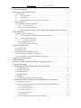
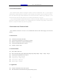
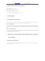
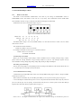
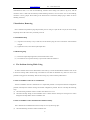
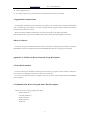
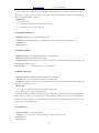
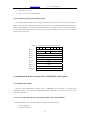
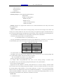
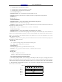
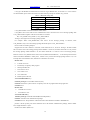
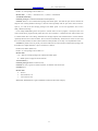
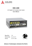
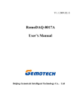
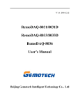
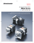
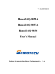
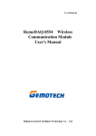
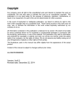
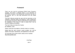
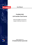
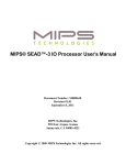
V1.1 2009.03.06
ISA-CAN20X2
User’s Manual
Beijing Gemotech Intelligent Technology Co.,Ltd
www.gemotech.cn
Tel:+8610 5885-1690
1 General Information .................................................................................................................................... 4
2 Performance and Technical Index ........................................................................................................ 4
2.1 Performance ........................................................................................................................4
2.2
Technical Index .........................................................................................................4
2.3
Application................................................................................................................4
2.4
Physical Dimension and Operation Environment .....................................................5
3
Work Principle .......................................................................................................................................... 5
3.1 Work Principle General Description ...................................................................................5
3.2.1
ISA-bus port part...............................................................................................5
3.2.2 CAN Communication Part .......................................................................................5
4
Main Element Location Figure, Signal Input/Output Socket and Switch
Choice Definition ............................................................................................................................................. 5
4.1 Main Element Location Figure ...........................................................................................5
4.2
ISA-CAN20X2 Signal Input/Output Socket Definition............................................6
4.3
Switch and Jumper Choice........................................................................................7
4.3.1
BASE of card choice.........................................................................................7
4.3.2 Interrupt Level Choice .............................................................................................7
4.3.3 Communication Port Setting ....................................................................................7
5 Installation, Removing ............................................................................................................................... 8
5.1 Installation Step...................................................................................................................8
5.2 Removing Step....................................................................................................................8
6
The Problem Solving While Using ................................................................................................. 8
6.1 ISA-CAN20X2 Card Can’t Communicate..........................................................................8
6.2 ISA-CAN20X2 Card Communication Fails Too Many ......................................................8
7 Application Attention Item....................................................................................................................... 9
8 Driver Software ............................................................................................................................................. 9
Appendix: CAN20 Card Driver Function Usage Description .................................................... 9
1 General Information .................................................................................................................................... 9
2 Communication Driver Program under Dos Description.......................................................... 9
2.1 InstallCANDriver( ) ..........................................................................................................10
2.2 UninstallCANDriver( ) .....................................................................................................11
2.3 SendCANFrame( ) ............................................................................................................11
2.4 ReadCANFrame( ) ............................................................................................................11
2.5 ClearError( )......................................................................................................................11
2.6 CAN Message Package Format Description .....................................................................12
3 Communication Driver Program under WINDOWS3.x Description................................ 12
3.1 Installation Description .....................................................................................................12
3.2 CAN Communication Driver Program Description under WINDOWS3.x ......................12
3.2.1 InstallCANDriver( ) ...............................................................................................13
3.2.2 UninstallCANDriver( )...........................................................................................14
3.2.3 SendCANFrame( ) .................................................................................................14
3.2.4 ReadCANFrame( ) .................................................................................................14
3.2.5 ClearError( ) ...........................................................................................................14
3.2.6 CAN Message Package Format Description ..........................................................14
2
www.gemotech.cn
4
Tel:+8610 5885-1690
Communication Driver Program under WINDOWS95/98 Description ..................... 15
4.1 Installation Description .....................................................................................................15
4.2 CAN Communication Driver Program Description under WINDOWS95/98 ..................15
4.2.1 InstallCANDriver( ) ...............................................................................................15
4.2.2 UninstallCANDriver( )...........................................................................................16
4.2.3 SendCANFrame() ..................................................................................................16
4.2.4 ReadCANFrame( ) .................................................................................................17
4.2.5 ClearError( ) ...........................................................................................................17
3
www.gemotech.cn
Tel:+8610 5885-1690
1 General Information
ISA-CAN20X2 double channel no-intelligent isolation CAN-bus communication card is a special purpose
communication card that offers the connectivity of the Controller Area Network (CAN) to ISA-bus of your PC.
This card satisfies the high real-time demand of CAN network, and with its built-in CAN controllers,it can
monitor and control the meter and control devices in industry field which have CAN ports.
CAN is a kind of all-digital communication network. At abroad, it has already installed lots of sensors, actuators
and motors etc industry devices that have CAN communication ports. At domestic, many industry control devices
that have CAN ports are admissive by most users gradually.
2 Performance and Technical Index
ISA-CAN20X2, with DC/AC in card, its CAN communication doesn’t need outside supply, fit for universal
situation.
2.1 Performance
z
2 channels 8 bits ISA-bus data width
z
CAN network communication can speed up to 1M bit/s
z
DOS driver, WIN9X driver, WIN NT/WIN2000 driver
z
CAN network adopt DB-9 male connector
z
1000VDC isolated voltage
2.2 Technical Index
z
ISA-bus data width: 8 bits
z
ISA-bus interrupt setting range: IRQ3, IRQ4, IRQ5, IRQ7, IRQ9, IRQ10,IRQ11,IRQ12,IRQ15
z
CAN network communication rate: 1M bit/s
z
CAN controller:Philips SJA1000
z
CAN transceiver:Philips 82c250
z
CAN connector:DB-9 male
z
Isolated voltage:1000VDC
2.3 Application
z
All kinds of distribution mode control system
z
The communication network desired strong anti-jamming capacity
4
www.gemotech.cn
Tel:+8610 5885-1690
2.4 Physical Dimension and Operation Environment
z
Dimension: 160mm ×107mm
z
Operating Temperature:0~50℃
z
Storage Temperature: -25℃~+85℃
Humidity:90% non-condensing
z
3
Power consumption:+5V@200mA (Typical value)
Work Principle
3.1 Work Principle General Description
ISA-CAN20X2 double channels no-intelligent isolation CAN-bus communication card can divide into two
parts according their function: ISA-bus port part and CAN network communication part.
3.2.1 ISA-bus port part
ISA-bus port part is the bridge of the data conversion between ISA-CAN20X2 card and PC’s CPU. The data
conversion between ISA-CAN20X2 card and PC’s CPU performs by ISA-bus circuit. The data width of ISA-bus is
8 bits.
3.2.2 CAN Communication Part
This part implement CAN physical layer and data link layer protocol. The function of this port has controlled by
the control circuit of the ISA-CAN20X2 card.
4
Main Element Location Figure, Signal Input/Output Socket and Switch
Choice Definition
4.1 Main Element Location Figure
Figure 4.1 is main element location figure of ISA-CAN20X2 double channels no-intelligent isolation CAN-bus
communication card.
5
www.gemotech.cn
Tel:+8610 5885-1690
Fig.4.1 ISA-CAN20X2 card main element location figure
Communication port 1:
CN1: CAN1 communication port
JP1: CAN1 Interrupt level choice jumper
JP2: The matching resistance of CAN1 choice jumper
BASEADDR1: CAN1 BASE of card choice switch
Communication port 2:
CN2: CAN2 communication port
JP3: CAN2 Interrupt level choice jumper
JP4: The matching resistance of CAN2 choice jumper
BASEADDR2: CAN2 BASE of card choice switch
4.2 ISA-CAN20X2 Signal Input/Output Socket Definition
Fig.4.2 ISA-CAN20X2 card signal input/output socket definition
Signal Description:
Bus-H: CAN communication signal high level
Bus-L: CAN communication signal low level
GND: Ground
6
www.gemotech.cn
Tel:+8610 5885-1690
4.3 Switch and Jumper Choice
4.3.1
BASE of card choice
The BASE of ISA-CAN20X2 communication card chose by the setting of BASEADDR1 switch or
BASEADDR2 switch. The BASE of card can set as any binary code combination between 200H~3F8H.
ISA-CAN20X2 card will occupy 8 continuous I/O addresses that begin from the BASE.
The BASE of card choice switch sketch map as fig.4.3.1:
Fig.4.3.1 ISA-CAN20X2 base address choice
Address line: A8
Decimal: 256
Hex:100
A7
A6 A5 A4
A3
128
64
32
16
08
80
40
20
10
08
The BASE address range is 512~1023 (0200H~03F8H). It is valid when switch is at “OFF”, and it is invalid
when switch is at “ON”.
The calculation formula of BASE is:
BASE=512 (200H) + sum of all valid bits.
For example: The BASE of card in fig.4.3.1 calculates as follows:
BASE of card= 512+ 128=640
Or=0200H+ 80H=0280H
4.3.2 Interrupt Level Choice
Before you set the interrupt request jumper of ISA-CAN20X2 card, for avoiding interrupt occupy conflict,
please check the existing hardware occupy interrupt situation of your PC. The interrupt requests used by
ISA-CAN20X2 are IRQ3, IRQ4, IRQ5, IRQ7, IRQ9, IRQ10, IRQ11, IRQ12 and IRQ15.
The setting way of interrupt:
The user can set the jumper in corresponding location according to the definition of JP1 and JP3. When JP1 is at
“×”, it means there isn’t interrupt level has been chosen.
4.3.3 Communication Port Setting
Communication port adopt DB-9 male socket, user can adopt DB-9 female plug to connect it. The pins of DB-9
socket refer to section 4.2.
When used ISA-CAN20X2, only uses the BUS_H and BUS_L of CN1 port. The wiring way sees fig.4.2.3.
CAN is half-duplex communication protocol. So user can perform the data transmit and receipt only need one
pair wire, but this pair wire has polarity. If network has many devices to connect, please connect their BUS_H
together and connect their BUS_L together (Refer to fig.4.3.3).
Since CAN is a all-digital communication, the signal exist reflection during its transmission process in
7
www.gemotech.cn
Tel:+8610 5885-1690
communication cable; so it need to add matching resistance when setting CAN (Refer to fig.4.3.3), and the
resistance value is 120Ω. This card already installs matching resistance, user can choose if to use the matching
resistance or not by jumper JP2 according to the factual need of work field (Jumper plug in means to choose
matching resistance).
5 Installation, Removing
ISA-CAN20X2 card prohibit to plug and pull when power on. Plug in or pull out the wire pin, the switch setting
and jumper choice all need to carry out under power off.
5.1 Installation Step
(1) Align the card vertically to any extend slot, and use hand to plug the card to extend slot with downward
strength.
(2) Tighten the screws, and connect input/output cable.
5.2 Removing Step
(1) Disconnect input/output signal cable, and tweak down the screws.
(2) Two hand use force upward vertically, to pull out the card from extend slot.
6
The Problem Solving While Using
All ISA-CAN20X2 cards will be checked before leave factory, to ensure the manufacture handed to user accord
to the need of design index. But the using environment of user differ in thousands ways, there will occur some
problem at using process unavoidably. There are the solving ways of the common problem below.
6.1 ISA-CAN20X2 Card Can’t Communicate
The ISA-CAN20X2 card can’t communicate is a complicated problem. It is maybe the hardware configuration
problem, and maybe the software running environment configuration problem. The user can adopt the following
steps:
(1) Check the setting of address switch if conflict with other device or not.
(2) Check the interrupt setting of ISA-CAN20X2 card if conflict with the interrupt of existing device. Please
change the interrupt number of ISA-CAN20X2 card.
6.2 ISA-CAN20X2 Card Communication Fails Too Many
ISA-CAN20X2 card communication fails too many can solve by following steps:
(1) Check the matching resistance of ISA-CAN20X2 card.
8
www.gemotech.cn
Tel:+8610 5885-1690
(2) Choose appropriate wire.
(3) According to the protocol of CAN network, check if the network structure is reasonable.
7 Application Attention Item
At the package of manufacture that works off by the company, user will find a ISA-CAN20X2 communication
card, a 3.5inch floppy disk (Include a set of driver program and test program of ISA-CAN20X2 card and this
instruction book’s electronic version).
Before uses ISA-CAN20X2 communication card, please pay attention to the following problem:
Don’t touch the front IC chip of ISA-CAN20X2 card by hand, avoiding the chip damaged by electrostatic.
8 Driver Software
For the user using ISA-CAN20X2 card flexibly and conveniently, we make program of DOS driver program,
WINDOWS 16 bits driver program (Fit for Win95) and WINDOWS 32 bits driver program (Fit for Win98).
Appendix: CAN20 Card Driver Function Usage Description
1 General Information
For the user using ISA-CAN20X2 card flexibly and conveniently, we program CAN20 card driver function for
user. User can use C language to call the driver function of CAN20 card.
In user driver program disk, there are examples of how to call driver function under DOS and WINDOWS,
please refer them.
2 Communication Driver Program under Dos Description
There are 5 function of driver program under DOS:
·InstallCANDriver( )
·UninstallCANDriver( )
·SendCANFrame( )
·ReadCANFrame( )
·ClearError( )
9
www.gemotech.cn
Tel:+8610 5885-1690
2.1 InstallCANDriver( )
Function prototype: int InstallCANDriver(
unsigned int CAN_BaseAddress,
unsigned char CAN_IntNo,
unsigned int
CAN_bps,
unsigned char CAN_StationAddress,
unsigned char CAN_Mask,
void(_far*Callback)(int Index)
);
Function: Initialize all registers of CAN20 communication card, set interrupt vector and recall function, read
for normal communication.
Parameter: CAN_BaseAddress is the BASE of card, corresponding to the dial switch of card address.
CAN_IntNo is the interrupt number of communication card.
Its calculation formula is: CAN_IntNo=IRQ No. -8+112
CAN_bps is the baudrate of communication card. It has 5 types baudrate now, see to table 2.1. If user wants
to use other baudrate, please refer to the book concerned CAN-bus principle to calculate it by yourself.
Table 2.1 Baudrate Setting Table
Baudrate
CAN _bps
1M
0xC0A3
500K
0xC1A3
250K
0xC3A3
125K
0xC7A3
50K
0xC7AF
CAN_StationAddress is the station address of this station.
CAN_Mask is the receive mask word of communication card, as the decision to receive message package with
CAN_ StationAddress together. The decision formula is as follows:
ID︱CAN_MASK=CAN_MASK︱CAN_ StationAddress
Among it, ID is high 8 bits of message package symbol.
For example: When CAN_MASK=0xFF, then receive all the message package of network; when
CAN_MASK=0, only receive the message package which ID equal to CAN_ StationAddress.
Receive mask word setting example:
Suppose there are total 3 stations in CAN-bus, set the station ID as: 10, 12 and 13. Among it: the station which
ID is 10 need to receive the message package which identifier is 10 and 11; the station which ID is 12 only concern
the message package which identifier is 12; the station which ID is 13 want to receive all message package.
Because 10 and 11 only different in the most lowest bit (00001010 and 00001011),so the interrupt mask word of
station 10 should be 00000001,namely 0x01;Station 12 only concerns the message package relative to it, so its
interrupt mask word should be 0x00, and station 13 should be set as 0xFF.
Callback is the pointer to the recall function that programmed by user, the prototype of recall function is:
void(_far*CallbachFunctionName)(int Index);
Among it:
Index=1:When receive buffer area is empty and there are new message package coming, interrupt service
program uses this value call recall function. User should call ReadCANFrame( ) function to receive message
package. (Please refer to the description of ReadCANFrame( ) function.)
10
www.gemotech.cn
Tel:+8610 5885-1690
Index=2: When receive buffer area is full, interrupt service program uses this value call recall function. User can
deal with it by oneself. This pointer also can be empty, and user read message packages from buffer area by
directly call ReadCANFrame( ) function.
Return value:
0---- Install success.
1---- Install fail, and the called parameters of port isn’t right.
2---- Install fail, as to write CAN register fail.
2.2 UninstallCANDriver( )
Function prototype: void UninstallCANDriver(void);
Function: Release the system resource occupied by CAN driver program before the program exit.
Parameters: no.
Return value: no.
2.3 SendCANFrame( )
Function prototype: int SendCANFrame(unsigned char_far·pHrame);
Function: Transmit CAN communication package.
Parameters: pFrame is the far pointer point to the buffer that saves the transmit communication package, and
this buffer area’s length is 10 bytes.
Return value:
1
----Transmit success;0 ----Transmit fail.
2.4 ReadCANFrame( )
Function prototype: int RendCANFrame(unsigned char_far*pHrame);
Function: Receive CAN communication package from buffer queue.
Parameters: pFrame is the far pointer point to the buffer that saves the transmit communication package, and
this buffer area’s length is 10 bytes.
Return value:
>0---- There are message packages not read from the buffer queue.
≤0---- Buffer queue is empty and can be returned.
Note: When this port call the recall function at disposal code Index=1, must call repeatedly until the port return
value less than or equal 0, viz. read out all the message packages from buffer queue. Or else interrupt service
program won’t call recall function, until the buffer area is full and call recall function again with Index=2. This
port also can be called independently.
2.5 ClearError( )
Function prototype:
int ClearError(void);
Function: Set every register of CAN20 card anew, to eliminate some casual error.
Parameters: no.
Return value:
11
www.gemotech.cn
Tel:+8610 5885-1690
1---- Eliminate error success.
0---- Have severe error, can’t eliminate error.
2.6 CAN Message Package Format Description
CAN message package include 2 parts: message part and data part. The first 2 bytes is message part, and the
former 11 bits is identifier. The former 8 bits uses to receive decision, which should include the destination address
of this message package, the following bit is RTR bit (should set as 0), and the last 4 bits is DLC (Data Length Bit,
viz. the actual length of transmit data, unit: byte.). The rest 8 bytes are data part, which save the actual transmit
data. See table 2.6 for detail.
Table 2.6 CAN message package format description
7
Byte 1
Byte 2
6
5
4
3
2
1
0
Identifier (High 8 bits)
Identifier
RTR
Byte 3
Data
Byte 4
Data
Byte 5
Data
Byte 6
Data
Byte 7
Data
Byte 8
Data
Byte 9
Data
Byte 10
Data
DLC
3 Communication Driver Program under WINDOWS3.x Description
3.1 Installation Description
The driver under WINDOWS3.x includes 2 files: CANDRV.DLL and FUNCS.DLL. Copy them from
WINDOWS directory of floppy disk to WINDOWS\SYSTEM of hard disk or the directory where the user
application program lie in.
3.2 CAN Communication Driver Program Description under WINDOWS3.x
Under WINDOWS3.x CAN communication driver program includes 5 functions:
·InstallCANDriver( )
·UninstallCANDriver( )
12
www.gemotech.cn
Tel:+8610 5885-1690
·SendCANFrame( )
·ReadCANFrame( )
·ClearError( )
3.2.1 InstallCANDriver( )
Function prototype: int_export WINAPI InstallCANDriver(
HWND hWnd,
WORD CAN_BaseAddress,
WORD CAN_IntNo,
WORD CAN_bps,
WORD CAN_StationAddress,
WORD CAN_Mask);
Function: Initialize every registers and virtual devices of CAN20 communication card, ready for the normal
CAN communication.
Parameters:
HWnd is window handle. After connect to message package, virtual will send a message to this window. The
message value is WM_USER+255. After receive this message, user application program call ReadCANFrame( )
port to read all message package from buffer queue, until the queue is empty. And perform corresponding disposal.
CAN_BaseAddress is the BASE of card, corresponding to the dial switch of card address.
CAN_IntNo is the interrupt number of communication card.
Its calculation formula is: CAN_IntNo=IRQ No. -8+112
CAN_bps is the baudrate of communication card. It has 5 types baudrate now, see to table 3.2.1. If user wants to
use other baudrate, please refer to the book concerned CAN-bus principle to calculate it by yourself.
Table 3.2.1Baudrate setting table
Baudrate
CAN _bps
1M
0xC0A3
500K
0xC1A3
250K
0xC3A3
125K
0xC7A3
50K
0xC7AF
CAN_StationAddress is the station address of this station.
CAN_Mask is the receive mask word of communication card, as the decision to receive message package with
CAN_ StationAddress together. The decision formula is as follows:
ID︱CAN_MASK=CAN_MASK︱CAN_ StationAddress
Among it, ID is high 8 bits of message package symbol.
For example: When CAN_MASK=0xFF, then receive all the message package of network; when
CAN_MASK=0, only receive the message package which ID equal to CAN_ StationAddress.
Receive mask word setting example:
Suppose there are total 3 stations in CAN-bus, set the station ID as: 10, 12 and 13. Among it: the station which
ID is 10 need to receive the message package which identifier is 10 and 11; the station which ID is 12 only concern
the message package which identifier is 12; the station which ID is 13 want to receive all message package.
Because 10 and 11 only different in the most lowest bit (00001010 and 00001011),so the interrupt mask word of
station 10 should be 00000001,namely 0x01;Station 12 only concerns the message package relative to it, so its
interrupt mask word should be 0x00, and station 13 should be set as 0xFF.
Return value:
0---- Installation success
13
www.gemotech.cn
Tel:+8610 5885-1690
1---- Installation fail, and virtual device not load.
2---- Installation fail, and call port parameters isn’t right.
3---- Installation fail, and virtual device initialize fail.
3.2.2 UninstallCANDriver( )
Function prototype: void_export WINAPI UninstallCANDriver(void);
Function: Release the system resource occupied by CAN driver program before the program exit.
Parameters: no.
Return value: no.
3.2.3 SendCANFrame( )
Function prototype: int_export WINAPI SendCANFrame(BYTE FAR*pFrame);
Function: Transmit CAN communication package.
Parameters: pFrame is the far pointer point to the buffer that saves the transmit communication package, and
this buffer area’s length is 10 bytes.
Return value:
1 (True) ----Transmit success;0 (False)----Transmit fail.
3.2.4 ReadCANFrame( )
Function prototype: int_export WINAPI ReadCANFrame(BYTE FAR *pFrame);
Function: Receive CAN communication package from buffer queue. Note that this port must be called at the
disposal code of WM_USER+255 message. It must be called repeatedly until the port return value less than or
equal 0, viz. read out all the message packages from buffer queue. Or else user application can’t receive
WM_U-SER+255 message.
Parameters: pFrame is the far pointer point to the buffer that saves the transmit communication package, and
this buffer area’s length is 10 bytes.
Return value:
>0---- There are message packages not read from the buffer queue.
≤0---- Buffer queue is empty and can be returned.
3.2.5 ClearError( )
Function prototype: BOOL_export WINAPI ClearError(void);
Function: Set every register of CAN20 card anew, to eliminate some casual error.
Parameters: no.
Return value:
1 (True)---- Eliminate error success.
0 (False)---- Have severe error, can’t eliminate error.
3.2.6 CAN Message Package Format Description
CAN message package include 2 parts: message part and data part. The first 2 bytes is message part, and the
former 11 bits is identifier. The former 8 bits uses to receive decision, which should include the destination address
of this message package, the following bit is RTR bit (should set as 0), and the last 4 bits is DLC (Data Length Bit,
viz. the actual length of transmit data, unit: byte.). The rest 8 bytes are data part, which save the actual transmit
data. See table 3.2.6 for detail.
Table 3.2.6 CAN message package format description
7
Byte 1
Byte 2
6
5
4
3
2
1
Identifier (High 8 bits)
Identifier
RTR
Byte 3
Data
Byte 4
Data
Byte 5
Data
14
DLC
0
www.gemotech.cn
Tel:+8610 5885-1690
Byte 6
Data
Byte 7
Data
Byte 8
Data
Byte 9
Data
Byte 10
Data
4 Communication Driver Program under WINDOWS95/98 Description
4.1 Installation Description
The driver under WINDOWS95/98 includes 2 files: CANDRV.DLL and HK_CAN.VXD. Copy them from
WIN95 directory of floppy disk to WINDOWS\SYSTEM of hard disk or the directory where the user application
program lie in.
4.2 CAN Communication Driver Program Description under WINDOWS95/98
Under WINDOWS95/98 CAN communication driver program includes 5 functions:
·InstallCANDriver( )
·UninstallCANDriver( )
·SendCANFrame( )
·ReadCANFrame( )
·ClearError( )
The calling ways of each function is similar with that under WINDOWS3.x, and add some error message, to
help user to analyze. Please refer to the following description.
4.2.1 InstallCANDriver( )
Function prototype: int InstallCANDriver(
HWND hWnd,
WORD CAN_BaseAddress,
WORD CAN_IntNo,
WORD CAN_bps,
WORD CAN_StationAddress,
WORD CAN_Mask);
Function: Initialize every registers and virtual devices of CAN20 communication card, ready for the normal
CAN communication.
Parameters:
HWnd is window handle. After connect to message package, virtual will send a message to this window. The
message value is WM_USER+255. After receive this message, user application program call ReadCANFrame( )
port to read all message package from buffer queue, until the queue is empty. And perform corresponding disposal.
If hWnd is 0, user need receive notice from multithreading and event system to read message package.
CAN_BaseAddress is the BASE of card, corresponding to the dial switch of card address.
CAN_IntNo is the interrupt number of communication card.
Its calculation formula is: CAN_IntNo=IRQ No. -8+112
15
www.gemotech.cn
Tel:+8610 5885-1690
CAN_bps is the baudrate of communication card. It has 5 types baudrate now, see to table 3.2.1. If user wants to
use other baudrate, please refer to the book concerned CAN-bus principle to calculate it by yourself.
Table 3.2.1Baudrate setting table
Baudrate
CAN _bps
1M
0xC0A3
500K
0xC1A3
250K
0xC3A3
125K
0xC7A3
50K
0xC7AF
CAN_StationAddress is the station address of this station.
CAN_Mask is the receive mask word of communication card, as the decision to receive message package with
CAN_ StationAddress together. The decision formula is as follows:
ID︱CAN_MASK=CAN_MASK︱CAN_ StationAddress
Among it, ID is high 8 bits of message package symbol.
For example: When CAN_MASK=0xFF, then receive all the message package of network; when
CAN_MASK=0, only receive the message package which ID equal to CAN_ StationAddress.
Receive mask word setting example:
Suppose there are total 3 stations in CAN-bus, set the station ID as: 10, 12 and 13. Among it: the station which
ID is 10 need to receive the message package which identifier is 10 and 11; the station which ID is 12 only concern
the message package which identifier is 12; the station which ID is 13 want to receive all message package.
Because 10 and 11 only different in the most lowest bit (00001010 and 00001011),so the interrupt mask word of
station 10 should be 00000001,namely 0x01;Station 12 only concerns the message package relative to it, so its
interrupt mask word should be 0x00, and station 13 should be set as 0xFF.
Return value:
0
Load driver success.
2
Port already occupied by other program.
3
Interrupt initialize fail.
7
CAN card isn’t exist.
9
Can’t create event.
11
Can’t load VXD.
14
Bottom queue create fail.
4.2.2 UninstallCANDriver( )
Function prototype: int UninstallCANDriver(void);
Function: Release the system resource occupied by CAN driver program before the program exit.
Parameters: no.
Return value:
0
Uninstall driver success.
5
Not load driver ever.
4.2.3 SendCANFrame()
Function prototype: int SendCANFrame(BYTE FAR*pFrame);
Function: Transmit CAN communication package.
Parameters: Note: The parameters of this function have more different with that in WINDOWS3.1.
pFrame is the far pointer point to the buffer that saves the transmit communication package, and this buffer
area’s length should be 11 bytes.
BYTE0: Port number (Must be 0).
16
www.gemotech.cn
Tel:+8610 5885-1690
BYTE1~10: CAN package, refer to table 3.2.6.
Return value: 1 (True) ----Transmit success;0 (False)----Transmit fail.
4.2.4 ReadCANFrame( )
Function prototype: int ReadCANFrame(BYTE FAR*pFrame);
Function: Receive CAN communication package from buffer queue. Note that this port must be called at the
disposal code of WM_USER+255 message. It must be called repeatedly until the port return value less than or
equal 0, viz. read out all the message packages from buffer queue. Or else user application can’t receive
WM_U-SER+255 message.
If user adopt multithreading and event system to wait the notice of driver program, it need open (Note: Not
create, because driver program already create this event.) an event named “CanReceiveEvent”and wait this event
at a thread. When this event coming, should like the message disposal code mentioned above, call this function
repeatedly until the return value less than 0. This event restore automatically, needn’t the user restore it. Don’t wait
this event in many threads, also don’t call this function in many threads, or else may occur unpredictable results.
Parameters: pFrame is the far pointer point to the buffer that saves the transmit communication package, and
this buffer area’s length should be 11 bytes. Its format is as follows:
BYTE0: Port number (Must be 0).
BYTE1~10: CAN package, refer to table 3.2.6.
Return value:
≥0---- There are message packages not read from the buffer queue.
<0---- Buffer queue is empty and can be returned.
4.2.5 ClearError( )
Function prototype: BOOL ClearError(void);
Function: Set every register of CAN20 card anew, to eliminate some casual error.
Parameters: no.
Return value:
0
Success.
5
Not load driver ever.
7
CAN card isn’t exist.
Note: DOS, WINDOWS are register trademarks of American Microsoft Company.
17