1
MH Pro! User Manual
Screen Descriptions and Selected Special Topics
Software For Manhole Producers
FBE Associates, Inc.
513 N, Madison Ave
Suite 101
Bay City, MI 48708
866-894-2785
989-894-2805 fax
www.fbe-inc.com
MH Po! User Guide
©2007 - 2008 FBE Associates, Inc.
All rights reserved. No parts of this work may be reproduced in any form or by any means - graphic, electronic, or
mechanical, including photocopying, recording, taping, or information storage and retrieval systems - without the
written permission of FBE Associates, Inc.
Current MH Pro! License holders are allowed to make any copies of MH Pro! documents that further their direct
manhole related business activities. Others may request authorization for copies of selected material from FBE
Associates, Inc. by calling 1-866-894-2785.
MH Pro! is a trademark of FBE Associates, Inc.
Products that are referred to in this document may be either trademarks and/or registered trademarks of the
respective owners. FBE Associates, Inc. Make no claim to these trademarks.
While every precaution has been taken in the preparation of this document, FBE Associates, Inc. assumes no
responsibility for errors or omissions, or for damages resulting from the use of information contained in this document
or from the use of programs and source code that may accompany it. In no event shall FBE Associates, Inc be liable
for any loss of profit or any other commercial damage caused or alleged to have been caused directly or indirectly by
this document.
Printed: February 2008
Contents
3
Table of Contents
Foreword
Part I Overview
5
6
1 Users' Guide ...................................................................................................................................
Descriptions
8
Part II Screen Descriptions
9
1 Automatic Stacking
...................................................................................................................................
Screen
10
2 Butterfly View
...................................................................................................................................
Screen
12
3 Elevation View
...................................................................................................................................
Screen
13
4 Fabricated Steel
...................................................................................................................................
Screen
14
5 Flow Tree Screen
................................................................................................................................... 17
6 Job Data Screen
................................................................................................................................... 19
7 Job Screen ................................................................................................................................... 21
8 Link Data Screen
................................................................................................................................... 22
9 Main Screen................................................................................................................................... 24
10 Migration Screen
................................................................................................................................... 26
11 Miscellaneous
...................................................................................................................................
Items Screen
29
12 Notes Screen
................................................................................................................................... 32
13 Pipe Fittings...................................................................................................................................
Screen
33
14 Pipe Screen................................................................................................................................... 40
15 Plan View Screen
................................................................................................................................... 49
16 Platforms Screen
................................................................................................................................... 51
17 Pricing Screen
................................................................................................................................... 52
18 Reports Screen
................................................................................................................................... 55
19 Rollout View...................................................................................................................................
Screen
56
20 Site Plan Screen
................................................................................................................................... 57
21 Stack Editor...................................................................................................................................
Screen
58
22 Status Screen
................................................................................................................................... 60
23 Structure Design
...................................................................................................................................
Screen
61
24 Structure Screen
................................................................................................................................... 70
Part III Special Topics
73
1 Bill of Materials
................................................................................................................................... 74
2 Drop Manholes
................................................................................................................................... 75
3 Flow Tree vs.
...................................................................................................................................
Drainage System
77
4 Measuring in...................................................................................................................................
Graphic Views
78
5 Non-Standard
...................................................................................................................................
Structures (Mostly Vaults)
79
© 2008 FBE Associates, Inc.
3
4
MH Pro! User Guide
6 Offset Holes................................................................................................................................... 81
7 Reference Jobs
...................................................................................................................................
and Structures
85
8 Shallow Structures
................................................................................................................................... 87
9 Sorting Uses................................................................................................................................... 88
10 Take-Off Measurements
................................................................................................................................... 89
11 Units of Measure
................................................................................................................................... 90
90
Part IV Customization
1 Populate Database
...................................................................................................................................
Tables
92
2 Customization
...................................................................................................................................
of Special Rules
93
3 Setup Outputs
................................................................................................................................... 94
4 Installation ................................................................................................................................... 95
96
Part V Workflow
1 Setup the Job
................................................................................................................................... 97
2 Create the Flow
...................................................................................................................................
Tree
99
3 Enter the Structure
...................................................................................................................................
Data
101
4 Validate the...................................................................................................................................
Structure Data
102
5 Stack the Structures
................................................................................................................................... 104
6 Create the ...................................................................................................................................
Outputs
105
Part VI Example
108
1 Reviewing ...................................................................................................................................
the Engineering Drawings
109
2 Setting Up ...................................................................................................................................
the Job
112
3 Creating and
...................................................................................................................................
Naming the Structures
114
4 Defining the
...................................................................................................................................
Structures
117
5 Stacking the
...................................................................................................................................
Structures
122
6 Viewing the...................................................................................................................................
Takeoff Graphics
124
7 Producing ...................................................................................................................................
the Output Documents
127
Part VII Add-Ons
130
1 Simple Quote
...................................................................................................................................
Instructions
130
Quoting (Per..........................................................................................................................................................
Piece)
Quoting (Per..........................................................................................................................................................
Structure)
Quoting (By ..........................................................................................................................................................
Depth)
Quoting (Mixed)
..........................................................................................................................................................
Index
132
134
136
139
142
© 2008 FBE Associates, Inc.
Foreword
5
Forward
MH Pro! is a software application that is constantly being upgraded as users suggest refinements, as
existing companies request additional functionality and as new precast companies present their
requirements to FBE engineers. Getting new "builds" of MH Pro! out to those who need them, and training
our new customers, keeps our staff very busy. We have tried to determine the best way to augment the
on-line help files and are now providing this paper MH Pro! User Manual.
This MH Pro! User Manual captures the state of MH Pro! as of the date on the copyright page (Page 2).
We do not think that updating all the documentation on paper for each build makes sense for us or for our
customers. We have decided to send one Comprehensive User Manual to each site that contains all the
information in the on-line User Guide, and a smaller version with only Screen Descriptions and Special
Topics for each MH Pro! user at that customer site.
As new versions of MH Pro! are provided individual customers, and the screens change in a meaningful
way, we will send by e-mail files containing the revised Screen Descriptions and Special Topics. Updated
Comprehensive MH Pro! User Manuals will be produced as needed. The result of using this method of
providing paper User Manuals is that it is possible that the screens displayed in the Workflow, Example and
Special Topics sections may not be exactly the same ast the screens that appear in the most current screen
descriptions. In most cases this should not cause a problem in understanding hot to complete a set of
actions within MH Pro! because the new Screen Desciptions should explain hot to use the new screens
adequately. If there is a major conflict then we will also change the out of date on-line sections and send
e-mail versions of the new material to each customer contact. And remember that calling 1-866-894-2785 is
the fastest way to get help with your MH Pro! usage questions.
We hope that this MH Pro! User Manual helps make your experience with MH Pro! even more productive,
and as always, we would like your input on how to improve it, and the screens and functions of MH Pro!
Pat Race
President
Tom Goodman
Senior Consultant
© 2008 FBE Associates, Inc.
6
1
MH Pro! User Guide
Overview
FBE Associates, Inc
513 N Madison Ave, Suite 101
Bay City, MI 48708-6460, USA
www.fbe-inc.com Vistit us on the web!
© 2008 FBE Associates, Inc. All Rights Reserved.
MH Pro! TM is a trademark of FBE Associates, Inc.
989.894.2805 Phone
989.894.2805 Fax
866.894.2785 Toll Free
This Overview has six parts that make up a basic description of the resources available and
the steps that must happen within an organization to implement and make full use of MH Pro!
1. Screen Descriptions:
This section explains the various screens that make up MH Pro! software.
2. Special Topics:
Special Topics cover a range of issues that relate to MH Pro! but do not fall into one of the
main sections of the help documentation. The topics range from MH Pro! specific concerns to
manhole nomenclature to application usage ideas.
3. Customization: This setion will explain how the software is customized for your company
and the database is generated.
4. Workflow:
What follows is a discussion of how MH Pro! can be used to assist with takeoff and structure
drawing creation for the structures in a drainage system.
5. Example:
This section leads the user through a short example of a takeoff job using MH Pro! to capture
takeoff information, stack selected drainage structures, and produce all the associated output
documentation.
© 2008 FBE Associates, Inc.
Overview
7
6. Add-Ons:
This section contains information on the various Add-On Modules that extend the capabilities
of MHPro!.
Please also see the Users' Guide Descriptions which describes the workflow for MH Pro! as
well as a number of setup and initialization activities that must take place before the
application can be used. This section also contains links to all manual topics as well as all sub
topics.
© 2008 FBE Associates, Inc.
8
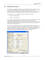
1.1
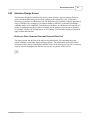
MH Pro! User Guide
Users' Guide Descriptions
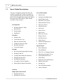
The Users’ Guide Descriptions describes the
workflow for MH Pro! as well as a number of
setup and initialization activities that must take
place before the application can be used. Most of
the setup work will be done by FBE with the
assistance of the customer.
Customization
·
·
·
·
Populate Database Tables
Special Rules
Setup Outputs
Installation
Workflow
·
·
·
·
·
·
Setup the Job
Create the Flow Tree
Enter the Structure Data
Validate the Structure Data
Stack the Structures
Create the Outputs
Example
·
·
·
·
·
·
·
Reviewing the Engineering Drawings
Setting Up the Job
Creating and Naming the Structures
Defining the Structures
Stacking the Structures
Viewing the Takeoff Graphics
Producing the Outputs Documents
Screen Descriptions
·
·
·
·
·
·
·
·
·
·
·
·
·
·
·
·
Main Screen
Automatic Stacking Screen
Stack Editor Screen
Elevation View Screen
Fabricated Steel Screen
Flow Tree Screen
Job Data Screen
Job Screen
Notes Screen
Pipe Screen
Plan View Screen
Reports Screen
Site Plan Screen
Status Screen
Structure Design Screen
Structure Screen
Special Topics
·
·
·
·
·
·
·
·
·
·
·
Bill of Materials
Drop Manholes
Flow Tree vs. Drainage System
Measuring in Graphic Views
Non-Standard Structures
Offset Holes
Reference Jobs and Structures
Shallow Structures
Sorting Uses
Take-Off Measurements
Units of Measure
Add-Ons
Simple Quote Instructions
· Quoting (Per Piece)
· Quoting (Per Structure)
© 2008 FBE Associates, Inc.
Overview
·
·
2
9
Quoting (By Depth)
Quoting (Mixed)
Screen Descriptions
This section presents descriptions of the screens that make up MH Pro!. They are presented
below grouped by the general functions they most often perform. Each screen name can be
clicked on which will then take you to that screen full description.
Setup and Input for a Job
Job
Job Data
Pipe
Misc. Items
Navigation and Special Functions
Site Plan
Fabricated Steel
Pricing
Structure Design
Flow Tree
Migration
Link Data
Flow Tree
Fabricated Steel
Notes
Misc. Items
Structure Design
Platform
Elevation
Rollout
Butterfly
Status
Structure Data Input
Structure
Pipe
Graphic Views
Plan
Site Plan
Stacking and Report Generation
Reports
Stack Editor
Automatic
Stacking
Each screen will be presented in grouped order in this section. It is also worth repeating that
the screens in the Customization, Workflow and Example Sections of the Comprehensive
MH Pro! User’s Guide may not be exactly as they appear in this section. This section has the
most current version of each screen as it appears in MH Pro!
© 2008 FBE Associates, Inc.
10
2.1
MH Pro! User Guide
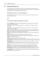
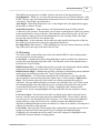
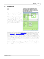
Automatic Stacking Screen
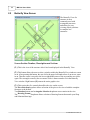
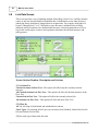
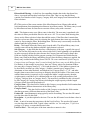
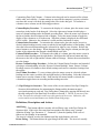
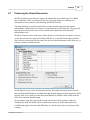
Much of the work done in MH Pro! is done with this screen. The structures, after all
definition data is entered and applied, are stacked here. The system is set up to automatically
determine the best possible stack based on information provided by the user on this screen,
the Structure screen and the Structure Design screen. The user then selects one stack from the
list of possible stacks to commit that stack to the current structure.
Screen Section Number, Description and Actions
(1.) Manufacturing Build Height - These are the manufacturing constraints that limit the
build height of the structure.
(2.) Design Build Height - These are the engineering requirements for this structure.
(3.) Stack Build Height - This section shows how the selected pieces satisfy the
manufacturing limits and engineering requirements.
(4.-A) Goodness Criteria - Goodness is a list of sorting criteria that cause candidate stacks
to be considered better or more desirable than others. These criteria are used to order the
display of the stacks found by Auto Stacking. The following are terms which give preferences
to a specific candidate stack based on how high in the Goodness Criteria list a preference term
is. The options can be moved up or down in the list to give more or less weight to that
particular item.
Absolute Variance - A preference for the variance height to approach zero after the structure
is stacked. That is, as much Build Height in precast as possible, less in build tolerance.
© 2008 FBE Associates, Inc.
Screen Descriptions
11
Collision Count - Counts the intersections where a hole intersects the boundary of a piece in
the structure. The preference is to keep these collisions to a minimum.
Full Size Count - For reducing structures preference would be given to the stack with the
fewest full size (larger) pieces.
Height Variance - A preference for stacks that have more precast and less empty adjustment.
This signed Goodness is used in “over-height” conditions and should be lower in priority than
Absolute Variance.
Outlet in Riser - A preference for a stack with the outlet hole in a riser.
Prefer Cone - Preference is given to using a cone at the top of the structure if it fits the top
criteria.
Prefer Slab Top - Preference is given to using a slab top.
Preferred Parts - Preference is given to certain parts. As an example, for bases which can be
18, 24 and 30 inches high, the stack with the 24” height base is preferred.
Riser Hole - Preference is given for a base with riser combination where the hole has its
bottom coincident with the bottom of the riser.
Section Count - Preference is to keep the number of Pieces to a minimum. The format is
(Pieces.Adjusting Rings).
Short Base - Preference is given to using the shortest height base.
Springline Base - Preference for placing the centerline of the pipe at the seam between
pieces, so that half of the pipe hole is in each piece.
Tall Base - Preference is given to using the tallest height base.
Taller Lower - Preference is given to stacks where the taller risers are lower in the structure.
(4.-B) The Find Stackings button simply starts the search routine. Progress is updated
constantly until the search ends. To end a search before it terminates naturally, press the Abort
Stacking button. The Abort Stacking button ends any search prior to its natural termination.
For instance, if the desired stacking has already been displayed in the Possible Stacks list, the
search may be aborted and that stacking selected and committed to the structure and the job.
(5.) Current Stacking - The stack for this particular structure that is saved in the job.
(6.) Stacking Results - A list of valid stacks for the current structure found by the search
algorithm. This list is sorted according to user specified Goodness criteria and displayed with
the "best" stack listed in the left-most position. To commit a potential stack as the Current
Stacking, press the button above the potential stack you want.
© 2008 FBE Associates, Inc.
12
2.2
MH Pro! User Guide
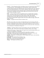
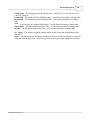
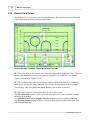
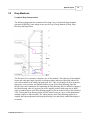
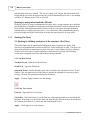
Butterfly View Screen
The Butterfly View of a
structure is most
commonly used with
rectangular structures
and allows for easy
viewing of hole positions
in complex box
structures.
Screen Section Number, Description and Actions
(1.) This is the view of the structure after it has been displayed in the Butterfly View.
(2.) This button allows the user to select a window within the ButterflyView window to zoom
in on. After pressing this button, the user clicks the upper-left-hand-corner of an area to zoom
in on. Then the cursor is moved to the lower-right-hand-corner of the area and the user clicks
again. The rectangle created by the two mouse clicks is then zoomed to fit in the Butterfly
View window. Right button (4.) returns the entire graphic view.
(3.) This section has five controls that affect the view on the screen:
The Piece Selection dropdown allows selection of the piece to be viewed with the complete
Structure as the default.
Two Rotation buttons and an Angular Selection dropdown cause rotation in the view.
The Drawing Format dropdown allows selection of drawing formats that match your Shop
and Submittal drawings.
© 2008 FBE Associates, Inc.
Screen Descriptions
2.3
13
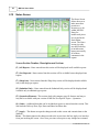
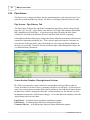
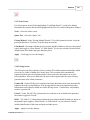
Elevation View Screen
The elevation view
shows the structure
from the side. This is
very helpful when
checking the stacking
accuracy of the
structure. If a field
elevation has been
entered incorrectly,
the error can be
easily noticed when
examining the
structure in this
view.
Screen Section Number, Description and Actions
(1.) This window displays the elevation view for a structure. It allows you to check for
errors that may have been made in defining a structure. Note that the system will accurately
display the entered opening locations, even if the location data entered is incorrect, and that
each precast element is labeled with letters.
(2.) This button allows the user to select a window within the Elevation View window to
zoom in on. See the Plan View or Site Plan screens for instructions on how to use the Zoom
feature.
(3.) This section has three controls that affect the view on the screen:
The Piece Selection dropdown allows selection of the piece to be viewed with the complete
Structure as the default.
Clicking on the Orientation dropdown allows you to rotate the view of the structure, Front
A-A is the default view.
The Drawing Format dropdown allows selection of drawing formats that match your Shop
and Submittal drawings.
(4.) The Zoom All button changes the scale of the Elevation View window so that the
entire structure is displayed in the window.
© 2008 FBE Associates, Inc.
14
2.4
MH Pro! User Guide
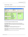
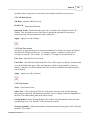
Fabricated Steel Screen
The Fabricated Steel & Cast Iron Screen allows the user to define all the casting types and
sizes that will be used in a particular job. Once the casting has been defined, it can be selected
from the Structure screen for placement in the structure.
Fabricated Steel Screen - Frames & Rings Tab
The fields on the top half of the screen are used to enter data, which is then shown on the
bottom half of the screen.
Screen Section Number, Description and Actions
(1.) Frames/Rings - The tab where information about frames and rings is entered into the
system for storage in MH Pro!
Use In Job - A check box indicating that the piece of fabricated steel is being used in the
current job.
Grates/Covers - The tab where information about grates and covers are entered into the
system for storage in MH Pro!
Name - The user provided name for each frame or ring defined. It is recommended that the
name be unique. Name also appears in the table that makes up the bottom half of the screen.
Model - The manufacturer's specification or model number.
Features - Items that need to be included in the reports (pick, gasket, import, domestic, bolt
down, etc.).
Notes - Additional miscellaneous information about the frame or ring.
Height - The height of the frame or ring used to calculate the Build Height. This field does
not appear on the Grate/Cover tab.
Weight - The weight, in pounds, of the frame or ring.
Top Treatment - Specifies the top treatment on the precast below the frame. Choices include
threaded inserts, tongue and groove, flat, and rebar. Selection can be changed on the Structure
Design Screen.
Graphic Height - The height from the bottom of the frame to the top of the cover or grate.
This will be displayed in the Elevation View Screen and any reports that show the elevation
view.
By Others When selected, the part in question will be excluded from the BOM reports.
Please note this is a company specific feature and may not be enabled on your version.
Opening Size The diameter or length, width, and possibly height dimensions of the casting.
Clear Opening Size The opening size of the fabricated steel that fits on the frame or ring.
Traffic Rating Gives options for traffic ratings. These may be Standard, H20, or Pedestrian.
Steel Type Frame, ring or slope top.
© 2008 FBE Associates, Inc.
Screen Descriptions
15
(2.) Use? This field shows "Use" when the Use check box is checked and the changes to the
screen have been applied.
(3.) Add Adds a blank entry which can then be filled out to describe the new frame or ring.
The Add button is not available when the All tab is selected on the Frames/Rings tab.
Delete Deletes the current frame or ring.
Copy Creates a copy of the current record which can then be edited.
(4.) Apply – This button accepts the changes made on this screen and commits them to the
database.
Reset – This button ignores the changes made to the screen since the last Apply was issued or
from just invoking the screen. Once reset, previous values prior to any changes are returned.
© 2008 FBE Associates, Inc.
16
MH Pro! User Guide
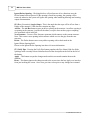
Fabricated Steel Screen - Grates & Covers Tab
Screen Section Number, Description and Actions
(5.) Use in Job A check box indicating that the piece of fabricated steel is being used in the
current job.
Name The user provided name for each grate or cover defined. It is recommended that the
name be unique. Name also appears in the table that makes up the bottom half of the screen.
Model The manufacturer's specification or model number.
Features Items that need to be included in the reports (pick, gasket, import, domestic, bolt
down, etc.).
Notes Additional miscellaneous information about the grate, or cover.
Marking Identifying text stamped on or cast into the grate or cover.
Weight The weight, in pounds, of the grate, or cover.
ADA A check box to show whether the grate is compliant with the Americans with
Disabilities Act.
Graphic Height The height from the bottom of the frame to the top of the cover or grate.
This will be displayed in the Elevation View Screen and any reports that show the elevation
view.
By Others When selected, the part in question will be excluded from the BOM reports.
Please note this is a company specific feature and may not be enabled on your version.
Clear Opening Size The opening size of the fabricated steel that fits on the frame or ring.
Traffic Rating Gives options for traffic ratings. These may be Standard, H20, or Pedestrian.
© 2008 FBE Associates, Inc.
Screen Descriptions
2.5
17
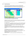
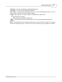
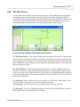
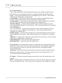
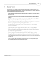
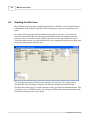
Flow Tree Screen
The Flow Tree Screen controls the loaded job. The structures are added, named, and
positioned hierarchically on this screen. The user can see the list of structures either
alphabetically or organized by flow order. Individual structures and groups of structures can
be selected for BOM and drawing reports from this screen by using the check boxes.
Screen Section Number, Description and Actions
(1.) Job - Each Job shown in the Flow Tree screen has a Job Icon before it. The system has
the ability to work on more than one job at the same time. Dividing a large job into smaller
parts is a handy way to organize large projects.
(2.) Alphabetical List - The Alphabetical List by Job (access via the Arrow Button described
below) display shows an alphabetical list of structures organized by job. This view allows the
user to quickly and easily find specific structures when partial job outputs are being created,
changes need to be made to a specific structure, or other activities relating to a specific
structure need to be carried out.
Arrow Button - By using the Arrow Button the user has the option of displaying the
Alphabetical List by Job. Select from the drop down box placing the alpha list vertically to
the right of the flow tree, horizontally at the bottom of the flow tree or the alpha list can be
turned off.
(3.) Drainage List by Job -This Drainage List by Job display shows the drainage tree
hierarchically. Structures are shown as they connect to each other in the site plan.
Flow Tree - All Structures for a job are shown in the Flow Tree. The structure name consists
of the name provided by the user and the structure type.
Structure Name - Structure Name can be added here or in the Structure Screen.
Selecting a Structure - To select the current structure, click on the structure name.
© 2008 FBE Associates, Inc.
18
MH Pro! User Guide
Re-organizing the Structures - The Flow Tree may be reorganized, or re-parented, by
dragging (click and hold) a structure to a new location and dropping (release the mouse
button) the structure in its new location.
Check Box - Each entry in the Flow Tree has a check box to allow the user to select a subset
of the entire job when creating output documents and Reports. The system does not require
unique names for each structure, but it is highly recommended that the user uniquely name all
structures.
(4.) Add - The Add button adds a structure upstream of the currently selected structure in the
Flow Tree. The user can immediately name the structure as desired.
Rename - The Rename Function gives the user the ability to rename the currently selected
structure. Press enter to commit the new name. It should be noted that a warning is given to
the user if the new name is not unique within a job.
Delete – Delete removes the currently selected structure from the Flow Tree. Please note that
this operation cannot be undone.
© 2008 FBE Associates, Inc.
Screen Descriptions
2.6
19
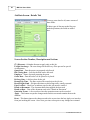
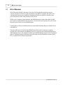
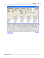
Job Data Screen
The Job Data Screen allows
the user to enter the name of
the job and other associated
data about the job. In the
Contractor List tab a database
of contractors is maintained.
The Details Tab contains many
fields for other data about the
job.
If there is no field in MH Pro!
for data about your operations,
it can be added in the Details
Tab.
Screen Section Number, Description and Actions
(1.) Job Data:
Job Name - The user enters the name of the new job here. This field can also be used to
rename an existing job.
Number - A number representing the job.
Location - Two lines of free text information about the location of the job.
Agency - Usually a description of the governmental agency overseeing the job.
Engineer - The name or names of the engineers that are involved with the job.
(2.) The following Contractor Data can be entered:
Name, Contact, Address, City, State, ZIP, Phone Number and Fax Number can be added
in these fields.
Status - Shows whether the contractor is in the Contractor List or not.
Contractor Tab maintains the data for each contractor entered. If the Contractor for this job
is in the list then only the “Use?” box in the Contractor Tab needs to be checked to populate
the Contractor Data fields.
© 2008 FBE Associates, Inc.
20
MH Pro! User Guide
Job Data Screen - Details Tab
You may enter data for all, some or none of
these fields.
If other types of data are needed for your
needed operations, the fields are added
here.
Screen Section Number, Description and Actions
(3.) Discount - A blanket discount to apply only to this job.
Freight Surcharge - The extra charge for the delivery of the precast for special
circumstances.
Quote Date – Date the quote was prepared or delivered.
Bid Closing Date – Last day the bids can be delivered.
Employee – Name of person preparing the quote.
Order Date – Date the order is to be placed or is placed.
Delivery Date - A delivery date for the job.
Round Trip Time – The time required for round trip to the job site.
Road Weight Limit – Weight restrictions on delivering trucks, usually seasonal.
Pipe Certified – Check box to indicate pipe for this job must be certified.
Based on Document – The document name that supplied the data used.
Based on Date – Date of the document used as the “Based on Document”
Quotation Terms – A free text box where the quotation terms can be recorded.
Apply – This button accepts the changes made on this screen and commits them to the
database.
Reset – This button ignores the changes made to the screen since the last Apply was issued or
from just invoking the screen. Once reset, previous values prior to any changes are returned.
© 2008 FBE Associates, Inc.
Screen Descriptions
2.7
21
Job Screen
This is the screen
that you use to start
working on an
individual Job.
Jobs and Reference
Jobs are created
and loaded by use
of this screen.
Existing jobs can
have their names
edited here and be
deleted.
Screen Section Number, Description and Actions
(1.) Jobs – This Tab is used to select or create Jobs that will contain the structures you will
enter data for and create.
Loaded? is the column where “Loaded” is placed for each job that has been loaded into
MH Pro!. If the selected job is loaded, the leftmost button will display Unload Job, otherwise
it will be Load Job (See Section 2 for Load Job). The heading can be clicked on to sort by the
records in this column.
Contractor Name -The name of the contractor is input in the Job Data Screen for each job
and displayed here. The heading can be clicked on to sort by this field.
Job Name - A list of the jobs (input in the Job Data Screen) currently in the system is shown
here. The heading can be clicked on to sort by this field.
Structure Count - The number of structures in each job is listed here.
Reference Jobs – This Tab is used to select or load Reference Jobs.
(2.) Load Job (or Unload Job) by selecting the job and then pressing this button. The job
will then be added or removed, respectively, from the Flow Tree.
New Job -This button creates a new job to be added to the system and opens the Job Data
Screen. The user may then give the job a name and add additional information about the job
in the Job Data Screen.
Edit Job Data - This button, when clicked, opens the Job Data Screen to edit the job.
Delete Job - Pressing this button permanently removes the selected job from the application
database. A pop-up warning will be shown to the user, but if the user chooses to remove the
job it cannot be recovered.
© 2008 FBE Associates, Inc.
22
2.8
MH Pro! User Guide
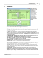
Link Data Screen
This screen provides a way of updating multiple Frame/Ring, Grate/Cover, and Pipe structure
entries at one time for both linked and unlinked data. Unlinked data occurs when an entry's
underlying library definition is changed from its original state. For example, the height of a
Frame is changed from 3" to 4". When this occurs, the entry is unlinked from its library
definition and will continue to be unlinked until the entry is selected again and saved. For a
big job this could require extensive interrogation to determine the affected structures and
many gestures.
Screen Section Number, Description and Actions
(1.) Get Data For
Current Structure In Flow Tree - This option will affect only the currently selected
structure.
All Checked Structures in Flow Tree - This option will affect all checked structures in the
Flow Tree.
Current Job in Flow Tree - This option will affect the currently selected job.
All Structures in Flow Tree - This option will affect the entire Flow Tree.
(2.) Filter By
All - By selecting all, both linked and unlinked data is shown.
Select Types - By selecting Select Types you can chose from Unlinked, Linked (Not Used In
Job) and Linked (Used In Job).
(3.) For each type of data in the four tabs
© 2008 FBE Associates, Inc.
Screen Descriptions
23
Job Name - The job containing the linked/unlinked data.
Old Value - The value of the linked/unlinked data.
New Value - A drop down list of library names in use. For Frame/Ring and Grate/Cover, the
Name is shown. For Pipe, the Hole Name is shown.
Legend - the symbols #,* in front of data in fields indicate certain status.
# - Indicates data up to date.
* - Indicates library data has been changed.
Apply – This button accepts the changes made on this screen and commits them to the
database.
Reset – This button ignores the changes made to the screen since the last Apply was issued or
from just invoking the screen. Once reset, previous values prior to any changes are returned.
© 2008 FBE Associates, Inc.
24
2.9
MH Pro! User Guide
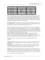
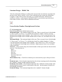
Main Screen
The MH Pro! user interface contains a number of icons that can be used to launch other
screens within the application. There is also a menu bar at the top of the screen that allows the
user to launch screens and perform other functions within MH Pro!
Screen Section Number, Description and Actions
(1.-A) The File menu allows the user to perform a number of standard Windows functions.
Print Setup configures MH Pro! for all its printing actions.
Print Form prints the active screen.
Print Workspace prints the entire MH Pro! user interface.
Copy Form Image to Clipboard allows the user to take a picture of a single screen and paste
it into another document.
Copy Workspace Image to Clipboard allows the user to take a picture of the entire MH Pro
user interface and paste it into another document.
Exit quits the application.
(1.-B) The Screens menu will allow you to launch each screen just as the icons described
below. This list is presented in alphabetical order to make the screens easier for the new user
to find.
(1.-C) The Options dropdown lets you set the on-screen location of the Icons for the MH
Pro! windows.
© 2008 FBE Associates, Inc.
Screen Descriptions
25
(1.-D) The Help section contains:
A User Manual that provides a complete On-line set of descriptive materials about using MH
Pro!
Release Notes is a list of the changes and additions to MH Pro! since it became a viable
commercial product.
Remote Support is a button that allows you to share the control of your MH Pro! Session
with an FBE customer support engineer.
About gives the version number of your current version of MH Pro! and the contact phone
numbers for support and an additional route to Remote Support.
(2.) Main Screen Working Area This section is the main display area for MH Pro! Any or
all of the screens that MH Pro! users work with are displayed here as needed. Usually there
are two to four screens in use, but the number and configuration is determined by the user.
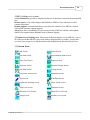
(3.) Screen Icons
Job Screen
Status Screen
Job Data Screen
Miscellaneous Items Screen
Flow Tree Screen
Reports Screen
Structure Screen
Structure Design Screen
Site Plan Screen
Pricing Screen
Fabricated Steel Screen
Migration Screen
Pipe Screen
Link Data Screen
Automatic Stacking Screen
Stack Editor Screen
Plan View Screen
Platforms Screen
Elevation View Screen
Butterfly View Screen
Notes Screen
Rollout View Screen
© 2008 FBE Associates, Inc.
26
2.10
MH Pro! User Guide
Migration Screen
The Migration Tool is used to copy Jobs and Libraries between the current database and an
Archive database. Typically, this screen is used for these common tasks:
1. Transfer data from the database of an older version after installing a new version of
MH Pro!
MH Pro! database are stored with the program by default. The default location
for old MH Pro! databases is therefore, C:\Program
Files\FBE\MHProEZ\Database\
The current database is usually named “MHPro.mdb”. (The .mdb extension
may not be visible depending on your computer setup.)
The database from previous MH Pro! installations are named “MHPro.1.mdb”,
“MHPro.2.mdb”, etc. The MHPro.1.mdb is from the most previous version of
MH Pro! that was installed. Databases with larger numbers are from older
versions of MH Pro.
2. Create a new database that MH Pro! can use as its current database.
3. Create a new database that can store copies of MH Pro! Jobs (but cannot be used as
MH Pro!'s current database).
4. Copy jobs from the current MH Pro! database to an archive database.
5. Retrieve jobs from an archive database and place them into the current database.
•
•
•
© 2008 FBE Associates, Inc.
Screen Descriptions
27
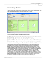
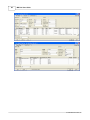
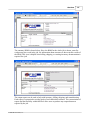
Migration Screen - Import from Archive Tab
Screen Section Number, Description and Actions
(1.) Database Locations
Current Database – The complete path to the database that is being used for the current MH
Pro! session.
Archive Database – Opens the file selection dialog for the Archive source database. After a
database is selected as the Archive database, the data grid in the Copy Jobs To Current frame
will display pertinent data about the jobs so that they may be located and selected for
copying.
(2.) Import From Archive Tab
Copy Libraries To Current – Check the boxes of the libraries that will be imported from the
source database. Press Copy Libraries to transfer the selected library data.
Archive Record Counts – Shows the number of records in each table of the Archive
database (information only).
Copy Libraries – Copies the checked library data from the Archive database to the current
database.
(3.) Copy Jobs to Current
Jobs (and/or Reference Jobs) in the archive data base can be migrated to the current database.
Copy All Non-Ref. Jobs – Copies all jobs that do not have an X in the Ref cell to the current
database. Note that copying jobs takes up to 10 seconds per structure, so Copy All Non
Reference Jobs may take a long time.
Copy Selected Jobs – Copies selected Jobs. Jobs can be selected by left mouse click in the
record selector to the left of the Job Name. The line will remain highlighted if it has been
selected. Multiple Jobs can be selected by holding the Ctrl key down while left clicking the
record selector to the left of the job name.
© 2008 FBE Associates, Inc.
28
MH Pro! User Guide
Migration Screen - Export from Archive Tab
Screen Section Number, Description and Actions
(4.)Export Tab
The functions in Export are similar to Import.
Copy Libraries To Archive – Check the boxes of the libraries that will be exported to the
archive database.
Archive Record Counts – Shows the number of records in each table of the current database
(information only).
Copy Libraries – Copies the checked library data from the current database to the archive
database.
Copy Jobs to Archive
All or a portion of the Jobs or Reference Structures in the current data base can be migrated to
the archive database.
Copy All Non-Ref. Jobs – Copies all jobs that do not have an X in the Ref cell to the current
database. Note that copying jobs takes up to 10 seconds per structure, so Copy All Non
Reference Jobs may take a long time.
Copy Selected Jobs – Copies selected Jobs. Jobs can be selected by left mouse click in the
record selector to the left of the Job Name. The line will remain highlighted if it has been
selected. Multiple Jobs can be selected by holding the Ctrl key down while left clicking the
record selector to the left of the job name.
© 2008 FBE Associates, Inc.
Screen Descriptions
2.11
29
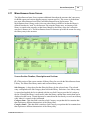
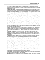
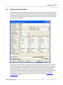
Miscellaneous Items Screen
The Miscellaneous Items Screen captures additional data about the structure that’s necessary
for BOM reports and various shipping reports (custom specific). This screen is divided into
two parts; Miscellaneous Item Library and Miscellaneous Items for Structure. The
Miscellaneous Item Library works just as any other library in MH Pro! in that the library is
defined first then its “used” by the structure. By using the library entry, an instance of the
library is copied to the structure so that future changes to the library entry don’t affect the
structure’s instance of it. The Miscellaneous Items for Structure provides the means for using
the library entry in the structure.
Screen Section Number, Description and Actions
(1.) This section of the screen consists of library filters for use with the Miscellaneous Items
Library. The filters filter library entries and seed new library entries.
Sub Category - A drop down list that filters the library by the selected entry. The selected
entry corresponds to the Sub Category data field in the library. Each time a new library entry
is created and applied, the list is updated with the new Sub Category provided it’s unique to
the list. Filtering the library is most useful when the library contains more entries than can be
displayed on the screen. Textual data may be entered into the list directly to seed a new library
entry when it’s created via the Add button.
Category Item - This data field is similar to Sub Category except that this list contains data
that represents a different characteristic of the library entry.
Category Item2 - This data field is similar to Sub Category except that this list contains data
that represents a different characteristic of the library entry.
© 2008 FBE Associates, Inc.
30
MH Pro! User Guide
Hierarchical Filtering - A check box for controlling whether data in the drop down lists,
above, is grouped in hierarchical order from left to right. That is to say that the library
contains a row that has a Sub Category, Category Item, and Category Item2 that matches the
filter selections.
(2.) This section of the screen consists of the Miscellaneous Items Library table and the
associated buttons for maintaining miscellaneous item library entries. The library entry is used
by Miscellaneous Items for Structure to associate a library entry with a structure.
Add – This button creates a new library entry in the table. The new entry is populated with
the values in filters provided the filters are not set to ‘All’. To save time from entering data,
always set the filters to desired values then add the entries. If the filters don’t contain data,
then save at least one library entry by selecting the Apply button, then create any remaining
entries by first setting the filters, then adding them. The new entry is not actually saved to the
database until the Apply button is selected.
Delete – This button deletes the library entry from the table. The deleted library entry is not
actually removed from the database until the Apply button is selected.
Sub Category – A data field that describes a characteristic of the item - typically the type of
item. The user has full control over the values in this field. Careful planning is recommended
in order to properly define the values because the Category Item and Category Item2 data
fields are coupled with this field to generate a unique set of characteristics that define the
library entry both for the library and Billing Screen. Once the library changes are applied, the
library entry is added to the Billing Screen. NOTE: The same combination of Sub Category,
Category Item, and Category Item2 is used to identify the library entry on the Billing Screen.
For instance, in the example screen above, there are 2 library entries for aluminum ladders.
One entry has a Category Item2 of 5’ (5 feet) and the other 10’. If the ladders in general can
be described by an item type (Sub Category = Ladder), material type (Category Item =
Aluminum or some other material), and length in feet (Category Item2 = 5’, 10’, and other
lengths), then no more data is necessary to uniquely describe the ladders. If for some reason
another characteristic is required, say for example the ladder’s weight capacity, then the
weight capacity would have to be combined with one of the existing characteristics (Sub
Category, Category Item, or Category Item2). The most likely candidate for this case would
be Sub Category or Category Item because including the weight capacity with the length
(Category Item2) does not blend/read well.
Category Item – This data field is Similar to Sub Category except that this field contains data
that represents a different characteristic of the library entry.
Category Item2 – This data field is similar to Sub Category except that this field contains
data that represents a different characteristic of the library entry.
Product ID – An alphanumeric string typically used in accounting. The user has full control
over the data values in this field.
Description – A part description for the item. The user has full control over the data values in
this field.
Unit – A unit of measure that associates with the Unit List Price. The user has full control
over the data values in this field. Typical values could be: ‘ea.’ for each piece, ’12 pk’ for a
package of 12 pieces, or some other desired value.
Unit List Price – The retail price of the item entered as a numeric value.
© 2008 FBE Associates, Inc.
Screen Descriptions
31
Priced? – A flag to determine whether miscellaneous items are reported on the Status Screen
as not having a price. The field supports two values which are ‘Priced’ and not priced
(characterized by an empty field). When the item is Priced, the Status Screen won’t generate a
line for an item that doesn't have a Unit List Price. Otherwise, if the item is empty, then the
Status Screen will generate a line for non priced items. This field is locked down to mouse
selection only. Selecting the left mouse button toggles the data value between Priced and
empty each time the button is selected.
Hide? – A flag to determine whether miscellaneous items are included with a quotation
report. The behavior of how the item is hidden from the report depends on the precaster’s
quoting process. This field supports two values which are ‘Hide’ and not hidden
(characterized by an empty field). This field is locked down to mouse selection only.
Selecting the left mouse button toggles the data value between Hide and empty each time the
button is selected.
Weight – A weight for the item entered as a numeric value.
(3.) This section of the screen consists of the Miscellaneous Items for Structure table and
buttons for maintaining the items. Items are added to the table using the Add Item button, and
item data is changed by entering data directly into the table. NOTE: A structure in the Flow
Tree must be selected in order to use this portion of the screen. Otherwise, this section and its
associated buttons are disabled from being used.
Add Item – This button adds the currently selected library entry to the Miscellaneous Items
for Structure table. If this is the first entry that corresponds to a library entry’s unique
definition (Sub Category, Category Item, and Category Item2), then the Quantity field is set to
1. Otherwise, the Quantity is incremented.
The item isn't actually saved to the database until the Apply button is selected.
Delete Item – This button deletes the miscellaneous item from the table. The item isn't
actually removed from the database until the Apply button is selected.
Quantity – The number of matching items. This field supports only numeric values that may
include decimals.
Product ID – The Product ID from the library entry.
Description – The Description from the library entry.
Note – A special note for output to BOM reports.
Weight – The Weight from the library entry.
© 2008 FBE Associates, Inc.
32
2.12
MH Pro! User Guide
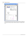
Notes Screen
The Notes Screen
allows the user to
make notes that
pertain to a
structure or a job
within MH Pro!
Notes for
undelivered pieces
are created in the
Stack Editor
screen. The Notes
screen gives the
user the flexibility
to include some,
but not necessarily
all of those
comments in the
reports.
Screen Section Number, Description and Actions
(1.) All Reports - Notes entered into this section will be displayed in all available reports.
(2.) Not Reported - Notes entered into this section will be available but not displayed into
reports.
(3.) Shop Only - Notes entered into the Shop Only section will be displayed and available
only in the shop type reports.
(4.) Submittal Only - Notes entered into the Submittal Only section will be displayed and
available only in submittal type reports.
(5.) Quotation Elements - This section deals with company specific features and may or
may not be available with your version of MH Pro! See Special Topics – Quotation.
(6.) Other – Additional data that can be included on reports is entered into this section. This
data includes Delivery Date, Pipe Notes and Based on Sheet data.
(7.) Apply – This button accepts the changes made on this screen and commits them to the
database.
Reset – This button ignores the changes made to the screen since the last Apply was issued or
from just invoking the screen. Once reset, previous values prior to any changes are returned.
© 2008 FBE Associates, Inc.
Screen Descriptions
2.13
33
Pipe Fittings Screen
The Pipe Fittings Screen captures additional data about the structure’s downstream pipe that’s
necessary for BOM reports and various shipping reports. The downstream pipe is typically
composed of straight pipe and other pieces of pipe (elbows, increasers, reducers, tees, etc.),
these are implemented in MH Pro! as pipe fittings. For pre-casters who do not sell pipe this
screen has little value. However, for those that do, this screen will be useful in capturing pipe
fitting data. This screen is divided into two parts; Pipe Fittings Library and Pipe Fittings for
Structure. The Pipe Fittings Library works just as any other library in MH Pro! in that the
library is defined first then it’s used by the structure. The Pipe Fittings library is different
from other libraries in MH Pro! in that it doesn’t require a “Use” field because the library
consumer, the structure, is tracked on this screen along with the library. By selecting the
library entry, an instance of the library is copied to the structure so that future changes to the
library entry do not affect the structure’s instance of it. The Pipe Fittings for Structure
provides a means for maintaining the structure’s library entries or pipe fittings.
Definitions, descriptions and Actions
(1.) This section of the screen consists of library filters used in conjunction with the Pipe
Fittings Library. These filters filter library entries and seed new ones.
Fitting Type – A drop down list that filters the library by the selected entry. The selected
entry corresponds to the Fitting Type in the library. Each time a new library entry is created
and applied, the list is updated with the new fitting type provided it’s unique to the list. By
default, this list is composed of the following fitting types: Elbow, Increaser, Reducer,
Transition, Cored Tee, Tee, Wye, Cap, Plug, and Pipe. Filtering the library is most useful
when the library contains more entries than can be displayed on screen. Textual data may be
entered into the list directly to seed a new library entry for creation via the Add button.
Selecting a fitting type also enables or disables the Set Labels button (see below for more
details.)
Parameter 1 – A drop down list that filters the library by the selected entry. The behavior of
this filter is similar to the Fitting Type filter except that this filter corresponds to the
Parameter 1 field in the library, and no default set of data for the list exists because this list is
composed of a user defined characteristic for the Fitting Type (see Section 2 for more details.)
Parameter (2-9) – A drop down list similar to Parameter 1 except that this filter corresponds
to the “Parameter nth” field in the library, where nth is a whole number from 2 to 9. At this
point one wonders, “why are so many parameters necessary?” Keep reading and Section 2
should shed some light on this.
Hierarchical Filtering - A check box for controlling whether data in the filters above, is
grouped in hierarchical order from left to right. That is to say, the library contains a row that
has matching data for the corresponding filters in hierarchical order from left to right.
Set Labels – This button provides a method for maintaining user specified labels, by fitting
type, for Parameters 1 through 9. This button is disabled when the Fitting Type is set to “All”
© 2008 FBE Associates, Inc.
34
MH Pro! User Guide
and it’s enabled for all other fitting types. Once selected, each parameter’s label is replaced
with a text field to allow label changes. The text fields and this button are highlighted light
blue to denote that the change mode is in effect. With the text fields active, enter labels for
one or more parameters. As each label is changed, the corresponding parameter’s heading in
the library table is also change to the entered label. The changed label is saved to the screen,
but not to the database until the Apply button is selected
Specifying a label for a parameter has its advantages in that it dynamically creates a data
characteristic for the field in which the parameter associates to in the library. Therefore, each
fitting type can have its own set of data characteristics for each parameter filter. For example,
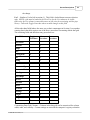
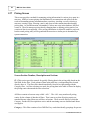
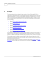
the following table contains a minimum set of parameters for defining Pipe and Elbow fitting
types.
Filter Control
Pipe Filter Setting
Elbow Filter Setting
Parameter 1
12”
RCP C
Parameter 2
RCP C
12”
Parameter 3
Round
135 deg.
Parameter 4
Round
Notice that the data for each fitting type represents a very different characteristic for each
parameter. In the case of a Pipe, Parameter 1 defines the pipe size, where as for the Elbow,
Parameter 1 defines the pipe material.
The resulting dynamic labels might be defined as:
Filter Control
Pipe Label Setting
Elbow Label Setting
Parameter 1
Size
Material
Parameter 2
Material
Size
Parameter 3
Shape
Bend Angle
Parameter 4
Shape
The above parameters were deliberately organized this way to illustrate the capability of
dynamic labels. Although this is perfectly acceptable, FBE doesn’t recommend structuring
data this way because it promotes inconsistent data characteristics for each parameter which
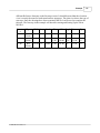
result in cumbersome filter selections. A more appropriate organization of labels is the
following:
© 2008 FBE Associates, Inc.
Screen Descriptions
Filter Control
Pipe Label Setting
Elbow Label Setting
Parameter 1
Size
Size
Parameter 2
Material
Material
Parameter 3
Shape
Shape
Parameter 4
35
Angle
In this case, both fitting types have matching data characteristics for parameters 1 through 3.
However, the Bend Angle characteristic for Parameter 4 probably needs changing because
other pipe fittings will undoubtedly have similar characteristics that don’t match the Elbow’s
angle; pipe fittings with non standard characteristics should be relegated for later parameters
to improve efficiency in entering data. Other characteristics could be the type of joint (spigot
vs. bell), the opening size for a tee or vee, and many more.
(2.) Fitting Type - This section of the screen consists of the Pipe Fittings Library table and
the associated buttons for maintaining pipe fitting library entries. The library entry is used by
Pipe Fittings for Structure to associate a library entry with a structure.
Add – This button creates a new library entry in the table. The new entry is populated with
the values in the filters provided the filters aren’t set to ‘All’. To save time in entering data,
always set the filters to desired values then add the entry. If the filters don’t contain data, then
save at least one library entry by selecting the Apply button, then create any remaining entries
by first setting the filters, then adding a new library entry. The new entry is saved to the table,
but not to the database until the Apply button is selected.
Delete – This button deletes the library entry from the table. The deleted library entry is
deleted from the table, but not from the database until the Apply button is selected.
Copy – This button copies the selected library entry to a new library entry. The copied library
entry is saved to the table, but not to the database until the Apply button is selected.
The following Data Entry Procedure are used when entering data in the library table
(datagrid).
Toggle Procedure – To toggle data, move the mouse pointer into the desired field then select
the left mouse button to toggle the data from a set state (a keyword) to a not set state (an
empty field)
Enter Procedure – To enter data, move the mouse pointer into the desired field. Double
click the left mouse button which invokes a cursor for entering data. Select the tab key or
enter key to accept the change. Select the escape key to cancel the change.
Fitting Type – A data field that defines the type of pipe fitting. Use the Enter Procedure to
change data. NOTE: Due to the method for modeling (pipe and connector combinations) pipe
libraries in MH Pro!, no listing of pipes exists to expedite the entry of data for a straight pipe
fitting. If a straight pipe is desired, then select a fitting type of “Pipe” or add a new fitting
type, then supply the remaining pipe fitting fields.
© 2008 FBE Associates, Inc.
36
MH Pro! User Guide
Product ID – An alphanumeric string typically used in accounting. Use the Enter Procedure
to change data.
Description – A part description for the pipe fitting. Use the Enter Procedure to change data.
Weight – A weight entered as a numeric value. Use the Enter Procedure to change data.
Pipe Length – A pipe length for the pipe fitting. Use the Enter Procedure to change data.
Parameter 1 – This data field describes a particular characteristic of the pipe fitting. Careful
planning is recommended in order to define the values for this field because the fitting type
and parameters 2 through 9 are coupled with this field to generate a unique set of
characteristics that define the library entry for both the library and the Billing Screen. Once
the library changes are applied, the library entry is added to the Billing Screen. Use the Enter
Procedure to change data.
Now let’s return to the question in Section 1, “why are so many parameters necessary?” This
is best answered by the fact that there are host of characteristics that each precaster uses for
describing pipe fittings. Some pipe fittings are easily defined by a few characteristics like
material, size, and shape and others aren’t as in “an elbow tied on top at the spigot end.” To
capture all or most of the characteristics so that similar ones are entered once and provide
easy selection for other pipe fittings, the screen needs many fields to organize the data for
each characteristic, or the screen needs a static field for each characteristic. Rather than
attempt to determine all the various characteristics for capturing pipe fittings in static fields, it
’s just as effective to provide a suite of fields, parameters, to let the precasters control the
organization of characteristics. This way precaster can tailor pipe fittings to fit their business
needs.
Parameter (2-9) – This data field is similar to Parameter 1 except that this field contains data
that represents a different characteristic of the pipe fitting.
Unit – A unit of measure that associates with the Unit List Price. The user has full control
over the data values in this field. Typical values could be ‘ea.’ for each piece, ’12 pk’ for a
package of 12 pieces, or some other desired value. Use the Enter Procedure to change data.
Unit List Price – The retail price of the item entered as a numeric value. Use the Enter
Procedure to change data.
Priced? – A flag to determine whether pipe fittings are reported on the Status Screen as not
having a price. This field supports two values which are ‘Priced’ and not priced
(characterized by an empty field). When set to Priced, the Status Screen won’t generate a line
for an item that doesn’t have a Unit List Price. Otherwise, if this field is empty, then the
Status Screen will generate a line for non-priced items. This field is locked down to mouse
selection only. Selecting the left mouse button toggles the data value between Priced and
empty each time the button is selected. Use the Toggle Procedure to change data.
Hide? – A flag to determine whether pipe fittings are included with a quotation report. The
behavior of how the fitting is hidden from the report depends on the precaster’s quoting
process. This field supports two values which are ‘Hide’ and not hidden (characterized by an
empty field). This field is locked down to mouse selection only. Selecting the left mouse
button toggles the data value between Hide and empty each time the button is selected. Use
the Toggle Procedure to change data.
© 2008 FBE Associates, Inc.
Screen Descriptions
37
Customizing Data Grid Columns – Columns in the data grid can be customized for column
width, order, and visibility. Custom settings are stored in the computer’s registry so that the
next time this screen is invoked, the settings take effect in the data grid. To customize a
column or sort a column, use the following procedures:
Column Display Procedure - To customize the display of a column, place the mouse cursor
somewhere in the border of the data grid. Select the right mouse button which displays a
menu of column headings and a checkmark preceding them. Move the mouse up or down in
the list to find the desired column to hide or display. Select the mouse button to toggle the
display of the column on or off in the menu. When the column is displayed, the checkmark
will be visible. Otherwise, the column isn’t visible and the checkmark is empty.
Column Order Procedure – To customize the column order, place the mouse cursor in a
desired column heading near the center (avoid the left and right borders) of the heading. Hold
down the left mouse button and drag the column left or right to a new location. Release the
mouse button to save the change. When dragging to the right, drag the column past the right
border of the column that the dragged column should come after.
Column Width Procedure - To customize the width of a column, place the mouse cursor in
a desired column heading near the right border. Hold down the left mouse button and drag
the mouse to the left or right and the column width will change. Release the mouse button to
save the change.
Restore Column Settings Procedure – Follow the Column Display Procedure and instead of
selecting a column heading, select the ‘Restore Column Headings’ menu. Restore Column
Headings restores all columns to their default settings and removes customized settings from
the registry.
Sort Column Procedure – To sort a column, place the mouse cursor in a desired column
heading near the center (avoid the left and right borders) of the heading. Select the left mouse
button once to sort the column of data. Each time the left mouse button is selected, the
column data toggles between ascending and descending sort order.
(3.) Pipe Fittings for Structure - This section of the screen consists of the Pipe Fittings for
Structure table and buttons for maintaining the fittings and the downstream pipe’s
associated openings at each end. Pipe Fitting data is changed by entering data directly into
the table using one of the Data Entry Procedures in Section 2. NOTE: A structure in the
Flow Tree must be selected in order to use this portion of the screen. Otherwise, this
section and its associated buttons are disabled from being usage.
Definitions, Descriptions and Actions
Add Fitting – This button adds the currently selected library entry to the Pipe Fittings for
Structure table. If this is the first entry that corresponds to the library entry’s unique
definition (Fitting Type, Parameter 1, …Parameter 9), then the Quantity field is set to 1.
Otherwise, the Quantity is incremented.
The item isn’t actually saved to the database until the Apply button is selected.
Delete Fitting – This button deletes the pipe fitting from the table. The item isn’t actually
© 2008 FBE Associates, Inc.
38
MH Pro! User Guide
removed from the database until the Apply button is selected.
Add Unique – This button adds the currently selected library entry to the Pipe Fittings for
Structure Table. No check is made to see if a similar entry exists because the purpose of this
button is to add a unique entry. This is most useful when the exact layout of the pipe fittings
that make up the downstream pipe is required. That is to say, two exact pipe fittings exist, but
each occupies their own row in the table. If the exact layout isn’t required, then use the Add
Fitting button.
\/ (Move Down) – This button moves the currently selected entry down in the table by
switching rows with the one below it. This allows the user to order the pipe fittings to
generate the exact layout of pipe fittings in the downstream pipe. The pipe fittings are
ordered in the table, top to bottom, from the current structure to the downstream structure
/\ (Move Up) - This button is similar to Move Down except that the entry is moved up.
Located directly above and below the Pipe Fittings for Structure table are groupings of
opening fields that correspond to the Hole Names for the current structure and downstream
structure. The “From: Structure Name” label represents the opening for the current
structure and the “To: Structure Name” represents the opening for the downstream structure.
These fields are included on this screen to provide an alternate screen for maintaining the
Hole Name on the Structure screen and the ability to manipulate the number of pipe segments
for each end that contribute to the downstream pipe’s layout. The opening fields are:
Hole Name – A drop down list of Pipe Library entries for maintaining the pipe connection.
Pipe Length – The pipe length associated with the Hole Name. NOTE: The intent of this
field is for informational purposes in calculating the total length of pipe associated with the
Hole Name. Although, this pipe length can be changed, FBE prefers that any changes are
made in the Pipe Library first then the Hole Name is re-selected.
Qty – The number of pipe lengths for the Hole Name. If the straight pipe between the From
side, this structure, and the To side, the downstream structure, is the same, then simply enter
the number of desired segments in the Qty field this structure.
Located just below and to the right of the Pipe Fittings for Structure table is Pipe Fitting
Details which is a summary of the calculation used to determine how closely the total length
of pipe fittings matches the downstream distance. The inputs to this summary are:
Downstream Dist. – The downstream pipe distance.
Pipe Fitting Dist. – The total pipe fitting distance that includes the total length of pipe from
both Hole Names and the pipe fittings in the table.
Residual Dist/Additional Dist. – The result of subtracting the Pipe Fitting Dist. from the
Downstream Dist. If the Pipe Fitting Dist. is less that the Downstream Dist, then Residual
Dist. is displayed. Otherwise, Additional Dist. is displayed.
Adjust Qty for Residual – This button automatically adjusts the Qty of pipe segments
required to fill in any residual distance with the pipe associated to the current structure’s Hole
Name. If no residual exists, then no action occurs and the Qty is unchanged.
The following are data fields that make up the Pipe Fittings for Structure table.
Quantity – The number of matching pipe fittings. This field supports only numeric values
that may include decimals. Use the Enter Procedure to change data.
© 2008 FBE Associates, Inc.
Screen Descriptions
39
Fitting Type – The fitting type from the library entry. NOTE: this is a read only field and
cannot be changed.
Product ID – The Product ID from the library entry. Use the Enter Procedure to change data.
Description – The Description from the library entry. Use the Enter Procedure to change
data.
Note – A special note for output to BOM reports. Use the Enter Procedure to change data.
Pipe Length – The pipe length from library entry. Use the Enter Procedure to change data.
Weight – The Weight from the library entry. Use the Enter Procedure to change data.
(4.) Apply – This button accepts the changes made on this screen and commits them to the
database.
Reset – This button ignores the changes made to the screen since the last Apply was issued or
from just invoking the screen. Once reset, previous values prior to any changes are returned.
© 2008 FBE Associates, Inc.
40
2.14
MH Pro! User Guide
Pipe Screen
The Pipe Screen is composed of three tabs for maintaining pipes, ends, and connectors. It is a
good idea to understand the Pipe Library Tab before reviewing the End and Connector tabs.
Pipe Screen - Pipe Library Tab
The Pipe Library Tab provides a method for maintaining pipe library entries and specifying
pipes for “Use” in a job. A pipe library entry defines a set of pipe and connector information
that’s identified by its Hole Name. A pipe that is used in the job makes the Hole Name
available for selection in the Structure Screen in the Hole Name field of an opening.
It should be noted that editing a pipe changes the library definition permanently which has the
potential for impacting incomplete jobs. This is because pipes associated to a structure are
not references to the pipe library entry, but instead to a copy of the pipe library definition at
the time it was selected. Therefore, the job could have pipes with matching Hole Names, but
very different library definitions.
Screen Section Number, Description and Actions
(1.) This section provides various controls for entering data in the pipe library (table on
screen, described i n Section 2 below, commonly referred to as a data grid). As selections are
made, once control passes to another field either by tabbing or selection the left mouse button,
the data in the control is displayed in the table. At this time however, the data isn’t saved to
the database because there could be more changes. To save the data to the database, select the
Apply button which saves the data.
Pipe Library – A tab that groups pipe library information together.
End Library – A tab that groups end library information together.
Connector Library – A tab that groups connector library information together.
© 2008 FBE Associates, Inc.
Screen Descriptions
41
Use In Job? - Controls whether the pipe is available for use in job. Selecting this field
populates the table with a keyword of Use and the Hole Name is made available for selection
in the Structure Screen.
Generate Hole Name – Controls whether the system should generate a Hole Name. When
checked, this field updates with a more descriptive name as fields are populated from left to
right for a row and then continuing to the next row of fields. If the desire is to provide a Hole
Name first and then fill out the fields later, then uncheck this control first, otherwise as
subsequent field are filled in, the desired Hole Name will be overwritten.
By Others – Controls whether the pipe (just the pipe not the connector) is supplied by an
outside source. Selecting this field populates the table with a keyword of ‘Yes/No’. The
result of this selection is used by various reports to omit pipes or flag them as being supplied
“By Others.”
Pipe Material - This field consists of a list of material types for the pipe. The user can choose
from any material type in the list or enter a new material.
Pipe Shape - This field consists of a list of shapes for the pipe based on the Pipe Material
selected. The four pipe shapes are round, elliptical, arch, and box.
Pipe Size - This field consists of a list of sizes for the pipe based on the selected Pipe Shape.
The choices available to the user are the nominal or commonly known diameters of the pipe.
This may not be the actual inner or outer diameter of the pipe. The user can choose from any
pipe size in the list or enter a new size.
Pipe OD – This field consists of a list of Pipe ODs for the Selected Pipe Size. The Pipe OD
field specifies the outer diameter or rise/span of the pipe to be used. If only one Pipe OD
exists, then the field will default to it. The use can choose from a Pipe OD or enter a new
OD.
Pipe Wall - The thickness of the wall of the pipe. This value is (outer diameter - inner
diameter) / 2. The user can accept the calculated Pipe Wall or enter a new wall thickness.
Pipe Rating – This field consists of a list of pipe ratings based on the pipe rating system for
the precaster.
Corrugated – Controls whether the pipe is corrugated for a user specified pipe. Otherwise,
the control is locked out from being changed because the pipe is either corrugated or
non-corrugated. That is to say that you can’t change a corrugated pipe to a non corrugated
pipe or vice versa. Selecting this field populates the table with a keyword of ‘Corrugated’ or
an empty string.
Jacking – Controls whether the pipe is a jacking pipe. When checked, the pipe is jacked.
Selecting this field populates the table with a keyword of ‘Jacking’ or an empty string.
Connecter Type – This field consists of a list of connector types based on the previously
filled in pipe fields. The connector type defines the type of connector for connecting the pipe
to the structure. The user can select a connector type or enter a new one.
Connecter Model – This field consists of a list of connector models based on the selected
Connector Type. The user can select a connector model or enter a new one.
Hole Name - A system generated name for the pipe that’s provided as a selection in the
Structure Screen. The Hole Name changes as additional fields are selected. This field can be
changed by the user provided Generate Hole Name isn’t checked.
Pipe Length – This field consists of a list of pipe lengths based on prior pipe field selections.
The user can select a pipe length or enter a new one.
Weight Per Piece - The weight of for the pipe based on Pipe Length. The user can accept the
© 2008 FBE Associates, Inc.
42
MH Pro! User Guide
weight or enter a new one.
MCAH - The Minimum Concrete Around the Hole, in inches. This is a design requirement
based on the connector, pipe, and possibly other factors.
Hole Size - The system calculated opening size for the connector model.
Hole Type – This field consists of a list of hole types depending on the Connector Type. The
hole types include:
· Cast-In – A cast in connector like A-Lok or Z-Lok
· Dog House Up (DHU)
· Dog House Down (DHD)
· Knockout
· Precision – A booted connection
· Rough
· Foam
· Foam Knockout
The user can select a hole type or enter a new one.
Pipe Location – This field consists of a list of pipe locations for center, bottom, and top of
hole. For added control, a vertical offset field (see field directly to the right of this field) may
be entered to offset the pipe vertically from the selected Pipe Location. The offset field
accepts both positive and negative numbers. When the connector is cast-in or booted, the
location is set to center.
Hole Shape – This field is similar to Pipe Shape except that the selected shape controls hole
shape.
Opening Graphic – This field consists of a list of opening graphics for generating a
particular custom opening in various graphical screens. The opening graphic is an AutoCAD
block file maintained by FBE.
(2.) This section consists of the pipe library table or data grid. As data is entered from
controls in Section (1), the table will display the entered/selected data. In addition to
displaying pipe library data, this data grid allows data to be entered directly into the table
whereas other data grids in MH Pro! block data entry – both the End Library and Connector
Library data grids block data entry except for the “Use” column. The data grid accepts both
data entry and list selections depending on the column of interest. Procedures for entering
data include:
·
·
·
Toggle Procedure – To toggle data, move the mouse pointer into the desired field
then select the left mouse button to toggle the data from a set state (a keyword) to
a not set state (an empty field)
Select Procedure - To select data, move the mouse pointer to the right of the
border for the desired field. Select the left mouse button which displays an arrow
button pointing downward. Select the arrow button which brings up a selection
list. Select an entry. To a new entry, follow the Enter Procedure below.
Enter Procedure – To enter data, move the mouse point into the desired field.
Double click the left mouse button which invokes a cursor for entering data.
Select the tab key or enter key to accept the change. Select the escape key cancels
© 2008 FBE Associates, Inc.
Screen Descriptions
43
the change.
Use? – Similar to Use In Job in section (1). This field is locked down to mouse selection
only. NOTE: a job must be loaded in the Flow Tree for the Use column to be visible.
Otherwise, the Use column is removed because no jobs exist for associating with the pipe
library. Follow the Toggle Procedure above to make changes to this field.
All the other data fields behave the same way as their counterparts in Section (1) except that
entering data in the table requires one of the above procedures for entering data in data grid.
The remaining fields and their data entry procedures are:
Data Field
Toggle
Procedure
Select
Procedure
Hole Name
Enter
Procedure
X
Material
X
X
Shape
X
X
Size
X
X
OD
X
X
Rating
X
X
Wall
X
X
Connector Type
X
X
Connector Model
X
X
Hole Type
X
X
Hole Shape
X
X
Corrugated?
X
MCAH
X
Hole Size
X
Offset
X
Location
X
X
Length
X
X
Weight
X
X
Jacking?
By Others
X
X
Customizing Data Grid Columns – Columns in the data grid can be customized for column
width, order, and visibility. Custom settings are stored in the computer’s registry so that the
© 2008 FBE Associates, Inc.
44
MH Pro! User Guide
next time this screen is invoked, the settings take effect in the data grid. To customize a
column or sort a column use the following procedures:
·
·
·
·
·
Column Width Procedure - To customize the width of a column, place the
mouse cursor in a desired column heading near the right border. Hold down the
left mouse button and drag the mouse to the left or right and the column width will
change. Release the mouse button to save the change.
Column Order Procedure – To customize column order, place the mouse cursor
in a desired column heading near the center (avoid the left and right borders) of the
heading. Hold down the left mouse button and drag the column left or right to a
new location. Release the mouse button to save the change. When dragging to the
right, drag the column past the right border of the column that the dragged column
should come after.
Column Display Procedure - To customize the display of a column, place the
mouse cursor somewhere in the border of the data grid. Select the right mouse
button which displays a menu of column headings and checkmarks preceding
them. Move your mouse up or down in the list to find the desired column to hide
or display. Select the mouse button to toggle the display of the column on or off.
When the column is displayed, the checkmark will be visible. Otherwise, the
column isn’t visible and the checkmark is empty.
Restore Column Settings Procedure – Follow the Column Display Procedure
and instead of selecting a column heading, select the ‘Restore Column Headings’
menu. Restore Column Headings restores all columns to default settings and
removes customized settings from the registry.
Sort Column Procedure – To sort a column, place the mouse cursor in a desired
column heading near the center (avoid the left and right borders) of the heading.
Select the left mouse button once to sort the column of data. Each time the left
mouse button is selected, the column data toggles between ascending and
descending sort order.
(3.) Pipe Material Filter – Filters the pipe library by the filter selection. Entries in this list
correspond to each unique Pipe Material in the pipe library that has been applied to the
database. When a filter is selected, the Pipe Material field is disabled and any subsequent
new library entries get populated with a Pipe Material that corresponds to the filter.
Add - This button creates a new library entry in the table as the last row in the table. Once
the entry is created, data can be entered using controls in section (1) or directly into this table.
The new entry isn’t actually saved to the database until the Apply button is selected.
Delete - This button deletes the library entry from the table. The deleted library entry isn’t
actually removed from the database until the Apply button is selected. Once a pipe library
entry is deleted from the database, the entry is gone and it cannot be retrieved.
Copy – This button copies the currently select library entry to new library entry, but with a
different Hole Name of ‘New Entry #’ where the # sign corresponds to an incrementing
number starting from 0.
© 2008 FBE Associates, Inc.
Screen Descriptions
45
(4.) Apply – This button accepts the changes made on this screen and commits them to the
database.
Reset – This button ignores the changes made to the screen since the last Apply was issued or
from just invoking the screen. Once reset, previous values prior to any changes are returned.
© 2008 FBE Associates, Inc.
46
MH Pro! User Guide
Pipe Screen - End Library Tab
The End Library Tab provides a method for maintaining end library entries (safety aprons,
flared and sloped end pipes) and select specifying ends for “Use” in a job. An end library
entry defines a set of end information that’s identified by its End Name. An end that is used
in the job makes the End Name available for selection in the Structure Screen in the End
Name field for an opening.
From the standpoint of the Structure Screen, an end is similar to a pipe and connector
combination except that the end is a pipe and end combination. This way, when an end is
selected on the Structure Screen, the end behaves just like an opening for a pipe and
connector. See Structure Screen Section 1.
It should be noted that editing an end changes the library definition permanently which has
the potential for impacting incomplete jobs. This is because ends associated to a structure
aren’t references to the end library entry, but instead a copy of the end library definition at the
time it was created. Therefore, the job could have ends with matching End Names, but very
different library definitions.
Screen Section Number, Description and Actions
(5.) Use In Job? - Controls whether the end is available for use in job. Selecting this field
populates the table with a keyword of ‘Use’, and the End Name is made available for
selection in the Structure Screen.
Generate End Name - Similar to Generate Hole Name in the Pipe Library Tab except that
the generated name applies to an end.
Fill Using Hole Name - A list of Hole Names from the Pipe Library Tab that have been
selected for “Use” in job. Selecting a Hole Name from the listing automatically populates the
Pipe Material, Pipe Shape, Pipe Size, and Pipe Length fields.
Pipe Material – Same as the Pipe Material in the Pipe Library Tab.
Pipe Shape - Same as the pipe shape in the Pipe Library Tab
Pipe Size – Same as the Pipe Size in the Pipe Library Tab.
End Type – A list of end types (Flared End, Safety Apron, and Sloped End). The user can
choose an end type or enter one.
Slope – A list of slopes (2:1, 4:1, and 6:1). The user can choose a slope or enter a new one.
Pipe Rating - Same as Pipe Rating in the Pipe Library Tab.
Grate – A check box for controlling whether the end has a trash grate.
Outlet Length – The lay length when the end is used in an outlet application.
Inlet Length – The lay length when the end is used in an inlet application.
End Name – A system generated name for the end that is provided as a selection in the
Structure Screen. The End Name changes as additional fields are selected. This field can be
changed by the user provided Generate End Name isn’t checked.
© 2008 FBE Associates, Inc.
Screen Descriptions
47
Pipe Length – Same as the Pipe Length in the Pipe Library Tab.
Weight Per Piece - The weight of the end.
Pipe Material Filter – Filters the end library by the filter selection. Entries in this list
correspond to each unique Pipe Material in the end library that has been applied to the
database. When a filter is selected, the Pipe Material field is disabled and any subsequent
new library entries get populated with a Pipe Material that corresponds to the filter.
© 2008 FBE Associates, Inc.
48
MH Pro! User Guide
Pipe Screen - Connector Library Tab
The Connector Library Tab provides a method for maintaining connector library entries
specific to a precaster). A connector library entry defines a custom connector for use with the
pipe library. The connector library is identified by its Type and Model fields which
correspond to the Connector Type and Connector Model fields in the Pipe Library Tab.
It should be noted that editing a connector library entry changes the library definition of the
connector permanently which has the potential for impacting incomplete jobs. This is
because connectors associated to a pipe aren’t references to the connector library entry, but
instead a copy of the connector library definition at the time it was created. Therefore, the job
could have pipes with the same Type and Model, but very different library definitions.
Screen Section Number, Description and Actions
Type - This field consists of a list of connector types based on connectors defined in the
database. The connector type defines the type of connector for connecting the pipe to the
structure. The user can select a connector type or enter a new one.
Model - This field consists of a list of custom connector models defined by the precaster. The
user can select a connector model or enter a new one.
Min OD – The minimum pipe outside diameter for the grip range or the connector.
Max OD – The maximum pipe outside diameter for the grip range of the connector.
Pipe Shape – Same as Pipe Shape in the Pipe Library Tab.
Rec. Hole Size – The recommended hole size of the connector.
Rec. Hole Type – This field consists of a list of hole types for a connector. The user can
select a hole type or enter a new one.
Band Width – The width of a connector in contact with the precast for a hole in a round
structure. The band width overcomes the shortcomings of a regular boot in that in provides
more contact with the precast which accounts for the fact that the sides of a hole in a round
structure are further back than the top and bottom portions of the hole.
Grip Proportion – The portion of the band width represented as a decimal number, typically
between .7 and 1, that should be in contact with the precast when the connector is installed.
Corrugated – Controls whether the connector requires a corrugated pipe.
Clamp Number - The product code/number of a steel pipe clamp provided by the connector
manufacturer for a booted connection.
Clamp Count – The number of steel pipe clamps for the booted connector.
PIC – Controls whether the connector requires a pipe in center connection. When checked,
the Pipe Location field on the Pipe Library Tab is set to center. Otherwise, the pipe is
assumed to be capable of being at the bottom, center, bottom, or top of hole.
© 2008 FBE Associates, Inc.
Screen Descriptions
2.15
49
Plan View Screen
The Plan View screen
shows the structure from
the top. This is helpful
when checking the
opening locations for
accuracy. If an opening
has been entered
incorrectly, the error will
be easily noticed when
examining the structure in
this view. Some form of
this view exists on most
shop drawing reports.
Screen Section Number, Description and Actions
(1.) Structure Name - The Structure Name appears in the Plan View title. As different
structures are selected on the Flow Tree or the Site Plan, the Structure Name will change to
reflect the current structure.
ID – The various holes are assigned an ID to be displayed in the Plan View Window.
Bottom – Displays the related information to the sections bottom.
Pipe – Displays the pipe that is being used for the structure.
Connector – Displays the connector method that is being used for the structure/pipe.
Angle – Displays the various angles between the outlet pipe and inlet pipes.
Dist – The distance to the downstream structure is shown for the outlet pipe or the distance to
the upstream structure for inlet pipes.
(2.) Plan View Window - This window displays the Plan View for a structure. Note that the
system also displays opening information including pipe information.
© 2008 FBE Associates, Inc.
50
MH Pro! User Guide
(3.) Zoom Window - This button allows the user to select a window within the Plan View
Window to zoom in on. After pressing this button, the user clicks the upper-left-hand-corner
of an area to zoom in on. Then the cursor is moved to the lower-right-hand-corner of the area
and the user clicks again. The rectangle created by the two mouse clicks is then zoomed to fit
in the Plan View window.
(4.) This section has five controls that affect the view on the screen:
The Piece Selection dropdown allows selection of the piece to be viewed with the complete
Structure as the default.
Two Rotation buttons and an Angular Selection dropdown cause rotation of the view.
The Drawing Format dropdown allows selection of drawing formats that match your Shop
and Submittal drawings.
(5.) Zoom All - The Zoom All button changes the scale of the Plan View window so that the
entire structure is displayed in the window.
© 2008 FBE Associates, Inc.
Screen Descriptions
2.16
51
Platforms Screen
Use of the Platform screen is valid for companies that have provided data to FBE on how they
produce platforms. There are special circumstances where a platform is needed in a structure
for either safety or equipment mounting needs.
(1.) Platform Stack Height – the Working Height calculation will indicate if a platform(s)
is needed for a structure
Platform Placement – placing the radio button determines if the platform will have a manual
or an automatically generated field elevation for the platform.
Snap to std. location checkbox – a check in this box will place the platform at a field
elevation above the base that is equal to the number input in the from bottom field.
(2.) Automatic Elevation
Field Elevation (s) – this is the elevation of the platform that is automatically calculated by
MH Pro!
Manual Elevation
Field Elevation –the field elevation of the platform is entered here.
Note – this note about the platform appears in selected reports based on individual company
requirement.
© 2008 FBE Associates, Inc.
52
2.17
MH Pro! User Guide
Pricing Screen
This screen provides a method for managing pricing information for various piece parts in a
structure. MH Pro! creates pricing data automatically as transactions take place from the
result of demanding pricing information about a structure; invoking a screen; selecting a
structure; creating a pipe; selecting a stack, and a host of other transactions that demand
pricing data. As part information is demanded, if it does not exist in the database, MH Pro!
creates it. The user manages pricing data by changing data or deleting pricing entries, but
creation of data is not supported. Once pricing information is deleted it cannot be retrieved,
but the actual pricing entry will be generated the next time a similar part is demanded by a
system transaction.
Screen Section Number, Description and Actions
(1.) This section provides controls for quickly filtering data in the pricing table based on the
data field for the filter. Each column of data in the table has a corresponding filter located
directly above it. The filters filter data hierarchically from left to right starting with the
Category filter. As filter selections are made, the pricing data in the table is filtered to display
the pricing entries that match the filter selections.
All filters contain at least one entry called ‘<All>’. The <All> entry matches all pricing
entries for the column of data that it filters. That is not to say that all pricing entries are
matched because other filters may still have selections. There are nine filters of which the
Category, Product ID, Description are active and the remaining ones are disabled until future
uses appear.
Category – This filter contains a list of MH Pro! key words that identify groupings for precast
© 2008 FBE Associates, Inc.
Screen Descriptions
53
parts and incidental pieces. For instance, the key word for precast parts is ‘Section’ and for
precast parts generated on a set increment, the key word is ‘Section Varying’. Most other key
words are self-describing.
For example, to filter for just precast parts, select the Section entry.
Product ID – This filter contains a list of MRU (Most Recently Used) filter strings entered by
the user for this filter on various occasions in this screen.
By default, this filter is different from the Category filter because no known set of aggregate
Product IDs exists; each Product ID should be unique. This is okay because this filter creates
a dynamic set of aggregate Product ID entries by allowing the user to enter a filter string. The
filter string filters the pricing table for Product IDs that match the desired string. To enter a
filter string, simply enter a string of characters that are likely to match one or more Product
IDs in the pricing table. The filter string is saved to the computer registry as an MRU filter
string by selecting the Tab key following the entry of the string. Once the tab key is selected,
the filter string is saved as the top most MRU filter string in the list. As more and more filter
strings are entered, the last set of MRU filter strings are moved down in the list and the new
one is put on top. The list is limited to 5 MRU filter strings. Therefore, the sixth MRU filter
string causes the last MRU filter string in the list to be removed.
For example, say the pricing table contains the following Product IDs without the heights in
parenthesis:
·
·
·
·
·
048RISER040 (40”)
048RISER044 (44”)
048RISER048 (48”)
048RISER060 (60”)
048RISER072 (72”)
To filter for just the risers above 39” and below 50”, enter “RISER04” without the double
quotes. The result will be the first three Product IDs because each of these contain the filter
string.
Description – This filter is similar to the Product ID filter except that the MRUs being
tracked are for the Description field, and the list may contain key word entries based on the
selected Category. A key word entry is a high-level term for describing groupings of similar
pricing entries based on the category. If the selected Category has key words for this filter,
then the list will contain a dashed line to separate the MRUs (on top) from the key words
(below).
For example, in the screen above, this filter would have key word entries for Donut, Solid
Lid, Curb Inlet, Flat Lid, Manhole Section, etc.
(2.) This section consists of the pricing table that allows the user to change pricing data.
Category – A keyword for identifying groupings of data and incidental pieces. This field is
for display purposes only and cannot be edited.
Product ID – An alphanumeric string typically used in accounting. The user has full control
over the data values in this field.
© 2008 FBE Associates, Inc.
54
MH Pro! User Guide
Description – A part description for the pricing entry. The user has full control over the data
values in this field.
Priced? – A flag to determine whether a pricing entry is reported on the Status Screen as not
having a price. The field supports two values which are ‘Priced’ and not priced (characterized
by an empty field). When the pricing entry is Priced, the Status Screen will not generate a
line for an entry that does not have a Unit List Price. Otherwise, if the pricing entry is empty,
then the Status Screen will generate a line for non-priced entries. This field is locked down to
mouse selection only. Selecting the left mouse button toggles the data value between Priced
and empty each time the button is selected.
Hide? – A flag to determine whether pricing entries are included with a quotation report. The
behavior of how the entry is hidden from the report depends on the precaster’s quoting
process. This field supports two values which are ‘Hide’ and not hidden (characterized by an
empty field). This field is locked down to mouse selection only. Selecting the left mouse
button toggles the data value between Hide and empty each time the button is selected.
Unit – A unit of measure that associates with the Unit List Price. The user has full control
over the data values in this field. Typical values could be ‘ea.’ for each piece, ’12 pk’ for a
package of 12 pieces, or some other desired value.
Unit List Price – The retail price of the pricing entry entered as a numeric value.
(3.) This section provides a method for pricing entries based on the selected job in the Flow
Tree screen. This way, parts can be marked up or reduced depending on the job.
Custom Unit List Price – The custom retail price of the pricing entry for the selected job.
Note – A note for describing something special about the pricing entry. This note gets output
to BOM reports and a quoting report (depends on the precaster).
(4.) Delete – This button deletes the pricing entry from the table. The entry is not actually
deleted from the database until the Apply button is selected. Once a pricing entry is deleted,
any changes to the entry prior to the deletion are gone forever and cannot be retrieved.
Apply – This button accepts the changes made on this screen and commits them to the
database.
Reset – This button ignores the changes made to the screen since the last Apply was issued or
from just invoking the screen. Once reset, previous values prior to any changes are returned.
© 2008 FBE Associates, Inc.
Screen Descriptions
2.18
55
Reports Screen
The Reports screen
allows the user to
choose the type of
report generated by
MH Pro! Shop
drawings and Bill of
materials (BOM) are
two examples of the
possible reports. The
screen handles all
the options
concerning how
reports are generated
and for which
structures the reports
will be made.
Screen Section Number, Description and Actions
(1.) Select Reports:
Use? - The outputs and reports to be generated by MH Pro! are selected here. A report is
selected by placing a check in the box to the left of the report type.
Report Name - This section displays the various report types.
TOC? - This column allows you to include a Table Of Contents in the report.
Sort 1 - Allows structures to be sorted by certain criteria. See Special Topics - Sorting Uses.
Sort 2 - Works as an additional sorting option after the Sort 1 field criteria.
(2.) Generate Reports For:
Current Structure in Flow Tree - This option creates outputs and reports for the selected
structure.
All Checked Structures in Flow Tree - This option will create outputs and reports for the
structures in the flow tree that have a check in the box to the left of the Structure Name.
Current Job In Flow Tree - This will allow you to select the current job being worked on.
All Structures in Flow Tree - This option creates outputs and reports for the entire Flow
Tree.
(3.) Output Reports To:
Preview in Display - Shows reports on-screen, before producing a printed copy of them.
Print Directly to System Printer - This option sends the reports directly to the printer.
Next - The reports chosen on the screen will be produced by pressing this button.
Previous - This allows you to go back a step if necessary.
© 2008 FBE Associates, Inc.
56
2.19
MH Pro! User Guide
Rollout View Screen
The Rollout View of a structure is most commonly used with round structures and allows for
easy measurement of distances between hole edges.
Screen Section Number, Description and Actions
(1.) This is the view of the structure after it has been displayed in the Rollout View. You can
measure the distance between any two points in a graphics view in MH Pro! See Special
Topics - Measuring in Graphic Views.
(2.) The left button allows the user to select a window within the Rollout View window to
zoom in on. See the Site Plan or Butterfly View screens for instructions on how to use the
Zoom feature. (4.) The right button returns Rollout View to entire screen size.
(3.) This section has five controls that affect the view on the screen:
The Piece Selection dropdown allows selection of the piece to be viewed with the complete
Structure as the default.
Two Rotation buttons and an Angular Selection dropdown causes rotations in the view.
The Drawing Format dropdown allows selection of drawing formats that match your Shop
and Submittal drawings.
© 2008 FBE Associates, Inc.
Screen Descriptions
2.20
57
Site Plan Screen
The Site Plan Screen displays the entire job in a top view. This is helpful when checking the
positioning accuracy of the structures as well as the hierarchy. If the site plan in MH Pro!
matches that of the engineering drawings, the user knows the angle and distance data for each
structure have been entered correctly. The site plan also allows for graphical selection of a
structure for display in the Structure screen by clicking on the structure's name.
Screen Section Number, Description and Actions
(1.) Site Plan Window - This window displays the Site Plan for the entire job. Note that the
system will accurately display structures according to their shape, circles for round structures
and rectangles for box structures. The current structure is blue in the Site Plan. Structures and
pipes with default values (180 degrees from outlet hole to inlet hole and/or 10 feet to the next
structure) appear as yellow.
(2.) Zoom Window - This button allows the user to select a window within the Site Plan
Window to zoom in on. After pressing this button, the user clicks the upper-left-hand-corner
of an area to zoom in on. Then the cursor is moved to the lower-right-hand-corner of the area
and the user clicks again. The rectangle created by the two mouse clicks is then zoomed to fit
in the Site Plan Window.
(3.) Structures View - In this section you can either view "All Strings" which allows you to
view all structures in the job or you can select individual strings.
Viewing Angle - This Section allows you to change your view of the Site Plan.
(4.) Zoom All - The Zoom All button changes the scale of the Site Plan Window so that the
entire layout for the job is displayed in the window.
© 2008 FBE Associates, Inc.
58
2.21
MH Pro! User Guide
Stack Editor Screen
This screen is used to
manually stack a
structure and edit the
stack. Stacks created by
the Automatic Stacking
Screen can be adjusted
and modified to fit
special circumstances.
Screen Section Number, Description and Actions
(1.) Precast Pieces In Stack - The descriptions of your manually stacked pieces will be
displayed in
this area.
Move Up - By highlighting a piece you can move the section up with this button.
Move Down - By highlighting a piece you can move the section down with this button.
Delete - By highlighting a piece you can delete it with this button.
(2.) Height - The height of the highlighted piece.
Center Offset and Center Offset 2 - Center Offset and Center Offset 2 are the inputs that
alter the position of the opening in the top slab to be changed. Allows you the ability to
change or select the center offsets for the selected piece.
Rotation Angle - This allows you the ability to change or select the rotation angle of the selected
piece.
Slab Thickness - This allows you the ability to change or select the slab thickness of the selected
piece.
Pricing Key - A field to input a name for a special piece.
By Others - This check box will allow you to remove the selected piece from the BOM (Bill of
materials). When selected, the part in question will be excluded from the BOM reports. Please note
this is a company specific feature and may not be enabled on your version.
Notes About Selected Piece - You may enter a note about the selected piece in this area.
© 2008 FBE Associates, Inc.
Screen Descriptions
59
(3.) Section Size - Here you select the size for the section you are defining.
Section Type - Once you select a size for your section you can now select from available
section types.
Pieces Available - Based on your selections from the Section Size and Section Type,
available pieces will be show in this section.
(4.) Add Above - This will arrange your piece/section above or on top in Screen Section 1.
Add Below - This will arrange your piece/section below or on bottom in Screen Section 1.
Replace - This will allow you to replace a piece/section in Screen Section 1 with a selected
piece section from Screen Section 3.
Apply - Commits the current changes and selections to the structure.
© 2008 FBE Associates, Inc.
60
2.22
MH Pro! User Guide
Status Screen
The Status Screen provides you with feedback information about the current structure. When
the color-coded errors and warnings have been addressed the structure is ready to be stacked.
Screen Section Number, Description and Actions
(1.) The Status Tab presents an analysis of the inputs made for a structure.
Severity of problems is color-coded: Errors requiring correction appear in red. Information
that may indicate an error, but may also be overlooked, appears in yellow. General
information appears in green. If Quotation is part of your system then blue indicates missing
pricing information.
Messages are generated to explain aspects of the cited problem or to provide additional
information.
(2.) BOM - The BOM Tab displays the bill-of-materials list for the structure based on the
stack chosen in the Automatic Stacking Screen.
(3.) Quote - If your company has the Quotation Add-on then a quote for the structure will
appear here. If not, then no Quote Tab appears.
© 2008 FBE Associates, Inc.
Screen Descriptions
2.23
61
Structure Design Screen
The Structure Design Screen allows the user to create reference structures that will later be
used to speed the data entry process while working on the takeoff for a job. A Reference
Structure is a structure in a Reference Job. The Reference Job is usually created in the general
setup of MH Pro! for a company. It is made available by MH Pro! so the task of defining a
candidate stack can be simplified. Each Reference Structure, in a Reference Job, consists of a
listing of suitable precast pieces that are available for the design of a given type of structure,
for example 3x4 Box, 60” Round Storm, or 48” Sanitary. The Structure Design screen has an
upper section and four tabs.
Reference Data, Structure Data and General Data Tab
The upper section and the first of the tabs are described below: the remaining three tabs
follow with their own display figures and descriptions. The information in these Reference
Structures will be used in creating the candidate stacks of the structures in any job. A structure
must be selected (highlighted on the flow tree) to use any portion of this screen.
© 2008 FBE Associates, Inc.
62
MH Pro! User Guide
Screen Section Number, Description and Actions
(1.) Reference Data Section
This section contains the basic information about a reference structure.
Reference Job - The job name in which the reference structure is stored.
Reference Structure - The name of the reference structure. These names may indicate sizes
and types of structures or geographic locations (or any desired characteristic).
Specification - A freeform field to be shown on shop drawing reports, with typically, a claim
by the takeoff engineer about the specification being met by the structure.
Reference Data Modified - This check box shows if any of the data from the reference
structure has been changed in the current structure.
(2.) Structure Data Section
The basic dimensions of each type of structure is defined in this section.
Opening Size - The top opening diameter or grate size for the manhole or inlet.
Mid3 Size – This reduction zone does not have a typical use, but can be used to handle a
structure with a multi-step reduction.
Mid2 Size – In non-reducing structures this size is typically the structure size. In reducing
structures the Mid2 Size is typically the chimney size of the structure. The reduction zone
associated with the Mid2 Size has additional controls that allow the reducer from the Mid1
Size to this Mid2 Size to be easily constrained to a limited range.
Mid1 Size – In structures with oversized slabs attached to risers, this is the size of the bottom
riser.
Bottom Size - The inside diameter or inside length and width dimensions of the structure
base. In structures with oversized slabs attached to risers, this is the size associated with the
oversized pan. In most structures this is the structure size.
Custom Options
MH Pro! allows non-standard sizes for box and round structures to be used. The dimensions
for these non-standard size structures can be entered in this section.
Opening Size Dimensions and Walls - These cells are only active when “Custom” Opening
Size is selected. These cells define the non-standard dimensions for a custom round or box
structure. Dimensions can be for round (i.e. 48”) or box (i.e. 3’x4’) and Wall is the wall
thickness (i.e. 6”).
Bottom Size Dimensions and Walls - These cells are only active when “Custom” Bottom
Size is selected. These cells define the non-standard dimensions for a
custom round or
box structure. Dimensions can be for round (i.e. 48”) or box (i.e. 3’x4’) and Wall is the wall
thickness (i.e. 6”).
(3.-A) General Tab
The topics in the General tab define additional features of the structure.
Eccentricity Angle – In round structures, this is the angle that the eccentricity (and usually
the steps) will be offset from the protractor zero feature of the structure. In box structures, this
is the direction of a line through the long face of the box.
Step Name – When only one step type is available for use, this field should be set to “Step”.
© 2008 FBE Associates, Inc.
Screen Descriptions
63
When different step types are available, set this to the name of the desired step type.
Steps Required – When Yes or No the function turns steps on or off. When using the “After
Depth” function, steps will automatically turn themselves on or off when the structure depth
exceeds the “After Depth” specified below.
After Depth – When Steps Required is set to “After Depth” this is the depth which triggers
the presence or absence of steps.
Step Offset From Ecc. – Some structures will require that the steps be offset from the
eccentricity of the structure. This normally occurs when a round structure with a box opening
needs steps placed in a corner of the box, rather than the center of the box face. In this case,
the Eccentricity Angle specifies the line through the box face, the Step Offset is the angle
between the center of the box face and the steps.
Box Step Face – In box structures, the Eccentricity Angle specifies the long face of the box.
Box Step Face then places the steps on the appropriate named face.
Box Step Offset of the structure – When building a box structure with no reductions, the Box
Step Offset moves the steps to the side of the box face.
(3.-B) Stacking
The entries in this section define some of the rules that the MH Pro! auto stacking routine
uses to pick pieces for the structure.
Leave Short - A number that reduces the build height to make it possible for contractors to
provide their own adjusting rings in the field. The reduction occurs in the adjustment area
just below the Top of Casting.
Build Tolerance Low - A number that provides a tolerance for determining which candidate
stacks from Auto Stacking are below the Top of Casting by this number.
Build Tolerance High - A number that provides a tolerance for determining which candidate
stacks from Auto Stacking are above the Top of Casting by this number.
Too Tall Behavior - A selection that controls how the stack behaves vertically when the
structure height is increased using the Stack Editor screen. Entries include: Adjust Leave
Short - This selection reduces the stack in the Leave Short region until this region is
exhausted. Once the additional height exceeds the vertical height of the Leave Short region,
the remaining height causes the structure to grow vertically to the point where the precast
exceeds the field elevation of the Top of Casting - Graphically, this is denoted on the
Elevation View by the casting highlighted in red provided the structure includes a casting
graphic.
Lock Leave Short - This selection locks the Leave Short region which causes the base to
increase vertically below the outlet pipe by the additional height. The net effect is that the
base increases in vertical height below the outlet pipe. For a storm structure the additional
height produces a sump effect whereas for a sanitary structure the additional height is
allocated as additional thickness below the channel or, if there is no channel, a second pour is
added to the base floor of the structure.
Lock Frame - This locks the field elevation of the casting which causes the precast vertical
height to exceed the field elevation of the Top of Casting by the additional height.
Graphically, this is denoted on the Elevation View by the casting to be highlighted in red,
provided the structure includes a casting graphic.
© 2008 FBE Associates, Inc.
64
MH Pro! User Guide
(3.-C) Miscellaneous
This section contains all the other incidental items that go into making a finished structure
that either have to be incorporated at the time of casting or added to the finished casting.
Usage - A selection that contains names for describing the type of structure. The selection
entries may be configured on a company basis.
Coating Inside - A selection that contains the various coatings for application inside the
structure. These selection entries may be configured on a company basis.
Coating Outside - A selection that contains the various coatings for application outside the
structure. These selection entries may be configured on a company basis.
Joint Seal (Bottom) - A selection that contains the various joint seals applied to precast
pieces that match the Bottom Size of the structure. These selection entries may be configured
on a company basis.
Joint Seal (Reduced) - A selection that contains the various joint seals applied to precast
pieces above the full size Bottom Size precast pieces. These selection entries may be
configured on a company basis.
Reinforcing Spec. - A selection for reporting where reinforcing information for the structure
is documented in various reports. These selection entries may be configured on a company
basis.
Admixture - A selection that contains the various admixtures for the precast. These selection
entries may be configured on a company basis.
Outside Drop Style - Chooses the style of the Outside Drop.
Inside Drop Style – Chooses the style of the Inside Drop.
(4.) Copy Data - Pressing this button copies every value that can be changed on this screen,
whether it is visible or not at the time, and places the data into a memory buffer (clipboard).
This is usually done to create new reference structures that vary only slightly from the
structure being copied.
Paste Data - Pressing this button after data has been copied to the buffer (clipboard) pastes
the data into another structure. That other structure must be selected from the Flow Tree
screen before the paste command is given.
(5.) Apply – This button accepts the changes made on this screen and commits them to the
database.
Reset – This button ignores the changes made to the screen since the last Apply was issued or
from just invoking the screen. Once reset, previous values prior to any changes are returned.
© 2008 FBE Associates, Inc.
Screen Descriptions
65
Structure Design – Base Tab
This tab contains data defining the base of the structure. Sump, channel, base height data, and
other data relating to the base are specified with the fields on this tab.
Screen Section Number, Description and Actions
(6.-A) The Base Zone has most of the dimensional input for the base of a reference structure.
Minimum Height - The minimum value of the Stacking Zone selected.
Maximum Height - The maximum value of the Stacking Zone selected.
Min. Base Thickness - The thickness of the separate base (cookie) or the floor of the integral
base.
Minimum 2nd Pour - When a secondary pour is required for channels or an extra thick base,
the minimum thickness of that pour must be at least this value. Each base in MH Pro! also has
a Minimum 2nd Pour specified for its manufacturing process. The actual value used for
Minimum 2nd Pour will be the greater of this value and the value for the selected base.
Bottom Type - This field has five possible values: Poured in Field, No Channel, Precast
Channel, Manhole Tee and Channel in Field. Poured in Field specifies that the base will be
poured in field to the height of the Poured in Field Height. No Channel will leave the bottom
of the structure flat. Precast Channels are cast into the base before the base leaves the
precaster's yard. Manhole Tee provides selected Manhole Tee pieces. Channel in Field
indicates that the base will leave the yard without channels, but room will be left in the base
to pour a channel in the field. This differs from Poured in Field in that a precast base is used.
Poured In Field From - Establishes a reference point for measuring the Poured In Field
Height which determines the height of concrete poured above the outlet pipe.
© 2008 FBE Associates, Inc.
66
MH Pro! User Guide
Poured In Field Height - The height of concrete poured above the outlet pipe when a Poured
in Field Base is poured around and above the outlet pipe.
Channel Size - This field has a number of values: Half, Two-Thirds, Full, Double, and any
company specific channel types. These values refer to the depth of the channel as compared
with the height of the outlet pipe.
Channel Bench Slope - A number, typically a decimal number, which is the rise/run from the
edge of the benching from the wall of the structure, that controls the slope of the bench as it
appears in various graphical outputs.
Sump Height - The Sump Height field sets the value for the distance from the top of the base
of the structure to the bottom of the lowest invert in the structure. Some storm structures
require a sump or water cushion below the outlet invert. If a sump is required, enter its depth
here, otherwise enter zero (0) to specify that no sump is allowed or required.
Match Base Key - Includes only those pieces above the base which have the same bottom
opening key as the top opening key on the base.
Flange Ext. Radius - A distance, that specifies an additional radial length beyond the wall of
the structure at the floor, so as to extend beyond the outside of the wall. This applies to both
extended and non extended bases (Flange Ext. Radius is zero for non extended bases).
(6.-B) Available - This list shows all the precast and casting sections that are available to be
used in a stacking. Items from this list can be placed in the Selected list, allowing those
sections to be used in stackings.
(6.-C) Selected - Items placed in this list can be used to stack structures.
© 2008 FBE Associates, Inc.
Screen Descriptions
67
Structure Design – Middle Tab
This tab contains data defining everything in the structure that is not directly associated with
the top or base. Risers, reducers, covers, cones, and other precast sections are defined here.
Using the 13 tabs of this section can become very complex and lead to confusion and
ineffective stacking. A description of the Mid2 Reducer is given below to provide a basic
look at these screens. Please call for additional instruction.
Screen Section Number, Description and Actions
(7.-A) Stacking Zone
Dimensions and style are defined in this section.
Minimum Height – The minimum height of this zone. There are special cases for this height
if “Zero or more” or “Zero or 1” is selected in the Stack Use window. In these cases the
Minimum Zone Height can be left blank. Also if Stack Use is “Zero or more limit each” the
Minimum Zone Height can be left blank. Blank means no limit is set, non-blank enforces the
limit.
Maximum Height - The maximum height of this zone. There are special cases for this height
if “Zero or more” or “Zero or 1” is selected in the Stack Use window dropdown. In these
cases the Maximum Zone Height can be left blank. Also if Stack Use is “Zero or more limit
each” the Maximum Zone Height can be left blank. Blank means no limit is set, non-blank
enforces the limit.
Stack Use – Select from the drop down list the number of these pieces that are allowed in this
structure. The selections are:
Ignore
Select one
Zero/one
Zero/more
Zero/more limit each
One/more
Match Reducer Key – Check box to indicate piece must match key style of the piece below
it.
Reduction Style – Select from the drop down box the reference starting point for determining
the “standard” clearance needed inside the structure.
Reduction Lower Limit – The minimum height above the “standard” clearance height. Note
that the Reduction Lower Limit is to the bottom of the slab – not the bottom of the piece for
Build Height calculations.
Reduction Range – The maximum height above the “standard” clearance height.
© 2008 FBE Associates, Inc.
68
MH Pro! User Guide
(7.-B) Available - This list shows all the precast sections that are available to be used in a
stacking for this type of structure. Items from this list can be placed in the Selected list,
allowing those selected pieces to be used in stackings.
(7.-C) Selected - Items placed in this list can be used to stack structures.
© 2008 FBE Associates, Inc.
Screen Descriptions
69
Structure Design – Top Tab
This tab contains data defining the top of the structure. Casting, adjusting ring, and other data
relating to the top or height adjustment of the structure are specified with the fields on this tab
.
Screen Section Number, Description and Actions
(8.-A) Maximum Height - The maximum allowed height of the adjusting rings.
Top Treatment - A description of the method used to connect the casting to the concrete
structure. A few examples are keyed, notched, or flat concrete and rebar used to reinforce
poured concrete.
Final Reducer Section:
Minimum Height - The minimum required height of the reducing section.
Maximum Height – The maximum height of the reducing section.
(8.-B) Available - This list shows all the precast sections that are available to be used in a
stacking. Items from this list can be placed in the Selected list, allowing those sections to be
used in stackings.
Selected - Items placed in this list can be used to stack structures.
© 2008 FBE Associates, Inc.
70
2.24
MH Pro! User Guide
Structure Screen
The Structure Screen allows users to define each individual structure and its characteristics
for a job. The screen shows the structures directly upstream and/or downstream of the current
structure. Additionally, ad hoc openings in the structure can be created if required by the job.
© 2008 FBE Associates, Inc.
Screen Descriptions
71
Screen Section Number, Description and Actions
(1.) The Structure Name field shows the name of the currently selected structure. As
different structures are selected on the Flow Tree screen, the Structure Name field will
change.
Structure Option – Choose to work on Structure, End or ignore the Structure.
Current Reference Job - The currently selected reference job.
Current Reference Structure - The currently selected reference structure.
Top Of Casting - The Top of Casting is the Field Elevation at the top of the structure casting.
Frame/Ring Name – Displays (or allows selection) for the Frame/Ring that is currently
selected for the current structure.
Grate/Cover Name – Displays (or allows selection) for the Frame/Ring that is currently
selected for the current structure.
(2.) Reference Job - The Reference Job field allows the user to select the reference job to be
used. A Reference Job may contain different types of structures.
Reference Structure - The Reference Structure field allows the user to select the type of
structure to be used. This may be a sanitary sewer, storm sewer, box culvert, or any number of
other structures named to your requirements.
(3.) The Opening ID - simply identifies each opening in the structure by number. A drop
structure has two opening IDs, one for each opening required to make the drop structure.
Go Button - Pressing this button changes the current structure to the Opening ID structure
next to the button.
To/From - The To/From field shows the name of the structure that will use this particular
opening to connect to the current structure.
The Field Elevation is the elevation of the opening's invert in the field coordinates. It can
also be a general term to refer to any elevation specified with coordinates relative to some
other field elevation.
Other Reference - Gives you the option to select hole positions in respect to other structure
features.
From Reference - Allows you to input a measurement for use with the Other Reference
feature.
The Angle field allows the user to specify the angle for the pipes in the structure. No
particular angular reference is required. Any 0° reference may be used (outlet pipe, structure
angle, field north, etc.).
Distance - The distance from the current structure to the downstream (outlet) or upstream
(inlets) structures.
Hole Name - The name used to describe the pipe and its connector.
Drop/Thru Bottom - This option allows the user to specify that an opening is a drop opening
or an opening through the bottom of a structure.
Pipe Option - This gives you the ability to Ignore a pipe or to Tie All downstream pipe
sections coming from your structure.
© 2008 FBE Associates, Inc.
72
MH Pro! User Guide
Ignore/Delete Opening - Checking this box will perform one of two functions once the
Delete button has been pressed. If the opening is an ad hoc opening, the opening will be
removed; otherwise the system will ignore the opening when rendering drawings and creating
output documentation.
(4.) Ecc. (Eccentricity)Angle (Steps) - This is the angle that the steps will be off-set from a
feature of the structure, if the structure contains any steps.
Ad Hoc - The Ad Hoc button creates an ad hoc opening in the structure. An ad hoc opening is
an opening in the structure, just like all the others, except it does not have pipe or anything
else associated with it in the job.
New Structure - Creates a New Structure upstream which connects to the current structure.
Note: This creates a new opening in this structure which receives the pipe from the new
structure.
Delete - The Delete button removes any ad hoc opening with a check mark in the
Ignore/Delete Opening field.
Please see the Ignore/Delete Opening item above for more information.
(5.) Unify Pipe - Pressing the Unify Pipe button populates the Pipe Name fields for all the
openings in the currently selected structure based on the description in the field to the left of
the button.
Apply – This button accepts the changes made on this screen and commits them to the
database.
Reset – This button ignores the changes made to the screen since the last Apply was issued or
from just invoking the screen. Once reset, previous values prior to any changes are returned.
© 2008 FBE Associates, Inc.
Screen Descriptions
3
73
Special Topics
Special Topics cover a range of issues that relate to MH Pro! but do not fall into one of the
main sections of the help documentation. The topics range from MH Pro! specific concerns to
manhole nomenclature to application usage ideas.
Bill of Materials This section explains what BOM "Bill of Materials" reports are and how
they can be used.
Drop Manholes This section shows the graphical drop interpretation of drop manholes in
MH Pro!
Flow Tree vs. Drainage System This section shows how the Flow Tree used in MH Pro!
helps verify data entry and the accuracy of the output documents.
Measuring in Graphics Windows This section explains how to get distance measurements
between any two points in drawings in the graphic windows.
Non-Standard Boxes (Vaults) This section contains information on Non-Standard
Structures and MH Pro!
Offset Holes This section explains offset holes and how they are used in MH Pro!
Reference Jobs and Structures This section explaines what Reference Jobs and Structure
are and how they are used in MH Pro!
Shallow Structures This section explains how MH Pro! handles Shallow structures.
Sorting Uses This section explains how different uses of sorting in MH Pro! can be used.
Take-Off Measurements This section explains how Take Off Measurement data is entered
into MH Pro!
Units of Measure This section informs you how MH Pro! can be set up with a English
measurement system or a Metric measurement system.
© 2008 FBE Associates, Inc.
74
3.1
MH Pro! User Guide
Bill of Materials
Bill of Materials (BOM) is the name for the list of all the parts that make up a precast
concrete structure or the list of all the parts that are needed for a complete job. These lists
contain all the precast pieces and those incidental items that are affixed or used to create
precast structures in their final positions at the job site.
BOMs can be found on certain drawings, but BOM Reports are reports that report on what
precast pieces and incidental items are on one, several or all of the structures in a job. See the
Reports screen for how to set up BOM Reports.
Each customer will have a BOM by Structure and a BOM Summary Report available for use
with MH Pro!
There are other special versions of the BOM Reports that can be created on a company
specific basis, and sometimes at additional cost, to be used to assist with Production activity
and Shipping activity. The definition of these special BOM Reports begins as the Trial Project
phase is completed and the definition of the deliverables for the Production version of MH
Pro! is written into the business agreements.
© 2008 FBE Associates, Inc.
Special Topics
3.2
75
Drop Manholes
Graphical Drop Interpretation
The following diagram below contains an Elevation View of an Outside Drop manhole
generated in MH Pro! Some things to note are the Top of Drop, Bottom of Drop, Drop
Housing, and Drop Elbow.
The Elevation View represents a head-on view of the manhole. The right side of the manhole
locates the outlet pipe angle (typically zero degrees unless otherwise specified) and the left
side of the manhole is the outlet pipe angle plus 180°. This view displays all of its geometric
data in true scale, position, and angular location except for the Drop Housing. Since the
MH Pro! does not contain data for controlling the Drop Housing and it is difficult to interpret
the Drop Housing when it is projected at its true angular position with respect to its BOD
angle, a standard not-to-scale Drop Housing graphic is placed on the left side of the Elevation
View. Placing the Drop Housing on the left side makes it easy to convey to the shop that the
manhole requires a drop assembly. The whole purpose of the Drop Housing graphic is to
simplify drawing interpretation and keep the drawing clear and concise rather than display it
accurately.
© 2008 FBE Associates, Inc.
76
MH Pro! User Guide
Notes:
· The Drop Housing only displays for an Outside Drop.
· The Drop Housing is for illustration only and contains the note "Drop is illustrative only elbow size and position are not accurate."
· The Elevation View only displays one Drop Housing per manhole. If more than one Outside
Drop is specified, the Outside Drop with the lowest field elevation will have an associated
Drop Housing.
· The location of the Drop Elbow is determined by the BOD's center of opening where the
elbow attaches to the outside of the manhole and its center of opening is aligned vertically
to the BOD's center of opening.
· The Drop Elbow defaults to an elbow opening of 10", which cannot be changed.
· For reports that show the whole stack in the Elevation View, the Drop Housing will display
regardless of the type of base in the stack. That is to say, the Drop Housing can be
associated with an integral base, separate base, or base-in-riser.
· For custom piece reports, MH Pro! defines a custom piece as any precast that has an
opening in it or intersecting it. That being said, the Drop Housing only displays if the base
is a custom piece and it is an integral base.
© 2008 FBE Associates, Inc.
Special Topics
3.3
77
Flow Tree vs. Drainage System
Before entering into a discussion of flow tree concepts and their relation to manhole takeoffs,
it should be noted that MH Pro! can do takeoffs without using the concept of a flow tree in
any way. This functionality is included in the software to help verify data entry and the
accuracy of the output documents.
The takeoff of a drainage system starts at the most downstream structure and continues
upstream following each flow line until all structures in the project have been entered. On the
Flow Tree screen, the root is the job name for the entire run of manholes. Any structure
directly connected to the Job Name is the most downstream structure in a flow line. Each
upstream structure is a Lower Branch of the structure immediately downstream of it. A
structure that has no more lower branches, are structures without upstream inverts.
Structure
Flow Tree
Drainage System
Red River Example
Root "Top"
Job Name
MH1 - 48" Storm
Lower Branch of Red River Example
Most Downstream Structure
MH2 - 48" Storm
Lower Branch of MH1
Upstream of MH1
MH3 - 48" Storm
Lower Branch of MH2
Upstream of MH2
MH4 - 48" Storm
Lower Branch of MH3
Has no more Lower Branches
Upstream of MH3
No Upstream Structure
MH5 - 48" Storm
Lower Branch of MH3
Upstream of MH3
MH6 - 48" Storm
Lower Branch of MH5
Upstream of MH5
CB1 - 48" Storm
Lower Branch of MH6
Has no more Lower Branches
Upstream of MH6
No Upstream Structure
CB2 - 48" Storm
Lower Branch of MH6
Upstream of MH6
For a detailed discussion about creating the above flow tree, please see Creating and Naming
Structures. This example will walk the user through the entire flow tree creation process.
© 2008 FBE Associates, Inc.
78
3.4
MH Pro! User Guide
Measuring in Graphic Views
MH Pro! allows you to get distance measurements between any two points in drawings in the
graphic windows. This feature is available in the Plan View, Elevation View, Butterfly View
and Rollout View.
Right click anywhere in the view where you wish to do the measuring, and the box in the
upper right hand window will appear. Select Measure from the drop down box. Place the
crosshairs on your starting point, left click and hold while moving the crosshairs to the end
point of the distance you desire and release the click. The measurement (55.99 in the Rollout
View above) will appear along the dimension line.
© 2008 FBE Associates, Inc.
Special Topics
3.5
79
Non-Standard Structures (Mostly Vaults)
Since its inception MH Pro! has produced drawings and BOM reports for standard structures.
These are round structures and rectangular structures where the sizing dimensions are
captured in MH Pro! in Reference Structures. In other words for round structures the inside
diameter and wall thickness are specified and can not be changed, and for rectangular
structures the length, width and wall thickness are known and can not usually be changed.
These are structures that are often made from the standard forms that a company uses in its
manufacturing process.
Non-standard Structures MH Pro!’s functionality has been increased so that Non-standard
Structures can be specified and drawings and BOM reports created for these structures in the
same manner as for standard structures. These are round structures of any diameter and wall
thickness, and rectangular structures that can have any wall thickness, length or width.
Remember that the height will be specified by the TOC and outlet invert field elevations that
are entered in the Structure screen. The Structure Design screen now has fields to capture the
needed data (see below) and any company has access to these fields.
However, Non-standard Structures can only be created with a version of MH Pro! for which
at least three (base, riser, top) parametric pieces have been added to your company’s database.
This is a special request that your company needs to make and these pieces will not be present
unless FBE has input from you on what features the parametric pieces need to have.
Note about the future -With standard structures MH Pro! has never been concerned with the
description and positioning of reinforcing steel (rebar). Non-standard structures, especially
vaults and box culverts sometimes need rebar lists and drawings to indicate the positioning of
the rebar lengths. In the future FBE will supply another product, MHVault!, which will
include the data needed to produce reports that include rebar information. When that product
is available there will be an increase in the Regular Lease Rate for creating reports for
Non-standard Structures that do not use MHVault! Some Non-standard structures will require
an Engineering Stamp or Seal to comply with the regulations associated with their use. FBE
will not be in the business of supplying seals or stamps, but MHVault! will include the
functionality to transfer Non-standard Structure data to and from engineering contract houses
efficiently.
Setting up Parametric Pieces
In order for the sizing information that defines Non-standard Structures to allow MH Pro! to
create the correct pieces for a stack of a Non-standard Structure there must be parametric
pieces (pieces that can size themselves based on the sizing data) added to you companies
database. These pieces take their final shape based on the value of the input variables
provided in the Structure screen and the Structure Data section of the Structure Design screen.
Entering Non-standard Data
In the Structure Data section of the Structure Design screen there are at least three lines of
fields that allow input for Non-standard Structures.
© 2008 FBE Associates, Inc.
80
MH Pro! User Guide
Opening Size – Here you chose Custom from the dropdown list and then enter the
dimensions for the diameter (if round) or the length times width (if rectangle) in the field to
the right. Then enter the wall thickness in the field on far right.
Mid1 Size – Here you chose Custom from the dropdown list.
Bottom Size - Here you chose Custom from the dropdown list and then enter the dimensions
for the bottom diameter (if round) or the length times width (if rectangle) for the bottom in the
field to the right. Then enter the wall thickness in the field on far right.
To create a round Non-standard Structure you need to only to enter Custom, then a figure for
the inside diameter of the structure and the wall thickness.
To create a rectangular Non-standard Structure you need to enter Custom, then the
dimensions of the interior of the base (length times width) and the thickness of the walls.
If your parametric pieces are setup to handle reducing structures then the Mid2 and Mid3 lines
can be used to provide input to the additional parametric pieces needed for reducing
structures.
© 2008 FBE Associates, Inc.
Special Topics
3.6
81
Offset Holes
By default holes in MH Pro! are placed by their angle in the structure. Any hole which needs
additional information to be properly placed in the structure is called an Offset Hole. These
Offset Holes need a more flexible way to represent them. MH Pro! uses placement modifiers
and offsets to completely specify hole locations for these types of holes.
Structure: Sample S-3 Structure Screen:
Hole placement and offset information is entered into MH Pro! in the Angle & Placement
Entry field, about half way down the Structure Screen. The Angle & Placement Entry Field is
split into three sections.
First Section is the pipe angle in degrees.
Second Section is the placement modifier; these can be selected from the drop down
window. The options are:
Bathtub - Rectangular structures with rounded ends. In this case Bathtub shifts the center
point of the hole angle line from the center of the rectangle to the center of the round end
circle. The shifted distance must be entered (Third Section).
Corner - Corner holes in box structures.
Diametral - Used to place sumps and through holes in the floor away from the center
of the structure.
Face - Face holes in box structures.
Left - The offset is placed to the left of the angle of pipe line if you were standing in
the center of the structure looking in the direction of the pipe angle line.
Parallel - Parallel holes in a round structure. Be sure to add the Ad Hoc opening for
the second pipe.
Right - The offset is placed to the right of the angle of pipe line if you were standing
in the center of the structure looking in the direction of the pipe angle line.
Third Section is the off set distance. This distance can be either negative (-) to the left or
positive (+) to the right.
Structure: Sample S-3 Graphics Screens:
© 2008 FBE Associates, Inc.
82
MH Pro! User Guide
As stated above, the hole with the C modifier is in the Corner.
The hole with the F modifier is in the Face.
Structure: CI Structure Screen:
Structure: CI Graphics Screens:
© 2008 FBE Associates, Inc.
Special Topics
83
The hole with the F-5 modifier and offset is positioned 5 inches from the center of the Face.
Structure: Sample 60" Structure Screen:
Structure: Sample 60" Graphics Screens:
© 2008 FBE Associates, Inc.
84
MH Pro! User Guide
The holes are parallel 32 inches apart (each hole is offset 16” from the centerline of the
structure.
© 2008 FBE Associates, Inc.
Special Topics
3.7
85
Reference Jobs and Structures
One barrier to use of software that assists manhole production and delivery is the amount of
data that must be made quickly available to determine the sections that make up a structure
stack. MH Pro! employs reference jobs and reference structures to enter default information
into the application. MH Pro! captures unique data for a structure and allows the user to
specify default data as well. This data is divided into three categories to facilitate the data
entry: take-off data, pipe and fabricated steel data, and structure design data.
Measurement data comes directly from the engineering drawing (TOC, IE, number of
openings, pipe diameter for hole sizing, etc). This data is entered on the Structure screen and
is described in the special topic Takeoff Measurements. Pipe and Fabricated Steel data comes
from the engineering drawings and other documents that describe the requirements of the
drainage system as a whole. This data is entered on the Pipe and Fabricated Steel screens.
Structure Design data does not change often from one type of structure in a job to another, but
it can change. Examples are the precast sections used, top treatments, steps/no steps, etc.
These design requirements are set and changed on the Structure Design screen and are
described in this special topic Reference Jobs and Structures.
Rationale for a Reference Job - Reference jobs serve one basic purpose within MH Pro!
They provide an organized way to store standard design data that might vary by municipality,
manufacturing facility, or any characteristic of the precasters choosing. Reference Jobs could
be setup by county, for instance, and each county might have its own reference job for
sanitary systems and storm systems. Each reference job will likely contain a number of
reference structures.
Creating a Reference Job - Reference jobs are created just like any other job in MH Pro!
The difference is that these jobs contain structures that do not have upstream/downstream
relationships to one another. A reference job for sanitary jobs will contain reference structures
for the different structure types needed for a sanitary system for a particular city, county, state,
or region. There may be different reference structures for wet cast sections or dry cast
sections. Each individual precaster will determine the number and types of reference
structures in their reference jobs. They will choose the characteristics of their reference
structures based on their own needs from an initial set of reference jobs and reference
structures supplied by FBE.
Using a Reference Job - Reference jobs, as such, are not really used. When it comes to use,
they are simply an organizational tool to get at the important information stored in the
reference structure. Any one job might use structures from a number of reference jobs,
depending on the size and complexity of the job.
Rationale for a Reference Structure - Reference structures serve two basic purposes. First,
they speed data entry and therefore structure takeoffs. Secondly, they provide additional
organization to municipal, government, or other requirements that might change from one
location to another. Storm systems could have a number of reference structures based on the
size of the structure, its depth, its type (box or round), etc. FBE can provide all the needed
© 2008 FBE Associates, Inc.
86
MH Pro! User Guide
reference structures or several "starter" structures in a few starter reference jobs. Individual
precasters will modify and expand on these structures over time to optimize the use of
MH Pro!
Creating a Reference Structure - A reference structure is created just like any other
structure in MH Pro!, with one step added. The structure is named in the Flow Tree screen.
The additional step involves changing the data on the Structure Design screen. The
characteristics of the new reference structure, determined by choices in the Structure Design
screen, will be stored under the name chosen for this new reference structure in the Flow Tree
screen. This new Reference Structure will be stored under the original Reference Job. The
changes made in the Structure Design screen may impact information about the top treatment,
cone type, steps, adjusting rings, or any number of other settings.
Using a Reference Structure - Reference Structures help speed data entry when designing
structures in a job. Once a Reference Structure is assigned to a structure in a job, that structure
takes on all the characteristics of that Reference Structure. Reference Structures are designed
to be fairly generic so they can be utilized in as many situations as possible. Any structure in a
job will need to have data added, and possibly changed, after the Reference Structure
information is added to the structure. These additions or changes made in the Structure screen
allow the structure to meet all the design specifications for the drainage system.
© 2008 FBE Associates, Inc.
Special Topics
3.8
87
Shallow Structures
In general, most reference structures in MH Pro! are not set up to stack structures that are too
shallow to fit within the smallest available base.
When MH Pro! encounters this situation, it will pop up this warning message:
The structure is too shallow to be built with this structure design.
In this situation, some precasters will increase the secondary pour or sump in the structure so
that more of the structure will be below the invert, deeper in the ground. Here is how to make
MH Pro! do this when you need it.
Steps for shallow structure builds
1. On the Structure Design screen, increase the Build Tolerance High to the maximum
additional depth that you will allow the structure to be placed deeper in the ground.
2. Set the Too Tall Behavior to one of:
1. Adjust Leave Short. This will remove any Leave Short that is specified before
driving the structure deeper into the ground.
2. Lock Leave Short. This will maintain any specified Leave Short and drive the
structure deeper into the ground immediately.
Apply these changes, then click Find Stackings again on the Automatic Stacking screen.
Stacks should now be generated that will work for this structure.
© 2008 FBE Associates, Inc.
88
3.9
MH Pro! User Guide
Sorting Uses
There are two uses of sorting in MH Pro! that affect the stacking of structures and the
production of reports: General Sorting and Report Sorting.
General Sorting
Several screens in MH Pro! have columns that can be sorted by clicking in the column
heading. The general rule is that for numeric fields the click changes the elements of the list
from ascending to descending or the reverse, and for alpha numeric fields the click changes
the order of the elements to a rough ascii ascending order or the reverse.
Report Sorting
Reports can be sorted so that they print in a desirable order.
The elements of the lists for Sort 1 and Sort 2 are either the layout method in the Flow Tree
screen or by unique pieces of information that exist within the reports themselves.
Reports can be sorted for printing by left clicking in the Sort cell for a given report. A drop
down box will appear and the selection of criteria for Sort 1 can be made. Similarly the
second sort criteria can be selected in the Sort 2 cell. Each Report can have different Sort
criteria.
The TOC (Table of Contents) column will cause a Table of Contents to be created for the
report in the sorted order that is determined by the Sort1 and Sort2 choices made for that
report.
© 2008 FBE Associates, Inc.
Special Topics
3.10
89
Take-Off Measurements
One barrier to the use of software that assists manhole production and delivery is the amount
of data that must be made quickly available to determine the sections that make up a structure
stack. The Structure screen in MH Pro! captures unique data for a structure and allows the
user to specify default data as well. This data needed to define each structure is divided into
three categories to facilitate the data entry: take-off data, pipe and fabricated steel data, and
reference jobs and structures.
Pipe and Fabricated Steel data are maintained by their own screens, and Reference
information comes by choosing Reference Structures on the Structure screen. Take-off data
comes directly from the engineering drawing and is entered on the Structure screen.
Take-off Data Elements
Top of Casting
Field Elevation
Angle
Distance
Drop/Thru Bottom
Structure Angle
Step Placement
Pipe Diameter for Hole Sizing
Number of Openings
© 2008 FBE Associates, Inc.
90
3.11
MH Pro! User Guide
Units of Measure
Unit System (English and Metric) Selection
MH Pro! can be set up as an English measurement system or a Metric measurement system.
This is an issue that will be discussed while creating your first MH Pro! version. To date all
users in Canada are Metric and all users in the USA are English.
Data Entry
Data entry is allowed in either English or Metric units. Specifically, the user can chose to
enter data into the system in inches (x"), feet (x'), feet and inches (x'-y"), millimeters (mm), or
meters (m), regardless of the standard output units. These units can be interchanged during
data entry as the user sees fit throughout MH Pro! The internal calculations will be done in
the units that you request that MH Pro! be set up to use.
Data should be entered with the correct symbol, but it may be entered without a unit symbol
(", ', mm, or m). MH Pro! uses the concept of large and small units to accomplish this. Field
Elevation, Top of Casting, and Distance information are large unit fields, all other are small
unit fields. MH Pro! will select the English or Metric unit based on the standard output units
selected by the customer. The three large unit fields will default to feet (') or meters (m) if no
unit symbol is used. All other fields will default to inches (") or millimeters (mm).
4
Customization
FBE must complete a number of setup activities before MH Pro! can be used at a precaster
producers site. This work will be completed by FBE, but the customer will have a large role in
a number of steps along the way.
All necessary databases must be populated with data, specifically, the precast manhole
sections, any and all incidental deliverables, and any rules that impact structure configuration.
FBE will be working closely with you to ensure that all necessary data has been stored in the
database completely and accurately.
As the database is being populated, FBE will work with the you to define the look and feel of
the output. A great deal of input is needed to guarantee that the outputs from the system will
fit the business processes and improve productivity as much as possible.
Once the database has been populated and all the outputs have been formatted to your
requirements, FBE will send you a version of MH Pro! If this version is for a Trial Project
then only certain types of structures may be available, and part of the work of the Trial Project
will be to identify where MH Pro! needs to be expanded to handle your situation. When most
of your data and requirements are met you will have a production version. This production
version of MH Pro! will be continually upgraded as new functions are made available in MH
Pro! or as your requirements change over time.
© 2008 FBE Associates, Inc.
Customization
91
Each of the activities described above are discussed in detail in the following sections of the
Users' Guide.
· Populate Database Tables this section provides information on populating the database with
all the precast parts made at your facility.
· Customization of Special Rules This section explains how each company has its own rules
for how structures are described and manufactured.
· Setup Outputs This section discusses the many different Outputs of MH Pro! and how they
are used.
· Installation This section explains the installation process for MH Pro!
It should be noted here that FBE will always be available for on-going support. When
questions arise concerning the use of MH Pro! or a problem with the application, please do
not hesitate to contact FBE immediately.
© 2008 FBE Associates, Inc.
92
4.1
MH Pro! User Guide
Populate Database Tables
MH Pro! requires an extensive database of information about precast pieces and
manufacturing processes to accurately stack structures and create a BOM for an entire
manhole job. Numerous tables must be populated, but only a few major pieces of data will be
discussed here.
FBE will be populating the database with all the precast parts made at your facility. Without
this information, MH Pro! would have no way of knowing how to stack any structure. Also,
incidentals will be entered into the database. This information is used in the BOM and can be
leveraged for a number of other uses. Finally, local rules may be stored in MH Pro!. These
rules may vary from one governmental jurisdiction to another and, depending on the area
covered by the precast facility, may be large in number.
Precast Sections
The entire library of precast sections must be entered into the database. This information
includes section type, cost information, physical characteristics, and a number of other pieces
of information necessary to stack a structure. Many manufacturers have much of this library
of parts already created in hardcopy format. This information will be the basis for populating
these database tables.
Incidentals
Incidentals include anything needed to create a manhole that is not a part of the precast
process. Joint seals, mortar, connectors, and castings are all examples of incidentals. FBE will
use the information relating to these items to populate the necessary database tables. In some
cases, connectors for instance, this information will have to be related to some of the
information in the precast tables.
© 2008 FBE Associates, Inc.
Customization
4.2
93
Customization of Special Rules
Each company will have its own rules for how structures are described and manufactured. In
addition, different legal jurisdictions may have required modifications for a structure or its
installation. FBE customizes MH Pro! for a company by placing their special rules within the
program. This category differs slightly from the others in that FBE may or may not store this
information in the database itself. The actual location of the data depends on the type of rule.
Some rules will fit best into the database to be accessed as any other data. Other rules will
more easily be added to MH Pro! within the application itself.
© 2008 FBE Associates, Inc.
94
4.3
MH Pro! User Guide
Setup Outputs
The MH Pro! outputs may very well be the most important part of the application. Without
them the yard cannot create the required bases, risers and other precast pieces, not to mention
the billing, dispatching, and other functions that can be driven from a bill of material (BOM).
Our customers work very closely with FBE to design the drawing layouts and BOM reports
that will fulfill requirements. A number of questions will be asked concerning information to
be shown or excluded on the drawings. Similar questions will exist for the BOM, along with
pricing, billing, and other information more likely to be shown on a BOM than a CAD
drawing. The layouts for both the drawings and the BOM will be specifically tailored to the
needs of the customer’s organization and business processes.
Standard Drawings
The standard drawings include a submittal drawing, several shop drawings. We work together
to determine what information will be shown on the drawings. Of course, any customer
preferences will be incorporated into the design of the drawing outputs.
Standard BOM Reports
There are two types of BOM reports that are available with MH Pro! A BOM Summary which
presents a total for each type of precast piece and incidental item that is in the BOM of the
individual structures identified for the report. And also, a Structure by Structure BOM that has
information about each structure that can be used to create documents that can assist billing,
dispatching, inventory, and any number of other functions. Other BOM Reports can be
configured for individual customers that may have an additional cost associated with them
depending on the complexity involved to create them.
© 2008 FBE Associates, Inc.
Customization
4.4
95
Installation
Once all the setup work has been completed, FBE will send you an e-mail with your version
of MH Pro! It is most likely that you will have installed a DemoBuild or a Trial Project
version of MH Pro! before you get your first production version.
In any case the e-mail will contain links to two files. MH Pro! has two parts that must be
installed: MHProRunOnce (RunOnce) and MH Pro!
The MHProRunOnce installer contains the database drivers and support files needed by MH
Pro! Download and install RunOnce before you install MHPro! You only need to install
RunOnce just this once on any computer that will run MH Pro!
Each time you get a new version of MH Pro! you will need to install the linked MH Pro! file
on your computer.
Please call us at 989-894-2785 if you need any assistance in installing MH Pro!
© 2008 FBE Associates, Inc.
96
5
MH Pro! User Guide
Workflow
What follows is a discussion of how MH Pro! can be used to assist with takeoff and structure
drawing creation for the structures in a drainage system. For your company, MH Pro! will
need to be customized to your product lines, output drawings, and BOM requirements. The
details of this customization will be acquired in the Trial Project and will be provided as your
Production version is delivered. The Implementation Plan provides a roadmap for working
through the tasks of acquiring your data and training your organization to use MH Pro! to
assist with one or many of your business processes.
The process of taking data off engineering drawings and creating the stacking for a structure
is a critical operation for manhole producers. Often drawings and a bill of materials (BOM)
for all pieces in the structure are needed. MH Pro! is a product that addresses all of these
needs. The Workflow sections describe how MH Pro! handles this process and what steps
must be taken to complete the takeoffs. Data on a number of screens must be entered into the
system. For the most part, there is not a single "correct" method of data entry. Each person
will find a process that works best for him or herself in any given situation. The sections
below describe one possible workflow for MH Pro!
·
·
·
·
·
·
Setup the Job This section explains the process in which a job is setup in MH Pro!
Create the Flow Tree This section will introduce you to creating a flow tree in MH
Pro!
Enter the Structure Data This section explains about entering data into the Structure
Screen.
Validate the Structure Data This section explains the visual verification process in
MH Pro! and how it can be used with your Job/Structure.
Stack the Structures This section discusses the stacking process and Stacking Screen
that are used in stacking structures.
Create the Outputs This section informs you of the various Reports you can create.
This document describes a process that FBE has found to work well when starting a new
takeoff job. MH Pro! can accommodate complete job take-off, partial job takeoff or even
single structure takeoffs.
MH Pro! accepts data entry in inches ("), feet ('), millimeters (mm), and meters (m). Any of
the units may be expressed in whole or decimal format. While the software can handle data
entry in many formats and units, it should be noted that mixing units might create confusion
and lead to errors. FBE recommends using either metric or English units throughout any
particular job. As is the industry standard in the Unites States, all calculations in MH Pro! are
made with English units. For our customers in Canada the calculations are done in metric.
This is just one of many items covered in the Special Topics section.
© 2008 FBE Associates, Inc.
Workflow
5.1
97
Setup the Job
A new job is created with the Job screen
shown to the right. Jobs already underway
and completed jobs can also be loaded into
the system from this screen.
Contact and design information for the job
can be entered into the system here with the
Job Data screen also shown on the left.
MH Pro! uses the concept of reference jobs
and structures to allow precast producers to
assign certain design requirements for
individual jobs. The requirements typically
take the form of local or state governmental
regulations and/or contractor preferences that
specify certain design characteristics.
Once the job itself has been created and defined within MH Pro!, additional job specific data
can be set with the Pipe screen and the Fabricated Steel screen. These screens are shown
above in Pipe Screen and Fabricated Steel Screen. While not directly part of the stacking
process, both of these items are required for complete definition of a structure. Since similar
or identical pipes and castings are typically used for any run of structures, MH Pro! allows the
user to define the pipe and casting information for the entire job. Once all the different pipes
and castings have been defined, they can be selected individually on the Structure screen for
each structure in the job.
A particular job may have numerous pipes or castings associated with it. Having all their
definitions centrally located makes changing a particular value both quick and easy. Once the
pipe and casting definitions for the job have been set on these screens, the user is ready to
Create the Flow Tree.
© 2008 FBE Associates, Inc.
98
MH Pro! User Guide
© 2008 FBE Associates, Inc.
Workflow
5.2
99
Create the Flow Tree
This document presents one possible structure takeoff workflow using MH Pro! The system is
very flexible and will allow the user to develop takeoffs as he or she sees fit. If the user
chooses to utilize the flow tree, the first step is to define each structure's relationship to the
other structures in the tree. These relationships are created with the Flow Tree screen shown
below. The Flow Tree below contains nine structures that have already been defined. From
the root or project entry, upstream structures are created until the entire system has been
defined. The Add Upstream button places new structures in the tree upstream of the currently
selected structure in the display. Structures may also be moved within the hierarchy of the
flow tree by simply dragging and dropping the structure into its new location. The moved
structure will become a child of the target structure.
The user can also view the structures in a job alphabetically. This usually helps the user when
searching for a specific structure in a large, complicated job. This representation of the
structures in the job does not show the physical relationship of any structure to any other
structure.
Once a structure has been added to the tree, the user should choose a name for that structure
to aid in identification. The system will also append the Specification to the end of the user
specified name after it is entered on the Structure Design screen. This name can be changed at
any time by highlighting the structure and clicking the Rename button. Also, if a manhole
project changes or a mistake is made in creating the tree, a structure can be removed from the
tree by simply highlighting the structure and clicking the Delete button. It should be noted that
the structure(s) immediately upstream of the deleted structure will be reattached to the flow
tree at the location of the deleted structure. As with any of the other screens in MH Pro! this
screen can be closed at any time with the close button, the box with the "x" in the upper
right-hand corner of the screen. The information will not be lost, but the screen space will be
made available for graphics and other windows. If structures are positioned as they are created
and named in the Flow Tree screen, their locations can be verified immediately. As new users
learn the system, it is recommended that each structure be positioned before creating the next
© 2008 FBE Associates, Inc.
100
MH Pro! User Guide
structure. Specifying data for each structure, including positioning data, will be discussed in
the Enter the Structure Data section.
© 2008 FBE Associates, Inc.
Workflow
5.3
101
Enter the Structure Data
Now that the structures have been created and named, the defining data can be entered on the
Structure screen below. FBE suggests that inlet/outlet information, location data, and pipe and
casting selections be made for each structure before moving on to the next step in the takeoff
process. Once this information has been entered for a structure, MH Pro! will be able to stack
the structure automatically.
All the data associated with a particular structure can be entered on the Structure screen. This
information includes: structure type and size, hole size(s), inlet and/or outlet pipe, casting
type, positioning data, step information, structure orientation, and any ad hoc openings the
structure may require. Once the user has entered all the data and made all the necessary
choices concerning the structure, the OK button is used to commit the changes to the job and
the database. This screen must be completed for each structure in the job. Verification
techniques for all the necessary structure information are described in the Validate the
Structure Data section.
© 2008 FBE Associates, Inc.
102
5.4
MH Pro! User Guide
Validate the Structure Data
MH Pro! has a number of quick
and effective tools for checking
the data entered into the system.
One screen provides status
information to the user. The
Status screen is shown on the
left.
In addition to the status screen, MH Pro! creates five drawings the user can use to validate
data. The site plan displays the layout of the entire job as shown below. Once each structure
has been positioned, the site plan can be viewed by simply clicking on the Site Plan button.
The system generated site plan in MH Pro! can be checked against the engineering drawing
for accuracy. Make any necessary changes by highlighting the structure to be edited, making
the changes to its position on the Structure screen, and then clicking the OK button to save the
changes.
Two other drawings show the graphical details of the individual structures. The elevation and
plan views show a structure from the side and from the top respectively. Not only are these
drawings excellent validation for the takeoff engineer, but they also make up much of the
detail in the shop drawings produced to aid in the creation of the structures. Examples of these
screens are shown below.
It should be noted that the plan view is available as soon as the OK button is pressed on the
Structure screen. The elevation view is made available only after the structure has been
stacked with the Automatic Stacking screen.
© 2008 FBE Associates, Inc.
Workflow
103
Once all the structure information has been entered into MH Pro! and validated, the structures
can be stacked. MH Pro! is unique in that all the stacking is done automatically by the system.
Automating this activity reduces the time required to complete a takeoff job. To see how the
automatic stacking in MH Pro! works, see the Stack the Structuressection.
Rollout and Butterfly Views: There are two additional graphical reports that present the data
about a structure. The Butterfly view unfolds the sides of a rectangular structure and the
Rollout view presents a continuous layout of the side around the structure. This gives you the
side view of the structure.
© 2008 FBE Associates, Inc.
104
5.5
MH Pro! User Guide
Stack the Structures
MH Pro! uses mathematical algorithms to quickly create a list of potential stackings for any
structure. Each structure is individually stacked using the customer specified precast library
and customer rules that have been added into MH Pro! as part of the customization of the
system.
The screen allows the user to adjust the Goodness criteria based on company preferences. In
many instances, MH Pro! may create dozens of potential stackings. Status messages are
displayed below the buttons to provide feedback about the stacking search.
The Automatic Stacking screen shows the build height of the structure and any other
information necessary to create the stackings. Once the possible stackings have been found,
the user selects the best choice and commits that selection to the system by pressing the Select
Stacking button. Once this has been done, the stacking can be viewed in the Elevation View,
Plan View, Butterfly View or Roll Out View screen as described above. After the stacking has
been checked for accuracy, the user can Create the Outputs for the job
© 2008 FBE Associates, Inc.
Workflow
5.6
105
Create the Outputs
MH Pro! can create a large number of different output reports. This flexible report
configuration, shown on the left, allows for numerous output possibilities to be selected by
the user. There are two main types of reports: shop drawings and bills of material. BOM
reports are usually the basis for quotation, shipping, and invoicing documents.
Shop drawings can be created several different ways. They can contain all the components of
a structure or only one component of a structure. They might contain all available plan,
elevation, and BOM information or only partial information on selected components. They
may be presented with one structure per page or with multiple structures per page. Obviously,
the choice of content for a structure is limited when the multiple structures per page option is
chosen. Below an example of a one structure per page shop drawing is shown. It should be
understood that the form and content of these output reports are determined for your company
when the customization specifications are determined.
© 2008 FBE Associates, Inc.
106
MH Pro! User Guide
Like the shop drawings, bills of material can be created several different ways. BOMs can
either be shown sorted by structure or as a summary. Then they may be sorted by Product ID
or precast piece. In this report, a BOM is created for each structure. An example is shown
below.
© 2008 FBE Associates, Inc.
Workflow
107
The summary BOM is shown below. Here, the BOM for the whole job is shown, sorted by
each precast piece used in the job. No information about structures is shown in this version of
the BOM. This view is helpful when billing, shipping, or creating inventory documentation is
required for a job.
The output reports can be used to help with inventory, billing, shipping, and manufacturing.
Each report is customized to suit the needs of each individual customer. The customization of
reports and the flexibility within MH Pro! allow users to produce any output document
required by the job.
© 2008 FBE Associates, Inc.
108
6
MH Pro! User Guide
Example
This document leads the user through a short example of a takeoff job using MH Pro! to
capture takeoff information, stack selected drainage structures, and produce all the associated
output documentation. It will focus on showing the capabilities of the software as well as the
work flow associated with producing the takeoff drawings and the BOM. A number of steps
will be examined and reviewed in detail for a six (nine with catch basins) structure drainage
system, including:
·
Step #1 Reviewing the Engineering Drawings
·
Step #2 Setting Up the Job
·
Step #3 Creating and Naming the Structures
·
Step #4 Stacking the Structures
·
Step #5 Viewing the Takeoff Graphics
·
Step #6 Producing the Output Documents
The workflow described represents a typical complete takeoff job, done from start to finish. A
number of major setup steps have been skipped in this example. For instance, each company
must have a database created that contains its library of precast sections, connectors, and pipe.
This example assumes the database exists and that all output formats for reports have been
determined and configured. Also, job level default values for certain fields have been selected
for this job and are set in MH Pro!
Please note that this example is presented in conjunction with both the Workflow and Screen
Descriptions sections of the Users' Guide and is not a stand-alone reference tool.
© 2008 FBE Associates, Inc.
Example
6.1
109
Reviewing the Engineering Drawings
The engineering drawings that present information on drainage structures are the site plan and
elevation (profile) drawings. The site plan contains much of the information needed to
complete a takeoff job. In the example of a storm drainage system shown below in
Engineering Site Plan, the structures are named and their positions are defined. MH Pro!
allows the user to position structures with angle and distance data relative to another structure.
Also shown in this drawing are the individual structure top of casting (TOC) and bottom
elevation values.
For example, MH3 has a TOC of 907.11' and an outlet invert (bottom indicates the outlet
invert on this engineering drawing) elevation of 896.61'. It is located at an angle (pipe angles
are measured clockwise from the outlet pipe to the inlet pipe) of 188° and a distance of 31.62'
from MH2. With this information, much of the takeoff job can be completed. Once the
elevation, or profile drawing for these structures is reviewed, all the necessary information
will be known to complete the takeoff process for this job.
The elevation, or profile drawing above contains the needed information to complete the
takeoffs. While much of the information from the site plan is repeated here, other information
is only shown on this drawing. Shown below are the pipe lengths and sump information. It
should be noted that all pipe in this example will be 8" or 12" RCP B Wall. Once all this
© 2008 FBE Associates, Inc.
110
MH Pro! User Guide
The table below shows the information for each of the structures in the example. This data is
shown to simplify entry into MH Pro! while learning the application with the aid of the
example problem. As we work through the example, you are encouraged to complete data
entry for the manhole structures above.
Structur
Type
TOC Sum Steel
To
e
p
MH1 Storm 48" 903.24' 0" Cover *Root*
MH2
MH2 Storm 48" 908.50' 0" Cover MH1
MH3
MH3 Storm 48" 907.11' 0" Cover MH2
MH4
MH5
MH4 Storm 48" 913.14' 0" Cover MH3
MH5 Storm 48" 912.56' 0" Cover MH3
MH6
MH6 Storm 48" 915.60' 24" Cover MH5
CB1
CB2
IE
894.24'
894.24'
895.00'
895.00'
896.61'
899.00'
896.61'
901.70'
898.56'
905.13'
908.10'
908.10'
908.10'
Angle Distance Pipe
0°
65°
0°
188°
0°
181°
242°
0°
0°
121°
0°
180°
90°
0'
33.54'
33.54'
31.62'
31.62'
57.01'
46.10'
57.01'
46.10'
37.00
37.00'
15.00'
15.00'
12"
12"
12"
12"
12"
12"
12"
12"
12"
12"
12"
8"
8"
Table 2, below, has been included to provide details on the catch basins. You are encouraged
to continue with the example using this data. Catch basins are designed by selecting a
© 2008 FBE Associates, Inc.
Example
111
different Reference Structure on the Structure screen. It should be noted that the elevation
view is exactly the same for both round and box structures. The plan view shows the type of
structure. Once the drawings have been examined, MH Pro! can be used to complete the
takeoffs. The first step in the example will describe creating and Setting Up the Job in
MH Pro!.
Structur
e
CB1
CB2
CB3
Type
Box
Storm
Box
Storm
Box
Storm
© 2008 FBE Associates, Inc.
TOC Sump Steel
To
IE
Angle Distance Pipe
915.40'
0"
Grate
MH6 911.00'
0°
915.40'
0"
Grate
915.40'
0"
Grate
MH6 910.00' 0°
CB3 910.00' 270°
CB2 911.00' 0°
15.00'
8"
15.00'
15.00'
15.00'
8"
8"
8"
112
6.2
MH Pro! User Guide
Setting Up the Job
Each activity in this section must be completed at the start of any job. A job is defined as a set
of drainage networks, as small as one structure, that have a common project number and
usually a common geographic location. After MH Pro! has been opened, clicking on the Job
button in the upper left-hand corner of the main screen will bring up the Job screen shown
below. This screen allows the user to create a new job by pressing the New Job button. MH
Pro! gives the new job a name and loads the job into the system. The user can then change the
name of the job from the Job Data screen.
"English Sanitary Round" will be the name of the job created here. There are a number of
fields on the Job Data screen that can be filled with information about the job. To speed up
the example, the drawing, producer, and contractor information will be omitted. Also, the
Reference Job must be completed so that when MH Pro! stacks the structures, rules governing
structures can be accommodated.
Please note that job names must be unique.
Each customer has a customized set of Reference Jobs. For this example, Storm will be used.
Once the job itself has been created and defined within MH Pro!, additional job specific data
must be set. After all the fields have been filled out, press OK to commit the data about this
job. The Job Data screen should look like the screen below.
© 2008 FBE Associates, Inc.
Example
113
A job may have any number of pipe types and sizes associated with it. MH Pro! lets the user
specify all the pipes for each job by creating pipe specifications on the Pipe screen. First,
bring up the Pipe screen by clicking on the pipe icon on the left-hand side of the MH Pro!
window. In the Reviewing the Engineering Drawings section. Remember, the data will not be
saved into MH Pro! until the Apply button has been pressed. The screen below shows pipe
after it has been designated and saved into the job, but before they have been selected in the
Structure screen.
© 2008 FBE Associates, Inc.
114
MH Pro! User Guide
MH Pro! also has a Fab. Steel & Cast Iron screen that acts the same way as the Pipe screen,
but for castings or fabricated steel. It should be noted that the Casting Size describes the
precast concrete dimensions the casting will rest upon and not the size of the casting itself.
The Fabricated Steel screen shown below shows the screen after the castings have been
committed to the job, but not selected in the Structure screen.
A note on both screens shows that the pipes and castings just defined are not used in the job.
This note will change once the structures are created and the pipe or casting information is
selected for a structure. Now that this information has been saved into the system, you are
ready to begin entering takeoff information into MH Pro! by Creating and Naming the
Structures.
6.3
Creating and Naming the Structures
MH Pro! uses a tree hierarchy as its main organizational tool to manage a takeoff job. While it
is not necessary to use the flow tree to complete a takeoff job, MH Pro!'s powerful site plan
drawing capabilities cannot be used without the flow tree. Our example will take full
advantage of this functionality to check our work against the engineering drawings.
© 2008 FBE Associates, Inc.
Example
115
MH Pro!'s flexibility allows the user to complete the takeoff process any number of different
ways. This example will show one possible takeoff process, but users are encouraged to use
the process most comfortable to them. Our example will place each structure in the flow tree
and name each structure before defining any of the structure's characteristics. At this point in
the takeoff job, attention to any one structure's upstream and downstream structures is all that
matters. Usually, adding 10 structures to the flow tree can be done in about two minutes. A
larger job, consisting of about 150 structures, could be broken up into six or seven groups of
structures which can be added to the project as needed.
Clicking the Add button on the Flow Tree screen places the first structure into the flow tree
and allows the user to type in the name of the structure. The first structure added to the flow
tree should be the most downstream of the structures in the job. From the Engineering Site
Plan, we can see MH1 is that structure.
Each additional structure is added to the flow tree in a similar manner. First, select the
structure to which the upstream structure will be added and then click the Add button. Most of
the structures in the example have only one upstream structure. However, MH3 and MH6
have two upstream structures each. Having two upstream structures creates a branch in the
flow tree. The flow tree representation of the site plan in our example is shown below after all
the structures have been added and named.
© 2008 FBE Associates, Inc.
116
MH Pro! User Guide
As can be seen in the Flow Tree screen above, MH4 and MH5 both connect to MH3, just as
they should according to the site plan. Likewise, CB1 and CB2 both flow into MH6.
The Flow Tree screen can perform other functions that make creating and updating the flow
tree easy. Structures can be deleted or renamed if mistakes are made. First select the structure
to act upon, and then click the button on the Flow Tree screen that corresponds to the action
you wish to take.
You may have noticed that the structure names all have dashes after them. Once the
Specification is defined for a structure, it is appended to the end of the structure name. This
will happen in the next section of the example, where we will discuss Defining the Structures.
© 2008 FBE Associates, Inc.
Example
6.4
117
Defining the Structures
The Structure screen handles most of the structure information. This is where the majority of
the work is done in MH Pro! The structure's type, location, inlets, outlets, build
characteristics, and pipe information are all defined on this screen. Since one screen handles
all this data entry, you will find yourself using this screen much more than the others.
In this example, we will complete the Structure screen for three structures:
§
MH2: a one inlet manhole
§
MH3: a two inlet manhole
This will give us an opportunity to see how MH Pro! creates different kinds of structures and
how it handles other design issues that vary from structure type to structure type.
Additionally, completing just these two structures, and leaving the rest as an exercise for the
reader, shows MH Pro!’s takeoff flexibility. Takeoffs can be done in any order which best
suits the needs of a particular job.
The Structure screen below shows MH2 before anything has been done to define the structure.
As can be seen below, the structure has two openings. These openings are for the pipes
leading to MH1 and MH3 as shown in the flow tree. We will now work through all the fields
that must be filled out to completely define MH2. Data is read from the Engineering
Drawings and entered into MH Pro! through the Structure screen below.
© 2008 FBE Associates, Inc.
118
MH Pro! User Guide
We begin by defining MH2 within MH Pro! First we select the appropriate Reference
Structure from your list of available options. We will use Storm for all the manholes in this
example.
As can be seen from the Engineering Elevation Drawing, the top of casting for MH2 is 908.6'.
Next we can select the casting to go along with the structure. Since we have already created
the two castings we will use in the job, simply select the correct one from the pull down
menu. On real jobs, the casting types will be specified in the engineering drawings. If there
were several pipes that came into the structure that were all of the same type, then the Pipe
Name field at the top of the screen and the Unify Pipe Specs. button would be used. Because
this example uses more than one pipe size or type for the job, the Pipe Name field near the
bottom of the screen will not be used.
Now we can work on the pipe for this structure. Please see Table 1 which summarizes the
data for all the manhole structures. The Engineering Site Plan shows a pipe leading out of
MH2 and into MH1 (the downstream pipe) and also shows a pipe coming from MH3 into
MH2 (the upstream pipe). For the MH2 connection leading downstream to MH1, the Field
Elevation of the outlet invert is 895.00'. Since the inlet invert elevation is the same as the
outlet invert elevation, from Table 1, the Field Elevation for the inlet pipe would be entered as
895.0', or alternatively, the From Outlet can be set to 0". From Outlet is the vertical distance
the inlet opening sits above the outlet Field Elevation.
As a convention, the outlet Angle is 0° for every structure. The inlet Angle should be set to
188° as shown in Table 1. The Distance from MH1 to MH2 is 33.5', and the Distance between
MH2 and MH3 is 31.6'. A pull down list is available for the Pipe Name associated with the
inlet opening and outlet opening. This list was created with the Pipe screen while we were
Setting Up the Job. The Pipe Name in both cases should be the 18"RCP C CL-2 and 12" RCP
B CL-2. Your Structure screen should now have the same values as the screen below.
© 2008 FBE Associates, Inc.
Example
119
We will not be ignoring structures, creating special drop manholes, or using any ad hoc
openings or steps in this example, so all we must do now is click the OK button to commit the
data to the job. Now open the Status screen to see the error message shown on the next page.
The error is expected since we have not stacked the structure yet. Once MH2 has been defined
with the Structure screen, we can move on to our next structure, MH3. MH3 is slightly
different because it has two inlets.
MH3's Reference Structure is Storm, just like MH2. From Table 1 again, the Top of Casting
is 907.1'. Now we will work on the data for the three openings in MH3.
The Field Elevation for the outlet opening is 896.6'. Also, note that the inlet openings are at
different heights. The opening coming from MH4 is at 899.0' and the opening from MH5 is
© 2008 FBE Associates, Inc.
120
MH Pro! User Guide
lower, at 896.6'. The value 896.6' could be entered in the Field Elevation field, or 2.39' could
be entered in the From Outlet field. As with MH2, however, the From Outlet value for the
opening leading to MH5 is 0" since that opening is at the same height as the outlet.
Moving on to the Angle and Distance information in Table 1, we can see that MH3 has an
Angle of 181° for its opening to MH4 and 242° for its opening to MH5. The Distance values
are also shown in the table as 57.' for MH4 and 46.1' for MH5. Since all the pipes are the
same type and size, in the upper right-hand portion of the Structure screen, the Pipe Name
drop down can be used to select the 12' RCP B Wall. Pressing the Unify Pipe Specs. button
commits the Pipe Name to each of the structures connected to MH3. Now press OK to
commit the data to the program.
Please take the time to complete the example. This will help you to familiarize yourself with
the many functions of MH Pro! The data necessary to complete the takeoff example is
available in the Engineering Elevation Drawing.
Being the first structure in the job, MH1 must be handled a bit differently than the other
structures in our example. As shown on the Engineering Site Plan, MH1 does not have any
pipe leading to another structure. For this reason, the Ignore Pipe and Ignore/Delete Opening
check boxes should be selected for the *Root* structure when viewing MH1 on the Structure
screen. For a more detailed discussion of this situation, please see the Special Topics section
of the help documentation.
After the remaining structures have been defined and saved in MH Pro!, you can check your
© 2008 FBE Associates, Inc.
Example
121
work against the Engineering Site Plan. This topic will be discussed after the next section,
Stacking the Structures, in the Viewing the Takeoff Graphics portion of the example.
© 2008 FBE Associates, Inc.
122
6.5
MH Pro! User Guide
Stacking the Structures
Much of the power for quickly completing takeoff jobs in MH Pro! comes from the ability to
automatically stack structures. MH Pro! will stack structures using your company's precast
parts.
Now that the structures have all been defined and positioned correctly, we can stack the
structures. Because MH Pro! does this work automatically with your company's data, the
process is easy to learn and very fast. MH Pro! uses this screen to stack structures. Just as
with all the other screens we work with in MH Pro!, the Automatic Stacking screen does work
on the selected structure in the flow tree.
The stackings are sorted so that the best are shown to the user first. The criteria used to
determine the "best" stackings is chosen on the Structure Design screen and with the
Goodness list on this screen. To stack a structure simply press the Find Stackings button. That
is all there is to it. As MH Pro! works, the stackings will show up in the bottom portion of the
Automatic Stacking screen as seen below.
© 2008 FBE Associates, Inc.
Example
123
To select the stacking you want to build, click on the heading for that stacking. After selecting
the stacking, press the Select Stacking button to commit that stacking to the job. This action
will cause the screen to display the selected stacking under the Current Stacking heading. At
this point, the Elevation View screen or preferred graphic view can be used to provide a side
view of the stacked structure. Now that MH2 has been stacked, the user can move on to stack
the rest of the structures in the same manner. The Abort Stacking button can be used to force
MH Pro! to stop searching for more stackings. The stackings that have already been created
will not be lost. Now that each of our structures are stacked, we can move on to Viewing the
Takeoff Graphics.
© 2008 FBE Associates, Inc.
124
6.6
MH Pro! User Guide
Viewing the Takeoff Graphics
MH Pro! can generate a number of takeoff graphics for the user. These include the site plan
for the job and plan and elevation views for individual structures. These graphics help speed
the takeoff process and allow the takeoff engineer to quickly check his or her work for errors.
Open the Site Plan screen in MH Pro! If you have entered all example data correctly, your site
plan should match below. Also, the catch basins are shown as rectangular shapes, not circles
as the manholes are displayed.
The site plan allows the user to quickly verify much of the data entered on the Structure
screen. The position, structure type, and organization of the job can all be seen in the site plan
and easily checked against the engineering drawings. After this high-level data has been
checked, we can move on to the Plan View screen and the Elevation View screen. These
screens are used to view individual structures within a job.
© 2008 FBE Associates, Inc.
Example
125
A plan view looks down on a structure
from the top and shows the data for
each opening in the structure. The plan
view can be viewed for any structure
once the structure has been defined
with the Structure screen. To display
the plan view for any structure, simply
select that structure in the flow tree and
then open the Plan View screen. Below
we can see the plan view for MH2.
The Elevation view looks at a structure from the side and shows the individual precast parts
that make up the structure. The openings and their associated elevations are also displayed
within this view. The elevation view cannot be seen until the structure has been stacked.
Nothing is known about the stacking of the structure before this point in the takeoff process.
As with the Plan view discussed above, the Elevation view for a structure can be displayed by
simply selecting a structure in the Flow tree and opening the Elevation View screen. below is
the elevation view for MH2. Note the opening information for each invert as well as the
individual sections of precast.
Any screen in MH Pro! can be printed from the File menu. Screen prints are not meant to be
final output documents and may not look like the reports created in the Producing the Output
© 2008 FBE Associates, Inc.
126
MH Pro! User Guide
Documents section. Any differences would arise from the report customization that is done
for each customer within MH Pro!.
© 2008 FBE Associates, Inc.
Example
6.7
127
Producing the Output Documents
MH Pro! generates reports that are meant to be printed and used in hard copy form. While
these documents will be created specifically for your organization, two main types of
documents are most common: shop drawings and bills of material.
The shop drawings are mainly intended for use in the manufacturing area and contain
information to create the precast concrete sections that make up the structures. They typically
show the plan and elevation views of the structure and contain some bill of material
information as well.
MH Pro!’s Reports screen, seen below, allows the user to select the type of report to create as
well as the structures the report will include. MH Pro! is very flexible with reports and will
allow users to create reports for the entire flow tree, the checked structures in the flow tree, or
only the currently selected structure.
On the Reports screen, select All Structures in Flow Tree under Generate Reports For and
then check the BOM Summary and Shop Drawing Multiple Structures/Page options for Select
Reports. Now we are ready to create the reports themselves. MH Pro! does all this with one
click of the Generate Reports button.
In our example, shop drawings will be created, one for each of the structures in the job.
Additionally, a bill of material will be created for the entire job. While other options are
available that organize the data a bit differently, we will only show these two reports in this
example.
© 2008 FBE Associates, Inc.
128
MH Pro! User Guide
organizes the items into three
separate groups: Precast Detail,
Pipe Detail, and Connector
Detail. Since we chose to create
a BOM for the entire flow tree,
all the items necessary to
complete this entire job are
included in this BOM. With a
different choice on the Reports
screen, a BOM for a subset of
the job or an individual structure
can be created.
MH Pro! creates shop drawings for use in the manufacturing of the precast parts. These shop
drawings show all the information necessary to make each of the precast pieces in the
structure. The form and content of these shop drawings are determined for an individual
company in the Implementation Plan. Again, MH Pro! can create shop drawings for one
structure, a subset of the entire job, or the whole flow tree at once. This is an option for the
user to select.
The BOM and shop drawings available in MH Pro!can be used for a number of functions
within a precast organization. Everything from the creating of the takeoffs to the shipping and
billing of the product can be simplified using MH Pro!'s outputs. Each organization is
different, so MH Pro! will be configured for your organization with the customized output
reports your company needs to work efficiently.
© 2008 FBE Associates, Inc.
Example
© 2008 FBE Associates, Inc.
129
130
7
MH Pro! User Guide
Add-Ons
This section contains Add-On modules for MH Pro! and will list future software Add-Ons.
Simple Quote Instructions
· Quoting (Per Piece)
· Quoting (Per Structure)
· Quoting (By Depth)
· Quoting (Mixed)
MH Pro! customers who are willing to create quotes from a single pricing schedule can use
the quotation functionality that FBE provides as an Add-on to MH Pro!
7.1
Simple Quote Instructions
Simple Quote (or Invoice) from MH Pro! Data Base instructions
V 1.09 Revised August 22, 2007
MH Pro! customers who are willing to create quotes from a single pricing schedule can use
the quotation functionality that FBE provides as an Add-on to MH Pro! Creating a Quote
requires some of the data for structures to be entered and processed before a Quote Report can
be generated. The same data used to produce the quote can be used to produce an Invoice for
selected structures (or all structures) in the case that the Invoicing Add-on has added to your
software. This discussion covers only Quotes, but an Invoice Report is generated in a similar
manner.
Before the Quotation Report can be used pricing data, about each precast piece or item that
can be in the quotes, must be entered in the Pricing Screen. If a price for a piece is needed
and it is not in the Pricing Screen, a blue warning note will appear in the Status screen of MH
Pro! or on the Problems screen of the Report function.
1.0 Pricing Screen Review
Here is a short review of the Pricing Screen. Most of this data will only need to be entered
once then periodically updated as products or prices change.
Category - The “Category” Column (1.) is the category for the part. This could be base or
section or any of the other selections in the dropdown menu.
© 2008 FBE Associates, Inc.
Add-Ons
131
Product ID - Product ID (2.) needs to be a unique number if later this information is utilized
for supplying information to an advanced accounting or inventory system. Product ID’s are
not necessary for Simple Quoting.
Description - Column “Description” (3.) is the description of the part taken from the MH
Pro! database.
Priced? - Column “Priced?” (4.) is a toggle box to indicate the part is priced for use in this
job or is not priced for use. It is easiest if the “Priced” toggle is active all the time.
Hide? - Column “Hide?” (5.) is a toggle box that indicates if the individual part price will
appear printed on the Quote Report or not.
Units - Column “Units” (6.) indicates the units this part is specified in. For example: ea.
(each) for a structure section, ft. (feet) for pricing per foot, etc., this is informational only and
is not used in calculations.
Unit List Price - Column “Unit List Price” (7.) is the unit price.
2.0 Quoting types
Three basic types of quotes are available in the Quote Report feature of the Quoting Add-on
for MHPro! software. These three are based on different pricing methods. The first is quoting
with each piece in the structure defined and priced. The second method is to use an “average”
price for each type of structure. The third quoting method is to use a fixed price for a base
plus a per unit of height price multiplier. Combining these three options within a single quote
provides a fourth quoting method which we will call mixed pricing. Piece Quoting and Base +
Height Quoting use information from the Pricing Screen.
Quoting by defining each piece of the structure. (Per Piece)
This method provides the most detailed information about a structure in a quote. Each
structure to be quoted must be stacked in MH Pro! for this method to be used. The quote can
show each individual component piece price or the price can be hidden. Per Piece quoting is
useful in jobs where there is great complexity or when detail is required. The following
actions must completed prior to the Quote Report being generated.
Quoting by the average price of a structure. (Per Structure)
Quoting by the average price for a structure is the simplest and fastest way to quote.
Quoting by base price plus price per unit height. (Base + Height) or (By
Depth)
Quoting by base plus height requires the job to be laid out in the flow tree but not all the
© 2008 FBE Associates, Inc.
132
MH Pro! User Guide
structure data needs to be entered. The Top of Casting (TOC) height, the Outlet Invert (OI)
height and the size of the structure are the only critical information pieces need. An example
would be 48” diameter with a TOC to OI of 8ft.
Quoting by using mixed methods. (Mixed)
Preparing a quote by using a combination of per piece price, average structure price and base
plus height price is straight forward but more attention to detailed is needed, primarily in the
Notes Screen. Mixed quoting method could be useful in a job where the main connection
manhole stack is complex (quote by piece), a new extension is fairly standardized (quote by
base plus height) and all the catch basins are nearly the same (quote by average stack).
7.1.1
Quoting (Per Piece)
2.1 Quoting by defining each piece of the structure. (Per Piece)
This method provides the most detailed information about a structure in a quote. Each
structure to be quoted must be stacked in MH Pro! for this method to be used. The quote can
show each individual component piece price or the price can be hidden. Per Piece quoting is
useful in jobs where there is great complexity or when detail is required. The following
actions must completed prior to the Quote Report being generated.
2.1.1 Job Data Screen
Job Data Screen - Open the Job Data Screen
Details Tab – Open the Details tab.
Quotation Terms - Details about the quote can be entered in the ”Quotation Terms” (2.&3.)
window. This free form text area is the place to indicate the quotation is based on per piece
pricing, if desired. The quotation terms can be edited here.
Apply – Click the Apply button to save the changes.
2.1.2 Flow Tree Screen
Flowtree - Open the Flow Tree Screen.
Check Box - Check the boxes (2.) on the flow tree of the structures that are to be included in
the quote. If the quote is to be for the whole job, then only the Job box needs to be checked or
the “current job in flow tree” can be selected on the Report Screen.
Apply – Click Apply to save the changes.
© 2008 FBE Associates, Inc.
Add-Ons
133
2.1.3 Notes Screen
For each structure in the job Pricing Method (2.) and Print Detail (3.) need to be defined.
Remember the structure needs to be highlighted in the Flow Tree when making these changes.
Notes – Select the Notes screen.
Quote Tab - Select the “Quote” tab.
Pricing Method - In the “Pricing Method Window” (2.) of the Quotation Section, select the
pricing method to be “Per Piece” from the drop down menu.
Print Details - Determine whether the piece details should be hidden or shown on the printed
report, then toggle to “Show Details” or “Hide Details” (3.) as your selection. Details include
identification of the frame and grate and other pieces.
Apply – Click Apply to save the changes.
2.1.4 Pricing Screen
The Pricing Screen allows editing of prices, product ID’s and descriptions and defines which
pieces have a visible or hidden price on the quote. The screen has been automatically
populated with the piece descriptions that have been used in the past and are in on your
pricing database. New pieces defined by the stack will not appear until the report is being
generated and can be edited at that time.
Product ID - Product ID (2.) prices and other line items should also have been automatically
populated from the pricing database. If the pricing table has not been populated, then that
information can be edited or added here on the Pricing Screen. Custom bases will probably
not have a product ID.
Priced? - In the “Priced?” (5.) column make sure each item to be included in the quote has
the window toggled to “Priced”.
Hide? - The "Hide?" (6.) Determines whether the piece details should be hidden or shown on
the printed report, toggle to “Show Details” or “Hide Details” as your selection. Details
include identification of the frame and grate and other pieces.
Apply - Apply to save the changes.
© 2008 FBE Associates, Inc.
134
MH Pro! User Guide
2.1.5 Report Screen
The Report screen is where the quote is generated.
Reports - If the Report Screen is open, close it and then reopen it. Price changes are only
updated when the Report Screen is selected and opened. This will insure the current pricing is
in place.
Use? - Select the desired Quote Report name, toggle to “use” (2.).
Generate Reports For - Select the option button in the “Generate Reports For” (3.) section.
Choices include “Current Structure in Flow Tree”, “All checked Structures in Flow Tree”,
“Current Job in Flow Tree” or “All Structures in Flow Tree”. Selection on this screen
overrides the check boxes on the flow tree.
Output Reports To - In the “Output Reports To” section chose the report option. Reports can
be printed from the Preview selection as well directly from the Print selection.
Next - Click Next to continue.
2.1.6 Reports – Problems with these reports
Note errors (6.) that appear in the “Problems” Screen. Correct if necessary.
Not Priced - Go to the Pricing Screen to correct pricing questions and to the Stack Editor
Screen to correct most other errors if they need to be corrected. After the corrections have
been made close the Report Screen then re-open it again. Up dates to the Report Screen are
only made at the time of Report Screen selection.
Next - Click next to continue.
The Quote report will appear on your screen and can be printed
7.1.2
Quoting (Per Structure)
2.2 Quoting by the average price of a structure. (Per Structure)
© 2008 FBE Associates, Inc.
Add-Ons
135
Quoting by the average price for a structure is the simplest and fastest way to quote.
2.2.1 Job Data Screen
Job Data - Open the Job Data Screen.
Details Tab – Select the Details tab.
Quotation Terms - Details about the quote can be entered in the ”Quotation Terms” (2.)
window. This free form text area is the place to indicate the quotation is based on per
structure pricing. The quotation terms can be edited here.
Apply - Apply to save the changes.
2.2.3 Flow Tree Screen
Quoting by average structure price requires the addition of a “dummy or generic description”
structure to be added to the flow tree. A “dummy or generic” structure for each type of
average size is useful. For example: 60” round by 72” height, 2x3x4 catch basin, etc.
Flow Tree - Open the Flow Tree Screen.
Check Box - Check the boxes (2.) on the Flow Tree of the “generic or dummy” structures that
are to be included in the quote. If the real structures, which are represented by “generic or
dummy” structures, are also included in the Flow Tree they should not have their respective
boxes checked.
Apply - Apply to save the selections.
2.2.4 Notes Screen
Notes – Open Notes Screen.
Quote Tab – Click on the Quote Tab. For each generic structure in the job the following
tasks must be completed. Remember the structure you are working on must be highlighted in
the Flow Tree when making edits in the Notes Screen.
Pricing Method - In the “Pricing Method” (2.) window of the Quotation Section, select the
quotation type to be “Per Structure” from the drop down menu.
Structure Quantity - Indicate the number of replicate structures being quote in the “Structure
Quantity” (3.) window.
© 2008 FBE Associates, Inc.
136
MH Pro! User Guide
Price - Indicate the price of this “average” structure in the “price” (4.) window.
Apply - Apply to save the changes.
Note: Average structure pricing is saved in a table outside of the pricing screen table where
piece prices are saved. Changes in the quantity and price of “average price structures” can
only be made in the “Notes Screen” using the upper price window (4).
2.2.5 Report Screen
The Report screen is where the quote is generated.
Report Screen - If the Report Screen is open, close it and then reopen it. Price changes are
only updated when the Report Screen is selected. This will insure the current pricing is in
place.
Use? - Select the desired Quote Report name, toggle to “use” (2.).
Generate Reports For - Select the option button in the “Generate Reports For” section.
Selection on this screen overrides the check boxes on the flow tree.
Output Reports To - In the “Output Reports To” section chose the report generation option.
Reports can be printed from the Preview selection as well directly from the Print selection.
Next - Click Next to continue.
Problems Screen - Note errors that appear in the “Problems” Screen. Correct if necessary.
Update Price Information - Close and reopen the Report Screen to update it. Prices are only
updated when the Reports screen is opened.
Next - Click next to continue.The Quote report will appear on your screen and can be printed.
7.1.3
Quoting (By Depth)
2.3 Quoting by base price plus price per unit height. (Base + Height) or (By
Depth)
Quoting by base plus height requires the job to be laid out in the flow tree but not all the
structure data needs to be entered. The Top of Casting (TOC) height, the Outlet Invert (OI)
height and the size of the structure are the only critical information pieces need. An example
© 2008 FBE Associates, Inc.
Add-Ons
137
would be 48” diameter with a TOC to OI of 8ft.
2.3.1 Job Data Screen
Job Data Screen - Open the Job Data Screen.
Quotation Terms - Details about the quote can be entered in the ”Quotation Terms” (2.)
window. This free form text area is the place to indicate the quotation is based on Base plus
Height pricing. The quotation terms can be edited here.
Apply - Apply to save the changes.
2.3.2 Flow Tree Screen
Flow Tree Screen - Open the Flow Tree Screen.
Check Box - Check the boxes (2.) on the flow tree (shown in section 2.1.2) of the structures
that are to be included in the quote. If the quote is to be for the whole job, then only the Job
box needs to be checked or the “current job in flow tree” option can be selected on the Report
Screen.
Apply - Apply to save the selections.
2.3.3 Notes Screen
Note Screen – Open the Notes screen.
Quote Tab - Select the Quote tab. For each structure in the job the following two tasks need
to be completed. Remember the structure you are working on must be highlighted in the Flow
Tree for the changes to be recorded.
Pricing Method - In the “Pricing Method” window (2.) of the Quotation Section, select the
pricing method to be “By Depth” from the drop down menu.
Print Detail - Determine whether the piece details should be hidden or shown in the print
detail window (3.) then toggle to “Show details” or “Hide details” as your selection. As an
example, you may want the Quote Report to not include details about the frame and grate or
other pieces.
Apply – Click Apply to save changes.
© 2008 FBE Associates, Inc.
138
MH Pro! User Guide
2.3.4 Pricing Screen
The Pricing Screen allows editing of prices, product ID’s and descriptions and defines which
pieces have a visible or hidden price on the quote. The screen has been automatically
populated with the piece descriptions, defined by the stack. Product ID, prices and other line
items should also have been automatically populated from the pricing database. If the pricing
table has not been populated with the By Depth data, then that information can be edited or
added here on the Pricing Screen. Custom bases will probably not have a product ID.
Category - In the PriceByDepth category (left column) (5.) there should be two new entries
for each base size in this quote. One will be for the base price and the other for the price per
unit height. Prices and Product ID columns need to be filled in. Consideration of the manhole
top cost should be included in the base price.
Priced? - In the “Priced?” column (6.) make sure each item to be included in the quote has
the window toggled to “Priced”.
Hide? - Similarly, if you do not wish to have the price published on the quote, toggle to
“Hide” in the “Hide?” column (7.).
Apply - Apply to save the changes.
2.3.5 Report Screen
The Report Screen is where the quote is generated.
Report Screen - If the Report Screen is open, close it and then reopen it. Price changes are
only updated when the Report Screen is selected. This will insure the current pricing is in
place.
Use? - Select the desired Quote Report name, toggle to “use”(2.).
Generate Reports For - Select the option button in the “Generate Reports For” section.
Selection on this screen overrides the check boxes on the flow tree.
Output Reports To - In the “Output Reports To” section chose the report option. Reports
can be printed from the Preview selection as well directly from the Print selection.
Next - Click Next to continue.
Problems screen - Note errors that appear in the “Problems” Screen. Correct if necessary.
After making the corrections close and reopen the Report Screen to update the information.
Click next to continue. The Quote report will appear on your screen and can be printed.
© 2008 FBE Associates, Inc.
Add-Ons
7.1.4
139
Quoting (Mixed)
2.4 Quoting by using mixed methods. (Mixed)
Preparing a quote by using a combination of per piece price, average structure price and base
plus height price is straight forward but more attention to detailed is needed, primarily in the
Notes Screen. Mixed quoting method could be useful in a job where the main connection
manhole stack is complex (quote by piece), a new extension is fairly standardized (quote by
base plus height) and all the catch basins are nearly the same (quote by average stack).
2.4.1 Job Data Screen
Job Screen - Open the Job Data Screen.
Quotation Terms - Details about the quote can be entered in the ”Quotation Terms” (2.)
window. This free form text area is the place to indicate the quotation is based on per piece
pricing. The quotation terms can be edited here.
Apply - Apply to save the changes.
2.4.2 Flow Tree Screen
Flow Tree - Open the Flow Tree Screen.
Check Box - Check the boxes on the flow tree of the structures that are to be included in the
quote. 2A- Per Piece, 2B- Per Structure, 2C- Base + Height.If the quote is to be for the whole
job, then only the Job box needs to be checked or the “current job in flow tree” can be
selected on the Report Screen.
Apply - Apply to save the selections.
2.4.3 Notes Screen
Note Screen – Select the Notes Screen
Quote Tab – Select the Quote tab.
For each structure in the job several tasks need to be completed. Remember the structure
needs to be highlighted in the Flow Tree to designate which structure is being worked on.
© 2008 FBE Associates, Inc.
140
MH Pro! User Guide
Pricing Method - In the “Pricing Method Window” (2.) of the Quotation Section, select the
quotation type to be “Per Piece”, “Per Structure” or “By Depth” from the drop down menu to
be consistent with how this structure should be quoted. Refer to the Notes screens in the
individual method descriptions.
Structure Quantity - If “Per Structure” quoting is being used, fill in the number of
structures (3.) on the left and the price (3.) on the right).
Print Details (4.)- Determine whether the piece details should be hidden or shown, then
toggle to “Show details” or “Hide details” as your selection. Details include identification of
the frame and grate and other pieces.
Apply - Apply to save the changes.
Note: Average structure pricing is saved in a data base out side of the pricing screen where
piece prices are saved. Changes in the quantity and price of “average price structures” can
only be made in the “Notes Screen”.
The Pricing Screen allows editing of prices, product ID’s and descriptions and defines which
pieces have a visible or hidden price on the quote. The screen has been automatically
populated with the piece descriptions, defined by the stack. Product ID, prices and other line
items should also have been automatically populated from the pricing table. If the pricing
table has not been populated then that information can be edited or added here or on the
Pricing Screen. Custom bases will probably not have a product ID.
Category - The Category column (5.) is where the PriceByDepth pricing (left column) will
be indicated, there should be two new entries for each for each size in this quote. One will be
for the base price and the other for the price per unit height. Prices and Product ID’s need to
be filled in. Consideration of the manhole top cost should be included in the base price. The
price of average or generic structures was established in the Notes Screen.
Priced? - In the “Priced?” column (6.) make sure each item to be included in the quote has
the window toggled to “Priced”.
Hide? - Similarly, if you do not wish to have the price published on the quote, toggle to
“Hide” in the “Hide?” column (7.).
Apply - Apply to save the changes.
2.4.5 Report Screen
© 2008 FBE Associates, Inc.
Add-Ons
141
Report Screen - The Report screen is where the quote is generated.
If the Report Screen is open, close it and then reopen it. Price changes are only updated when
the Report Screen is selected. This will insure the current pricing is in place.
Use? - Select the desired Quote Report name, toggle to “use”(2.).
Generate Reports For - Select the option button in the “Generate Reports For” section.
Selection on this screen overrides the check boxes on the flow tree.
Output Reports To - In the “Output Reports To” section chose the report option. Reports
can be printed from the Preview selection as well directly from the Print selection.
Next - Click Next to continue.
Problems with these reports - Note errors that appear in the “Problems” (6.) Screen. Correct
if necessary. After making the corrections, close and reopen the Report Screen to update the
information.
Next - Click next to continue. The Quote report will appear on your screen and can be printed.
© 2008 FBE Associates, Inc.
142
MH Pro! User Guide
BOM Reports 29
Bottom 49
Bottom of Drop 75
Bottom Size 61
Bottom Type 61
Build Tolerance High 61
Build Tolerance Low 61
Butterfly View 12
Butterfly View Screen 12
By Others 14, 40, 58
Index
-""Use" in a Job
40
-##,*
22
-C-
-AAbort Stackings 10
Absolute Variance 10
Ad Hoc 70
Add Above 58
Add Below 58
Add Ons 130
Admixture 61
Agency 21
All Checked Structures in Flow Tree
All Reports 32
All Strings 57
All Structures in Flow Tree 55
Alphabetical List 17, 77
Angle 49
Angular Selection 49
Any Diameter 79
Any Wall Thickness 79
Apply 19, 58
Archive Database 26
Archive Record Counts 26
Arrow Button 77
Automatic Elevation 51
Automatic Stacking Screen 10
-BBand Width 40
Based on Date 19
Based on Document 19
Bid Closing Date 19
Bill of Materials 74
BOM 60, 74
55
Category 52
Category Item 29
Category Item 2 29
Center Offset and Center Offset 2 58
Channel in Field 61
Check Box 77
Checked Structures 22
Clear Opening Size 14
Coating Inside 61
Coating Outside 61
Collision Count 10
Column Display Procedure 40
Column Order Procedure 40
Column Width Procedure 40
Connector 49
Connector Library 40
Connector Library Entries 40
Connector Library Tab 40
Contractor Data 21
Contractor Tab 21
Copy All Non-Ref. Jobs 26
Copy Form Image to Clipboard 24
Copy Jobs to Archive 26
Copy Jobs to Current 26
Copy Libraries 26
Copy Libraries to Archive 26
Copy Libraries to Current 26
Copy Workspace Image to Clipboard 24
Creating Outputs 105
Creating Structures 114
Creating the Flow Tree 99
Crosshairs 78
Current Database 26
Current Job 22
Current Job In Flow Tree 55
© 2008 FBE Associates, Inc.
Index
Current Reference Job 70
Current Reference Structure 70
Current Stacking 10
Current Structure in Flow Tree 22, 55
Custom Peice 75
Custom Unit List Price 52
Customization 90
Customization of Special Rules 93
-DData Entry 90
Data Grid 40
Data Grids 40
Database Locations 26
Defining the Structures 117
Delete 58, 70
Delivery Date 19
Description 29, 52
Descriptions 8
Design Build Height 10
Discount 19
Distance 49, 70
Distance Measurements 78
Drainage List by Job 17, 77
Drawing Format 12, 49, 56
Drawing Format dropdown 13
Drawings 12, 13, 56
Drop Housing 75
Drop is illustrative 75
Drop Manholes 75
Drop/Thru Bottom 70, 89
-EEccentricity Angle 61
Elevation View 13
Elevation View Screen 13
Employee 19
End Library 40
End Library Entries 40
End Library Tab 40
End Name 40
Engineer 21
Engineering Drawing 85
Engineering Stamp 79
English 90
© 2008 FBE Associates, Inc.
Enter Procedure 40
Entering Structure Data
Errors 60
Example 108
Exit 24
Export 26
101
-FFabricated Steel Screen 14
FBE 6
Field 40, 52
Field Elevation 70
Filter 52
Final Reducer Section 61
Find Stackings 10
Flange Ext. Radius 61
Flow Tree 17
Flow Tree Screen 17
Flow Tree vs. Drainage System
Frame/Ring Name 70
Frames and Rings 14
Freight Surcharge 19
From Reference 70
Full Size Count 10
-GGenerate Reports 55
Go Button 70
Goodness Criteria 10
Graphic Height 14
Grate/Cover Name 70
Grates and Covers 14
Grip Proportion 40
-HHeight 14, 58
Height Variance 10
Hide? 29, 52
Hole Name 22, 40, 70
-IID 49
Ignore/Delete Opening
70
77
143
144
MH Pro! User Guide
Import 26
Inside Drop Style 61
Installation 95
Introduction to MHPro! Screens
-JJob Data 19, 21
Job Data Screen 19
Job Name 21, 22
Job Screen 21
Joint Seal (Bottom) 61
Joint Seal (Reduced) 61
-LLeave Short 61
Link Data Screen
Linked 22
Location 21
Lock Frame 61
Lock Leave Short
22
61
-MMain Screen 24
Manhole Tee 61
Manual Elevation 51
Manufacturing Build Height 10
Match Reducer Key 61
Maximum Height 61
MCAH 40
Measuring in Graphic Views 78
Metric 90
Mid1 Size 61
Mid2 Size 61
Mid3 Size 61
Migration 26
Migration Screen 26
Min. Base Thickness 61
Minimum 2nd Pour 61
Minimum Height 61
Miscellaneous 29
Miscellaneous Items Screen 29
Model 14
Most Recently Used 52
Move Down 58
Move Up
9
58
-NNaming the Structures 114
New Structure 70
Next 55
No Channel 61
Non-Standard Boxes 79
Not Reported 32
Not Used In 22
Note 52
Notes About Selected Piece 58
Notes Screen 32
Number 21
-OOffet Holes 81
Opening Graphic 40
Opening ID 70
Opening Size 14, 61
Options Dropdown 24
Order Date 19
Orientation dropdown 13
Other 32
Other Reference 70
Outlet in Riser 10
Output Documents 127
Output Reports 55
Outside Drop Style 61
Overview 6
-PParametric Pieces 79
Piece Selection 12, 49, 56
Piece Selection dropdown 13
Pieces Available 58
Pipe 49
Pipe Certified 19
Pipe Library 40
Pipe Library Entries 40
Pipe Option 70
Pipe Screen 40
Placement Modifiers 81
Plan View Screen 49
© 2008 FBE Associates, Inc.
Index
Platform Placement 51
Platform Stack Height 51
Platforms 51
Platforms Screen 51
Populate Database Tables 92
Poured in Field 61
Precast Channel 61
Precast Pieces In Stack 58
Prefer Cone 10
Prefer Slab Top 10
Preferred Parts 10
Preview in Display 55
Previous 55
Priced? 29, 52
Pricing Key 58
Pricing Screen 52
Print Directly to System Printer 55
Print Form 24
Print Setup 24
Print Workspace 24
Product ID 29, 52
-QQuotation Elements 32
Quotation Terms 19
Quote 60, 130
Quote Date 19
Quoting 130, 132, 134, 136, 139
Quoting By Depth 136
Quoting Mixed 139
Quoting Per Piece 132
Quoting Per Structure 134
-RReduction Lower Limit 61
Reduction Range 61
Reduction Style 61
Reference Data Modified 61
Reference Data Section 61
Reference Job 61, 70
Reference Jobs 21
Reference Jobs and Structures
Reference Structure 61, 70
Reinforcing Spec. 61
Reinforcing Steel 79
© 2008 FBE Associates, Inc.
85
Rename 77
Re-organizing the Structures 77
Replace 58
Report Name 55
Report Sorting 88
Reports Screen 55
Reset 19
Restore Column Settings Procedure
Reviwing the Engineering Drawings
Rise/Span 40
Riser Hole 10
Road Weight Limit 19
Rollout View Screen 56
Rotation 49
Rotation Angle 58
Rotation buttons 12, 56
Round Trip Time 19
-SScreen Descriptions 9
Screen Icons 24
Screens Menu 24
Section Count 10
Section Size 58
Section Type 58
Select Procedure 40
Setting Up the Job 112
Setup Outputs 94
Setup the Job 97
Shallow Structures 87
Shop Only 32
Short 61
Short Base 10
Simple Quote Instructions 130
Site Plan Screen 57
Site Plan Window 57
Slab Thickness 58
Snap to 51
Sort 1 55
Sort 2 55
Sort Column Procedure 40
Sorted for Printing 88
Sorting Uses 88
Special Topics 73
Specification 61
Springline Base 10
Stack Editor Screen 58
40
109
145
146
MH Pro! User Guide
Stacking 10
Stacking Results 10
Stacking the Structures 104, 122
Stacking Zone 61
Standard Structures 79
Status 21
Status Screen 60
Steel Type 14
Step Name 61
Step Placement 89
Store Standard Design Data 85
Structure Data Section 61
Structure Design Screen 61
Structure Name 70
Structure Option 70
Structure Screen 70
Structures View 57
Sub Category 29
Submittal Only 32
Sump Height 61
Usage 61
Use in Job 14, 40
Use? 55
Used In Job 22
User Guide Descriptions 6
Users' Guide Descriptions 8
-VValidating Structure Data
Vaults 79
102
-WWarnings 60
Workflow 96
Working Height
51
-TTable 40, 52
Table of Contents 88
Take-off Data 89
Takeoff Graphics 124
Take-Off Measurements 89
Tall Base 10
Taller Lower 10
To/From 70
TOC? 55
Toggle Procedure 40
Tolerance 61
Too Tall Behavior 61, 87
Top Of Casting 70
Top of Drop 75
Top Treatment 14
Traffic Rating 14
-UUnify Pipe 70
Unit 29, 52
Unit List Price 29, 52
Units of Measure 90
Unlinked 22
© 2008 FBE Associates, Inc.