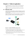
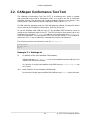
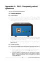
1
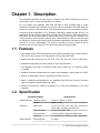
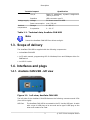
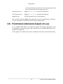
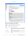
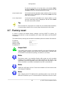
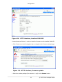
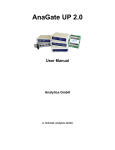
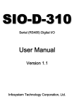
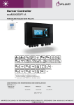
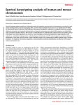
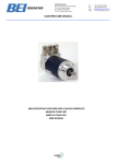
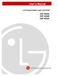
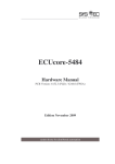
AnaGate CAN USB
User Manual
Analytica GmbH
J. Gossens, Analytica GmbH
AnaGate CAN USB: User Manual
Analytica GmbH
by J. Gossens
This document was generated with DocBook at 2014-10-31 12:46:37.
PDF-Datei (dtsch.): AnaGate-CAN-USB-1.3.pdf
PDF-Datei (engl.): AnaGate-CAN-USB-1.3-EN.pdf
Publication date 14. August 2013
Copyright © 2007-2014 Analytica GmbH
Abstract
This manual describes the intefaces and modes of operation of a AnaGate CAN USB.
All rights reserved. All the information in this manual was compiled with the greatest of care. However, no warranty
can be given for it.
No parts of this manual or the program are to be reproduced in any way (printing, photocopying, microfilm or any
other process) without written authorisation. Any processing, duplication or distribution by means of any electronic
system is also strictly prohibited.
You are also advised that all the names and brand names of the respective companies mentioned in this documentation
are generally protected by brand, trademark or patent laws.
Analytica GmbH
Vorholzstraße 36
76137 Karlsruhe
Germany
Fon +49 (0) 721-43035-0
Fax +49 (0) 721-43035-20
<[email protected]>
www.analytica-gmbh.de [http://www.analytica-gmbh.de]
www.anagate.de [http://www.anagate.de]
Revision History
Revision
1.0
01.10.2010
JGo
Initial version
Revision
1.1
05.10.2011
ASc
New option Boot with operational mode on web configuration side CAN
settings (FW 1.3.16).
Revision
1.2
14.08.2013
ASc
Description of advanced unit settings on web configuration page
Advanced settings (FW 1.3.19) and the informational Status page.
Revision
1.3
01.04.2014
ASc
Support of CANopen Conformance Test Tool of the CiA.
Table of Contents
Introduction ........................................................................................... vii
1. Description ........................................................................................... 1
1.1. Features ..................................................................................... 1
1.2. Specification ................................................................................ 1
1.3. Scope of delivery ......................................................................... 2
1.4. Interfaces and plugs ..................................................................... 2
2. Configuration ........................................................................................ 4
2.1. Initial installation ......................................................................... 4
2.2. Network settings ........................................................................ 12
2.3. CAN settings .............................................................................. 13
2.4. Advanced settings ...................................................................... 15
2.5. Device status ............................................................................. 15
2.6. Functional extensions based on Lua .............................................. 17
2.7. Factory reset ............................................................................. 19
2.8. Firmware update ........................................................................ 20
3. Fields of application ............................................................................. 23
3.1. Gateway mode ........................................................................... 23
3.2. CANopen Conformance Test Tool .................................................. 24
A. FAQ - Frequently asked questions .......................................................... 25
B. Technical support ................................................................................ 28
Abbreviations .......................................................................................... 29
Bibliography ........................................................................................... 30
iii
© 2007-2014 Analytica GmbH
List of Figures
1.1.
1.2.
2.1.
2.2.
2.3.
2.4.
2.5.
2.6.
2.7.
2.8.
2.9.
3.1.
Left view, AnaGate CAN USB ............................................................... 2
Right view, AnaGate CAN USB ............................................................. 3
HTTP interface, AnaGate CAN USB ...................................................... 12
HTTP interface, network settings ......................................................... 13
HTTP interface, CAN settings .............................................................. 14
HTTP interface, CAN settings .............................................................. 15
HTTP interface, Status ....................................................................... 16
HTTP interface, Lua settings ............................................................... 18
AnaGate CAN USB, Example blinking output ......................................... 20
HTTP interface, AnaGate CAN USB ...................................................... 21
HTTP interface, firmware update ......................................................... 21
AnaGate CAN USB in gateway mode ................................................... 23
iv
© 2007-2014 Analytica GmbH
List of Tables
1.1. Technical data, AnaGate CAN USB ........................................................ 1
1.2. Pin layout, CAN plug ........................................................................... 3
A.1. Using AnaGate hardware with firewall .................................................. 26
v
© 2007-2014 Analytica GmbH
List of Examples
3.1. Settings.ini ....................................................................................... 24
vi
© 2007-2014 Analytica GmbH
Introduction
This document describes the features and objectives of the CAN-USB-Gateway
AnaGate CAN USB.
vii
© 2007-2014 Analytica GmbH
Chapter 1. Description
The AnaGate CAN USB connects a PC to a CAN bus via USB. It basically works as a
CAN master with no own CAN identifier on the bus.
For this reason the AnaGate CAN USB provides a USB interface and a single
electrically isolated CAN interface. On the PC side the AnaGate CAN USB identifies
itself as a network card that allows TCP/IP based access to the connected CAN bus.
Controlling and configuration of an AnaGate CAN USB is made through TCP/IP. The
application protocol itself is described in detail (see [TCP-2010]). Thus the access to
the device can be programmed via native calls to the TCP/IP socket interface. This
means that any communication partner with a LAN interface is able to communicate
to the device. Accessing the device with the supplied application libraries for Windows
and Linux is much comfortable. The libraries includes the entire range of device
functions and can be used with conventional programming languages.
1.1. Features
• The AnaGate CAN USB can send and receive CAN messages via its CAN interface.
This can be done using a PC that supports TCP sockets and USB.
• Variable CAN bus speed (10, 20, 50, 62.5, 100, 125, 250, 500, 800 or 1000 kbps).
• Software configurable bus termination for the CAN interface.
• The AnaGate CAN USB is powered directly via its USB port, no external supply
is needed.
• Software interface implemented as virtual network adapter, easy access via TCP/IP.
• System is addressed using a proprietary network protocol.
• Static IP address configuration for the AnaGate CAN USB, the virtual PC network
card is configured automatically via DHCP.
• Several simultaneous network connections (5x TCP) are supported on the CAN
interface.
1.2. Specification
Technical aspect
Measurements
CAN bus
USB interface
Specfication
Desktop casing
120mm x 58mm x 32mm
Weight
approx. 125g
Baud rate
10, 20, 50, 62.5, 100, 125, 250, 500, 800 or
1000 kbps, software configuration
CAN controller
1x Microchip MCP 2515
CAN interface
1x ISO 11898-2, galvanic decoupled
Interface
1x DB9 plug incl. CAN_H, CAN_L and GND
Signaling rate
12 Mbps
1
© 2007-2014 Analytica GmbH
Description
Technical aspect
Voltage supply
Ambient
temperature
Specfication
TCP/IP
Static IP addresses, dynamic assignment
(DHCP) to the PC
Interface
USB connector type B
Voltage
5V direct current via USB
Power consumption
max. 500 mA
Storage
0 .. 85 °C
In operation
0 .. 60 °C
Table 1.1. Technical data, AnaGate CAN USB
Note
Protect the AnaGate CAN USB from direct sunlight.
1.3. Scope of delivery
The AnaGate CAN USB is supplied with the following components:
• 1x AnaGate CAN USB
• 1x CD with manual, programming API for Windows/Linux and CANopen driver for
CANFestival
• 1x USB 2.0 cable
1.4. Interfaces and plugs
1.4.1. AnaGate CAN USB - left view
Figure 1.1. Left view, AnaGate CAN USB
The left side of the AnaGate CAN USB features the following connectors and LEDs
(from left to right):
USB Port
The AnaGate CAN USB is connected to the PC via this USB port. A cable
with a type A USB plug at its one end and a type B USB plug at the
other end needs to be used.
2
© 2007-2014 Analytica GmbH
Description
Busy LED
This yellow LED lights up when the AnaGate CAN USB is processing
incoming CAN messages.
Power LED
This green LED lights up when voltage is being supplied via the USB
port.
Reset
The AnaGate CAN USB can be reset to the factory settings using this
button (see Section 2.7, “ Factory reset” for further details).
1.4.2. AnaGate CAN USB - right view
Figure 1.2. Right view, AnaGate CAN USB
The right side of the AnaGate CAN USB features the following connectors and LEDs
(from left to right):
CAN port
9 pin D-sub connector to connect the CAN bus (CiA recommondation
DS 102).
The pin allocation of the plug can be inferred from the following
table.
Pin
Description
3
GND
2
CAN_L
1,4-6,8,9 not connected
7
CAN_H
Table 1.2. Pin layout, CAN plug
Activity LED
This green LED lights up on activity on the CAN line.
3
© 2007-2014 Analytica GmbH
Chapter 2. Configuration
2.1. Initial installation
First the AnaGate CAN USB must be connected to the PC via USB.
If the PC shows a notification that no device driver could be installed then please
proceed as follows:
2.1.1. Microsoft Windows XP
1.
If you use Microsoft Windows XP then the Found New Hardware Wizard opens
when you first connect the AnaGate CAN USB to your PC.
2.
If the Found New Hardware Wizard doesn't start automatically then you can
also launch it manually:
a.
Firstly, right-click the My Computer symbol, then click Properties.
b.
In the System Properties window switch to the Hardware tab and click
the Device manager button.
c.
Right click the RNDIS/Ethernet Gadget entry that is marked with a yellow
exclamation mark symbol and select Update Driver Software.
3.
In the appearing wizard you first select No, not this time and then click Next.
4.
Click Install from a list or specific location (Advanced), and then click Next.
4
© 2007-2014 Analytica GmbH
Configuration
5.
Click Search for the best driver in these locations and select the Include
this location in the search checkbox. Insert the driver CD-ROM and select the
driver file at \drivers\AnaGateUSB\XP\linux.inf on the CD-ROM by clicking
the Browse button. Then click the Next button.
6.
Confirm the Windows Logo warning with Continue Anyway.
7.
The driver software installation finishes after a short waiting time.
5
© 2007-2014 Analytica GmbH
Configuration
2.1.2. Microsoft Windows 7 und Windows 8/8.1
1.
If you use Microsoft Windows 7 and Windows 8, then open the Control Panel via
the Start menu.
2.
Switch the display mode in the upper right corner to small symbols.
6
© 2007-2014 Analytica GmbH
Configuration
3.
Right click the Device Manager and launch it with administrator priviledges.
Enter your administrator password if prompted by the User Account Control.
4.
Right click the entry RNDIS/Ethernet Gadget below Other Devices that
is marked with a yellow exclamation mark symbol and select Update Driver
Software.
7
© 2007-2014 Analytica GmbH
Configuration
5.
In the appearing assistant you first select Browse my computer for driver
software.
6.
Then click Let me pick from a list of device drivers on my computer.
8
© 2007-2014 Analytica GmbH
Configuration
7.
In the list of device types, choose Network adapters and click the Next button.
8.
Firstly select Microsoft Corporation in the manufacturer list on the left and
then Remote NDIS Compatible Device on the right.
9
© 2007-2014 Analytica GmbH
Configuration
9.
Click Next and confirm the warning with Yes.
10. The driver software installation finishes after a short waiting time.
10
© 2007-2014 Analytica GmbH
Configuration
2.1.3. Factory settings
The AnaGate CAN USB is delivered with the following initial network settings:
IP address
Address type
Network mask
IP address PC
192.168.2.1
static
255.255.255.0
192.168.2.2
The device can now be configured using a standard browser (Internet Explorer,
Firefox, etc.) by using http://192.168.2.1.
11
© 2007-2014 Analytica GmbH
Configuration
Figure 2.1. HTTP interface, AnaGate CAN USB
2.2. Network settings
On the page IP Settings the following settings can be changed.
Device IP address
The IP address of the AnaGate CAN USB is entered in dot
format (e.g. 192.168.1.200).
PC IP address
This IP address in dot format (e.g. 192.168.1.201) is used
by the PC. This IP address must be in the same subnet as the
AnaGate CAN USB address.
USB Subnet mask
The subnet mask
255.255.255.0).
12
is
entered
in
dot
format
(e.g.
© 2007-2014 Analytica GmbH
Configuration
Figure 2.2. HTTP interface, network settings
The inputs will be taken over immediately after clicking the button Save settings
and saved permanently on the AnaGate CAN USB. A restart of the device is not
necessary for activation of the settings.
Note
Maybe the ARP cache of the PC has to be deleted to find the device with
the changed IP address.
Note
After changing the PC IP address the operating system may use the old
address for another up to 15 minutes before it switches to the new value.
If the change must be used immediately then temporarily disconnect the
AnaGate CAN USB from the PC to enforce an update of the used address.
2.3. CAN settings
On the page CAN Settings the global settings for the CAN interface are displayed
and can be changed individually.
13
© 2007-2014 Analytica GmbH
Configuration
Figure 2.3. HTTP interface, CAN settings
Baudrate
The baud rate can be selected easily via a list box
containing all supported values.
Termination
Use the check box to switch on/off the internal
termination resistor.
High Speed
Activates/deactivates the Highspeed mode. In this
operating mode all incoming/outgoing CAN telegrams
are not longer confirmed by the opposite LAN side to
accelerate process throughput. Software-Filters are
switched off too in this mode.
Boot with operational mode
Initial operating mode of the CAN controller. Default
value is offline.
offline
The CAN controller is not active on the
CAN bus (offline).
normal
Normal operating mode. The default
setting of CAN baud rate is used.
listen
In listen mode the CAN
passive. CAN messages are
no messages can be sent
error). The default setting
rate is used.
loopback
In loopback mode every sent CAN
message is mirrowed back by the CAN
controller (no ACK, no errors). The default
setting of CAN baud rate is used.
14
controller is
received, but
(no ACK, no
of CAN baud
© 2007-2014 Analytica GmbH
Configuration
A more detailed description of the operating modes
can be found in the data sheet of the CAN controller
(Microchip MCP2515).
The inputs will be taken over immediately after clicking the button Save settings
and saved permanently on the AnaGate CAN USB. A restart of the device is not
necessary for activation of the settings.
2.4. Advanced settings
On the page CAN Settings the advanced settings of the unit are displayed and can
be changed individually.
Figure 2.4. HTTP interface, CAN settings
Reception timer interval
This value specifies the frequency which is used
to examine if new CAN telegrams are available in
the internal driver buffer. The more frequently this
examination is done, the shorter is the latency of
the re-transmission of the CAN data via ethernet. On
the other hand, its maximum message throughput is
decreased.
The interval is defined in micro seconds, default value
is 3000. To give control immediately to the firmware
after a CAN telegram is received by the CAN driver,
the value 0 has to be set.
The inputs will be taken over immediately after clicking the button Save settings
and saved permanently on the AnaGate CAN USB. A restart of the device is not
necessary for activation of the settings.
2.5. Device status
On the page Status the device dependand status information is shown.
15
© 2007-2014 Analytica GmbH
Configuration
Figure 2.5. HTTP interface, Status
TCP Receive
Number of via TCP/UDP received CAN messages (CAN
firmware)
TCP Transmit
Number of via TCP/UDP transmitted CAN messages (CAN
firmware)
CAN Receive
Number of received CAN messages (CAN bus, CAN driver)
CAN Transmit
Number of transmitted CAN messages (CAN bus, CAN driver)
CAN Discard
• Timeout sending CAN telegram (1s)
This indicates that no active partner is connected to the
CAN bus (no ACK received). Also a wrong baud rate or
missing termination can cause this error.
• A CAN telegram received from CAN bus is discared because
the receive buffer is full (600 entries)
This happens when the CAN firmware does not read
telgrams fast enough out of the driver receive buffer. This
may be the case even if CAN telegrams routed via TCP/UPD
can not received fast enough by the connected ethernet
client(PC,PLC) because of load problems (e.g. full receive
TCP buffers).
• The firmware discards outgoing CAN telegrams because
the send buffer is running full (1000 entries)
This happens when CAN telegrams are not sent fast enough
successfully to CAN bus. This may be a resultant problem
16
© 2007-2014 Analytica GmbH
Configuration
of timeouts during transmission or of overloading the CAN
bus concerning the current used baud rate.
CAN Receive Error
Register Rx-Err-Count of the CAN-Transceiver
CAN Transmit Error
Register Tx-Err-Count of the CAN-Transceiver
Network Error
TCP/UPD transmit error (CAN firmware)
After clicking the button Clear all saved diagnosis entries are deleted on the device.
To reset the system counters the device must be switched off.
2.6. Functional extensions based on Lua
On an AnaGate CAN USB it is possible to execute self-created applications with
an installed Lua script interpreter (see [Prog-2013] for a detailed description of all
programming features).
On the page Lua Lua script files can be uploaded to the device and executed locally.
17
© 2007-2014 Analytica GmbH
Configuration
Figure 2.6. HTTP interface, Lua settings
Browse...
Opens a file upload dialog to select a Lua script file.
Upload
Uploads the selected script file to the device.
Clear
Clears the current script file selection.
Boot script
Script file executed on system startup. Via the button Delete
the boot script can be deactivated. Only one boot script is
allowed.
Running script
Displays the currently executing script file. Via the button
Stop the execution can be cancelled.
Available scripts
Displays all scripts which are currently available on the
device.
18
© 2007-2014 Analytica GmbH
Configuration
To start the execution of a script click on the button Start.
Via button Delete a script can be deleted on the device and
via Boot a script can be defined as boot script.
script output area
In this text area the standard output (stdout) of the currently
executing script is displayed. Via the button Clear this text
area can be cleared.
error output area
In this text area the standard error output (stderr) of the
currently executing script is displayed. Via the button Clear
this text area can be cleared.
Tip
The text areas for script and error output are not refreshed automatically.
A manual page reload of the current page refreshes both text areas.
2.7. Factory reset
In order to restore the default factory settings, hold the RESET for approx. 10
seconds. If the device is reset successfully, the yellow LED blinks until the RESET
is released.
The default factory settings are activated immediately without a restart of the device:
IP address
Address type
Network mask
IP address PC
192.168.2.1
static
255.255.255.0
192.168.2.2
Important
If the RESET push-button is pressed too briefly, the actual IP address and
network mask is pulsed via the yellow LED (Morse code). A second push
of the RESET terminates the pulsing, the device is not reset.
Note
The factory reset is not possible directly after power on until complete
loading of the operating system and the firmware of the device. This
initialization period is signalled via the yellow busy LED. On power on the
LED is switched on and after initialization the LED is switched off.
Note
Maybe the ARP cache of the PC has to be deleted to find the device with
the changed IP address.
Note
After changing the PC IP address the operating system may use the old
address for another up to 15 minutes before it switches to the new value.
19
© 2007-2014 Analytica GmbH
Configuration
If the change must be used immediately then temporarily disconnect the
AnaGate CAN USB from the PC to enforce an update of the used address.
2.7.1. Examining the network settings
It is possible to check the current network settings directly on the device.
After pressing shortly the RESET button the device starts to pulse out the current
n settings via the yellow activity LED. Pressing again the buttons stops the pulsing
immediately.
The IP address and subnet mask are pulsed out, one after the other. Following pulse
codes are used:
• Digits 1, 2, 3, ...., 9: 1x, 2x, ...9x Flashing (200ms delay between each flash)
• Digit 0: 10x flashing (200ms delay between each flash)
• Dot: 1x very fast flash
Between two single digits a delay of 1 seconds is made, and between the IP address
and subnet mask two fast flashes are pulsed out.
Figure 2.7. AnaGate CAN USB, Example blinking output
2.8. Firmware update
The device firmware of the AnaGate CAN USB is updated via the integrated web
server of the device.
On the home page of the web server the current firmware information is displayed.
20
© 2007-2014 Analytica GmbH
Configuration
Figure 2.8. HTTP interface, AnaGate CAN USB
Proceed please as follows, in order to install the firmware on the AnaGate CAN USB:
• Click Firmware on the left navigation bar to navigate to the Firmware-Upload page.
Figure 2.9. HTTP interface, firmware update
• Select the update package (file extension *.upd) via the Browse button.
21
© 2007-2014 Analytica GmbH
Configuration
• Clicking on the button Upload loads the update file to the device and starts the
update process.
• During the update process several installation messaged are displayed on the
website. If the update is successfully finished, Update done! is displayed.
When the update is finished the browser navigates back to the home page. Check,
if the new firmware version is display here.
Warning
If the firmware could not be flashed correctly on the device, the AnaGate
may not longer ready for operation.
Please visit our web site http://www.anagate.de for further information.
22
© 2007-2014 Analytica GmbH
Chapter 3. Fields of application
If the AnaGate CAN USB is connected to the CAN bus, mind the following facts:
• CAN_L: This line has to be connected to the CAN_Low line of the CAN bus.
• CAN_H: This line has to be connected to the CAN_High line of the CAN bus.
• GND: This line can be connected optionally to GND of the other bus devices.
3.1. Gateway mode
In gateway mode the CAN messages are transferred transparently over TCP/IP
between the CAN network and the PC in both directions. The AnaGate CAN USB uses
no unique CAN ID when sending telegrams, this ID has to be set explicitly for each
transmitted message.
All CAN messages received by the device are transmitted to all active application
programs. It is possible to discard all incoming messages in general or to set
individual software filters to reduce the message traffic to the applications.
Figure 3.1. AnaGate CAN USB in gateway mode
The AnaGate CAN USB can be accessed via the following interfaces:
• The software program CAN Monitor, which is included on the documentation CD,
can be used to monitor a CAN bus or to create single CAN telegrams.
• Application programs which are using the included software API inteface.
• Self-created batch files which are executed via the included Lua interpreter with
integrated AnaGate software API.
23
© 2007-2014 Analytica GmbH
Fields of application
3.2. CANopen Conformance Test Tool
The CANopen Conformance Test Tool (CCT) is a software tool, which is created
and supported by the CAN in Automation (CiA). It is used by the CiA to certificate
CANopen devices. The Windows tool needs a hardware device to get access to the
CAN bus and a manufacturer-specific application library called COTI.dll.
All CAN ethernet gateways and the CAN USB gateway offered by Analytica GmbH
can be used by the CANopen Conformance Test Tool of the CiA.
To use the AnaGate CAN USB with the CCT the AnaGate-COTI extension must be
copied to the installation path of the CCT. The COTI extension files can be find on the
AnaGate CD in the path Tools\COTI. In addition, the configuration file Settings.ini
must be customized. The configuration file must also be placed in the installation
path of the CCT, it can be edited by a standard text editor like Notepad.
The following entries are contained in the file Settings.ini:
[Interface0]
IP=192.168.2.1
Port=0
Example 3.1. Settings.ini
IP
IP-Address of the used AnaGate CAN Gateway.
Default address is 192.168.1.254, this is the standard network address of all
models with Ethernet interface.
For devices of model type AnaGate CAN USB the entry IP=192.168.2.1 has
to be used.
Port
Used CAN Port of the AnaGate CAN Gateway.
For devices of model type AnaGate CAN USB the entry Port=0 has to be used.
24
© 2007-2014 Analytica GmbH
Appendix A. FAQ - Frequently asked
questions
Here is a list of frequently asked questions.
A.1. Common questions
Q:
No USB connection
A:
Please check first the physical connection to the device. Basically the AnaGate
has to be connected to a personal computer either directly or through a USB
hub. To establish the connection a cable with a type A plug at one end and a
type B plug at the other end needs to be used.
The physical interconnection is ok if the green power LED lights up while a USB
cable is plugged in and is connected to a running PC. The green LED keeps
being on until the connection breaks down.
If the power LED is always off then please check the wiring and the power
supply via the PC.
Q:
No network connection
A:
If the power LED indicates a proper USB connection (see previous FAQ) but you
still can't connect to the AnaGate then please try the following:
1.
Check if the AnaGate can be reached via ping. To do so in Windows, open a
command prompt and enter the command ping a.b.c.d", where a.b.c.d
is the device IP address.
2.
In case the AnaGate is unreachable via ping, reset the device to factory
settings. Set up the PC network connection to the AnaGate CAN USB to
obtain an IP address automatically. Check if the AnaGate can be reached
via ping 192.168.2.1.
25
© 2007-2014 Analytica GmbH
FAQ - Frequently
asked questions
3.
If the device can be reached via ping then the next step is to try if you can
open a TCP connection to port 5001. Open a Windows command prompt
and enter telnet a.b.c.d 5001, where a.b.c.d is the device IP address. If
this command fails, check if a firewall runs on your PC.
Q:
Using a firewall
A:
When working with a firewall, the a TCP port has to be opened for
communication with the AnaGate device:
Device
Port number
AnaGate I2C
5000
AnaGate CAN
5001
AnaGate CAN USB
5001
AnaGate CAN uno
5001
AnaGate CAN duo
5001, 5101
AnaGate CAN quattro
5001, 5101, 5201, 5301
AnaGate SPI
5002
AnaGate Renesas
5008
AnaGate Universal Programmer
5000, 5002, 5008
AnaGate UP 2.0
5000, 5002, 5008
AnaGate CAN X1
5001
AnaGate CAN X2
5001, 5101
AnaGate CAN X4
5001, 5101, 5201, 5301
AnaGate CAN X8
5001, 5101, 5201, 5301,
5401, 5501, 5601, 5701
Table A.1. Using AnaGate hardware with firewall
A.2. Questions concerning AnaGate CAN
Q:
What is the value of the termination resistor when the termination option of
the device is activated?
A:
The termination resistor of the AnaGate is driven by a FET transistor. The resistor
itself has 110 Ohm while the internal resistance of the FET is 10 Ohm if the FET
is activated. So the resulting resistance is 120 Ohm, as required by the CAN bus.
Q:
Does Analytica offer a CAN gateway which does not have a galvanically isolated
CAN interface?
A:
Any device that is actively connected to a CAN bus should be galvanically
isolated. Especially when using USB-operated devices (like the AnaGate USB)
it is essential to have a galvanically isolated device because the device is power
supplied by the PC.
Q:
How to directly interconnect two CAN ports!
26
© 2007-2014 Analytica GmbH
FAQ - Frequently
asked questions
A:
If you want to interconnect two AnaGate CAN just via a direkt link CAN cable,
you have to switch on the internal termination on both AnaGate CAN devices.
A CAN bus network must have a termination on each side.
Note
it may work with lower baud rates without termination, but it is
recommended to use a termination.
Q:
Receiving a NAK when sending a CAN telegram.
A:
If no CAN partner is connected to the AnaGate CAN (aka the CAN network),
it is not possible to send CAN telegrams. The AnaGate CAN gets a NAK from
the CAN controller. These NAK errors are sent to the AnaGate client via a data
confirmation telegram.
Warning
If data confirmations are switched off no errors are sent to the
client. The option confirmations for data requests can be set via the
CANSetGlobals function. In High Speed Mode data confirmations are
always disabled.
27
© 2007-2014 Analytica GmbH
Appendix B. Technical support
The AnaGate hardware series, software tools and all existing programming interfaces
are developed and supported by Analytica GmbH. Technical support can be requested
as follows:
Internet
The AnaGate web site [http://www.anagate.de/en/index.html] of Analytica GmbH
contains information and software downloads for AnaGate Library users:
• Product updates featuring bug fixes or new features are available here free of
charge.
E-Mail
If you require technical assistance over the Internet please send an e-mail to
<[email protected]>
To help us provide you with the best possible support please keep the following
information and details at hand when you contact our support team.
• Version number of the used programming tool or AnaGate library
• AnaGate hardware series model and firmware version
• Name and version of the operating system you are using
28
© 2007-2014 Analytica GmbH
Abbreviations
I2C
Inter-Integrated Circuit
SCL
Serial Clock Line
SDA
Serial DAta Line
SPI
Serial Peripheral Interface
CLK
Clock
MISO
Master In Slave Out
SS
Slave Select
MOSI
Master Out Slave In
TRST
Test Reset
SRST
Slave Reset
JTAG
Joint Test Action Group
TDI
Test Data Input
TDO
Test Data Output
TMS
Test Mode Select Input
TCK
Test Clock
DHCP
Dynamic Host Configuration Protocol
29
© 2007-2014 Analytica GmbH
Bibliography
Books
[LuaRef2006-EN] Roberto Ierusalimschy, Luiz Henrique Figueiredo, and Waldemar Celes.
Copyright © 2006 R. Ierusalimschy, L. H. de Figueiredo, W. Celes. ISBN 85-903798-3-3.
Lua.org. Lua 5.1 Reference Manual.
[LuaProg2006-EN] Roberto Ierusalimschy. Copyright © 2006 Roberto Ierusalimschy, Rio de
Janeiro. ISBN 85-903798-2-5. Lua.org. Programming in Lua (second edition).
[LuaProg2013-EN] Roberto Ierusalimschy. Copyright © 2013 Roberto Ierusalimschy, Rio de
Janeiro. ISBN 85-903798-5-X. Lua.org. Programming in Lua, Third Edition.
Other publications
[NXP-I2C] NXP Semiconductors. Copyright © 2007 NXP Semiconductors. UM10204. I2C-bus
specification and user manual. Rev. 03. 19.06.2007.
[TCP-2010] Analytica GmbH. Copyright © 2010 Analytica GmbH.
communication . Version 1.2.6. 15.05.2008.
[Prog-2013] Analytica GmbH. Copyright © 2013 Analytica GmbH.
Programmer's Manual . Version 2.0. 15.05.2013.
Manual TCP-IP
AnaGate API 2 .
[CiA-DS301] Copyright © 2002 CAN in Automation (CiA) e. V.. CAN in Automation (CiA) e.V..
13.02.2002. Cia 301, CANopen Application Layer and Communication Profile.
30
© 2007-2014 Analytica GmbH