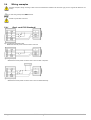
1
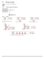
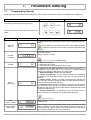
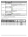
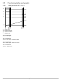
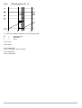
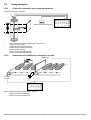
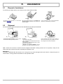
MC235.09
Position control with self-learning
User manual and installation
1. Information
1
2. Description
6
3. Installation
9
4. Electric Properties
10
5. Wiring
12
6. Functioning
18
7. Parameters entering
20
8. Use
24
9. Assistance
30
MUIMC23509_EN10 - 07/10/2015
1. Informations
1.1
1.2
1.3
1.4
1.5
Symbols..............................................................................................................4
Limited Warranty................................................................................................4
Reference Manuals............................................................................................4
Validity................................................................................................................5
Norm references.................................................................................................5
2. Description
2.1
2.2
2.3
4. Electric properties
18
20
Programming (Set-up)........................................................................................20
Calculation of the encoder resolution.................................................................21
Errors caused by not ended resolutions.............................................................22
Relative/absolute counter(C = 1*) .....................................................................22
Preset of the Count ............................................................................................22
With the parameter AI = 1*.................................................................................23
With the parameter C = 2*..................................................................................23
Max and Min Quota Self-Learning......................................................................23
8. Use
8.1
8.2
8.3
12
Release message...............................................................................................18
Keyboard functions.............................................................................................18
Using graphic......................................................................................................19
“Data out of range” visualization ........................................................................19
7. Parameters entering
7.1
7.2
7.3
7.4
7.5
7.6
7.7
7.8
10
Connection description.......................................................................................12
U04: expansion card...........................................................................................13
Wirings examples...............................................................................................14
Wiring examples.................................................................................................15
6. Functioning
6.1
6.2
6.3
6.4
9
Power supply......................................................................................................10
I1 / I2: Digitals inputs.........................................................................................10
PH A /PH B: Bidirectional encoder phases........................................................11
U1/U2/U3/U4: digital outputs (expansion card U04)..........................................11
5. Wiring
5.1
5.2
5.3
5.4
6
Product code.......................................................................................................6
Technical characteristics....................................................................................7
Mechanical dimensions......................................................................................8
3. Installation
4.1
4.2
4.3
4.4
4
24
Working programs and auxiliary functions.........................................................24
Functioning tables and graphis..........................................................................25
Using examples..................................................................................................29
9. Assistance
9.1
9.2
Request of assistance........................................................................................30
Shipment.............................................................................................................30
30
1.
Informations
Thanks for buying this QEM instruments. We'll be glad to receive any suggestion at our e-mail address [email protected].
1.1
Symbols
Not reading the message will be dangerous for the instruments integrity and/or for the
success of the operation.
Note: Important information for the correct use of the instruments.
For more informations see the user manual indicated in the message.
For more informations see the indicated pages.
1.2
Limited Warranty
For two years from the original acquisition, QEM will repair or replace for free controls and devices
that QEM thinks be imperfect in materials or quality. This warranty is not valid if the object has been
tampered by not authorized persons or used in an inappropriate way.
This warranty replaces all other warranties either expressed or implicit.
QEM doesn't hold personally responsible for all charges (installation or uninstalling included), drawback, or damage caused by our products, made or sold. In any case, QEM total duty, always will not
exceed the control total price.
Claims for refunds of selling price, reparations, or replacements must be referred to QEM with all
pertinent data (damage, purchase date, developed work and problem).
It is not provided any duty for batteries and fusible cut-out consumption.
The product must be returned only with a written notification, included the Number of Restitution
Authorization QEM and must be paid all forwarding charges.
1.3
Reference Manuals
The documentation referred to the QEM instrumentation in divided in many issues that allows an
easy utilization.
MUI: User and installation manual
Instrument hardware and software informations.
MIMAT: Maintenance, service and installation manual.
Informations on: wiring, right calibration, parameters insertion and breakdown
individuation.
It is possible to download manuals from www.qem.it
Informations
MUIMC23509_EN10 07/10/2015
4 of 32
1.4
Validity
M: manual
S: instrument
The present document is fully valid excepted mistakes or omissions.
Release
1
Editor:
Description
M
M
M
M
M
M
M
M
M
M
Date
New manual.
Data corrections.
Content review.
English version.
New measure
Insert new code
Insert CX9 model
Input's type note
Change outputs voltage value from 110V to 24V
New function 3 on the A1 parameter
15/12/2005
22/12/2005
31/10/2006
10/11/2006
13/04/2007
03/10/2007
15/12/2010
25/07/2011
12/01/2015
07/10/2015
Product Manager:
Approved by Technical manager:
Trade Marks
The copyright of this user manual is reserved. No one part of this document can be reproduced or
copy without the QEM appointment. QEM doesn't present insurances or warranties on contents
and declines all responsibilities on identity warranties. In this document, informations can be modified without any notice.
QEM doesn't have any responsibility on this document.
Trade Marks:
- QEM® is a trade mark.
1.5
Norm references
European norm includes some rules and raccomandations about control security systems with elements of operator interface.
Protection rate
IP20 (Conform on EN 60-5-29)
Informations
Frontal protection rate for container (optional)
IP54
IP65 frontal protection rate with packing for
container(optional)
IP65
Vibration resistance
Conform on IEC 68-2-6
Bump resistance
Conform on IEC 68-2-27
Jamming immunity
Conform on EN 50082-2
Emission level
Conform on EN 50081-2
Container
DIN43700
MUIMC23509_EN10 07/10/2015
5 of 32
2.
Description
MC235.09 is a quotas and axis position visualizator, has 4 programmable outputs (for quotas and also in the intervention
logic) that can allows to use the instrument also as measurer and position controller respect to the set measures ore selflearned.
This instrument substitutes obsolete products like HB235.09A
General Characteristics
- 2 digital inputs
- 4 digital programmable outputs;
- 1 counter input;
- Preset quota loading;
- Self-learned quotas;
- Single cycle functioning / continuous;
- Polarized terminals.
Options
- Personalized panel;
- Dedicated power supply voltage;
- Superior encoder counter frequencies;
- Specialization on customer specifications..
2.1
Product code
Model
MC235
Characteristics
.
09
/
T001
/
CX2
/
U04
/
Base Card
Firmware Version
Power supply
CX2 (standard)
Keyboard code
T001 = standard
keyboard.
24Vac
Expansion Card
CX_ : Basic Card
PHA / PHB:
Encoder
phases
I1 / I2 *:
Digital
inputs
Vout ext
Frequency
Encoder type
Voltage level of
phases
Frequency
Polarization
CX1 CX2 CX3
15 KHz
PP
encoder
Inputs voltage level
Delivered power supply
CX4
CX5 CX6
200 KHz
NPN
CX8
LD
12 / 24 V
PNP
CX7
CX9 CXA CXB
15KHz
50 KHz
PP
PP
2 / 3,5 V
10 KHz
PNP NPN
PNP
100 KHz
NPN
10,5 / 26,5 V
12 V
5V
12 / 24 V
10KHz
10 KHz
PNP NPN
5V
5V
10,5 / 26,5 V
12 V
* Activation time depending from the A1 parameter (0, 1 and 2 = 50ms; 3 = 2ms)
Description
MUIMC23509_EN10 07/10/2015
6 of 32
2.1.1
Accessories
Description
Measured in mm.
2.2
Code
Container frontal protection (IP54)
23040001
Packing frontal protection for container (IP65)
23040044
Technical characteristics
weight (max. hardware composition)
450
Container material
Plastic noryl UL 94 V-O
Display
1
6
display h = 8
display h = 14
Buttons
4
mechanical buttons with tactile feeling
Led
5
Working temperature
0 / 50
Relative humidity
90%
Altitude
0 / 2000 m
Atmosphere
Not corrosive gasses
Transport and stocking temperature
-25 / +70 °C
Description
gr
°C
without condensation
MUIMC23509_EN10 07/10/2015
7 of 32
2.3
Mechanical dimensions
Measured in mm.
Mechanical installation pag. 9
Fig. 1 Back view
Fig. 2 Perforation area
Description
MUIMC23509_EN10 07/10/2015
8 of 32
3.
Installation
For a correct
installation
read
MIMAT
manual
a) Insert the instrument in the hole;
b) Apply hooks;
c) To fix the instruments screw down.
Installation
MUIMC23509_EN10 07/10/2015
9 of 32
4.
4.1
•
Electric properties
Power supply
= Variable data. See the model Basic Card CX_
Available power supply
Vac
Vdc
24 / 27 / 110 / 230 Vac
24 Vdc
Range val
-15 / +10%
Frequency
50 / 60 Hz
Absorption max.
Volt ext.*
4.2
•
18 / 30 V
dc
8 VA
12 Vdc - 100mA
I1 / I2: Digitals inputs
= Variable data. See the model Basic Card CX_
Polarization *
CX 1
CX 2 (standard)
PNP
NPN
Frequency *
10 Khz
Optoinsulation
1500 V rms
Nominal operating voltage
12 / 24 Vdc
Logic state 0 Voltage
<3 V
Logic state 1 Voltage
>8 V
Input resistance
1,5
KW
Internal voltage drop (see Fig.3)
1,2
V
Lowest acquisition time I1
Activation C
50 ms
Activation I
10
Lowest acquisition I2
msec.
50 ms
C: continuous
I: impulsive
N.B.: For the other inputs' features,
please contact QEM's sales office
Fig. 3 Internal voltage drop
Electric properties
MUIMC23509_EN10 07/10/2015
10 of 32
4.3
PH A /PH B: Bidirectional encoder phases
* = Variable data. See the model Basic Card CX_
Encoder 12 V
Polarization *
Encoder 24 V
CX 1
CX 2 (standard)
PNP
NPN / Push - Pull
Frequency *
20 Khz
Optoinsulation
1500 Vrms
Logic state 0 Voltage
<3
Volt
Logic state 1 Voltage
>8
Volt
Input resistance
1,5
KW
Internal voltage drop
1,2 Volt
4.4
N.B.: For the other inputs' features,
please contact QEM's sales office.
U1/U2/U3/U4: digital outputs (expansion card U04)
Commutable load
AC – DC (NPN/PNP)
Optoinsulation
1500 Vrms
Functioning Voltage
24 Vac/Vdc
Maximum current
70 mA
Dispersion current
20 mA
Internal voltage falling
2,5 V
Commutation time from ON to OFF
120 ms
Commutation time from OFF to ON
8 ms
Electric properties
MUIMC23509_EN10 07/10/2015
11 of 32
5.
5.1
Wiring
Connection description
10
11
12
13 14
1
2
3
4
5
6
7
8
9
* = Variable data. See the model Basic Card CX
For more information on l1 input programming, see Function l1 input in Program (set-up) at pag 21
Way of activation
Logic activation state
Name
Terminal
Fig. 4 Back connector
Description
1
12 V *
2
0V
3
I1
On
4
I2
On
C
Digital input I2.
Zero setting counter, or charging permission.
5
PH A
6
PH B
On
I
Bidirectional encoder phases.
7
Vac / - Vdc
8
Vac / + Vdc
9
GND
-
Volt ext.
C / I Digital input I1 / Phase Zero encoder. Programmable.
-
Power supply voltage.
-
Ground connection.
Connect a conductor with 2mm2 section to the PE bar.
C: continuous
I: impulsive
Wiring
MUIMC23509_EN10 07/10/2015
12 of 32
5.2
U04: expansion card
10
11
12
13 14
1
2
3
4
5
6
7
8
9
for more information for the programming, please see at the chapter Programming (Set-up) at pag. 20
For more information see the chapter Use at pag. 24
Name
Logic activation state
10
COM
ON
-
Common digital outputs (U1÷U4)
11
U1
ON
C
Min Quota. Programmable by "E" parameter.
12
U2
ON
C
Min slow-down. It reduces the axis speed near the arrival point.. Programmable by
"E" parameter.
13
U3
ON
C
Max Slow-down. It reduces the axis speed near the arrival point. Programmable by
“E” parameter.
14
U4
ON
P
Max quota. Programmable by "E" parameter.
Way of activation
Terminal
Fig. 5 Expansion terminal U04
Description
Legend
C: continuous
P= Programmable
Wiring
MUIMC23509_EN10 07/10/2015
13 of 32
5.3
Wirings examples
For a correct installation see MIMAT manual.
5.3.1
5.3.1.1
Power supply connections
Notes
Fig. 6 Use a transformer 50VA min.
sec. 24 Volt
Fig. 9 Don't use auto transformer
Fig. 7 Don't connect power supply
voltage to the ground
Fig. 8 Don't connect the transformer
central terminal to the ground
Fig. 10 Don't use transformer headed by an autotransformer
Fig. 11 Don't set coils, electro-valve etc. in parallel
Wiring
MUIMC23509_EN10 07/10/2015
14 of 32
5.4
Wiring examples
The wiring examples change according to Basic Card CX characteristics installed in the instrument. (pag. Errore: sorgente del riferimento non
trovata)
For other wiring example read MIMAT manual.
Possible only with Basic Card CX2.
5.4.1
Basic card CX2 (Standard)
Fig. 12 Digital input polarization NPN.
Bidirectional encoder phases connection NPN / Push Pull.
Fig. 13 Digital input polarization NPN.
Bidirectional encoder phases connection NPN / Push Pull with I1 Impulsive.
Fig. 14 Digital input polarization NPN.
Bidirectional encoder phases connection NPN / Push Pull feeded externally
Wiring
MUIMC23509_EN10 07/10/2015
15 of 32
Fig. 15 Bidirectional encoder phases connection NPN / Push Pull with 2 proximity like encoder.
Fig. 16 Digital inputs NPN connected to a PLC feeded by a MC235.09.
Fig. 17 Digital inputs NPN connected and feeded (Vdc) by a PLCI
Wiring
MUIMC23509_EN10 07/10/2015
16 of 32
5.4.2
Basic Card CX1
Fig. 18 Digital input polarization PNP.
Bidirectional encoder phases connection PNP
Fig. 19 Digital inputs PNP connected to a PLC and feeded by a MC235.09.
Fig. 20 Digital inputs PNP connected and feeded (Vdc) by a PLC
5.4.3
Expansion card U04
Fig. 21 Output expansion (U04)
Wiring
MUIMC23509_EN10 07/10/2015
17 of 32
6.
6.1
Functioning
Release message
At the turning on the display shows:
1°: a) Instrument family;
b) Instrument firmware version.
6.2
2°: c) Release;
b) Granting.
Keyboard functions
Some buttons functioning depends by the Programmation (Set-up) pag. 20.
Fig. 22 Keyboard
Data insertions: It confirms the data introduction.
Normal functioning: pushing the button enter the quota min and max programming.
Enter
Clear
Data insertions: Cancel the inserted value, giving the past value.
Normal working: If C = 1 counter reset;
If C = 2, allows / not allows relative counter.
It increases the selected number.
It selects the number with a shift from left to right.
Led. ON = gives the parameters introduction state (set-up).
Led. ON = informs the access to the storage register “PRS”.
Led. Switched on during the min and max quota insertion.
a) Led. Lighting after a self-learning.
b) Display (first display from left) gives a differentiation of visualized data.
If A = 1 informs negative counter.
+
Functioning
Access to password protected functions
MUIMC23509_EN10 07/10/2015
18 of 32
6.3
*
Using graphic
= Programmation (Set-up) parameter pag. 20
++
Led = Off.
Led = On.
6.4
“Data out of range” visualization
If introduced data are out of range, the display visualizes:
a) Data out of range
Functioning
MUIMC23509_EN10 07/10/2015
19 of 32
7.
7.1
Parameters entering
Programming (Set-up)
Parameters define the instrument functioning way, their access is reserved for a technical installation with a password.
Description
Keyboard
Visualization
For entering in the Programming (Set-up).
+
x 3 sec.
Introduce the access code “235” and confirm with
enter.
Function
H... 0
H 235
Display
Description
It specifys the number of decimals for the counter visualization (axis position).
decimals
Max. 3
Encoder
resolution
P
0
The introduction of decimals influences on the VISUALIZATION;
the precision depends on the number of impulses provided by the
encoder.
ENCODER ROTATION-IMPULSES MOLTIPLICATOR to allow different unit of measure.
Range: 0.00200 / 4.00000
L100000
For more info please see the MIMAT manual.
CLEAR
Way of
functioning
C
E
0 = blocked functioning;
1 = Set to zero the counter;
2 = Load the memory register PRS on the counter.
0
0 = Blocks for the data insertion (CLEAR remains activated). It is
possible the self learning by I1 and I2 inputs if enabled. Pushing
ENTER it is possible to read the min and max quota.
1 = Keyboard enabled. Remains the self-learning.
2 = Double pre-selection. The min quota becomes an intermediate
pre-selection with slow-down between zero and max quota (with selflearning).
3 = Block counter. Similar to Double pre-selection but reached the
max quota the counter is blocked and the U4 output remains excited up
to the next reset (without self-learning).
4 = Automatic Cycle. Similar to Double pre-selection but reached the
max, at the end of the set time, the value of the max quota will be sub tracted form the count and the U4 output remains excited for the the set
time(without self-learning).
5 = Single pre-selection. It is enabled only the max quota. His functioning is similar to the automatic cycle (without self-learning).
0
See tables at pag. 25
Timer
0,001 ÷ 9,999
Min Slow-down
Max. 9999
Parameters entering
t
UL
9000
9999
Timer that starts when the U4 output is excited and it determinates the
excitation time.
Tell the distance form the positioning quota, where the axis has to slowdown to facilitate the stop. Where the speed changes is the result of:
Positioning quota – Min slow-down. The introduction of too small values
can change the precision in the in the positioning.
MUIMC23509_EN10 07/10/2015
20 of 32
Function
Max slow-down
Max. 9999
Display
FL
Description
Tell the distance form the positioning quota, where the axis has to slowdown to facilitate the stop. Where the speed changes is the result of:
Positioning quota – Min slow-down. The introduction of too small values
can change the precision in the in the positioning..
9999
0 = Continuous loading of the memory register PRS on the counter.
1 = Impulsive loading of the memory register PRS on the counter.
2 = Min quota self-learning.
3 = Similar of the 1 mode but the minimum activation time is 2ms instead of 50ms.
Input I2
functioning
AI
0
With the C= 2 parameter, the A1 parameter is forced to 2.
With E = 3,4,5 the A1
Input I1
A2
parameter cannot be “2”.
0 =Min quota self-learning.
1 =Max quota self-learning.
2 =Disabled input.
0
With E = 3,4,5 the A2 parameter is 2.
Memory register
PRS
123456
Loaded quota on the counter at the activation of the I2 input, if the
A1¹2 or pushing the CLEAR button if C=2.
Ended the programming of the last function, returns the first visualization, before entering in the set-up.
7.2
Calculation of the encoder resolution
L
In “Encoder resolution” ( ) parameter is the number of unite measure that we want visualize in the number of impulses
generated for an encoder phase.
Example:
Space in
measure unit
Encoder
Impulses
Encoder
resolution
S
I
L=S/I
500
2000
500
P
Visualization
(conversion of impulses)
0,25000
0
2000
0,25000
1
7423
4096
1,81226
1
5000
2000
2,50000
2
500
50 0
742 3
50 00
Parameters entering
MUIMC23509_EN10 07/10/2015
21 of 32
7.3
Errors caused by not ended resolutions
L
In the “Encoder resolution” ( ) parameter, at page 20, it is possible to specify the value of the coefficient to convert im pulses in measure unit with a precision up to 5 decimals.
If the coefficient has a number of decimals bigger of five it is needed an insertion of an approximate value. In this way an
imprecision occurs.
See an example for this kind of imprecision and when can give problems.
If the space in 0.1 mm is :
S = 7423
And to this space correspond a number of impulses:
I = 4096
The theoric resolution is:
L = 1.812255859...
That has to be approximated to the value:
L = 1.81226
In this way every 4096 impulses we have an imprecision of 5 x 10⁻⁶ decim of mm.
The results is that after:
4096 / (5 x 10⁻⁶ ) = 8192 x 108 impulses
The visualization of the measure is not correct, is failed of a decim of millimetres.
The user has to decide if for his application this imprecision is tolerable.
It is possible that:
- The number of impulses to commit an error of a decim of millimeter is very big and in the application it'll never be
reached without a counter reset, so there are no problems.
- The number of impulses can be reached, but the imprecision a decim of millimeter is irrilevant in the application, so there
are no problems.
- The max number of impulses reached during the application, without having a counter reset, is many times more than
the calculated value.
So the error is also bigger than a decim of millimeter , that it is not acceptable. In this case we suggest to do mechanical
modifications or to the number of impulses of the transducer to allow a resolution ended in max 5 decimals.
7.4
Relative/absolute counter(C = 1*)
* = Program (Set-up)parameter pag. 20
7.5
Preset of the Count
for more information , please see at the chapter Programming (Using graphic) at pag. 19
* = Parameter of Set-up pag. 20
The encoder can be moved without the instrument power-supply lit is necessary that at every power on an instrument recalibration with a physic measure in the axis; this function, generally named “Preset”, can be obtained using incremental
transducers with “zero impulse” or with limit switches.
7.5.1
With the parameter AI = 0*
Activating the I2 digital input, it transfers the value of the PRS register to the count.
The count is blocked to the PRS value until the inputs remains enabled.
46046
Memory
I2
PRS register
046046
Parameters entering
MUIMC23509_EN10 07/10/2015
22 of 32
7.6
With the parameter AI = 1*
The activation of the digital input I2 transfers the value from the PRS register to the count. The count is not blocked.
46046
Memory
I2
PRS register
046046
7.7
With the parameter C = 2*
Pushing CLEAR the value of the PRS value is transferred in the count.
Memory
PRS register
46046
7.8
046046
Max and Min Quota Self-Learning
The instrument doesn't self-learn the min quota if bigger than the max and contrary.
With the parameter E = 3,4,5 the self-learning is disabled.
7.8.1
Minimum quota self-learning
A1 = 2
Memory
Minimum
quota (U)
I2
1234
1234
I2 has to be enabled at least for 50 milliseconds.
A2 = 0
Memory
Minimum
quota (U)
I1
1234
1234
I1 has to be enabled at least for 30 milliseconds.
7.8.2
Maximum quota self-learning
A2 = 1
Memory
Maximum
quota(F)
I1
5678
5678
I1 has to be enabled at least for 30 milliseconds.
Parameters entering
MUIMC23509_EN10 07/10/2015
23 of 32
8.
8.1
8.1.1
Use
Working programs and auxiliary functions
Max and Min quota inserting
Description
Buttons
Enter to insertion of max and min quotas.
Is visualized the min quota in use (lighting).
The operator can insert the desired quota and confirm it
with ENTER.
X 2 sec.
Display
U123456
= on
It is required the inserting of the max quota.
The operator can insert the desired quota and confirm it
with ENTER.
The display returns on the count visualization.
F123456
= on
If in set-up "E" = 5 the display visualizes only the max quota.
= off
8.1.2
Visualizations
The instrument visualizes also the negative quotas, but the intermediate ones, max and preset can be only positive.
t
During the automatic zero setting the parameter timer ( ) has to be smaller than the time necessary to the machine reach the pre-selection.
Example.
Count Frequency
= 300 impulses / sec
Quota
= 450 impulses
Timer (t)
= 2 seconds (wrong)
the timer has to be smaller than 1.5 seconds for not cause malfunctions.
Use
MUIMC23509_EN10 07/10/2015
24 of 32
8.2
8.2.1
Functioning tables and graphis
With parameter "E" = 0 or 1
U1
U2
U3
U4
Count
U = Min quota
UL = Min slow-down
FL = Max slow-down
F = Max quota
U1 is excited with:
Count £ Min quota
U2 is excited with:
Count £ Min quota + Min slow-down
U3 is excited with:
Cont ³ Max quota – Max slow-down
U4 is excited with:
Count ³ Max quota
Use
MUIMC23509_EN10 07/10/2015
25 of 32
8.2.2
With parameter "E" = 2 or 3
U1
U2
U3
U4
Count
U = Min quota
UL = Min slow down
FL = Max slow down
F = Max quota
U1 is excited with:
Count ³ Min quota
U2 is excited with:
Count ³ Min quota - Min slow down
U3 is excited with:
Count ³ Max quota - Max slow down
U4 is excited with:
Count ³ Max quota
When
Use
F quota is reached the counter will be blocked and U4 output remain enabled up to the next counter reset.
MUIMC23509_EN10 07/10/2015
26 of 32
8.2.3
With parameter "E" = 4
U1
U2
U3
U4
Count
x = results of the difference between count and quota.
U
UL
FL
F
t
= Min quota
= Min slow down
= Max slow down
= Max quota
= Timer
U1 is excited with:
Count ³ Min quota
U2 is excited with:
Count ³ Min quota - Min slow down
U3 is excited with:
Count ³ Max quota - Max slow down
U4 is excited with:
Count ³ Max quota
Use
MUIMC23509_EN10 07/10/2015
27 of 32
8.2.4
With parameter "E" = 5
x = result of the difference between the cont and the quota.
FL
F
t
=
=
=
Max slow down
Max quota
Timer
U1 not used
U2 not used
U3 is excited with:
Count ³ Max quota - Max slow down
U4 is excited with:
Count ³ Max quota
Use
MUIMC23509_EN10 07/10/2015
28 of 32
8.3
Using examples
8.3.1
Control for automatic spray painting machines
Encoder in the motor traslations
Buttons for the self-learning
-
Ways of functioning (set up parameter E set to 0 or 1)
Output U1 (min quota)
Output U2 (min quota slow-down)
Output U3 (max quota slow-down)
Output U4 (max quota)
Input I1 (max quota self-learning)
Input I2 (min quota self-learning)
8.3.2
Separation and outdistance of material on a belt
Obstruction
Encoder
counter
Motor
Ways of functioning (set-up parameter E set to 4)
Output U1 (lift the obstruction)
Output U4 (low the obstruction)
Use
MUIMC23509_EN10 07/10/2015
29 of 32
9.
9.1
Assistance
Request of assistance
To provide you a faster service, at a minimum cost, we do need your help.
a)
a) Follow all the information in the manual
MIMAT (www.qem.it)
9.2
b)
b) If the problem persists, fill the Module for
technical service attached to this manual and
send it to QEM.
c)
c) Our technicians will get the fundamentals
elements to understand your problem.
Shipment
We recommend to pack the instrument with materials that can damp eventual falls.
a)
a) Use the original package: it has to protect
the instrument during the transportation.
b)
b) Attach:
- An anomaly description;
- Part of the electrical sketch where the instrument is inserted
- Programming of the instrument (set up, working quotes, parameters..).
- Request of a repairing estimate; if not requested the cost will be calculated at the end.
c)
c) An exhaustive description of the problem allows to find and solve your problem. An accurate package avoids further drawbacks.
QEM informs the courteous costumer that the shipped instruments unfairly packed won't be repaired, except for the
cases where the costumer assumes completely the reparation cost.
Motivations
The QEM established like that because a too strong line may cause damages that could reveal in a temporal space of
some months, causing doubts and shadows on the reparation done.
Assistance
MUIMC23509_EN10 07/10/2015
30 of 32
Modulo per Assistenza Tecnica
Module for Technical Service
Ditta /
Firm :...............................................................
Rif.:.............................................................................
Indirizzo / Address:............................................................................................................................................
...........................................................................................................................................................................
Tel..........................................................................
....
Fax..............................................................................
E – mail..............................................................................................................................................................
Codice strumento / Instrument Code :...........................................................................................................
Alimentazione strumento / Power Supply: ........................................................................................................
Tipo di macchina / Machine type:
...........................................................................................................................................................................
...........................................................................................................................................................................
...........................................................................................................................................................................
...........................................................................................................................................................................
...........................................................................................................................................................................
...........................................................................................................................................................................
Descrizione ciclo macchina / Cycle machine description:
...........................................................................................................................................................................
...........................................................................................................................................................................
...........................................................................................................................................................................
...........................................................................................................................................................................
...........................................................................................................................................................................
Parametri / Parameters:
...........................................................................................................................................................................
...........................................................................................................................................................................
...........................................................................................................................................................................
...........................................................................................................................................................................
...........................................................................................................................................................................
...........................................................................................................................................................................
...........................................................................................................................................................................
...........................................................................................................................................................................
...........................................................................................................................................................................
...........................................................................................................................................................................
Descrizione anomalia / Anomaly Description:
...........................................................................................................................................................................
...........................................................................................................................................................................
...........................................................................................................................................................................
...........................................................................................................................................................................
...........................................................................................................................................................................
Frequenza anomalia / Anomaly frequency :
Assistance
Continuo / Continuous
Saltuario / Irregular
Dopo un certo tempo / After a few time
All'accensione / At the switching on
Allo spegnimento / At the switching off
Altro / Other: ..........................................................
....................................................................................
....................................................................................
....................................................................................
....................................................................................
....................................................................................
MUIMC23509_EN10 07/10/2015
31 of 32
QEM S.r.l.
S.S. 11 Signolo n. 36,
36054 Montebello Vic. No
Vicenza – ITALY
Tel. +39 0444 440061
Fax + 39 0444 440229
http:\\www.qem.it
e-mail: [email protected]
The CE mark of the instrument doesn't release the installer from the acknowledgement and
the accomplishment of the prescriptive reference obligation of his product.
Assistance
MUIMC23509_EN10 07/10/2015
32 of 32