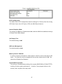
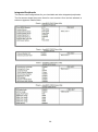
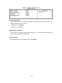
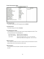
1
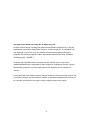
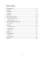
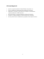
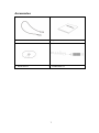
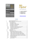
SI-28 Series User Manual 2011 November V1 Copyright © 2011 IBASE Technology INC. All Rights Reserved. No part of this manual, including the products and software described in it, may be reproduced, transmitted, transcribed, stored in a retrieval system, or translated into any language in any form or by any means, except documentation kept by the purchaser for backup purposes, without the express written permission of IBASE Technology INC. (“IBASE”). Products and corporate names mentioned in this manual may or may not be registered trademarks or copyrights of their respective companies, and are used for identification purposes only. All trademarks are the property of their respective owners. Every effort has been made to ensure that the contents of this manual are correct and up to date. However, the manufacturer makes no guarantee regarding the accuracy of its contents, and reserves the right to make changes without prior notice. 2 Table of Contents Acknowledgments................................................................................................. 6 Accessories ........................................................................................................... 7 Components.......................................................................................................... 8 I/O View ...................................................................................................................... 8 Specification ........................................................................................................10 Mounting SI-28 to the Wall ..................................................................................11 Wall mounting requirements ...................................................................................... 11 Selecting the location ................................................................................................. 12 Exploded view of the SI-28 assembly ....................................................................13 Parts description ........................................................................................................ 13 Installation ..........................................................................................................14 Installing the memory ................................................................................................ 14 Installing the CPU ....................................................................................................... 15 Setting Jumper ........................................................................................................... 16 BIOS Setup ...........................................................................................................18 BIOS Introduction ....................................................................................................... 18 BIOS Setup ................................................................................................................. 18 Driver Installation ................................................................................................36 Appendix .............................................................................................................44 3 Safety Information Your SI-28 is designed and tested to meet the latest standards of safety for information technology equipment. However, to ensure your safety, it is important that you read the following safety instructions. Setting up your system Read and follow all instructions in the documentation before you operate your system. Do not use this product near water. Set up the system on a stable surface or secure on wall with the provided rail. Do not secure the system on any unstable plane or without the rail. Do not place this product on an unstable cart, stand, or table. The product may fall, causing serious damage to the product. Slots and openings on the chassis are for ventilation. Do not block or cover these openings. Make sure you leave plenty of space around the system for ventilation. Never insert objects of any kind into the ventilation openings. This system should be operated from the type of power indicated on the marking label. If you are not sure of the type of power available, consult your dealer or local power company. Use this product in environments with ambient temperatures between 0˚C and 45˚C. If you use an extension cord, make sure that the total ampere rating of the devices plugged into the extension cord does not exceed its ampere rating. Care during use Do not walk on the power cord or allow anything to rest on it. Do not spill water or any other liquids on your system. When the system is turned off, a small amount of electrical current still flows. Always unplug all power, and network cables from the power outlets before cleaning the system. If you encounter the following technical problems with the product, unplug the power cord and contact a qualified service technician or your retailer. The power cord or plug is damaged. Liquid has been spilled into the system. The system does not function properly even if you follow the operating instructions. The system was dropped or the cabinet is damaged. 4 CAUTION: Danger of explosion if battery is incorrectly replaced. Replace only with the same or equivalent type recommended by the manufacturer. Dispose of used batteries according to the manufacturer’s instructions. The warranty does not apply to the products that have been disassembled by users 5 Acknowledgments Award is a registered trademark of Award Software International, Inc. PS/2 is a trademark of International Business Machines Corporation. AMD Athlon™ 64 / Athlon™ 64 x2 (dual core) / Sempron™ processors are registered trademarks of AMD Corporation. Microsoft Windows is a registered trademark of Microsoft Corporation. Winbond is a registered trademark of Winbond Electronics Corporation. All other product names or trademarks are properties of their respective owners. 6 Accessories a. Power Cord x 1 b. System Manual x 1 c. Driver CD x 1 d. Power Brick x 1 7 Components I/O View Refer to the diagram below to identify the components on this side of the system. The power switch allows powering ON and OFF the system. HDD The hard disk LED blinks when data is being written into or read from the hard disk drive. PWR The power LED illuminated when system been power on. HDMI (E4690 / HD3200) The HDMI (High Definition Multimedia Interface) is a compact audio/video (connector 4 exclusive) interface to transmitting uncompressed digital data come from HD3200 or E4690 (discrete graphic chip). USB The USB (Universal Serial Bus) port is compatible with USB devices such as keyboards, mouse devices, cameras, and hard disk drives. USB allows many devices to run simultaneously on a single computer, with some peripheral acting as additional plug-in sites or hubs. The stereo headphone jack (3.5mm) is used to connect the audio signal into system to record or bypass it to storage or LINE OUT. 8 The stereo audio jack (3.5mm) is used to connect the system’s audio out signal to amplified speakers or headphones. LAN The eight-pin RJ-45 LAN port supports a standard Ethernet cable for connection to a local network. COM1 / COM2 Communication or serial port is compatible with RS-232 interface without RI (ring indicator) signal. DC IN 12V The supplied power adapter converts AC power to DC power for use with this jack. Power supplied through this jack supplies power to the system. To prevent damage to the system, always use the supplied power adapter. 9 Specification System Mainboard IB-828 Construction Aluminum Chassis Color Black / White Storage 2.5” 80GB SATA HDD x 1 Mounting Wall mount Dimensions 250(W) x 35(H) x 210(D)mm (9.84” x 1.38” x 8.27”) Power Supply 150W DC adapter Operating Temperature 0°C ~ 45°C (32°F ~ 113°F) Storage Temperature -20°C ~ 80°C Relative Humidity 5~95% @45°C (non-condensing) Vibration HDD: 0.25grms/5~500Hz random operation Shock HDD: 15grms peak acceleration (11 msec duration) RoHS Available ‧This specification is subject to change without prior notice. 10 Mounting SI-28 to the Wall You can install SI-28 on wood, drywall surface over studs, or a solid concrete or metal plane directly. Ensure the installer uses at least four M3 length 8mm screws to secure the system on wall. Six M3 length 8mm screws are recommended to secure the system on wall. Fasteners are not included with the unit, and must be supplied by the installer. The types of fasteners required are dependent on the type of wall construction. Choose fasteners that are rated either ”Medium Duty“ or ”Heavy Duty.“ To assure proper fastener selection and installation, follow the fastener manufacturer’s recommendations. Wall mounting requirements Note: Before mounting the system on wall, ensure that you are following all applicable building and electric codes. When mounting, ensure that you have enough room for power and signal cable routing. And have good ventilation for power adapter. The method of mounting must be able to support weight of the SI-28 plus the suspend weight of all the cables to be attached to the system. Use the following methods for mounting your system: 11 Mounting to hollow walls Method 1: Wood surface – A minimum wood thickness – 38mm (1.5in.) by 25.4 cm (10in.) – of high, construction – grade wood is recommended. Note: This method provides the most reliable attachment of the unit with little risk that the unit will come loose or require ongoing maintenance. Method 2: Drywall walls - Drywall over wood studs is acceptable. Mounting to a solid concrete or brick wall - Mounts on a flat smooth surface. Selecting the location Plan the mounting location thoroughly. Locations such as walkway areas, hallways, and crowded areas are not recommended. Mount the unit to a flat, sturdy, structurally sound column or wall surface. The best mounting surface is a standard countertop, cabinet, table, or other structure that is minimally the width and length of the unit. This recommendation reduces the risk that someone may accidentally walk into and damage the device. Local laws governing the safety of individuals might require this type of consideration. 12 Exploded view of the SI-28 assembly Parts description Part NO. Description Part NO. Description 1 Heat sink 2 IB828 3 HDD tray bracket 4 HDD 5 HDD side wall bracket 6 Bottom chassis 7 System FAN 8 System FAN bracket 9 Top Cover 13 Installation Installing the memory The IB828 board supports one DDR2 memory socket that can support up to 4GB memory size, DDR2 533/667/800 (w/o ECC function). Installing and Removing Memory Modules To install the DDR2 modules, locate the memory slot on the board and perform the following steps: 1. Hold the DDR2 module so that the key of the DDR2 module aligns with that on the memory slot. Insert the module into the socket at a slight angle (approximately 30 degrees). Note that the socket and module are both keyed, which means that the module can be installed only in one direction. 2. To seat the memory module into the socket, apply firm and even pressure to each end of the module until you feel it slip down into the socket. 3. With the module properly seated in the socket, rotate the module downward. Continue pressing downward until the clips at each end lock into position. 4. To remove the DDR2 module, press the clips with both hands. 14 Installing the CPU The IB828 board supports a Socket AM2 (940-pin) processor socket for AMD Athlon™ 64 / Athlon™ 64 x2 (dual core) / Sempron™ processors. To install the CPU, unlock first the socket by pressing the lever sideways, then lift it up to a 90-degree angle as shown below. Then, position the CPU above the socket such that the CPU corner aligns with the gold triangle matching the socket corner with a small triangle. Carefully insert the CPU into the socket and push down the lever to secure the CPU. Then, install the heat sink and fan. Note: Ensure that the CPU heat sink and the CPU top surface are in total contact to avoid CPU overheating problem that would cause your system to hang or be unstable. 15 Setting Jumper Jumpers are used on IB828 to select various settings and features according to your needs and applications. Contact your supplier if you have doubts about the best configuration for your needs. The following lists the connectors on IB828 and their respective functions Jumper Locations on IB828 JP2: ATX or AT Power Selection JP2 ATX Power ATX AT 16 JP4, JP5, JP6: RS232/422/485 (COM2) Selection COM1 is fixed for RS-232 use only. COM2 is selectable for RS232, RS-422 and RS-485. The following describes the settings for COM2. COM2 RS-232 RS-422 RS-485 JP4: JP4: JP4: 1-2 3-4 5-6 Jumper JP5: JP5: JP5: Setting 3-5 & 4-6 1-3 & 2-4 1-3 & 2-4 JP6: JP6: 1-3 & 2-4 1-3 & 2-4 Function (pin closed) JP6: 3-5 & 4-6 Pin # Signal Name RS-232 R2-422 RS-485 1 RTS NC NC 2 DTR RX- NC 3 TXD RX+ NC 4 GND GND GND 5 DCD TX- DATA- 6 RXD TX+ DATA+ 7 DSR NC NC 8 CTS NC NC CN2 JB1: Clear CMOS Setting JB1 Setting Pin 1-2 Short/Closed Pin 2-3 Short/Closed Setting Normal Clear CMOS 17 BIOS Setup This chapter describes the different settings available in the Award BIOS that comes with the board. BIOS Introduction The Award BIOS (Basic Input / Output System) installed in your computer system’s ROM supports various processors. The BIOS provides critical low-level support for a standard device such as disk drives, serial ports and parallel ports. It also adds virus and password protection as well as special support for detailed fine-tuning of the chipset controlling the entire system. BIOS Setup The Award BIOS provides a Setup utility program for specifying the system configurations and settings. The BIOS ROM of the system stores the Setup utility. When you turn on the computer, the Award BIOS is immediately activated. Pressing the <Del> key immediately allows you to enter the Setup utility. If you are a little bit late pressing the <Del> key, POST (Power On Self Test) will continue with its test routines, thus preventing you from invoking the Setup. If you still wish to enter Setup, restart the system by pressing the ”Reset” button or simultaneously pressing the <Ctrl>, <Alt> and <Delete> keys. You can also restart by turning the system Off and back On again. The following message will appear on the screen: Press <DEL> to Enter Setup In general, you press the arrow keys to highlight items, <Enter> to select, the <PgUp> and <PgDn> keys to change entries, <F1> for help and <Esc> to quit. When you enter the Setup utility, the Main Menu screen will appear on the screen. The Main Menu allows you to select from various setup functions and exit choices. 18 The section below the setup items of the Main Menu displays the control keys for this menu. At the bottom of the Main Menu just below the control keys section, there is another section, which displays information on the currently highlighted item in the list. Note: If the system cannot boot after making and saving system changes with Setup, the Award BIOS supports an override to the CMOS settings that resets your system to its default. Warning: It is strongly recommended that you avoid making any changes to the chipset defaults. These defaults have been carefully chosen by both Award and your system manufacturer to provide the absolute maximum performance and reliability. Changing the defaults could cause the system to become unstable and crash in some cases. 19 Standard CMOS Setup “Standard CMOS Setup” choice allows you to record some basic hardware configurations in your computer system and set the system clock and error handling. If the motherboard is already installed in a working system, you will not need to select this option. You will need to run the Standard CMOS option, however, if you change your system hardware configurations, the onboard battery fails, or the configuration stored in the CMOS memory was lost or damaged. At the bottom of the menu are the control keys for use on this menu. If you need any help in each item field, you can press the <F1> key. It will display the relevant information to help you. The memory display at the lower right-hand side of the menu is read-only. It will adjust automatically according to the memory changed. The following describes each item of this menu. Date To set the date, highlight the “Date” field and use the PageUp / PageDown or +/key to set the current time. The date format is: Day: Sun to Sat Month: 1 to 12 Date: 1 to 31 Year: 1999 to 2099 Time To set the time, highlight the “Time” field and use the <PgUp>/ <PgDn> or +/- key to 20 set the current time. The time format is: Hour: 00 to 23 Minute: 00 to 59 Second: 00 to 59 IDE Channel Master/Slave The onboard PCI IDE connector provides Primary and Secondary channels for connecting up to two IDE hard disks or other IDE devices. Press <Enter> to configure the hard disk. The selections include Auto, Manual, and None. Select ‘Manual’ to define the drive information manually. You will be asked to enter the following items. CYLS: Number of cylinders HEAD: Number of read/write heads PRECOMP: Write precompensation LANDING ZONE: Landing zone SECTOR: Number of sectors Remarks: The main board support two serial ATA ports and are represented in this setting as IDE Channel 0. Halt On This field determines whether or not the system will halt if an error is detected during power up. No errors: The system boot will not be halted for any error that may be detected. All errors: Whenever the BIOS detect a non-fatal error, the system will stop and you will be prompted. All, But Keyboard: The system boot will not be halted for a keyboard error; it will stop for all other 21 errors All, But Diskette: The system boot will not be halted for a disk error; it will stop for all other errors. All, But Disk/Key: The system boot will not be halted for a key- board or disk error; it will stop for all others. 22 Advanced BIOS Features This section allows you to configure and improve your system and allows you to set up some system features according to your preference. CPU Feature Press Enter to configure the settings relevant to CPU Feature. Hard Disk Boot Priority With the field, there is the option to choose, aside from the hard disks connected, “Bootable add-in Cards” which refers to other external devices. Virus Warning If this option is enabled, an alarm message will be displayed when trying to write on the boot sector or on the partition table on the disk, which is typical of the virus. CPU Internal and External Cache Cache memory is additional memory that is faster than conventional DRAM (system memory). CPUs from 486-type on up contain internal cache memory, and most, but not all, modern PCs have additional (external) cache memory. When the CPU requests data, the system transfers the requested data from the main DRAM into cache memory, for even faster access by the CPU. These allow you to enable (speed up memory access) or disable the cache function. 23 Quick Power On Self Test When enabled, this field speeds up the Power On Self Test (POST) after the system is turned on. If it is set to Enabled, BIOS will skip some items. First/Second/Third Boot Device These fields determine the drive that the system searches first for an operating system. The options available include Floppy, LS120, Hard Disk, CDROM, ZIP100, USB-Floppy, USB-ZIP, USB-CDROM, LAN and Disable. Boot Other Device These fields allow the system to search for an OS from other devices other than the ones selected in the First/Second/Third Boot Device. Boot Up NumLock Status This allows you to activate the NumLock function after you power up the system. Gate A20 Option This field allows you to select how Gate A20 is worked. Gate A20 is a device used to address memory above 1 MB. Typematic Rate Setting When disabled, continually holding down a key on your keyboard will generate only one instance. When enabled, you can set the two typematic controls listed next. By default, this field is set to Disabled. Typematic Rate (Chars/Sec) When the typematic rate is enabled, the system registers repeated keystrokes speeds. Settings are from 6 to 30 characters per second. Typematic Delay (Msec) When the typematic rate is enabled, this item allows you to set the time interval for displaying the first and second characters. By default, this item is set to 250msec. Security Option This field allows you to limit access to the System and Setup. The default value is Setup. When you select System, the system prompts for the User Password every time you boot up. When you select Setup, the system always boots up and prompts for the Supervisor Password only when the Setup utility is called up. 24 APIC Mode APIC stands for Advanced Programmable Interrupt Controller. The default setting is Enabled. MPS Version Control for OS This option is specifies the MPS (Multiprocessor Specification) version for your operating system. MPS version 1.4 added extended configuration tables to improve support for multiple PCI bus configurations and improve future expandability. The default setting is 1.4. OS Select for DRAM > 64MB This option allows the system to access greater than 64MB of DRAM memory when used with OS/2 that depends on certain BIOS calls to access memory. The default setting is Non-OS/2. HDD S.M.A.R.T. Capability By default, this field is disabled. 25 Advanced Chipset Features This Setup menu controls the configuration of the chipset. 26 PCIE Configuration The fields under PCIE Configuration features settings for Primary Dual Slot Config, GPP Slots Power Limit, GFX ports, GPPs and NB-SB port features. Internal Graphics Mode The settings for IB828 are Disabled and UMA; while the IB828 has additional settings of Sideport and UMA+sideport. Init Display First The default setting is IGX. NB Power Management The default setting is Auto. Memory Hole At 15M-16M In order to improve performance, certain space in memory can be reserved for ISA cards. This memory must be mapped into the memory space below 16 MB. The choices are Enabled and Disabled. System BIOS Cacheable The setting of Enabled allows caching of the system BIOS ROM at F000h-FFFFFh, resulting in better system performance. However, if any program writes to this memory area, a system error may result. 27 Integrated Peripherals This section sets configurations for your hard disk and other integrated peripherals. The first screen shows three main items for user to select. Once an item selected, a submenu appears. Details follow. 28 Onboard Serial Port These fields allow you to select the onboard serial ports and their addresses. The default values for these ports are: Serial Port 1: 3F8/IRQ4 Serial Port 2: 2F8/IRQ3 PWRON After PWR-Fail This field sets the system power status whether on or off when power returns to the system from a power failure situation. HD Azalia Audio The default setting of the HD Azalia Audio is Enabled. 29 Power Management Setup ACPI Suspend Type The default setting of the ACPI Suspend mode is S1(POS). C2 Disable/Enable The default setting of this field is Disabled. Power Management Option This field allows you to select the type of power saving management modes. There are four selections for Power Management. Min. Power Saving: Minimum power management Max. Power Saving: Maximum power management. User Define: Each of the ranges is from 1 min. to 1hr. Except for HDD Power Down which ranges from 1 min. to 15 min. HDD Power Down When enabled, and after the set time of system inactivity, the hard disk drive will be powered down while all other devices remain active. Video Off Option This field sets the video off option. By default, video goes into suspend state and then Off. 30 Video Off Method This field defines the Video Off features. There are three options. V/H SYNC + Blank: Default setting, blank the screen and turn off vertical and horizontal scanning. DPMS: Allows BIOS to control the video display. Blank Screen: Writes blanks to the video buffer. Soft-Off by PWRBTN This field defines the power-off mode when using an ATX power supply. The Instant Off mode allows powering off immediately upon pressing the power button. In the By Hardware mode, the system powers off when the power button is pressed for more than four seconds or enters the suspend mode when pressed for less than 4 seconds. HPET Support HPET, or High Precision Event Timer (formerly known as Multimedia Timer) is a hardware timer that is supported under Linux and Windows Vista. It can produce periodic interrupts at a much higher resolution than the RTC and is often used to synchronize multimedia streams, providing smooth playback and reducing the need to use other timestamp calculations such as an x86 CPU’s RDTSC instruction. 31 PNP/PCI Configurations This option configures the PCI bus system. All PCI bus systems on the system use INT#, thus all installed PCI cards must be set to this value. Reset Configuration Data This field allows you to determine whether to reset the configuration data or not. The default value is Disabled. Resources Controlled by This PnP BIOS can configure all of the boot and compatible devices with the use of a PnP operating system such as Windows 95. PCI/VGA Palette Snoop Some non-standard VGA display cards may not show colors properly. This field allows you to set whether or not MPEG ISA/VESA VGA cards can work with PCI/VGA. When this field is enabled, a PCI/VGA can work with an MPEG ISA/VESA VGA card. When this field is disabled, a PCI/VGA cannot work with an MPEG ISA/VESA card. Assign IRQ for VGA/USB The default value is Enabled PCI Latency PCI latency refers to the number of cycles that any device can hold an IRQ before it is disconnected. Maximum Payload Size The default setting of the PCI Express Maximum Payload Size is 4096. 32 PC Health Status This section shows the parameters in determining the PC Health Status. These parameters include temperatures, fan speeds and voltages. Shutdown Temperature This field allows the user to set the temperature by which the system automatically shuts down once the threshold temperature is reached. This function can help prevent damage to the system that is caused by overheating. CPU Warning Temperature This field allows the user to set the temperature so that when the temperature is reached, the system sounds a warning. This function can help prevent damage to the system that is caused by overheating. Temperatures/Voltages These fields are the parameters of the hardware monitoring function feature of the board. The values are read-only values as monitored by the system and show the PC health status. Smart Fan Temperature This field enables or disables the smart fan feature. At a certain temperature, the fan starts turning. Once the temperature drops to a certain level, it’s turn low speed. 33 Frequency/Voltage Control This section shows the user how to configure the processor frequency. Spread Spectrum This field sets the value of the spread spectrum. The default setting is Disabled. This field is for CE testing use only. 34 Load Fail-Safe Defaults This option allows you to load the troubleshooting default values permanently stored in the BIOS ROM. These default settings are non-optimal and disable all high-performance features. Load Optimized Defaults This option allows you to load the default values to your system configuration. These default settings are optimal and enable all high performance features. Set Supervisor Password These two options set the system password. Supervisor Password sets a password that will be used to protect the system and Setup utility. User Password sets a password that will be used exclusively on the system. To specify a password, highlight the type you want and press <Enter>. The Enter Password: message prompts on the screen. Type the password, up to eight characters in length, and press <Enter>. The system confirms your password by asking you to type it again. After setting a password, the screen automatically returns to the main screen. To disable a password, just press the <Enter> key when you are prompted to enter the password. A message will confirm the password to be disabled. Once the password is disabled, the system will boot and you can enter Setup freely. Save & Exit Setup This option allows you to determine whether or not to accept the modifications. If you type “Y”, you will quit the setup utility and save all changes into the CMOS memory. If you type “N”, you will return to Setup utility. Exit Without Saving Select this option to exit the Setup utility without saving the changes you have made in this session. Typing “Y” will quit the Setup utility without saving the modifications. Typing “N” will return you to Setup utility. 35 Driver Installation This section describes the installation procedures for software and drivers under the Windows 2000 and Windows XP. The software and drivers are included in the package. If you find the items missing, please contact the vendor where you made the purchase. VGA Driver Installation To install the VGA drivers, follow the steps below to proceed with the installation. 1. Insert the CD that comes with the board. Click System and click SI-28/IB828 Drivers. 36 2. Click AMD 780E+ATI Radeon E4600 Serial Graphis Drivers. 3. In the Welcome screen, click Next to continue. Then, in the License Agreement screen, also click Yes to continue. 37 4. When the Select Components screen appears, click Express: Recommended, in selecting the component that you want to install. 6. Setup is now complete. Click Finish to restart the computer and for changes to take effect. 38 Realtek High Definition Codec Audio Driver Installation 1. Insert the CD that comes with the board. Click System and click SI-28/IB828 Drivers. 2. Click Realtek High Definition Codec Audio Driver. 39 3. In the Welcome screen, click Next to continue. After the driver installation, click Finish on the next screen to restart the computer. 40 LAN Driver Installation 1. Insert the CD that comes with the board. Click System and click SI-28/IB828 Drivers. 2. Click Realtek GbE_FE Ethernet PCI-E Driver. 41 3. When the Welcome screen of the InstallShield Wizard appears, click Next to continue. 4. On the next screen, you are asked to click Install to begin the installtion process. Now, click Install to proceed. 42 5. Installation is now complete, click Finish to exit the InstallShield Wizard. 43 Appendix ~This page is intentionally left blank~ 44