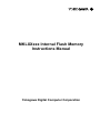
1
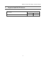
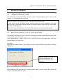
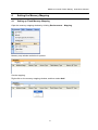
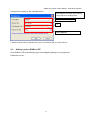
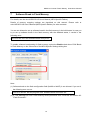
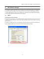
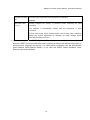
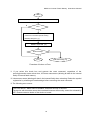
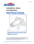
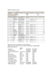
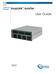
MKLXXxxx Internal Flash Memory
Instructions Manual
Yokogawa Digital Computer Corporation
MKXXxxx Internal Flash Memory Instructions Manual
(1)
No part of this manual may be reproduced or transmitted in any form or by any means,
electronic or mechanical, without the written permission of Yokogawa Digital Computer
Corporation.
(2)
The contents of this manual are subject to change without prior notice due to
improvement of the functionality.
(3)
If any question about the contents of this manual arises, contact Yokogawa Digital
Computer Corporation.
(4)
Yokogawa Digital Computer Corporation shall not be held responsible for direct or
indirect adverse effects resulting from operation of this system irrespective of the
above item (3).
(5)
Product and company names mentioned in this manual are the trademarks of their
respective owners.
© 2013
Yokogawa Digital Computer Corporation.
Printed in Japan
II
All Rights Reserved.
MKXXxxx Internal Flash Memory Instructions Manual
Revision History
Edition
Date of issue
Description
1st Edition
April 04, 2014
• Initial publication
III
MKXXxxx Internal Flash Memory Instructions Manual
Contents
1
Introduction ........................................................................................................... 5
2
Supported Install Kit CD Versions .......................................................................6
3
Advance Preparation ............................................................................................ 7
3.1
When Flash Security is valid .......................................................................................................... 7
3.2
When Correct Address is not set in the Vector Table ..................................................................... 7
4
Setting the Memory Mapping ...............................................................................8
4.1
Setting up Flash Memory Mapping................................................................................................. 8
4.2
Setting up User RAM for ICE.......................................................................................................... 9
5
Erase the Flash Memory ..................................................................................... 10
6
Download to Flash Memory................................................................................ 11
7
Software Break in Flash Memory ....................................................................... 12
8
MPU-Specific Settings ........................................................................................ 13
8.1
9
9.1
RESET.......................................................................................................................................... 13
Notes & Points..................................................................................................... 15
Flowchart of Action on Error ......................................................................................................... 15
9.1.1 Security Error................................................................................................................................ 15
9.2
Watchdog Timer (WDT) ................................................................................................................ 17
9.3
Flash Protection............................................................................................................................ 17
9.4
Software Break in the Internal Flash Memory .............................................................................. 17
IV
MKXXxxx Internal Flash Memory Instructions Manual
1
Introduction
This is a brief manual for writing to on-chip flash memory.
For details of ICE operating instructions, see the microVIEW-PLUS User’s Manual (Common
Edition) and microVIEW-PLUS User’s Manual (MPU-Specific Edition).
5
MKXXxxx Internal Flash Memory Instructions Manual
2
Supported Install Kit CD Versions
Supported Versions
Device Model
MKL26Z64V
6
SLX600
H2X600IK
3.01
1.04
MKXXxxx Internal Flash Memory Instructions Manual
3
3.1
Advance Preparation
When Flash Security is valid
The ICE cannot be connected if flash security is valid. In case the following error occurred, see
Section 9.1 “Flowchart of Action on Error”.
“ICE Error No.fe6: Flash Security is valid. The ICE cannot be connected.
In such cases, release the break setting, and then erase the symbol registration. After that
turning on the Forced unsecured/unprotection on the MPU-specific setting [RESET] dialog box,
and then reset the system.
* Please be aware that all data in the internal flash memory is cleared by forced-release.
3.2
When Correct Address is not set in the Vector Table
microVIEW-PLUS dumps a reset vector area to display a program (disassemble display) after
connecting by reset commands.
If the vector table is in erase (0xFFFFFFFF), 0xFFFFFFFE will be dumped and “ICE Error
No.f58: Sticky error” may occur.
[Provision]
Right-click the Reset button on the toolbar, and then open the Reset Synchronous Settings
dialog box.
Clear the “Display the program in
sync with Reset” check box.
(= does not dump by the reset
command)
After downloading the program to the internal flash memory (correct vector table values are
written), select this check box again.
7
MKXXxxx Internal Flash Memory Instructions Manual
4
Setting the Memory Mapping
4.1
Setting up Flash Memory Mapping
Open the memory mapping window by clicking Environments – Mapping.
Memory map window as below is opened.
Set the mapping.
Right-click on the memory mapping window, and then select Add.
8
MKXXxxx Internal Flash Memory Instructions Manual
Configure the setting as the example below.
Start address of internal flash memory
Using 0x0 as an example here.
Select Flash memory
*1
Select 32bit x 1
* Select the flash memory definition file (.frd) in accordance with your flash memory.
4.2
Setting up User RAM for ICE
User RAM for ICE of the Memory type in the Mapping settings is not supported.
Please do not set.
9
MKXXxxx Internal Flash Memory Instructions Manual
5
Erase the Flash Memory
For details, see the microVIEW-PLUS User’s Manual (MPU-Specific Edition).
Details of memory mapping settings are described on this manual. Please refer to
microVIEW-PLUS User’s Manual (MPU-Specific Edition) for other contents.
Note:
The flash security becomes secure. The connection with ICE is disabled if you reset the system
with this condition.
If you cannot connect the ICE, see Section 9.1 “Flowchart of Action on Error”.
10
MKXXxxx Internal Flash Memory Instructions Manual
6
Download to Flash Memory
For details, see the microVIEW-PLUS User’s Manual (MPU-Specific Edition).
Details of memory mapping settings are described on this manual. Please refer to
microVIEW-PLUS User’s Manual (MPU-Specific Edition) for other contents.
Note:
(1) Please be aware of the followings if you download data to the flash configuration field
(0x400 to 0x40F).
1.
If you download data that secures the flash security , the connection between ICE and
user system becomes disconnected when you reset the system.
If you cannot connect the ICE, see Section 9.1 “Flowchart of Action on Error”.
2. Make sure to download MEEN bit (bit[5:4]) of flash security by switching it to b’11(value
which enables mass erase).
If you set the b'10, you can not connect because it is not possible to security release
from ICE.
3. Make sure to download RESET_PIN_CFG bit (bit[3]) of flash option by switching it to
b’1.
If you choose to Secure the Flash Security by setting the b'0, you can not connect
because it is not possible to security release from ICE.
(2) In case the “ICE Message No.1e41: Flash memory device protection error” occurred, see
Section 9.3 “Flash Protection”.
(3) If the following abnormal end occurs, please download data without setting the user RAM
for ICE or execute the reset command right before the download.
•
Detection of reset by the watchdog timer reset
•
Errors other than erase error or verify error
(4) If you need to download data without setting the user RAM for ICE, execute the reset
command right before the download.
11
MKXXxxx Internal Flash Memory Instructions Manual
7
Software Break in Flash Memory
For details, see the microVIEW-PLUS User’s Manual (MPU-Specific Edition).
Details of memory mapping settings are described on this manual. Please refer to
microVIEW-PLUS User’s Manual (MPU-Specific Edition) for other contents.
You are not allowed to set up software break in the flash memory in the initial state. In case you
try to set up software break in the flash memory with the disabled status, it results in the
following error.
“ICE Error No. 8c4: Set Software Break Verify Error”.
To enable software break setting for flash memory, select the Enable check box of S/W Break
in Flash Memory on the Others tab of the MPU-Specific Settings dialog box.
Note:
(1) Software break to the flash configuration field (0x400 to 0x40F) is not allowed. If you set it,
the following error occurs:
“ICE Error No.fd2: Not the program area. Software break cannot be set.”
(2) If “*ICE Message No.1e41: Flash memory device protection error” occurred, see Section 9.3
“Flash Protection”.
12
MKXXxxx Internal Flash Memory Instructions Manual
8
MPU-Specific Settings
This chapter explains about MPU-specific settings for internal flash memory. For details on
other MPU-specific settings, see the microVIEW-PLUS User’s Manual (MPU-specific Edition).
To set up MPU-specific settings, click on MPU menu, and then click the MPU-specific settings.
Then, the MPU-specific settings window will be opened.
8.1
RESET
Security/Protect Forced-release
For Kinetis products family, you can disable the debug port or protect to not write or erase the
memory by using the setting of flash security byte and flash protection byte within the internal
flash memory.
By using this setting, you can control whether to forcibly release the security or protection by
reset command. Make sure to execute the reset command after the setting.
13
MKXXxxx Internal Flash Memory Instructions Manual
Uncheck the check
ICE cannot be connected if a secured device is detected.
box
(Default)
Select the check
Forcibly releases the security or protection when executing the reset
box (*1)
command.
The selection is automatically cleared after the completion of reset
command.
It does mass erase (erase all data within internal flash) when releasing.
Delete the symbol registration by releasing all break settings before
executing the reset command.
*1: Make sure to connect nSRST signal to ICE connection connector on the user system,
because nSRST is involved with mass erase (deleting all data in the internal flash) which is
operated when releasing the security. For details about connection, see the adviceLUNA
User’s Manual (MPU-Specific Edition). If you clear the nSRST assert checkbox, Flash
Security may not be released.
14
MKXXxxx Internal Flash Memory Instructions Manual
9
Notes & Points
9.1
Flowchart of Action on Error
9.1.1 Security Error
The ICE cannot be connected if flash security is secured. In case the following error occurred,
the flash security may be secured. See the flowchart below and take an action for error.
“ICE Error No.fe6: Flash Security is valid. The ICE cannot be connected.
In such cases, release the break setting, and then erase the symbol registration. After that
turning on the Forced unsecured/unprotection on the MPU-specific setting [RESET] dialog box,
and then reset the system.
* Please be aware that all data in the internal flash memory is cleared by forced-release.
Make sure to connect nSRST signal to ICE connection connector on the user system, because
nSRST is involved with mass erase (deleting all data in the internal flash) which is operated
when releasing the security. For details about connection, see the adviceLUNA User’s Manual
(MPU-Specific Edition).
15
MKXXxxx Internal Flash Memory Instructions Manual
Start
Reset command (Include the ICE connection for the first time)
N
Error
Y
Select the Forced unsecured/unprotection
check box on the MPU-specific setting
[RESET] dialog box. (*1)
RESET command. (*2)
N
End normally?
Y
End abnormally (*3)
End
Flowchart of Action on Error
*1 If you select this check box and execute the reset command, regardless of the
security/protection state at that time, ICE does mass-erase (deleting all data in the internal
flash) of internal flash memory.
*2 It does mass erase (deleting all data in the internal flash) when releasing. Delete the symbol
registration by releasing all break settings before executing the reset command.
*3 The following error occurs:
“ICE Error No.fe7: Mass erase is disabled, and flash security is secured.
The device with this state cannot be connected because the security cannot be released by
ICE. Please contact a dealer of the device or board.
16
MKXXxxx Internal Flash Memory Instructions Manual
9.2
Watchdog Timer (WDT)
You can write in the flash memory even if WDT (Watchdog Timer) is enabled.
WDT is temporarily disabled by an internal process of ICE while the flash memory is written.
(After the writing, it is automatically restored.) Do not enable the WDT on the debug mode.
9.3
Flash Protection
You cannot set the erase, download or software-break in the flash area protected by flash
protection.
*ICE Error No.1e41: Flash memory device protection error occurs.
If the flash configuration field (0x400 to 0x40F) is protected, turn on the Forced
unsecured/unprotection on the MPU-specific setting [RESET] dialog box to release the
protection. After that, reset the system.
9.4
Software Break in the Internal Flash Memory
Software break to the flash configuration field (0x400 to 0x40F) is not allowed. If you set it, the
following error occurs:
“ICE Error No. fd2: Not the program area. Software break cannot be set.”
17