1
ABB component drives
User’s manual
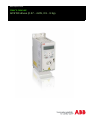
ACS150 drives (0.37…4 kW, 0.5…5 hp)
2
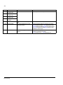
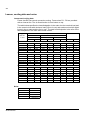
List of related manuals
Drive manuals
ACS310 User’s Manual
Code (English)
1), 2) 3AFE68576032
Option manuals and guides
MUL1-R1 Installation instructions for ACS150,
ACS310, ACS320, ACS350 and ACS355
MFDT-01 FlashDrop user's manual
1), 2) 3AFE68642868
Maintenance manuals
Guide for capacitor reforming in ACS50, ACS55,
ACS150, ACS310, ACS350, ACS355, ACS550,
ACH550 and R1-R4 OINT-/SINT-boards
1)
2)
1), 2) 3AFE68591074
2)
3AFE68735190
Delivered as a printed copy with the drive or optional equipment.
Available in the Internet.
All manuals are available in PDF format on the Internet. See section Further information on the inside of the back cover.
ACS150 drives
0.37…4 kW
0.5…5 hp
User’s manual
3AFE68576032 Rev C
EN
EFFECTIVE: 2011-01-01
© 2010 ABB Oy. All Rights Reserved.
5
Table of contents
List of related manuals . . . . . . . . . . . . . . . . . . . . . . . . . . . . . . . . . . . . . . . . . . . . . . . . . . . . . . . . . . . 2
Table of contents
Safety
What this chapter contains . . . . . . . . . . . . . . . . . . . . . . . . . . . . . . . . . . . . . . . . . . . . . . . . . . . . . . .
Use of warnings . . . . . . . . . . . . . . . . . . . . . . . . . . . . . . . . . . . . . . . . . . . . . . . . . . . . . . . . . . . . . . . .
Safety in installation and maintenance . . . . . . . . . . . . . . . . . . . . . . . . . . . . . . . . . . . . . . . . . . . . . .
Electrical safety . . . . . . . . . . . . . . . . . . . . . . . . . . . . . . . . . . . . . . . . . . . . . . . . . . . . . . . . . . . . .
General safety . . . . . . . . . . . . . . . . . . . . . . . . . . . . . . . . . . . . . . . . . . . . . . . . . . . . . . . . . . . . . .
Safety in start-up and operation . . . . . . . . . . . . . . . . . . . . . . . . . . . . . . . . . . . . . . . . . . . . . . . . . . .
11
11
11
11
12
13
Introduction to the manual
What this chapter contains . . . . . . . . . . . . . . . . . . . . . . . . . . . . . . . . . . . . . . . . . . . . . . . . . . . . . . .
Applicability . . . . . . . . . . . . . . . . . . . . . . . . . . . . . . . . . . . . . . . . . . . . . . . . . . . . . . . . . . . . . . . . . . .
Target audience . . . . . . . . . . . . . . . . . . . . . . . . . . . . . . . . . . . . . . . . . . . . . . . . . . . . . . . . . . . . . . .
Purpose of the manual . . . . . . . . . . . . . . . . . . . . . . . . . . . . . . . . . . . . . . . . . . . . . . . . . . . . . . . . . .
Contents of this manual . . . . . . . . . . . . . . . . . . . . . . . . . . . . . . . . . . . . . . . . . . . . . . . . . . . . . . . . . .
Related documents . . . . . . . . . . . . . . . . . . . . . . . . . . . . . . . . . . . . . . . . . . . . . . . . . . . . . . . . . . . . .
Categorization according to the frame size . . . . . . . . . . . . . . . . . . . . . . . . . . . . . . . . . . . . . . . . . . .
Quick installation and commissioning flowchart . . . . . . . . . . . . . . . . . . . . . . . . . . . . . . . . . . . . . . .
15
15
15
15
15
16
16
17
Operation principle and hardware description
What this chapter contains . . . . . . . . . . . . . . . . . . . . . . . . . . . . . . . . . . . . . . . . . . . . . . . . . . . . . . .
Operation principle . . . . . . . . . . . . . . . . . . . . . . . . . . . . . . . . . . . . . . . . . . . . . . . . . . . . . . . . . . . . .
Product overview . . . . . . . . . . . . . . . . . . . . . . . . . . . . . . . . . . . . . . . . . . . . . . . . . . . . . . . . . . . . . . .
Layout . . . . . . . . . . . . . . . . . . . . . . . . . . . . . . . . . . . . . . . . . . . . . . . . . . . . . . . . . . . . . . . . . . . . .
Power connections and control interfaces . . . . . . . . . . . . . . . . . . . . . . . . . . . . . . . . . . . . . . . . . . . .
Type designation label . . . . . . . . . . . . . . . . . . . . . . . . . . . . . . . . . . . . . . . . . . . . . . . . . . . . . . . . . .
Type designation key . . . . . . . . . . . . . . . . . . . . . . . . . . . . . . . . . . . . . . . . . . . . . . . . . . . . . . . . . . .
19
19
20
20
21
22
22
Mechanical installation
What this chapter contains . . . . . . . . . . . . . . . . . . . . . . . . . . . . . . . . . . . . . . . . . . . . . . . . . . . . . . .
Checking the installation site . . . . . . . . . . . . . . . . . . . . . . . . . . . . . . . . . . . . . . . . . . . . . . . . . . . . . .
Requirements for the installation site . . . . . . . . . . . . . . . . . . . . . . . . . . . . . . . . . . . . . . . . . . . . .
Operation conditions . . . . . . . . . . . . . . . . . . . . . . . . . . . . . . . . . . . . . . . . . . . . . . . . . . . . . . .
Wall . . . . . . . . . . . . . . . . . . . . . . . . . . . . . . . . . . . . . . . . . . . . . . . . . . . . . . . . . . . . . . . . . . . .
Floor . . . . . . . . . . . . . . . . . . . . . . . . . . . . . . . . . . . . . . . . . . . . . . . . . . . . . . . . . . . . . . . . . . . .
Free space around the drive . . . . . . . . . . . . . . . . . . . . . . . . . . . . . . . . . . . . . . . . . . . . . . . . .
Required tools . . . . . . . . . . . . . . . . . . . . . . . . . . . . . . . . . . . . . . . . . . . . . . . . . . . . . . . . . . . . . . . . .
Unpacking . . . . . . . . . . . . . . . . . . . . . . . . . . . . . . . . . . . . . . . . . . . . . . . . . . . . . . . . . . . . . . . . . . . .
23
23
23
23
23
23
23
24
24
Table of contents
6
Checking the delivery . . . . . . . . . . . . . . . . . . . . . . . . . . . . . . . . . . . . . . . . . . . . . . . . . . . . . . . . . . .
Installing . . . . . . . . . . . . . . . . . . . . . . . . . . . . . . . . . . . . . . . . . . . . . . . . . . . . . . . . . . . . . . . . . . . . .
Install the drive . . . . . . . . . . . . . . . . . . . . . . . . . . . . . . . . . . . . . . . . . . . . . . . . . . . . . . . . . . . . .
With screws . . . . . . . . . . . . . . . . . . . . . . . . . . . . . . . . . . . . . . . . . . . . . . . . . . . . . . . . . . . . . .
On DIN rail . . . . . . . . . . . . . . . . . . . . . . . . . . . . . . . . . . . . . . . . . . . . . . . . . . . . . . . . . . . . . .
Horizontally . . . . . . . . . . . . . . . . . . . . . . . . . . . . . . . . . . . . . . . . . . . . . . . . . . . . . . . . . . . . . .
Fasten clamping plates . . . . . . . . . . . . . . . . . . . . . . . . . . . . . . . . . . . . . . . . . . . . . . . . . . . . . . .
25
25
25
25
26
27
28
Planning the electrical installation
What this chapter contains . . . . . . . . . . . . . . . . . . . . . . . . . . . . . . . . . . . . . . . . . . . . . . . . . . . . . . . 29
Implementing the AC power line connection . . . . . . . . . . . . . . . . . . . . . . . . . . . . . . . . . . . . . . . . . 29
Selecting the supply disconnecting device (disconnecting means) . . . . . . . . . . . . . . . . . . . . . . . . 29
European union . . . . . . . . . . . . . . . . . . . . . . . . . . . . . . . . . . . . . . . . . . . . . . . . . . . . . . . . . . . . . 29
Other regions . . . . . . . . . . . . . . . . . . . . . . . . . . . . . . . . . . . . . . . . . . . . . . . . . . . . . . . . . . . . . . . 29
Checking the compatibility of the motor and drive . . . . . . . . . . . . . . . . . . . . . . . . . . . . . . . . . . . . . 30
Selecting the power cables . . . . . . . . . . . . . . . . . . . . . . . . . . . . . . . . . . . . . . . . . . . . . . . . . . . . . . 30
General rules . . . . . . . . . . . . . . . . . . . . . . . . . . . . . . . . . . . . . . . . . . . . . . . . . . . . . . . . . . . . . . . 30
Alternative power cable types . . . . . . . . . . . . . . . . . . . . . . . . . . . . . . . . . . . . . . . . . . . . . . . . . . 31
Motor cable shield . . . . . . . . . . . . . . . . . . . . . . . . . . . . . . . . . . . . . . . . . . . . . . . . . . . . . . . . . . . 31
Additional US requirements . . . . . . . . . . . . . . . . . . . . . . . . . . . . . . . . . . . . . . . . . . . . . . . . . . . . 32
Conduit . . . . . . . . . . . . . . . . . . . . . . . . . . . . . . . . . . . . . . . . . . . . . . . . . . . . . . . . . . . . . . . . . 32
Armored cable / shielded power cable . . . . . . . . . . . . . . . . . . . . . . . . . . . . . . . . . . . . . . . . . 32
Selecting the control cables . . . . . . . . . . . . . . . . . . . . . . . . . . . . . . . . . . . . . . . . . . . . . . . . . . . . . . 33
General rules . . . . . . . . . . . . . . . . . . . . . . . . . . . . . . . . . . . . . . . . . . . . . . . . . . . . . . . . . . . . . . . 33
Relay cable . . . . . . . . . . . . . . . . . . . . . . . . . . . . . . . . . . . . . . . . . . . . . . . . . . . . . . . . . . . . . . . . 33
Routing the cables . . . . . . . . . . . . . . . . . . . . . . . . . . . . . . . . . . . . . . . . . . . . . . . . . . . . . . . . . . . . . 34
Control cable ducts . . . . . . . . . . . . . . . . . . . . . . . . . . . . . . . . . . . . . . . . . . . . . . . . . . . . . . . . . . 34
Protecting the drive, input power cable, motor and motor cable in short-circuit situations and against
thermal overload . . . . . . . . . . . . . . . . . . . . . . . . . . . . . . . . . . . . . . . . . . . . . . . . . . . . . . . . . . . . . . . 35
Protecting the drive and input power cable in short-circuit situations . . . . . . . . . . . . . . . . . . . . 35
Protecting the motor and motor cable in short-circuit situations . . . . . . . . . . . . . . . . . . . . . . . . 35
Protecting the drive, motor cable and input power cable against thermal overload . . . . . . . . . 36
Protecting the motor against thermal overload . . . . . . . . . . . . . . . . . . . . . . . . . . . . . . . . . . . . . 36
Residual current device (RCD) compatibility . . . . . . . . . . . . . . . . . . . . . . . . . . . . . . . . . . . . . . . . . 36
Implementing a bypass connection . . . . . . . . . . . . . . . . . . . . . . . . . . . . . . . . . . . . . . . . . . . . . . . . 36
Protecting the contacts of relay outputs . . . . . . . . . . . . . . . . . . . . . . . . . . . . . . . . . . . . . . . . . . . . . 37
Electrical installation
What this chapter contains . . . . . . . . . . . . . . . . . . . . . . . . . . . . . . . . . . . . . . . . . . . . . . . . . . . . . . .
Checking the insulation of the assembly . . . . . . . . . . . . . . . . . . . . . . . . . . . . . . . . . . . . . . . . . . . .
Drive . . . . . . . . . . . . . . . . . . . . . . . . . . . . . . . . . . . . . . . . . . . . . . . . . . . . . . . . . . . . . . . . . . . . .
Input power cable . . . . . . . . . . . . . . . . . . . . . . . . . . . . . . . . . . . . . . . . . . . . . . . . . . . . . . . . . . .
Motor and motor cable . . . . . . . . . . . . . . . . . . . . . . . . . . . . . . . . . . . . . . . . . . . . . . . . . . . . . . . .
Checking the compatibility with IT (ungrounded) and corner-grounded TN systems . . . . . . . . . . .
Connecting the power cables . . . . . . . . . . . . . . . . . . . . . . . . . . . . . . . . . . . . . . . . . . . . . . . . . . . . .
Connection diagram . . . . . . . . . . . . . . . . . . . . . . . . . . . . . . . . . . . . . . . . . . . . . . . . . . . . . . . . . .
Connection procedure . . . . . . . . . . . . . . . . . . . . . . . . . . . . . . . . . . . . . . . . . . . . . . . . . . . . . . . .
Connecting the control cables . . . . . . . . . . . . . . . . . . . . . . . . . . . . . . . . . . . . . . . . . . . . . . . . . . . .
Table of contents
39
39
39
39
39
40
41
41
42
44
7
I/O terminals . . . . . . . . . . . . . . . . . . . . . . . . . . . . . . . . . . . . . . . . . . . . . . . . . . . . . . . . . . . . . . . .
PNP and NPN configuration for digital inputs . . . . . . . . . . . . . . . . . . . . . . . . . . . . . . . . . . . .
External power supply for digital inputs . . . . . . . . . . . . . . . . . . . . . . . . . . . . . . . . . . . . . . . . .
Default I/O connection diagram . . . . . . . . . . . . . . . . . . . . . . . . . . . . . . . . . . . . . . . . . . . . . . . . .
Connection procedure . . . . . . . . . . . . . . . . . . . . . . . . . . . . . . . . . . . . . . . . . . . . . . . . . . . . . . . .
44
45
45
46
47
Installation checklist
Checking the installation . . . . . . . . . . . . . . . . . . . . . . . . . . . . . . . . . . . . . . . . . . . . . . . . . . . . . . . . . 49
Start-up and control with I/O
What this chapter contains . . . . . . . . . . . . . . . . . . . . . . . . . . . . . . . . . . . . . . . . . . . . . . . . . . . . . . . 51
How to start up the drive . . . . . . . . . . . . . . . . . . . . . . . . . . . . . . . . . . . . . . . . . . . . . . . . . . . . . . . . . 51
How to control the drive through the I/O interface . . . . . . . . . . . . . . . . . . . . . . . . . . . . . . . . . . . . . . 55
Control panel
What this chapter contains . . . . . . . . . . . . . . . . . . . . . . . . . . . . . . . . . . . . . . . . . . . . . . . . . . . . . . .
Integrated control panel . . . . . . . . . . . . . . . . . . . . . . . . . . . . . . . . . . . . . . . . . . . . . . . . . . . . . . . . . .
Overview . . . . . . . . . . . . . . . . . . . . . . . . . . . . . . . . . . . . . . . . . . . . . . . . . . . . . . . . . . . . . . . . . . .
Operation . . . . . . . . . . . . . . . . . . . . . . . . . . . . . . . . . . . . . . . . . . . . . . . . . . . . . . . . . . . . . . . . . .
How to perform common tasks . . . . . . . . . . . . . . . . . . . . . . . . . . . . . . . . . . . . . . . . . . . . . . .
How to start, stop and switch between local and remote control . . . . . . . . . . . . . . . . . . . . . .
How to change the direction of the motor rotation . . . . . . . . . . . . . . . . . . . . . . . . . . . . . . . . .
How to set the frequency reference . . . . . . . . . . . . . . . . . . . . . . . . . . . . . . . . . . . . . . . . . . . .
Output mode . . . . . . . . . . . . . . . . . . . . . . . . . . . . . . . . . . . . . . . . . . . . . . . . . . . . . . . . . . . . . . . .
How to browse the monitored signals . . . . . . . . . . . . . . . . . . . . . . . . . . . . . . . . . . . . . . . . . .
Reference mode . . . . . . . . . . . . . . . . . . . . . . . . . . . . . . . . . . . . . . . . . . . . . . . . . . . . . . . . . . . .
How to view and set the frequency reference . . . . . . . . . . . . . . . . . . . . . . . . . . . . . . . . . . . .
Parameter modes . . . . . . . . . . . . . . . . . . . . . . . . . . . . . . . . . . . . . . . . . . . . . . . . . . . . . . . . . . . .
How to select a parameter and change its value . . . . . . . . . . . . . . . . . . . . . . . . . . . . . . . . . .
How to select the monitored signals . . . . . . . . . . . . . . . . . . . . . . . . . . . . . . . . . . . . . . . . . . .
Changed parameters mode . . . . . . . . . . . . . . . . . . . . . . . . . . . . . . . . . . . . . . . . . . . . . . . . . . . .
How to view and edit changed parameters . . . . . . . . . . . . . . . . . . . . . . . . . . . . . . . . . . . . . .
57
57
58
59
60
61
61
62
63
63
64
64
65
65
66
67
67
Application macros
What this chapter contains . . . . . . . . . . . . . . . . . . . . . . . . . . . . . . . . . . . . . . . . . . . . . . . . . . . . . . .
Overview of macros . . . . . . . . . . . . . . . . . . . . . . . . . . . . . . . . . . . . . . . . . . . . . . . . . . . . . . . . . . . . .
Summary of I/O connections of application macros . . . . . . . . . . . . . . . . . . . . . . . . . . . . . . . . . . . .
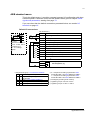
ABB standard macro . . . . . . . . . . . . . . . . . . . . . . . . . . . . . . . . . . . . . . . . . . . . . . . . . . . . . . . . . . . .
Default I/O connections . . . . . . . . . . . . . . . . . . . . . . . . . . . . . . . . . . . . . . . . . . . . . . . . . . . . . . .
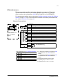
3-wire macro . . . . . . . . . . . . . . . . . . . . . . . . . . . . . . . . . . . . . . . . . . . . . . . . . . . . . . . . . . . . . . . . . .
Default I/O connections . . . . . . . . . . . . . . . . . . . . . . . . . . . . . . . . . . . . . . . . . . . . . . . . . . . . . . .
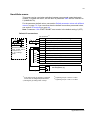
Alternate macro . . . . . . . . . . . . . . . . . . . . . . . . . . . . . . . . . . . . . . . . . . . . . . . . . . . . . . . . . . . . . . . .
Default I/O connections . . . . . . . . . . . . . . . . . . . . . . . . . . . . . . . . . . . . . . . . . . . . . . . . . . . . . . .
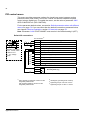
Motor potentiometer macro . . . . . . . . . . . . . . . . . . . . . . . . . . . . . . . . . . . . . . . . . . . . . . . . . . . . . . .
Default I/O connections . . . . . . . . . . . . . . . . . . . . . . . . . . . . . . . . . . . . . . . . . . . . . . . . . . . . . . .
69
69
70
71
71
72
72
73
73
74
74
Table of contents
8
Hand/Auto macro . . . . . . . . . . . . . . . . . . . . . . . . . . . . . . . . . . . . . . . . . . . . . . . . . . . . . . . . . . . . . .
Default I/O connections . . . . . . . . . . . . . . . . . . . . . . . . . . . . . . . . . . . . . . . . . . . . . . . . . . . . . . .
PID control macro . . . . . . . . . . . . . . . . . . . . . . . . . . . . . . . . . . . . . . . . . . . . . . . . . . . . . . . . . . . . . .
Default I/O connections . . . . . . . . . . . . . . . . . . . . . . . . . . . . . . . . . . . . . . . . . . . . . . . . . . . . . . .
User macros . . . . . . . . . . . . . . . . . . . . . . . . . . . . . . . . . . . . . . . . . . . . . . . . . . . . . . . . . . . . . . . . . .
75
75
76
76
77
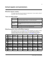
Actual signals and parameters
What this chapter contains . . . . . . . . . . . . . . . . . . . . . . . . . . . . . . . . . . . . . . . . . . . . . . . . . . . . . . . 79
Terms and abbreviations . . . . . . . . . . . . . . . . . . . . . . . . . . . . . . . . . . . . . . . . . . . . . . . . . . . . . . . . 79
Default parameter values with different macros . . . . . . . . . . . . . . . . . . . . . . . . . . . . . . . . . . . . . . . 79
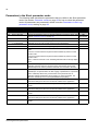
Parameters in the Short parameter mode . . . . . . . . . . . . . . . . . . . . . . . . . . . . . . . . . . . . . . . . . . . 80
99 START-UP DATA . . . . . . . . . . . . . . . . . . . . . . . . . . . . . . . . . . . . . . . . . . . . . . . . . . . . . . . . . . . 80
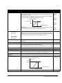
04 FAULT HISTORY . . . . . . . . . . . . . . . . . . . . . . . . . . . . . . . . . . . . . . . . . . . . . . . . . . . . . . . . . . . 81
11 REFERENCE SELECT . . . . . . . . . . . . . . . . . . . . . . . . . . . . . . . . . . . . . . . . . . . . . . . . . . . . . . . 81
12 CONSTANT SPEEDS . . . . . . . . . . . . . . . . . . . . . . . . . . . . . . . . . . . . . . . . . . . . . . . . . . . . . . . . 82
13 ANALOG INPUTS . . . . . . . . . . . . . . . . . . . . . . . . . . . . . . . . . . . . . . . . . . . . . . . . . . . . . . . . . . . 82
20 LIMITS . . . . . . . . . . . . . . . . . . . . . . . . . . . . . . . . . . . . . . . . . . . . . . . . . . . . . . . . . . . . . . . . . . . . 82
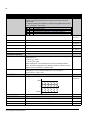
21 START/STOP . . . . . . . . . . . . . . . . . . . . . . . . . . . . . . . . . . . . . . . . . . . . . . . . . . . . . . . . . . . . . . 82
22 ACCEL/DECEL . . . . . . . . . . . . . . . . . . . . . . . . . . . . . . . . . . . . . . . . . . . . . . . . . . . . . . . . . . . . . 83
Actual signals . . . . . . . . . . . . . . . . . . . . . . . . . . . . . . . . . . . . . . . . . . . . . . . . . . . . . . . . . . . . . . . . . 84
01 OPERATING DATA . . . . . . . . . . . . . . . . . . . . . . . . . . . . . . . . . . . . . . . . . . . . . . . . . . . . . . . . . . 84
04 FAULT HISTORY . . . . . . . . . . . . . . . . . . . . . . . . . . . . . . . . . . . . . . . . . . . . . . . . . . . . . . . . . . . 85
Parameters in the Long parameter mode . . . . . . . . . . . . . . . . . . . . . . . . . . . . . . . . . . . . . . . . . . . . 86
10 START/STOP/DIR . . . . . . . . . . . . . . . . . . . . . . . . . . . . . . . . . . . . . . . . . . . . . . . . . . . . . . . . . . . 86
11 REFERENCE SELECT . . . . . . . . . . . . . . . . . . . . . . . . . . . . . . . . . . . . . . . . . . . . . . . . . . . . . . . 89
12 CONSTANT SPEEDS . . . . . . . . . . . . . . . . . . . . . . . . . . . . . . . . . . . . . . . . . . . . . . . . . . . . . . . . 92
13 ANALOG INPUTS . . . . . . . . . . . . . . . . . . . . . . . . . . . . . . . . . . . . . . . . . . . . . . . . . . . . . . . . . . . 94
14 RELAY OUTPUTS . . . . . . . . . . . . . . . . . . . . . . . . . . . . . . . . . . . . . . . . . . . . . . . . . . . . . . . . . . 94
16 SYSTEM CONTROLS . . . . . . . . . . . . . . . . . . . . . . . . . . . . . . . . . . . . . . . . . . . . . . . . . . . . . . . . 96
18 FREQ INPUT . . . . . . . . . . . . . . . . . . . . . . . . . . . . . . . . . . . . . . . . . . . . . . . . . . . . . . . . . . . . . . . 98
20 LIMITS . . . . . . . . . . . . . . . . . . . . . . . . . . . . . . . . . . . . . . . . . . . . . . . . . . . . . . . . . . . . . . . . . . . . 98
21 START/STOP . . . . . . . . . . . . . . . . . . . . . . . . . . . . . . . . . . . . . . . . . . . . . . . . . . . . . . . . . . . . . . 99
22 ACCEL/DECEL . . . . . . . . . . . . . . . . . . . . . . . . . . . . . . . . . . . . . . . . . . . . . . . . . . . . . . . . . . . . 101
25 CRITICAL SPEEDS . . . . . . . . . . . . . . . . . . . . . . . . . . . . . . . . . . . . . . . . . . . . . . . . . . . . . . . . 104
26 MOTOR CONTROL . . . . . . . . . . . . . . . . . . . . . . . . . . . . . . . . . . . . . . . . . . . . . . . . . . . . . . . . 105
30 FAULT FUNCTIONS . . . . . . . . . . . . . . . . . . . . . . . . . . . . . . . . . . . . . . . . . . . . . . . . . . . . . . . . 107
31 AUTOMATIC RESET . . . . . . . . . . . . . . . . . . . . . . . . . . . . . . . . . . . . . . . . . . . . . . . . . . . . . . . 112
32 SUPERVISION . . . . . . . . . . . . . . . . . . . . . . . . . . . . . . . . . . . . . . . . . . . . . . . . . . . . . . . . . . . . 114
33 INFORMATION . . . . . . . . . . . . . . . . . . . . . . . . . . . . . . . . . . . . . . . . . . . . . . . . . . . . . . . . . . . . 115
34 PANEL DISPLAY . . . . . . . . . . . . . . . . . . . . . . . . . . . . . . . . . . . . . . . . . . . . . . . . . . . . . . . . . . 116
40 PROCESS PID SET 1 . . . . . . . . . . . . . . . . . . . . . . . . . . . . . . . . . . . . . . . . . . . . . . . . . . . . . . . 119
99 START-UP DATA . . . . . . . . . . . . . . . . . . . . . . . . . . . . . . . . . . . . . . . . . . . . . . . . . . . . . . . . . . 124
Fault tracing
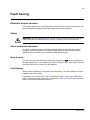
What this chapter contains . . . . . . . . . . . . . . . . . . . . . . . . . . . . . . . . . . . . . . . . . . . . . . . . . . . . . .
Safety . . . . . . . . . . . . . . . . . . . . . . . . . . . . . . . . . . . . . . . . . . . . . . . . . . . . . . . . . . . . . . . . . . . . . .
Alarm and fault indications . . . . . . . . . . . . . . . . . . . . . . . . . . . . . . . . . . . . . . . . . . . . . . . . . . . . . .
How to reset . . . . . . . . . . . . . . . . . . . . . . . . . . . . . . . . . . . . . . . . . . . . . . . . . . . . . . . . . . . . . . . . .
Table of contents
127
127
127
127
9
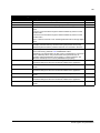
Fault history . . . . . . . . . . . . . . . . . . . . . . . . . . . . . . . . . . . . . . . . . . . . . . . . . . . . . . . . . . . . . . . . . . 127
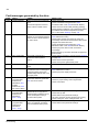
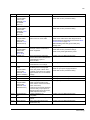
Alarm messages generated by the drive . . . . . . . . . . . . . . . . . . . . . . . . . . . . . . . . . . . . . . . . . . . . 128
Fault messages generated by the drive . . . . . . . . . . . . . . . . . . . . . . . . . . . . . . . . . . . . . . . . . . . . 130
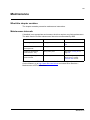
Maintenance
What this chapter contains . . . . . . . . . . . . . . . . . . . . . . . . . . . . . . . . . . . . . . . . . . . . . . . . . . . . . .
Maintenance intervals . . . . . . . . . . . . . . . . . . . . . . . . . . . . . . . . . . . . . . . . . . . . . . . . . . . . . . . . . .
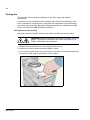
Cooling fan . . . . . . . . . . . . . . . . . . . . . . . . . . . . . . . . . . . . . . . . . . . . . . . . . . . . . . . . . . . . . . . . . .
Fan replacement (R1 and R2) . . . . . . . . . . . . . . . . . . . . . . . . . . . . . . . . . . . . . . . . . . . . . . . . .
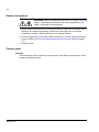
Capacitors . . . . . . . . . . . . . . . . . . . . . . . . . . . . . . . . . . . . . . . . . . . . . . . . . . . . . . . . . . . . . . . . . . .
Reforming the capacitors . . . . . . . . . . . . . . . . . . . . . . . . . . . . . . . . . . . . . . . . . . . . . . . . . . . . .
Power connections . . . . . . . . . . . . . . . . . . . . . . . . . . . . . . . . . . . . . . . . . . . . . . . . . . . . . . . . . . . .
Control panel . . . . . . . . . . . . . . . . . . . . . . . . . . . . . . . . . . . . . . . . . . . . . . . . . . . . . . . . . . . . . . . . .
Cleaning . . . . . . . . . . . . . . . . . . . . . . . . . . . . . . . . . . . . . . . . . . . . . . . . . . . . . . . . . . . . . . . . . .
133
133
134
134
135
135
136
136
136
Technical data
What this chapter contains . . . . . . . . . . . . . . . . . . . . . . . . . . . . . . . . . . . . . . . . . . . . . . . . . . . . . .
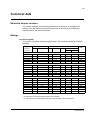
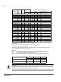
Ratings . . . . . . . . . . . . . . . . . . . . . . . . . . . . . . . . . . . . . . . . . . . . . . . . . . . . . . . . . . . . . . . . . . . . .
Current and power . . . . . . . . . . . . . . . . . . . . . . . . . . . . . . . . . . . . . . . . . . . . . . . . . . . . . . . . . .
Symbols . . . . . . . . . . . . . . . . . . . . . . . . . . . . . . . . . . . . . . . . . . . . . . . . . . . . . . . . . . . . . . . . . .
Sizing . . . . . . . . . . . . . . . . . . . . . . . . . . . . . . . . . . . . . . . . . . . . . . . . . . . . . . . . . . . . . . . . . . . .
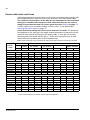
Derating . . . . . . . . . . . . . . . . . . . . . . . . . . . . . . . . . . . . . . . . . . . . . . . . . . . . . . . . . . . . . . . . . .
Temperature derating, I2N . . . . . . . . . . . . . . . . . . . . . . . . . . . . . . . . . . . . . . . . . . . . . . . . . .
Altitude derating, I2N . . . . . . . . . . . . . . . . . . . . . . . . . . . . . . . . . . . . . . . . . . . . . . . . . . . . . .
Switching frequency derating, I2N . . . . . . . . . . . . . . . . . . . . . . . . . . . . . . . . . . . . . . . . . . . .
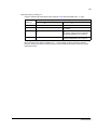
Power cable sizes and fuses . . . . . . . . . . . . . . . . . . . . . . . . . . . . . . . . . . . . . . . . . . . . . . . . . . . . .
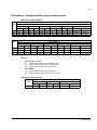
Dimensions, weights and free space requirements . . . . . . . . . . . . . . . . . . . . . . . . . . . . . . . . . . . .
Dimensions and weights
...................................................
Symbols . . . . . . . . . . . . . . . . . . . . . . . . . . . . . . . . . . . . . . . . . . . . . . . . . . . . . . . . . . . . . . . .
Free space requirements . . . . . . . . . . . . . . . . . . . . . . . . . . . . . . . . . . . . . . . . . . . . . . . . . . . . .
Losses, cooling data and noise . . . . . . . . . . . . . . . . . . . . . . . . . . . . . . . . . . . . . . . . . . . . . . . . . . .
Losses and cooling data . . . . . . . . . . . . . . . . . . . . . . . . . . . . . . . . . . . . . . . . . . . . . . . . . . . . . .
Noise . . . . . . . . . . . . . . . . . . . . . . . . . . . . . . . . . . . . . . . . . . . . . . . . . . . . . . . . . . . . . . . . . . . .
Terminal and lead-through data for the power cables . . . . . . . . . . . . . . . . . . . . . . . . . . . . . . . . . .
Terminal data for the control cables . . . . . . . . . . . . . . . . . . . . . . . . . . . . . . . . . . . . . . . . . . . . . . .
Electric power network specification . . . . . . . . . . . . . . . . . . . . . . . . . . . . . . . . . . . . . . . . . . . . . . .
Motor connection data . . . . . . . . . . . . . . . . . . . . . . . . . . . . . . . . . . . . . . . . . . . . . . . . . . . . . . . . . .
Control connection data . . . . . . . . . . . . . . . . . . . . . . . . . . . . . . . . . . . . . . . . . . . . . . . . . . . . . . . .
Brake resistor connection . . . . . . . . . . . . . . . . . . . . . . . . . . . . . . . . . . . . . . . . . . . . . . . . . . . . . . .
Efficiency . . . . . . . . . . . . . . . . . . . . . . . . . . . . . . . . . . . . . . . . . . . . . . . . . . . . . . . . . . . . . . . . . . . .
Degrees of protection . . . . . . . . . . . . . . . . . . . . . . . . . . . . . . . . . . . . . . . . . . . . . . . . . . . . . . . . . .
Ambient conditions . . . . . . . . . . . . . . . . . . . . . . . . . . . . . . . . . . . . . . . . . . . . . . . . . . . . . . . . . . . .
Materials . . . . . . . . . . . . . . . . . . . . . . . . . . . . . . . . . . . . . . . . . . . . . . . . . . . . . . . . . . . . . . . . . . . .
Applicable standards . . . . . . . . . . . . . . . . . . . . . . . . . . . . . . . . . . . . . . . . . . . . . . . . . . . . . . . . . . .
CE marking . . . . . . . . . . . . . . . . . . . . . . . . . . . . . . . . . . . . . . . . . . . . . . . . . . . . . . . . . . . . . . . . . .
Compliance with the European EMC Directive . . . . . . . . . . . . . . . . . . . . . . . . . . . . . . . . . . . . .
Compliance with the EN 61800-3:2004 . . . . . . . . . . . . . . . . . . . . . . . . . . . . . . . . . . . . . . . . . . . . .
Definitions . . . . . . . . . . . . . . . . . . . . . . . . . . . . . . . . . . . . . . . . . . . . . . . . . . . . . . . . . . . . . . . . .
137
137
137
138
138
138
138
138
139
140
141
141
141
141
142
142
142
143
143
144
144
146
146
146
146
147
147
148
148
148
148
148
Table of contents
10
Compliance . . . . . . . . . . . . . . . . . . . . . . . . . . . . . . . . . . . . . . . . . . . . . . . . . . . . . . . . . . . . . . .
Category C1 . . . . . . . . . . . . . . . . . . . . . . . . . . . . . . . . . . . . . . . . . . . . . . . . . . . . . . . . . . . .
Category C2 . . . . . . . . . . . . . . . . . . . . . . . . . . . . . . . . . . . . . . . . . . . . . . . . . . . . . . . . . . . .
Category C3 . . . . . . . . . . . . . . . . . . . . . . . . . . . . . . . . . . . . . . . . . . . . . . . . . . . . . . . . . . . .
UL marking . . . . . . . . . . . . . . . . . . . . . . . . . . . . . . . . . . . . . . . . . . . . . . . . . . . . . . . . . . . . . . . . . .
UL checklist . . . . . . . . . . . . . . . . . . . . . . . . . . . . . . . . . . . . . . . . . . . . . . . . . . . . . . . . . . . . .
C-Tick marking . . . . . . . . . . . . . . . . . . . . . . . . . . . . . . . . . . . . . . . . . . . . . . . . . . . . . . . . . . . . . . .
RoHS marking . . . . . . . . . . . . . . . . . . . . . . . . . . . . . . . . . . . . . . . . . . . . . . . . . . . . . . . . . . . . . . .
Brake resistors . . . . . . . . . . . . . . . . . . . . . . . . . . . . . . . . . . . . . . . . . . . . . . . . . . . . . . . . . . . . . . .
Selecting the brake resistor . . . . . . . . . . . . . . . . . . . . . . . . . . . . . . . . . . . . . . . . . . . . . . . . . . .
Selecting the brake resistor cables . . . . . . . . . . . . . . . . . . . . . . . . . . . . . . . . . . . . . . . . . . . . .
Placing the brake resistor . . . . . . . . . . . . . . . . . . . . . . . . . . . . . . . . . . . . . . . . . . . . . . . . . . . .
Protecting the system in brake circuit fault situations . . . . . . . . . . . . . . . . . . . . . . . . . . . . . . .
Protection of the system in cable and brake resistor short-circuit situations . . . . . . . . . . . .
Protection of the system in brake resistor overheating situations . . . . . . . . . . . . . . . . . . . .
Electrical installation . . . . . . . . . . . . . . . . . . . . . . . . . . . . . . . . . . . . . . . . . . . . . . . . . . . . . . . .
Start-up . . . . . . . . . . . . . . . . . . . . . . . . . . . . . . . . . . . . . . . . . . . . . . . . . . . . . . . . . . . . . . . . . .
149
149
149
149
150
150
150
150
151
151
153
153
153
153
153
153
154
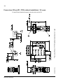
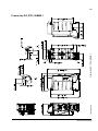
Dimension drawings
Frame sizes R0 and R1, IP20 (cabinet installation) / UL open . . . . . . . . . . . . . . . . . . . . . . . . . . .
Frame sizes R0 and R1, IP20 / NEMA 1 . . . . . . . . . . . . . . . . . . . . . . . . . . . . . . . . . . . . . . . . . . .
Frame size R2, IP20 (cabinet installation) / UL open . . . . . . . . . . . . . . . . . . . . . . . . . . . . . . . . . .
Frame size R2, IP20 / NEMA 1 . . . . . . . . . . . . . . . . . . . . . . . . . . . . . . . . . . . . . . . . . . . . . . . . . .
156
157
158
159
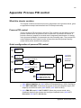
Appendix: Process PID control
What this chapter contains . . . . . . . . . . . . . . . . . . . . . . . . . . . . . . . . . . . . . . . . . . . . . . . . . . . . . .
Process PID control . . . . . . . . . . . . . . . . . . . . . . . . . . . . . . . . . . . . . . . . . . . . . . . . . . . . . . . . . . .
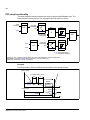
Quick configuration of process PID control . . . . . . . . . . . . . . . . . . . . . . . . . . . . . . . . . . . . . . . . .
Pressure boost pump . . . . . . . . . . . . . . . . . . . . . . . . . . . . . . . . . . . . . . . . . . . . . . . . . . . . . . . .
How to scale the PID actual (feedback) signal 0…10 bar / 4…20 mA . . . . . . . . . . . . . . . .
How to scale the PID setpoint signal . . . . . . . . . . . . . . . . . . . . . . . . . . . . . . . . . . . . . . . . . .
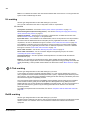
PID sleep functionality . . . . . . . . . . . . . . . . . . . . . . . . . . . . . . . . . . . . . . . . . . . . . . . . . . . . . . . . .
161
161
161
162
163
163
164
Further information
Product and service inquiries . . . . . . . . . . . . . . . . . . . . . . . . . . . . . . . . . . . . . . . . . . . . . . . . . . . .
Product training . . . . . . . . . . . . . . . . . . . . . . . . . . . . . . . . . . . . . . . . . . . . . . . . . . . . . . . . . . . . . .
Providing feedback on ABB Drives manuals . . . . . . . . . . . . . . . . . . . . . . . . . . . . . . . . . . . . . . . .
Document library on the Internet . . . . . . . . . . . . . . . . . . . . . . . . . . . . . . . . . . . . . . . . . . . . . . . . .
Table of contents
169
169
169
169
11
Safety
What this chapter contains
The chapter contains safety instructions that you must follow when installing,
operating and servicing the drive. If ignored, physical injury or death may follow, or
damage may occur to the drive, motor or driven equipment. Read the safety
instructions before you work on the drive.
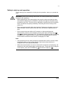
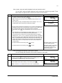
Use of warnings
Warnings caution you about conditions which can result in serious injury or death
and/or damage to the equipment, and advise on how to avoid the danger. The
warning symbols are used as follows:
Electricity warning warns of hazards from electricity which can cause
physical injury and/or damage to the equipment.
General warning warns about conditions, other than those caused by
electricity, which can result in physical injury and/or damage to the
equipment.
Safety in installation and maintenance
These warnings are intended for all who work on the drive, motor cable or motor.
Electrical safety
WARNING! Ignoring the instructions can cause physical injury or death, or damage
to the equipment.
Only qualified electricians are allowed to install and maintain the drive!
• Never work on the drive, motor cable or motor when input power is applied. After
disconnecting the input power, always wait for 5 minutes to let the intermediate
circuit capacitors discharge before you start working on the drive, motor or motor
cable.
Always ensure by measuring with a multimeter (impedance at least 1 Mohm) that:
1. There is no voltage between the drive input phases U1, V1 and W1 and the
ground.
2. There is no voltage between terminals BRK+ and BRK- and the ground.
• Do not work on the control cables when power is applied to the drive or to the
external control circuits. Externally supplied control circuits may carry dangerous
voltage even when the input power of the drive is switched off.
• Do not make any insulation or voltage withstand tests on the drive.
Safety
12
• Disconnect the internal EMC filter when installing the drive on an IT system (an
ungrounded power system or a high-resistance-grounded [over 30 ohms] power
system), otherwise the system will be connected to ground potential through the
EMC filter capacitors. This may cause danger or damage the drive. See page 40.
Note: When the internal EMC filter is disconnected, the drive is not EMC
compatible.
• Disconnect the internal EMC filter when installing the drive on a corner-grounded
TN system, otherwise the drive will be damaged. See page 40. Note: When the
internal EMC filter is disconnected, the drive is not EMC compatible.
• All ELV (extra low voltage) circuits connected to the drive must be used within a
zone of equipotential bonding, ie within a zone where all simultaneously
accessible conductive parts are electrically connected to prevent hazardous
voltages appearing between them. This is accomplished by a proper factory
grounding.
Note:
Even when the motor is stopped, dangerous voltage is present at the power circuit
terminals U1, V1, W1 and U2, V2, W2 and BRK+ and BRK-.
General safety
WARNING! Ignoring the following instructions can cause physical injury or death, or
damage to the equipment.
• The drive is not field repairable. Never attempt to repair a malfunctioning drive;
contact your local ABB representative or Authorized Service Center for
replacement.
• Make sure that dust from drilling does not enter the drive during the installation.
Electrically conductive dust inside the drive may cause damage or lead to
malfunction.
• Ensure sufficient cooling.
Safety
13
Safety in start-up and operation
These warnings are intended for all who plan the operation, start up or operate the
drive.
WARNING! Ignoring the following instructions can cause physical injury or death, or
damage to the equipment.
• Before adjusting the drive and putting it into service, make sure that the motor
and all driven equipment are suitable for operation throughout the speed range
provided by the drive. The drive can be adjusted to operate the motor at speeds
above and below the speed provided by connecting the motor directly to the
power line.
• Do not activate automatic fault reset functions if dangerous situations can occur.
When activated, these functions reset the drive and resume operation after a
fault.
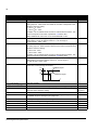
• Do not control the motor with an AC contactor or disconnecting device
(disconnecting means); use instead the control panel start and stop keys
and
or external commands (I/O). The maximum allowed number of charging
cycles of the DC capacitors (that is, power-ups by applying power) is two per
minute and the maximum total number of chargings is 15 000.
Note:
• If an external source for start command is selected and it is ON, the drive starts
immediately after an input voltage break or fault reset unless the drive is
configured for 3-wire (a pulse) start/stop.
• When the control location is not set to local (LOC not shown on the display), the
stop key on the control panel does not stop the drive. To stop the drive using the
control panel, press the LOC/REM key LOC
.
REM and then the stop key
Safety
14
Safety
15
Introduction to the manual
What this chapter contains
The chapter describes applicability, the target audience and purpose of this manual.
It describes the contents of this manual and refers to a list of related manuals for
more information. It also contains a flowchart of steps for checking the delivery,
installing and commissioning the drive. The flowchart refers to chapters/sections in
this manual.
Applicability
The manual is applicable to the ACS150 drive firmware version 1.35b or later. See
parameter 3301 FIRMWARE on page 115.
Target audience
The reader is expected to know the fundamentals of electricity, wiring, electrical
components and electrical schematic symbols.
This manual is written for readers worldwide. Both SI and imperial units are shown.
Special US instructions for installations in the United States are given.
Purpose of the manual
This manual provides information needed for planning the installation, installing,
commissioning, using and servicing the drive.
Contents of this manual
The manual consists of the following chapters:
• Safety (page 11) gives safety instructions you must follow when installing,
commissioning, operating and servicing the drive.
• Introduction to the manual (this chapter, page 15) describes applicability, target
audience, purpose and contents of this manual. It also contains a quick
installation and commissioning flowchart.
• Operation principle and hardware description (page 19) describes the operation
principle, layout, type designation label and type designation information. It also
shows a general diagram of power connections and control interfaces.
• Mechanical installation (page 23) tells how to check the installation site, unpack,
check the delivery and install the drive mechanically.
• Planning the electrical installation (page 29) tells how to check the compatibility of
the motor and the drive and select cables, protections and cable routing.
Introduction to the manual
16
• Electrical installation (page 39) tells how to check the insulation of the assembly
and the compatibility with IT (ungrounded) and corner-grounded TN systems as
well as connect power cables and control cables.
• Installation checklist (page 49) contains a checklist for checking the mechanical
and electrical installation of the drive.
• Start-up and control with I/O (page 51) tells how to start, stop, change the
direction of the motor rotation and adjust the motor speed through the I/O
interface.
• Control panel (page 57) describes the control panel keys, LED indicators and
display fields and tells how to use the panel for control, monitoring and changing
the settings.
• Application macros (page 69) gives a brief description of each application macro
together with a wiring diagram showing the default control connections. It also
explains how to save a user macro and how to recall it.
• Actual signals and parameters (page 79) describes actual signals and
parameters. It also lists the default values for the different macros.
• Fault tracing (page 127) tells how to reset faults and view fault history. It lists all
alarm and fault messages including the possible cause and corrective actions.
• Maintenance (page 133) contains preventive maintenance instructions.
• Technical data (page 137) contains technical specifications of the drive, such as
ratings, sizes and technical requirements as well as provisions for fulfilling the
requirements for CE and other marks.
• Dimension drawings (page 155) shows dimension drawings of the drive.
• Appendix: Process PID control (page 161) contains instructions on quick
configuration of the process control, gives an application example and describes
the PID sleep functionality.
• Further information (page 169) (inside of the back cover, page 169) tells how to
make product and service inquiries, get information on product training, provide
feedback on ABB Drives manuals and find documents on the Internet.
Related documents
See List of related manuals on page 2 (inside of the front cover).
Categorization according to the frame size
The ACS150 is manufactured in frame sizes R0...R2. Some instructions and other
information which only concern certain frame sizes are marked with the symbol of
the frame size (R0...R2). To identify the frame size of your drive, see the table in
section Ratings on page 137.
Introduction to the manual
17
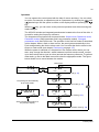
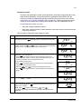
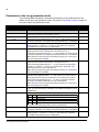
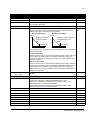
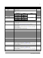
Quick installation and commissioning flowchart
Task
Identify the frame size of your drive: R0…R2.
See
Operation principle and hardware description:
Type designation key on page 22
Technical data: Ratings on page 137
Plan the installation: select the cables, etc.
Planning the electrical installation on page 29
Check the ambient conditions, ratings and required
cooling air flow.
Technical data on page 137
Unpack and check the drive.
Mechanical installation: Unpacking on page 24
If the drive is connected to an IT (ungrounded) or
Operation principle and hardware description:
corner-grounded system, check that the internal EMC Type designation key on page 22 Electrical
filter is not connected.
installation: Checking the compatibility with IT
(ungrounded) and corner-grounded TN
systems on page 40
Install the drive on a wall or in a cabinet.
Mechanical installation on page 23
Route the cables.
Planning the electrical installation: Routing the
cables on page 34
Check the insulation of the input cable and the motor Electrical installation: Checking the insulation of
and the motor cable.
the assembly on page 39
Connect the power cables.
Electrical installation: Connecting the power
cables on page 41
Connect the control cables.
Electrical installation: Connecting the control
cables on page 44
Check the installation.
Installation checklist on page 49
Commission the drive.
Start-up and control with I/O on page 51
Introduction to the manual
18
Introduction to the manual
19
Operation principle and hardware description
What this chapter contains
The chapter briefly describes the operation principle, layout, type designation label
and type designation information. It also shows a general diagram of power
connections and control interfaces.
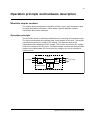
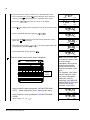
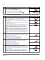
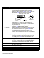
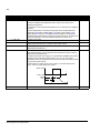
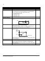
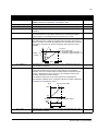
Operation principle
The ACS150 is a wall or cabinet mountable drive for controlling AC induction motors.
The figure below shows the simplified main circuit diagram of the drive. The rectifier
converts three-phase AC voltage to DC voltage. The capacitor bank of the
intermediate circuit stabilizes the DC voltage. The inverter converts the DC voltage
back to AC voltage for the AC motor. The brake chopper connects the external brake
resistor to the intermediate DC circuit when the voltage in the circuit exceeds its
maximum limit.
U1
Rectifier
Capacitor
bank
AC supply V1
W1
Inverter
U2
V2
W2
M
3~
AC motor
Brake chopper
BRK- BRK+
Operation principle and hardware description
20
Product overview
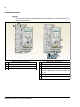
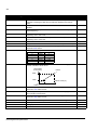
Layout
The layout of the drive is presented below. The construction of frame sizes R0…R2
varies to some extent.
1
2
3
4
5
6
7
8
9
12
2
12
Without plates (R0 and R1)
10
11
With plates (R0 and R1)
1 Cooling outlet through top cover
5 FlashDrop connection
2 Mounting holes
6 EMC filter grounding screw (EMC)
3 Integrated control panel
7 Varistor grounding screw (VAR)
4 Integrated potentiometer
8 I/O connections
9 Input power connection (U1, V1, W1), brake resistor
connection (BRK+, BRK-) and motor connection (U2,
V2, W2)
10 I/O clamping plate
11 Clamping plate
12 Clamps
Operation principle and hardware description
21
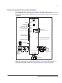
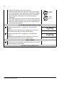
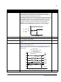
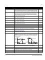
Power connections and control interfaces
The diagram gives an overview of connections. The I/O connections are
parameterable. See chapter Application macros on page 69 for the I/O connections
for the different macros and chapter Electrical installation on page 39 for installation
in general.
Potentiometer
Screen
SCR
AI
Analog input
0…10 V
I
U
GND
Reference voltage
+10 V DC, max. 10 mA
S1
AI
+10V
COM
+24 V
Aux. voltage output
+24 V DC, max. 200 mA
NC
GND
NO
COM
Relay output
250 V AC / 30 V DC / 6 A
DI1
PROGRAMMABLE
DIGITAL INPUTS
DI2
DI3
DI4
EMC
EMC filter grounding screw
DI5
VAR
Varistor grounding screw
PE
L1
PE
U1
U2
L2
V1
V2
L3
W1
W2
Brake chopper
DI5 can also be used
as a frequency input
FlashDrop
3-phase
power
supply,
200…480
V AC
Input
choke
6
EMC
filter
BRK+ BRK-
t°
M
3~
Output
choke
AC motor
Brake resistor
Note: For 1-phase power supply, connect power to U1/L and V1/N terminals. For
connecting the power cables, see Connecting the power cables on page 41.
Operation principle and hardware description
22
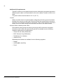
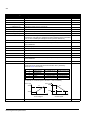
Type designation label
The type designation label is attached to the left side of the drive. An example label
and explanation of the label contents are shown below.
1
$% &'( ) #*+,$-
'0
0 3
0
'%
%
%
2
1
! ! ""!#
///////////////////////
& .++
////
MYYWWRXXXX
4
1" 2#" ////////////////////////////
5
4"581818
034
4"581818
RoHS
#"245
6
1 2'0
"3",0 60&0 7- 2 5 1 Type designation, see section Type designation key on
page 22
2 Degree of protection by enclosure (IP and UL/NEMA)
3 Nominal ratings, see section Ratings on page 137.
4 Serial number of format MYYWWRXXXX, where
M:
Manufacturer
YY:
09, 10, 11, … for 2009, 2010, 2011, …
WW:
01, 02, 03, … for week 1, week 2, week 3, …
R:
A, B, C, … for product revision number
XXXX: Integer starting every week from 0001
Type designation label
5 ABB MRP code of the drive
6 CE marking and C-Tick, C-UL US and RoHS marks
(the label of your drive shows the valid markings)
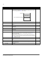
Type designation key
The type designation contains information on the specifications and configuration of
the drive. You find the type designation label attached to the drive. The first digits
from the left express the basic configuration, for example ACS150-03E-08A8-4. The
explanations of the type designation label selections are described below.
ACS150-03E-08A8-4
ACS150 product series
1-phase/3-phase
01 = 1-phase input
03 = 3-phase input
Configuration
E = EMC filter connected, 50 Hz frequency
U = EMC filter disconnected, 60 Hz frequency
Output current rating
In format xxAy, where xx indicates the integer part and y the fractional part,
for example, 08A8 means 8.8 A.
For more information, see section Ratings on page 137.
Input voltage range
2 = 200…240 V AC
4 = 380…480 V AC
Operation principle and hardware description
23
Mechanical installation
What this chapter contains
The chapter describes tells how to check the installation site, unpack, check the
delivery and install the drive mechanically.
Checking the installation site
The ACS150 may be installed on the wall or in a cabinet. Check the enclosure
requirements for the need to use the NEMA 1 option in wall installations (see chapter
Technical data on page 137).
The drive can be mounted in four different ways:
a) vertical back mounting (all frame sizes)
b) horizontal back mounting (frame sizes R1…R2)
c) vertical side mounting (all frame sizes)
d) vertical DIN rail mounting (all frame sizes).
Check the installation site according to the requirements below. Refer to chapter
Dimension drawings on page 155 for frame details.
Requirements for the installation site
Operation conditions
See chapter Technical data on page 137 for the allowed operation conditions of the
drive.
Wall
The wall should be as close to vertical and even as possible, of non-flammable
material and strong enough to carry the weight of the drive.
Floor
The floor/material below the installation should be non-flammable.
Free space around the drive
In vertical mounting, the required free space for cooling above and below the drive is
75 mm (3 in). No free space is required on the sides of the drive, so the drives can
be mounted immediately next to each other.
When you install the drive horizontally, you need to have free space both above and
below AND on the sides of the drive. For more information, see the figure in section
Horizontally on page 27.
Mechanical installation
24
Required tools
To install the drive, you need the following tools:
• screwdrivers (as appropriate for the mounting hardware used)
• wire stripper
• tape measure
• drill (if the drive is installed with screws/bolts)
• mounting hardware: screws or bolts (if the drive is installed with screws/bolts). For
the number of screws/bolts, see section With screws on page 25.
Unpacking
The drive (1) is delivered in a package that also contains the following items (frame
size R0 shown in the figure):
• plastic bag (2) including clamping plate, I/O clamping plate, clamps and screws
• mounting template, integrated into the package (3)
• user’s manual (4).
3
1
4
2
Mechanical installation
25
Checking the delivery
Check that there are no signs of damage. Notify the shipper immediately if damaged
components are found.
Before attempting installation and operation, check the information on the type
designation label of the drive to verify that the drive is of the correct type. See
section Type designation label on page 22.
Installing
The instructions in this manual cover drives with the IP20 degree of protection. To
comply with NEMA 1, use the MUL1-R1 option kit, which is delivered with
multilingual installation instructions (3AFE68642868).
Install the drive
Install the drive with screws or on a DIN rail as appropriate.
Note: Make sure that dust from drilling does not enter the drive during the
installation.
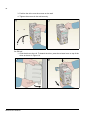
With screws
For installing the drive horizontally, see section Horizontally on page 27.
1. Mark the hole locations using for example, the mounting template cut out from the
package. The locations of the holes are also shown in the drawings in chapter
Dimension drawings on page 155. The number and location of the holes used
depend on how the drive is installed:
a) back mounting: four holes
b) side mounting: three holes; one of the bottom holes is located in the clamping
plate.
2. Fix the screws or bolts to the marked locations.
1
2
2
Mechanical installation
26
3. Position the drive onto the screws on the wall.
4. Tighten the screws in the wall securely.
3
4
On DIN rail
1. Click the drive to the rail. To detach the drive, press the release lever on top of the
drive as shown in Figure 1b.
1
Mechanical installation
1b
27
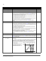
Horizontally
You can install the drive horizontally with screws (only back mounting, four holes).
For the installation instructions, see section With screws on page 25.
Note: For the required free space, see the following figure.
WARNING! Horizontal mounting is permitted only for frame sizes R1 and R2
because they include a cooling fan. Position the drive so that the connectors at the
bottom of the drive are situated to the right and the fan to the left as shown in the
following figure. Do not install frame size R0 horizontally!
25 cm
75 cm
75 cm
25 cm
Mechanical installation
28
Fasten clamping plates
Note: Make sure that you do not throw the clamping plates away as they are
required for proper grounding of the power and control cables.
1. Fasten the clamping plate to the plate at the bottom of the drive with the provided
screws.
2. Fasten the I/O clamping plate to the clamping plate with the provided screws.
1
Mechanical installation
2
29
Planning the electrical installation
What this chapter contains
The chapter contains the instructions that you must follow when when checking the
compatibility of the motor and drive, and selecting cables, protections, cable routing
and way of operation for the drive.
Note: The installation must always be designed and made according to applicable
local laws and regulations. ABB does not assume any liability whatsoever for any
installation which breaches the local laws and/or other regulations. Furthermore, if
the recommendations given by ABB are not followed, the drive may experience
problems that the warranty does not cover.
Implementing the AC power line connection
See the requirements in section Electric power network specification on page 144.
Use a fixed connection to the AC power line.
WARNING! As the leakage current of the device typically exceeds 3.5 mA, a fixed
installation is required according to IEC 61800-5-1.
Selecting the supply disconnecting device (disconnecting means)
Install a hand-operated supply disconnecting device (disconnecting means) between
the AC power source and the drive. The disconnecting device must be of a type that
can be locked to the open position for installation and maintenance work.
European union
To meet the European Union Directives, according to standard EN 60204-1, Safety
of Machinery, the disconnecting device must be one of the following types:
• a switch-disconnector of utilization category AC-23B (EN 60947-3)
• a disconnector having an auxiliary contact that in all cases causes switching
devices to break the load circuit before the opening of the main contacts of the
disconnector (EN 60947-3)
• a circuit breaker suitable for isolation in accordance with EN 60947-2.
Other regions
The disconnecting device must conform to the applicable safety regulations.
Planning the electrical installation
30
Checking the compatibility of the motor and drive
Check that the 3-phase AC induction motor and the drive are compatible according
to the rating table in section Ratings on page 137. The table lists the typical motor
power for each drive type.
Selecting the power cables
General rules
Dimension the input power and motor cables according to local regulations.
• The input power and the motor cables must be able to carry the corresponding
load currents. See section Ratings on page 137 for the rated currents.
• The cable must be rated for at least 70 °C maximum permissible temperature of
the conductor in continuous use. For US, see section Additional US requirements
on page 32.
• The conductivity of the PE conductor must be equal to that of the phase
conductor (same cross-sectional area).
• 600 V AC cable is accepted for up to 500 V AC.
• Refer to chapter Technical data on page 137 for the EMC requirements.
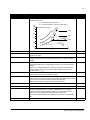
A symmetrical shielded motor cable (see the following figure) must be used to meet
the EMC requirements of the CE and C-Tick marks.
A four-conductor system is allowed for input cabling, but a shielded symmetrical
cable is recommended.
Compared to a four-conductor system, the use of a symmetrical shielded cable
reduces electromagnetic emission of the whole drive system as well as motor
bearing currents and wear.
Planning the electrical installation
31
Alternative power cable types
Power cable types that can be used with the drive are presented below.
Allowed as motor cables
(recommended for input cables also)
Symmetrical shielded cable: three phase conductors,
a concentric or otherwise symmetrically constructed
PE conductor and a shield
PE conductor
and shield
Note: A separate PE conductor is required if the
conductivity of the cable shield is not sufficient for the
purpose.
Shield
Shield
PE
PE
Allowed as input cables
Shield
A four-conductor system: three phase conductors and
a protective conductor
PE
PE
Not allowed for motor cabling: Separate cables for
each phase and PE
PE
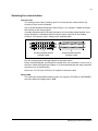
Motor cable shield
To function as a protective conductor, the shield must have the same cross-sectional
area as the phase conductors when they are made of the same metal.
To effectively suppress radiated and conducted radio-frequency emissions, the
shield conductivity must be at least 1/10 of the phase conductor conductivity. The
requirements are easily met with a copper or aluminium shield. The minimum
requirement of the motor cable shield of the drive is shown below. It consists of a
concentric layer of copper wires. The better and tighter the shield, the lower the
emission level and bearing currents.
Insulation jacket
Copper wire screen
Cable core
Planning the electrical installation
32
Additional US requirements
Type MC continuous corrugated aluminium armor cable with symmetrical grounds or
shielded power cable is recommended for the motor cables if metallic conduit is not
used.
The power cables must be rated for 75 °C (167 °F).
Conduit
Where conduits must be coupled together, bridge the joint with a ground conductor
bonded to the conduit on each side of the joint. Bond the conduits also to the drive
enclosure. Use separate conduits for input power, motor, brake resistors and control
wiring. Do not run motor wiring from more than one drive in the same conduit.
Armored cable / shielded power cable
Six-conductor (three phases and three ground) type MC continuous corrugated
aluminium armor cable with symmetrical grounds is available from the following
suppliers (trade names in parentheses):
• Anixter Wire & Cable (Philsheath)
• BICC General Corp (Philsheath)
• Rockbestos Co. (Gardex)
• Oaknite (CLX).
Shielded power cables are available from the following suppliers:
• Belden
• LAPPKABEL (ÖLFLEX)
• Pirelli.
Planning the electrical installation
33
Selecting the control cables
General rules
The analog control cable (if analog input AI is used) and the cable used for the
frequency input must be shielded.
Use a double-shielded twisted pair cable (Figure a, for example, JAMAK by Draka
NK Cables) for the analog signal.
A double-shielded cable is the best alternative for low-voltage digital signals, but a
single-shielded or unshielded twisted multipair cable (Figure b) is also usable.
However, for frequency input, always use a shielded cable.
a
Double-shielded twisted
multipair cable
b
Single-shielded twisted
multipair cable
Run the analog signal and digital signals in separate cables.
Relay-controlled signals, providing their voltage does not exceed 48 V, can be run in
the same cables as digital input signals. It is recommended that the relay-controlled
signals are run as twisted pairs.
Never mix 24 V DC and 115/230 V AC signals in the same cable.
Relay cable
The cable type with braided metallic screen (for example, ÖLFLEX by LAPPKABEL)
has been tested and approved by ABB.
Planning the electrical installation
34
Routing the cables
Route the motor cable away from other cable routes. Motor cables of several drives
can be run in parallel installed next to each other. It is recommended that the motor
cable, input power cable and control cables are installed on separate trays. Avoid
long parallel runs of motor cables with other cables to decrease electromagnetic
interference caused by the rapid changes in the drive output voltage.
Where control cables must cross power cables make sure that they are arranged at
an angle as near to 90 degrees as possible.
The cable trays must have good electrical bonding to each other and to the
grounding electrodes. Aluminium tray systems can be used to improve local
equalizing of potential.
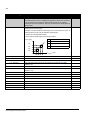
A diagram of the cable routing is shown below.
Motor cable
Drive
Power cable
Input power cable
min. 200 mm (8 in)
min. 300 mm (12 in)
Motor cable
90 °
min. 500 mm (20 in)
Control cables
Control cable ducts
24 V 230 V
Not allowed unless the 24 V cable is
insulated for 230 V or insulated with an
insulation sleeving for 230 V.
Planning the electrical installation
24 V
230 V
Lead 24 V and 230 V control cables in
separate ducts inside the cabinet.
35
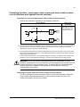
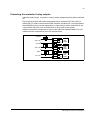
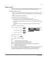
Protecting the drive, input power cable, motor and motor cable in shortcircuit situations and against thermal overload
Protecting the drive and input power cable in short-circuit situations
Arrange the protection according to the following guidelines.
Circuit diagram
Distribution
board
1)
Drive
M
3~
I>
2)
Input cable
Short-circuit
protection
Protect the drive and
input cable with fuses or
a circuit breaker. See
footnotes 1) and 2).
M
3~
1) Size the fuses according to instructions given in chapter Technical data on page 137. The fuses protect
the input cable in short-circuit situations, restrict drive damage and prevent damage to adjoining
equipment in case of a short circuit inside the drive.
2) Circuit breakers which have been tested by ABB with the ACS150 can be used. Fuses must be used
with other circuit breakers. Contact your local ABB representative for the approved breaker types and
supply network characteristics.
The protective characteristics of circuit breakers depend on the type, construction and settings of the
breakers. There are also limitations pertaining to the short-circuit capacity of the supply network.
WARNING! Due to the inherent operating principle and construction of circuit
breakers, independent of the manufacturer, hot ionized gases may escape from the
breaker enclosure in case of a short circuit. To ensure safe use, special attention
must be paid to the installation and placement of the breakers. Follow the
manufacturer’s instructions.
Protecting the motor and motor cable in short-circuit situations
The drive protects the motor and motor cable in a short-circuit situation when the
motor cable is dimensioned according to the nominal current of the drive. No
additional protection devices are needed.
Planning the electrical installation
36
Protecting the drive, motor cable and input power cable against thermal overload
The drive protects itself and the input and motor cables against thermal overload
when the cables are dimensioned according to the nominal current of the drive. No
additional thermal protection devices are needed.
WARNING! If the drive is connected to multiple motors, a separate thermal overload
switch or a circuit breaker must be used for protecting each cable and motor. These
devices may require a separate fuse to cut off the short-circuit current.
Protecting the motor against thermal overload
According to regulations, the motor must be protected against thermal overload and
the current must be switched off when overload is detected. The drive includes a
motor thermal protection function that protects the motor and switches off the current
when necessary. See parameter 3005 MOT THERM PROT for more information on
the motor thermal protection.
Residual current device (RCD) compatibility
ACS150-01x drives are suitable to be used with residual current devices of Type A,
ACS150-03x drives with residual current devices of Type B. For ACS150-03x drives,
other measures for protection in case of direct or indirect contact, such as separation
from the environment by double or reinforced insulation or isolation from the supply
system by a transformer, can also be applied.
Implementing a bypass connection
WARNING! Never connect the supply power to the drive output terminals U2, V2
and W2. Power line voltage applied to the output can result in permanent damage to
the drive.
If frequent bypassing is required, employ mechanically connected switches or
contactors to ensure that the motor terminals are not connected to the AC power line
and drive output terminals simultaneously.
Planning the electrical installation
37
Protecting the contacts of relay outputs
Inductive loads (relays, contactors, motors) cause voltage transients when switched
off.
Equip inductive loads with noise attenuating circuits (varistors, RC filters [AC] or
diodes [DC]) in order to minimize the EMC emission at switch-off. If not suppressed,
the disturbances may connect capacitively or inductively to other conductors in the
control cable and form a risk of malfunction in other parts of the system.
Install the protective component as close to the inductive load as possible. Do not
install protective components at the I/O terminal block.
Varistor
230 V AC
Drive
relay
output
RC filter
230 V AC
Drive
relay
output
Diode
24 V DC
Drive
relay
output
Planning the electrical installation
38
Planning the electrical installation
39
Electrical installation
What this chapter contains
The chapter tells how to check the insulation of the assembly and the compatibility
with IT (ungrounded) and corner-grounded TN systems as well as connect power
cables and control cables.
WARNING! The work described in this chapter may only be carried out by a qualified
electrician. Follow the instructions in chapter Safety on page 11. Ignoring the safety
instructions can cause injury or death.
Make sure that the drive is disconnected from the input power during
installation. If the drive is already connected to the input power, wait for 5
minutes after disconnecting the input power.
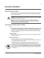
Checking the insulation of the assembly
Drive
Do not make any voltage tolerance or insulation resistance tests (for example, hi-pot
or megger) on any part of the drive as testing can damage the drive. Every drive has
been tested for insulation between the main circuit and the chassis at the factory.
Also, there are voltage-limiting circuits inside the drive which cut down the testing
voltage automatically.
Input power cable
Check the insulation of the input power cable according to local regulations before
connecting to the drive.
Motor and motor cable
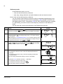
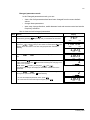
Check the insulation of the motor and motor cable as follows:
1. Check that the motor cable is connected to the motor and disconnected from the
drive output terminals U2, V2 and W2.
ohm
2. Measure the insulation resistance between each phase conductor and the
Protective Earth conductor using a measuring voltage of 500 V DC. The
insulation resistance of an ABB motor must exceed 100 Mohm (reference value
U1
at 25 °C or 77 °F). For the insulation resistance of other motors, please consult
M
V1
3~
the manufacturer’s instructions. Note: Moisture inside the motor casing reduces
W1 PE
the insulation resistance. If moisture is suspected, dry the motor and repeat the
measurement.
Electrical installation
40
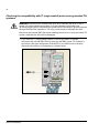
Checking the compatibility with IT (ungrounded) and corner-grounded TN
systems
WARNING! Disconnect the internal EMC filter when installing the drive on an IT
system (an ungrounded power system or a high-resistance-grounded [over
30 ohms] power system), otherwise the system will be connected to ground potential
through the EMC filter capacitors. This may cause danger or damage the drive.
Disconnect the internal EMC filter when installing the drive on a corner-grounded TN
system, otherwise the drive will be damaged.
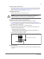
1. If you have an IT (ungrounded) system or corner-grounded TN system,
disconnect the internal EMC filter by removing the EMC screw. For 3-phase Utype drives (with type designation ACS150-03U-), the EMC screw is already
removed at the factory and replaced by a plastic screw.
EMC
VAR
Electrical installation
41
Connecting the power cables
Connection diagram
Drive
INPUT3)
PE
U1
(L)
1)
OUTPUT
V1 W1
(N)
BRK- BRK+
U2
V2
W2
2)
For alternatives, see
section Selecting the
supply disconnecting
device (disconnecting
means) on page 29.
PE
Optional brake
resistor
U1
3
V1
W1
~
Motor
3)
L1
(L)
L2
(N)
L3
1)
Ground the other end of the PE conductor at the distribution board.
2)
Use a separate grounding cable if the conductivity of the cable shield is insufficient (smaller than the conductivity of the
phase conductor) and there is no symmetrically constructed grounding conductor in the cable (see section Selecting the
power cables on page 30).
3)
L and N are connection markings for 1-phase supply.
Note:
Do not use an asymmetrically constructed motor cable.
If there is a symmetrically constructed grounding conductor in the motor cable in addition to the conductive shield, connect
the grounding conductor to the grounding terminal at the drive and motor ends.
For the 1-phase power supply, connect power to U1 (L) and V1 (N) terminals.
Route the motor cable, input power cable and control cables separately. For more information, see section Routing the
cables on page 34.
Grounding of the motor cable shield at the motor end
For minimum radio frequency interference:
• ground the cable by twisting the shield as follows: flattened width > 1/5 · length
b > 1/5 · a
• or ground the cable shield 360 degrees at the lead-through of the motor terminal
box.
a
b
Electrical installation
42
Connection procedure
1. Fasten the input power cable under the grounding clamp. Crimp a cable lug onto
the grounding conductor (PE) of the cable and fasten the lug under a grounding
clamp screw.
2. Connect the phase conductors to the U1, V1 and W1 terminals. Use a tightening
torque of 0.8 N·m (7 lbf·in).
2
1
3. Strip the motor cable and twist the shield to form as short a pigtail as possible.
Fasten the stripped motor cable under the grounding clamp. Crimp a cable lug
onto the pigtail and fasten the lug under a grounding clamp screw.
3
Tightening torque:
0.8 N·m (7 lbf·in)
Electrical installation
43
4. Connect the phase conductors to the U2, V2 and W2 terminals. Use a tightening
torque of 0.8 N·m (7 lbf·in).
5. Connect the optional brake resistor to the BRK+ and BRK- terminals with a
shielded cable using the same procedure as for the motor cable in the previous
step.
6. Secure the cables outside the drive mechanically.
5
4
3
Electrical installation
44
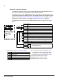
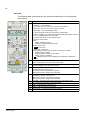
Connecting the control cables
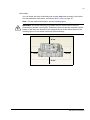
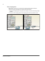
I/O terminals
The figure below shows the I/O terminals.
S1
X1A
X1B
X1A: SCR
X1B: (RO)COM
AI(1)
(RO)NC
GND
(RO)NO
+10 V
+24 V
GND
COM
DI1
DI2
DI3
DI4
DI5 digital or frequency input
The default connection of the control signals depends on the application macro in
use, which is selected with parameter 9902 APPLIC MACRO. See chapter
Application macros on page 69 for the connection diagrams.
Switch S1 selects voltage (0 [2]…10 V) or current (0 [4]…20 mA) as the signal type
for analog input AI. By default, switch S1 is in the current position.
I
Top position: I (0 [4]…20 mA), default for AI
U
Bottom position: U (0 [2]…10 V)
If DI5 is used as a frequency input, set group 18 FREQ INPUT parameters
accordingly.
Electrical installation
45
PNP and NPN configuration for digital inputs
You can wire the digital input terminals in either a PNP or NPN configuration.
PNP connection (source)
X1
+24V
GND
COM
DI1
DI2
DI3
DI4
DI5
NPN connection (sink)
X1
+24V
GND
COM
DI1
DI2
DI3
DI4
DI5
External power supply for digital inputs
For using an external +24 V supply for the digital inputs, see the figure below.
PNP connection (source)
NPN connection (sink)
X1
X1
+24V
+24V
+24
V
DC
0 V DC
GND
GND
COM
COM
+24 V DC
0 V DC
DI1
DI1
DI2
DI2
DI3
DI3
DI4
DI4
DI5
DI5
Electrical installation
46
Default I/O connection diagram
The default connection of the control signals depends on the application macro in
use, which is selected with parameter 9902 APPLIC MACRO.
The default macro is the ABB standard macro. It provides a general purpose I/O
configuration with three constant speeds. Parameter values are the default values
given in section Default parameter values with different macros on page 79. For
information on other macros, see chapter Application macros on page 69.
The default I/O connections for the ABB standard macro are given in the figure
below.
I/O connection 4)
3)
1…10 kohm
Alternative connection
for AI1. If used, switch
IU selector to U
(0…10 V voltage
signal).
SCR
Signal cable shield (screen)
AI
Frequency reference: 0…20 mA
GND
Analog input circuit common
+10V
Reference voltage: +10 V DC, max. 10 mA
+24V
Auxiliary voltage output: +24 V DC, max. 200 mA
GND
Auxiliary voltage output common
COM
Digital input common
DI1
Stop (0) / Start (1)
DI2
Forward (0) / Reverse (1)
DI3
Constant speed selection 1)
DI4
Constant speed selection 1)
DI5
Acceleration and deceleration selection 2)
Relay connection 5)
COM
Relay output
NC
No fault [Fault (-1)]
NO
1) See parameter group 12 CONSTANT SPEEDS:
DI3 DI4 Operation (parameter)
0 0 Set speed through integrated
potentiometer
1 0 Speed 1 (1202 CONST SPEED 1)
0 1 Speed 2 (1203 CONST SPEED 2)
1 1 Speed 3 (1204 CONST SPEED 3)
Electrical installation
2) 0 = ramp times according to parameters 2202
ACCELER TIME 1 and 2203 DECELER TIME 1.
1 = ramp times according to parameters 2205
ACCELER TIME 2 and 2206 DECELER TIME 2.
3) 360 degree grounding under a clamp.
4) Tightening torque: 0.22 N·m / 2 lbf·in
5) Tightening torque: 0.5 N·m / 4.4 lbf·in
47
Connection procedure
1. Analog signal (if connected): Strip the outer insulation of the analog signal cable
360 degrees and ground the bare shield under the clamp.
2. Connect the conductors to the appropriate terminals.
3. Twist the grounding conductors of the used pairs in the analog signal cable
together and connect the bundle to the SCR terminal.
1
2
3
1
Electrical installation
48
4. Digital signals: Strip the outer insulation of the digital signal cable 360 degrees
and ground the bare shield under the clamp.
5. Connect the conductors of the cable to the appropriate terminals.
6. Twist the grounding conductors of the used pairs in the digital signal cable
together and connect the bundle to the SCR terminal.
7. Secure all analog and digital signal cables outside the drive mechanically.
5
6
Tightening torque for:
4
- input signals
0.22 N·m / 2 lbf·in
- relay outputs
0.5 N·m / 4.4 lbf·in
Electrical installation
49
Installation checklist
Checking the installation
Check the mechanical and electrical installation of the drive before start-up. Go
through the checklist below together with another person. Read chapter Safety on
page 11 of this manual before you work on the drive.
Check
MECHANICAL INSTALLATION
The ambient operating conditions are within allowed limits. (See Mechanical installation:
Checking the installation site on page 23 as well as Technical data: Losses, cooling data and
noise on page 142 and Ambient conditions on page 147.)
The drive is fixed properly on an even vertical non-flammable wall. (See Mechanical
installation on page 23.)
The cooling air flows freely. (See Mechanical installation: Free space around the drive on
page 23.)
The motor and the driven equipment are ready for start. (See Planning the electrical
installation: Checking the compatibility of the motor and drive on page 30 as well as Technical
data: Motor connection data on page 144.)
ELECTRICAL INSTALLATION (See Planning the electrical installation on page 29 and Electrical
installation on page 39.)
For ungrounded and corner-grounded systems: The internal EMC filter is disconnected
(screw EMC removed).
The capacitors are reformed if the drive has been stored over a year.
The drive is grounded properly.
The input power voltage matches the drive nominal input voltage.
The input power connections at U1, V1 and W1 are OK and tightened with the correct torque.
Appropriate input power fuses and disconnector are installed.
The motor connections at U2, V2 and W2 are OK and tightened with the correct torque.
The motor cable, input power cable and control cables are routed separately.
The external control (I/O) connections are OK.
The input power voltage cannot be applied to the output of the drive (with a bypass
connection).
Terminal cover and, for NEMA 1, hood and connection box, are in place.
Installation checklist
50
Installation checklist
51
Start-up and control with I/O
What this chapter contains
The chapter instructs how to:
• perform the start-up
• start, stop, change the direction of the motor rotation and adjust the speed of the
motor through the I/O interface.
Using the control panel to do these tasks is explained briefly in this chapter. For
details on how to use the control panel, please refer to chapter Control panel on
page 57.
How to start up the drive
WARNING! The start-up may only be carried out by a qualified
electrician.
The safety instructions given in chapter Safety on page 11 must be followed during
the start-up procedure.
The drive starts up automatically at power-up if the external run command is on and
the drive is in the remote control mode.
Check that the starting of the motor does not cause any danger. De-couple the
driven machine if there is a risk of damage in case of incorrect direction of rotation.
Check the installation. See the checklist in chapter Installation checklist on page 49.
Before you start, ensure that you have the motor nameplate data on hand.
POWER-UP
Apply input power.
The panel powers up into the Output mode.
00
.
LOC
OUTPUT
Hz
FWD
ENTRY OF START-UP DATA
Select the application macro (parameter 9902 APPLIC
MACRO) according to how the control cables are connected.
The default value 1 (ABB STANDARD) is suitable in most cases.
LOC
9902
PAR
s
FWD
The general parameter setting procedure in the Short parameter mode is
described below. You can find more detailed instructions on setting
parameters on page 65.
Start-up and control with I/O
52
The general parameter setting procedure in the Short parameter mode:
LOC
1. To go to the Main menu, press
if the bottom line shows OUTPUT;
otherwise press
repeatedly until you see MENU at the bottom.
/
2. Press keys
until you see “PAr S” on the display.
rEF
MENU
LOC
PAr S
MENU
3. Press
. The display shows a parameter of the Short parameter mode.
LOC
FWD
9902
s
9907
s
PAR
/
4. Find the appropriate parameter with keys
.
LOC
PAR
5. Press and hold
for about two seconds until the parameter value is
shown with SET under the value.
LOC
FWD
FWD
FWD
500
.
Hz
600
.
Hz
PAR SET FWD
6. Change the value with keys
you keep the key pressed down.
/
. The value changes faster while
LOC
PAR SET FWD
7. Save the parameter value by pressing
LOC
.
9907
PAR
Enter the motor data from the motor nameplate:
ABB Motors
3
motor
V
690 Y
400 D
660 Y
380 D
415 D
440 D
Cat. no
M2AA 200 MLA 4
IEC 200 M/L 55
No
Ins.cl. F
IP 55
Hz
kW
r/min
A
cos
IA/IN t E/s
30
32.5 0.83
1475
50
56
50
1475
0.83
30
50
1470
34
0.83
30
30
0.83
1470
59
50
1475
50
54
0.83
30
35 1770
59
0.83
60
3GAA 202 001 - ADA
6312/C3
6210/C3
380 V
supply
voltage
180
IEC 34-1
• motor nominal voltage (parameter 9905 MOTOR NOM
VOLT) – follow steps given above, starting from step 4.
Allowed range: 0.2…2.0 · I2N A
Start-up and control with I/O
FWD
Note: Set the motor data
to exactly the same value
as on the motor
nameplate. Wrong motor
settings of parameter
group 99 may result in
incorrect operation of the
drive.
For example, if the motor
nominal speed is 1440
rpm on the nameplate,
setting the value of
parameter 9908 MOTOR
NOM SPEED to 1500 rpm
results in the wrong
operation of the drive.
LOC
9905
s
9906
s
PAR
• motor nominal current (parameter 9906 MOTOR NOM
CURR)
s
LOC
PAR
FWD
FWD
53
• motor nominal frequency (parameter 9907 MOTOR NOM
FREQ)
LOC
9907
s
1105
s
1202
1203
1204
s
1301
s
2008
s
2102
s
2102
s
PAR
Set the maximum value for external reference REF1
(parameter 1105 REF1 MAX).
LOC
PAR
Set constant speeds (drive output frequencies) 1, 2 and 3
(parameters 1202 CONST SPEED 1, 1203 CONST SPEED 2
and 1204 CONST SPEED 3).
LOC
PAR
LOC
PAR
LOC
PAR
Set the minimum value (%) corresponding to the minimum
signal for AI(1) (parameter 1301 MINIMUM AI1).
LOC
PAR
Set the maximum limit for the drive output frequency
(parameter 2008 MAXIMUM FREQ).
LOC
PAR
Select the motor stop function (parameter 2102 STOP
FUNCTION).
LOC
PAR
FWD
FWD
FWD
s
FWD
s
FWD
FWD
FWD
FWD
DIRECTION OF THE MOTOR ROTATION
Check the direction of the motor rotation.
• Turn the potentiometer fully counterclockwise.
• If the drive is in remote control (REM shown on the left),
switch to local control by pressing LOC
REM .
• Press
to start the motor.
• Turn the potentiometer slightly clockwise until the motor
rotates.
• Check that the actual direction of the motor is the same as
indicated on the display (FWD means forward and REV
reverse).
• Press
to stop the motor.
LOC
PAR
FWD
Start-up and control with I/O
54
To change the direction of the motor rotation:
• Disconnect input power from the drive, and wait 5 minutes
for the intermediate circuit capacitors to discharge. Measure
the voltage between each input terminal (U1, V1 and W1)
and earth with a multimeter to ensure that the drive is
discharged.
• Exchange the position of two motor cable phase conductors
at the drive output terminals or at the motor connection box.
• Verify your work by applying input power and repeating the
check as described above.
forward
direction
reverse
direction
ACCELERATION/DECELERATION TIMES
Set the acceleration time 1 (parameter 2202 ACCELER
TIME 1).
Note: Set also acceleration time 2 (parameter 2205) if two
acceleration times will be used in the application.
LOC
Set the deceleration time 1 (parameter 2203 DECELER
TIME 1).
Note: Set also deceleration time 2 (parameter 2206) if two
deceleration times will be used in the application.
LOC
FINAL CHECK
The start-up is now completed. Check that there are no faults
or alarms shown on the display.
The drive is now ready for use.
Start-up and control with I/O
2202
s
2203
s
PAR
PAR
FWD
FWD
55
How to control the drive through the I/O interface
The table below instructs how to operate the drive through the digital and analog
inputs when:
• the motor start-up is performed, and
• the default (standard) parameter settings are valid.
PRELIMINARY SETTINGS
If you need to change the direction of rotation, check that parameter
1003 DIRECTION is set to 3 (REQUEST).
Ensure that the control connections are wired according to the
connection diagram given for the ABB standard macro.
See Default I/O connection
diagram on page 46.
Ensure that the drive is in remote control. Press key
between remote and local control.
In remote control, the panel
display shows text REM.
LOC
REM
to switch
STARTING AND CONTROLLING THE SPEED OF THE MOTOR
Start by switching digital input DI1 on.
Text FWD starts flashing fast and stops after the setpoint is reached.
REM
OUTPUT
Regulate the drive output frequency (motor speed) by adjusting the
voltage or current of the analog input AI(1).
REM
OUTPUT
00
.
Hz
500
.
Hz
500
.
Hz
500
.
Hz
00
.
Hz
FWD
FWD
CHANGING THE DIRECTION OF THE MOTOR ROTATION
Reverse direction: Switch digital input DI2 on.
REM
OUTPUT
Forward direction: Switch digital input DI2 off.
REM
OUTPUT
REV
FWD
STOPPING THE MOTOR
Switch digital input DI1 off.
The motor stops and text FWD starts flashing slowly.
REM
OUTPUT
FWD
Start-up and control with I/O
56
Start-up and control with I/O
57
Control panel
What this chapter contains
The chapter describes the control panel keys and display fields. It also instructs in
using the panel in control, monitoring and changing the settings.
Integrated control panel
The ACS150 works with an integrated control panel, which provides basic tools for
manual entry of parameter values.
Control panel
58
Overview
The following table summarizes the key functions and displays on the integrated
control panel.
No. Use
1
LCD display – Divided into five areas:
a. Upper left – Control location:
LOC: drive control is local, that is, from the control panel
REM: drive control is remote, such as the drive I/O.
1a
LOC
1d
OUTPUT
1c
1.1
FWD
b. Upper right – Unit of the displayed value.
s: Short parameter mode, browsing the list of parameters.
A 1b
1e
c. Center – Variable; in general, shows parameter and signal values, menus or
lists. Also displays alarm and fault codes.
d. Lower left and center – Panel operation state:
OUTPUT: Output mode
PAR:
Steady: Parameter modes
Flashing: Changed parameters mode
MENU: Main menu.
FAULT : Fault mode.
4
2
3
6
7
8
5
9
10
e. Lower right – Indicators:
FWD (forward) / REV (reverse): direction of the motor rotation
Flashing slowly: stopped
Flashing quickly: running, not at setpoint
Steady: running, at setpoint
SET : Displayed value can be modified (in the Parameter or Reference
mode).
2
RESET/EXIT – Exits to the next higher menu level without saving changed
values. Resets faults in the Output and Fault modes.
3
MENU/ENTER – Enters deeper into menu level. In the Parameter mode,
saves the displayed value as the new setting.
4
Up –
• Scrolls up through a menu or list.
• Increases a value if a parameter is selected.
Holding the key down changes the value faster.
5
Down –
• Scrolls down through a menu or list.
• Decreases a value if a parameter is selected.
Holding the key down changes the value faster.
6
LOC/REM – Changes between local and remote control of the drive.
7
DIR – Changes the direction of the motor rotation.
8
STOP – Stops the drive in local control.
9
START – Starts the drive in local control.
10 Potentiometer – Changes the frequency reference.
Control panel
59
Operation
You can operate the control panel with the help of menus and keys. You can select
an option, for example, an operation mode or a parameter, by scrolling the
and
arrow keys until the option is visible on the display and then pressing the
key.
With the
key, you can return to the previous operation level without saving the
made changes.
The ACS150 includes an integrated potentiometer located at the front of the drive. It
is used for setting the frequency reference.
The integrated control panel has six panel modes: Output mode, Reference mode,
Parameter modes (Short parameter and Long parameter modes), Changed
parameters mode and Fault mode. The operation in the first five modes is described
in this chapter. When a fault or alarm occurs, the panel goes automatically to the
Fault mode showing the fault or alarm code. You can reset the fault or alarm in the
Output or Fault mode (see chapter Fault tracing on page 127).
When the power is switched on, the panel is in the Output mode, where you can
start, stop, change the direction, switch between local and remote control, monitor
up to three actual values (one at a time) and set the frequency reference. To perform
other tasks, go first to the Main menu and select the appropriate mode. The figure
below shows how to move between the modes.
Main menu
LOC
OUTPUT
491
.
Hz
LOC
FWD
rEF
MENU
Output mode (p. 63)
LOC
The panel goes automatically
to the Fault mode.
LOC
FAULT
F0007
PAr S
MENU
FWD
Short parameter mode (p. 65)
LOC
FWD
PAr L
MENU
FWD
Long parameter mode (p. 65)
Fault mode (p. 127)
After reset the panel returns to
the previous display.
FWD
Reference mode (p. 64)
LOC
PArCh
MENU
FWD
Changed parameters mode (p. 65)
Control panel
60
How to perform common tasks
The table below lists common tasks, the mode in which you can perform them and
the page number where the steps of the task are described in detail.
Task
Control panel
Mode
Page
How to switch between local and remote control
Any
61
How to start and stop the drive
Any
61
How to change the direction of the motor rotation
Any
61
How to set the frequency reference
Any
62
How to view and set the frequency reference
Reference
64
How to browse the monitored signals
Output
63
How to change the value of a parameter
Short/Long Parameter
65
How to select the monitored signals
Short/Long Parameter
66
How to view and edit changed parameters
Changed Parameters
67
How to reset faults and alarms
Output, Fault
127
61
How to start, stop and switch between local and remote control
You can start, stop and switch between local and remote control in any mode. To be
able to start or stop the drive, the drive must be in local control.
Step
1.
Action
Display
• To switch between remote control (REM shown on the left) and local
control (LOC shown on the left), press LOC
REM .
LOC
Note: Switching to local control can be disabled with parameter 1606
LOCAL LOCK.
OUTPUT
After pressing the key, the display briefly shows message “LoC” or “rE”,
as appropriate, before returning to the previous display.
LOC
491
.
Hz
FWD
LoC
FWD
The very first time the drive is powered up, it is in remote control (REM) and
controlled through the drive I/O terminals. To switch to local control (LOC)
and control the drive using the control panel and the integrated
potentiometer, press LOC
REM . The result depends on how long you press the
key:
• If you release the key immediately (the display flashes “LoC”), the drive
stops. Set the local control reference with the potentiometer.
• If you press the key for about two seconds (release when the display
changes from “LoC” to “LoC r”), the drive continues as before, except that
the current position of the potentiometer determines the local reference (if
there is a great difference between the remote and local references, the
transfer from remote to local control is not smooth). The drive copies the
current remote value for run/stop status and uses it as the initial local
run/stop setting.
• To stop the drive in local control, press
to stop.
Text FWD or REV on the bottom
line starts flashing slowly.
• To start the drive in local control, press
to start.
Text FWD or REV on the bottom
line starts flashing quickly. It
stops flashing when the drive
reaches the setpoint.
How to change the direction of the motor rotation
You can change the direction of the motor rotation in any mode.
Step
1.
2.
Action
Display
If the drive is in remote control (REM shown on the left), switch to local
control by pressing LOC
REM . The display briefly shows message “LoC” or “rE”,
as appropriate, before returning to the previous display.
LOC
To change the direction from forward (FWD shown at the bottom) to
reverse (REV shown at the bottom), or vice versa, press
.
LOC
OUTPUT
OUTPUT
491
.
Hz
491
.
Hz
FWD
REV
Note: Parameter 1003 DIRECTION must be set to 3 (REQUEST).
Control panel
62
How to set the frequency reference
You can set the local frequency reference with the integrated potentiometer in any
mode when the drive is in local control if parameter 1109 LOC REF SOURCE has
the default value 0 (POT).
If parameter 1109 LOC REF SOURCE has been changed to 1 (KEYPAD), so that
you can use keys
and
for setting the local reference, you have to do it in
the Reference mode (see page 64).
To view the current local reference, you have to go to the Reference mode.
Step
1.
Action
If the drive is in remote control (REM shown on the left), switch to local
control by pressing LOC
REM . The display briefly shows “LoC” before switching
to local control.
Note: With group 11 REFERENCE SELECT, you can allow changing of the
remote (external) reference in remote control (REM) for example, using the
integrated potentiometer or keys
and
.
2.
• To increase the reference value, rotate the integrated potentiometer
clockwise.
• To decrease the reference value, rotate the integrated potentiometer
counterclockwise.
Control panel
Display
LOC
PAr S
MENU
FWD
63
Output mode
In the Output mode, you can:
• monitor actual values of up to three group 01 OPERATING DATA signals, one
signal at a time
• start, stop, change direction, switch between local and remote control and set the
frequency reference.
You can transfer to the Output mode by pressing the
text OUTPUT at the bottom.
The display shows the value of one group 01
OPERATING DATA signal. The unit is shown on the
right. Page 66 tells how to select up to three signals to
be monitored in the Output mode. The table below
shows how to view them one at a time.
key until the display shows
REM
OUTPUT
491
.
Hz
FWD
How to browse the monitored signals
Step
1.
Action
Display
If more than one signals have been selected to be monitored (see page
66), you can browse them in the Output mode.
To browse the signals forward, press key
them backward, press key
repeatedly.
repeatedly. To browse
REM
OUTPUT
REM
OUTPUT
REM
OUTPUT
491
.
05
.
107
.
Hz
FWD
A
FWD
%
FWD
Control panel
64
Reference mode
In the Reference mode, you can:
• view and set the frequency reference
• start, stop, change direction and switch between local and remote control.
How to view and set the frequency reference
You can set the local frequency reference with the integrated potentiometer in any
mode when the drive is in local control if parameter 1109 LOC REF SOURCE has
the default value 0 (POT). If parameter 1109 LOC REF SOURCE has been changed
to 1 (KEYPAD), you have to set the local frequency reference in the Reference
mode.
You can view the current local reference in the Reference mode only.
Step
1.
Action
Display
Go to the Main menu by pressing
if you are in the Output mode,
otherwise by pressing
repeatedly until you see MENU at the bottom.
REM
PAr S
MENU
2.
If the drive is in remote control (REM shown on the left), switch to local
control by pressing LOC
REM . The display briefly shows “LoC” before switching
to local control.
LOC
FWD
PAr S
MENU
FWD
Note: With group 11 REFERENCE SELECT, you can allow changing of the
remote (external) reference in remote control (REM) for example, using the
integrated potentiometer or keys
and
.
3.
If the panel is not in the Reference mode (“rEF” not visible), press key
or
until you see “rEF” and then press
. Now the display
shows the current reference value with SET under the value.
LOC
rEF
491
.
MENU
LOC
FWD
Hz
SET FWD
4.
If parameter 1109 LOC REF SOURCE = 0 (POT, default):
• To increase the reference value, rotate the integrated potentiometer
clockwise.
• To decrease the reference value, rotate the integrated potentiometer
counterclockwise.
LOC
The new value (potentiometer setting) is shown on the display.
500
.
Hz
500
.
Hz
SET FWD
If parameter 1109 LOC REF SOURCE = 1 (KEYPAD):
• To increase the reference value, press
• To decrease the reference value, press
The new value is shown on the display.
Control panel
.
.
LOC
SET FWD
65
Parameter modes
There are two parameter modes: Short parameter mode and Long parameter mode.
Both function identically, except that the Short parameter mode shows only the
minimum number of parameters typically required to set up the drive (see section
Parameters in the Short parameter mode on page 80). The Long parameter mode
shows all user parameters including those shown in the Short parameter mode.
In the Parameter modes, you can:
• view and change parameter values
• start, stop, change direction, switch between local and remote control and set the
frequency reference.
How to select a parameter and change its value
Step
1.
Action
Display
Go to the Main menu by pressing
if you are in the Output mode,
otherwise by pressing
repeatedly until you see MENU at the bottom.
LOC
rEF
MENU
2.
If the panel is not in the desired Parameter mode (“PAr S”/“PAr L” not
visible), press key
or
until you see “PAr S” (Short parameter
mode) or “PAr L” (Long parameter mode), as appropriate.
LOC
LOC
3.
Short parameter mode (PAr S):
LOC
• Press
. The display shows one of the parameters of the Short
parameter mode. Letter s in the top right corner indicates that you are
browsing parameters in the Short parameter mode.
Long parameter mode (PAr L):
• Use keys
• Press
group.
and
to find the desired parameter group.
LOC
LOC
. The display shows one of the parameters in the selected
LOC
4.
Use keys
and
to find the desired parameter.
PAr S
PAr L
MENU
FWD
MENU
FWD
1202
PAR
• Press
. The display shows the number of one of the parameter
groups in the Long parameter mode.
LOC
Press and hold
for about two seconds until the display shows the
value of the parameter with SET underneath indicating that changing of the
value is now possible.
LOC
s
FWD
-01-121202
PAR
FWD
PAR
FWD
PAR
FWD
1203
PAR
5.
FWD
FWD
100
.
Hz
PAR SET FWD
Note: When SET is visible, pressing keys
and
simultaneously changes the displayed value to the default value of the
parameter.
Control panel
66
Step
6.
Action
Display
Use keys
and
to select the parameter value. When you have
changed the parameter value, SET starts flashing.
LOC
120
.
1203
Hz
PAR SET FWD
• To save the displayed parameter value, press
.
• To cancel the new value and keep the original, press
LOC
.
PAR
FWD
How to select the monitored signals
Step
1.
Action
Display
You can select which signals are monitored in the Output mode and how
they are displayed with group 34 PANEL DISPLAY parameters. See page
65 for detailed instructions on changing parameter values.
LOC
By default, the display shows: 0103 OUTPUT FREQ, 0104 CURRENT and
0105 TORQUE.
LOC
To change the default signals, select from group 01 OPERATING DATA up
to three signals to be browsed.
103
104
105
PAR SET FWD
PAR SET FWD
LOC
Signal 1: Change the value of parameter 3401 SIGNAL1 PARAM to the
index of the signal parameter in group 01 OPERATING DATA (= number of
the parameter without the leading zero), for example, 105 means
parameter 0105 TORQUE. Value 0 means that no signal is displayed.
PAR SET FWD
Repeat for signals 2 (3408 SIGNAL2 PARAM) and 3 (3415 SIGNAL3
PARAM). For example, if 3401 SIGNAL1 PARAM = 0 and 3415 SIGNAL3
PARAM = 0, browsing is disabled and only the signal specified by 3408
SIGNAL2 PARAM appears on the display. If all three parameters are set to
0, that is no signals are selected for monitoring, the panel displays text
“n.A.”.
2.
Specify the decimal point location, or use the decimal point location and
unit of the source signal (setting 9 [DIRECT]). For details, see parameter
3404 OUTPUT1 DSP FORM.
LOC
9
PAR SET FWD
Signal 1: parameter 3404 OUTPUT1 DSP FORM
Signal 2: parameter 3411 OUTPUT2 DSP FORM
Signal 3: parameter 3418 OUTPUT3 DSP FORM.
3.
Select the units to be displayed for the signals. This has no effect if
parameter 3404/3411/3418 is set to 9 (DIRECT). For details, see
parameter 3405 OUTPUT1 UNIT.
LOC
3
PAR SET FWD
Signal 1: parameter 3405 OUTPUT1 UNIT
Signal 2: parameter 3412 OUTPUT2 UNIT
Signal 3: parameter 3419 OUTPUT3 UNIT.
4.
Select the scalings for the signals by specifying the minimum and
maximum display values. This has no effect if parameter 3404/3411/3418 is
set to 9 (DIRECT). For details, see parameters 3406 OUTPUT1 MIN and
3407 OUTPUT1 MAX.
Signal 1: parameters 3406 OUTPUT1 MIN and 3407 OUTPUT1 MAX
Signal 2: parameters 3413 OUTPUT2 MIN and 3414 OUTPUT2 MAX
Signal 3: parameters 3420 OUTPUT3 MIN and 3421 OUTPUT3 MAX.
Control panel
LOC
00
.
5000
.
Hz
PAR SET FWD
LOC
PAR SET FWD
Hz
67
Changed parameters mode
In the Changed parameters mode, you can:
• view a list of all parameters that have been changed from the macro default
values
• change these parameters
• start, stop, change direction, switch between local and remote control and set the
frequency reference.
How to view and edit changed parameters
Step
1.
Action
Display
Go to the Main menu by pressing
if you are in the Output mode,
otherwise by pressing
repeatedly until you see MENU at the bottom.
LOC
rEF
MENU
2.
If the panel is not in the Changed parameters mode (“PArCh” not visible),
press key
or
until you see “PArCh” and then press
. The
display shows the number of the first changed parameter and PAR is
flashing.
LOC
PArCh
1103
MENU
LOC
FWD
PAR
3.
Use keys
list.
and
to find the desired changed parameter on the
LOC
Press and hold
for about two seconds until the display shows the
value of the parameter with SET underneath indicating that changing of the
value is now possible.
FWD
1003
PAR
4.
FWD
FWD
1
LOC
PAR SET FWD
Note: When SET is visible, pressing keys
and
simultaneously changes the displayed value to the default value of the
parameter.
5.
Use keys
and
to select the parameter value. When you have
changed the parameter value, SET starts flashing.
LOC
2
1003
PAR SET FWD
• To save the displayed parameter value, press
.
• To cancel the new value and keep the original, press
LOC
.
PAR
FWD
Control panel
68
Control panel
69
Application macros
What this chapter contains
The chapter describes the application macros. For each macro, there is a wiring
diagram showing the default control connections (digital and analog I/O). The
chapter also explains how to save a user macro and how to recall it.
Overview of macros
Application macros are pre-programmed parameter sets. While starting up the drive,
the user selects the macro best suited for the purpose with parameter 9902 APPLIC
MACRO, makes the essential changes and saves the result as a user macro.
The ACS150 has six standard macros and three user macros. The table below
contains a summary of the macros and describes suitable applications.
Macro
Suitable applications
ABB standard
Ordinary speed control applications where no, one, two or three constant speeds
are used. Start/stop is controlled with one digital input (level start and stop). It is
possible to switch between two acceleration and deceleration times.
3-wire
Ordinary speed control applications where no, one, two or three constant speeds
are used. The drive is started and stopped with push buttons.
Alternate
Speed control applications where no, one, two or three constant speeds are used.
Start, stop and direction are controlled by two digital inputs (combination of the
input states determines the operation).
Motor
potentiometer
Speed control applications where no or one constant speed is used. The speed is
controlled by two digital inputs (increase / decrease / keep unchanged).
Hand/Auto
Speed control applications where switching between two control devices is
needed. Some control signal terminals are reserved for one device, the rest for
the other. One digital input selects between the terminals (devices) in use.
PID control
Process control applications, for example, different closed loop control systems
such as pressure control, level control and flow control. It is possible to switch
between process and speed control: Some control signal terminals are reserved
for process control, others for speed control. One digital input selects between
process and speed control.
User
The user can save the customised standard macro, that is the parameter settings,
including group 99 START-UP DATA, into the permanent memory, and recall the
data at a later time.
For example, three user macros can be used when switching between three
different motors is required.
Application macros
70
Summary of I/O connections of application macros
The following table gives the summary of the default I/O connections of all
application macros.
Macro
Input/output
ABB standard
3-wire
Alternate
Motor
potentiometer
Hand/Auto
PID control
AI
Frequency
reference
Frequency
reference
Frequency
reference
-
Frequency ref.
(Auto) 1)
Freq. ref.
(Hand) / Proc.
ref. (PID)
DI1
Stop/Start
Start (pulse)
Start (forward)
Stop/Start
Stop/Start
(Hand)
Stop/Start
(Hand)
DI2
Forward/
Reverse
Stop (pulse)
Start (reverse)
Forward/
Reverse
Forward/
Hand/PID
Reverse (Hand)
DI3
Constant speed Forward/
input 1
Reverse
DI4
Constant speed Constant speed Constant speed Frequency
Forward/
Run enable
input 2
input 1
input 2
reference down Reverse (Auto)
DI5
Ramp pair
selection
RO
Fault (-1)
(COM, NC, NO)
1)
Application macros
Constant speed Frequency
input 1
reference up
Hand/Auto
Constant
speed 1
Constant speed Ramp pair
input 2
selection
Constant
speed 1
Stop/Start
(Auto)
Stop/Start (PID)
Fault (-1)
Fault (-1)
Fault (-1)
Fault (-1)
Fault (-1)
The frequency reference comes from the integrated potentiometer when Hand is selected.
71
ABB standard macro
This is the default macro. It provides a general purpose I/O configuration with three
constant speeds. Parameter values are the default values given in chapter Actual
signals and parameters, starting from page 79.
If you use other than the default connections presented below, see section I/O
terminals on page 44.
Default I/O connections
I/O connection 4)
3)
1…10 kohm
Alternative connection
for AI1. If used, switch
IU selector to U
(0…10 V voltage
signal).
SCR
Signal cable shield (screen)
AI
Frequency reference: 0…20 mA
GND
Analog input circuit common
+10V
Reference voltage: +10 V DC, max. 10 mA
+24V
Auxiliary voltage output: +24 V DC, max. 200 mA
GND
Auxiliary voltage output common
COM
Digital input common
DI1
Stop (0) / Start (1)
DI2
Forward (0) / Reverse (1)
DI3
Constant speed selection 1)
DI4
Constant speed selection 1)
DI5
Acceleration and deceleration selection 2)
Relay connection 5)
COM
Relay output
NC
No fault [Fault (-1)]
NO
1)
See parameter group 12 CONSTANT SPEEDS:
DI3 DI4 Operation (parameter)
0 0 Set speed through integrated
potentiometer
1 0 Speed 1 (1202 CONST SPEED 1)
0 1 Speed 2 (1203 CONST SPEED 2)
1 1 Speed 3 (1204 CONST SPEED 3)
2)
0 = ramp times according to parameters 2202
ACCELER TIME 1 and 2203 DECELER TIME 1.
1 = ramp times according to parameters 2205
ACCELER TIME 2 and 2206 DECELER TIME 2.
3)
360 degree grounding under a clamp.
4)
Tightening torque: 0.22 N·m / 2 lbf·in
5)
Tightening torque: 0.5 N·m / 4.4 lbf·in
Application macros
72
3-wire macro
This macro is used when the drive is controlled using momentary push-buttons. It
provides three constant speeds. To enable the macro, set the value of parameter
9902 APPLIC MACRO to 2 (3-WIRE).
For the parameter default values, see section Default parameter values with different
macros on page 79. If you use other than the default connections presented below,
see section I/O terminals on page 44.
Note: When the stop input (DI2) is deactivated (no input), the control panel start and
stop buttons are disabled.
Default I/O connections
I/O connection 3)
SCR
2)
1…10 kohm
Alternative connection
for AI1. If used, switch
IU selector to U
(0…10 V voltage
signal).
Signal cable shield (screen)
AI
Frequency reference: 0…20 mA
GND
Analog input circuit common
+10V
Reference voltage: +10 V DC, max. 10 mA
+24V
Auxiliary voltage output: +24 V DC, max. 200 mA
GND
Auxiliary voltage output common
COM
Digital input common
DI1
Start (pulse
)
DI2
Stop (pulse
)
DI3
Forward (0) / Reverse (1)
DI4
Constant speed selection 1)
DI5
Constant speed selection 1)
Relay connection 4)
COM
Relay output
NC
No fault [Fault (-1)]
NO
1)
See parameter group 12 CONSTANT SPEEDS:
DI3 DI4 Operation (parameter)
0 0 Set speed through integrated
potentiometer
1 0 Speed 1 (1202 CONST SPEED 1)
0 1 Speed 2 (1203 CONST SPEED 2)
1 1 Speed 3 (1204 CONST SPEED 3)
Application macros
2)
360 degree grounding under a clamp.
3)
Tightening torque: 0.22 N·m / 2 lbf·in
4)
Tightening torque: 0.5 N·m / 4.4 lbf·in
73
Alternate macro
This macro provides an I/O configuration adapted to a sequence of DI control
signals used when alternating the rotation direction of the drive. To enable the
macro, set the value of parameter 9902 APPLIC MACRO to 3 (ALTERNATE).
For the parameter default values, see section Default parameter values with different
macros on page 79. If you use other than the default connections presented below,
see section I/O terminals on page 44.
Default I/O connections
I/O connection 4)
SCR
3)
1…10 kohm
Alternative connection
for AI1. If used, switch
IU selector to U
(0…10 V voltage
signal).
Signal cable shield (screen)
AI
Frequency reference: 0…20 mA
GND
Analog input circuit common
+10V
Reference voltage: +10 V DC, max. 10 mA
+24V
Auxiliary voltage output: +24 V DC, max. 200 mA
GND
Auxiliary voltage output common
COM
Digital input common
DI1
Start forward: If DI1 = DI2, the drive stops.
DI2
Start reverse
DI3
Constant speed selection 1)
DI4
Constant speed selection 1)
DI5
Acceleration and deceleration selection 2)
Relay connection 5)
COM
Relay output
NC
No fault [Fault (-1)]
NO
1)
See parameter group 12 CONSTANT SPEEDS: 2) 0 = ramp times according to parameters 2202
ACCELER TIME 1 and 2203 DECELER
DI3 DI4 Operation (parameter)
TIME 1.
0 0 Set speed through integrated
1 = ramp times according to parameters 2205
potentiometer
ACCELER TIME 2 and 2206 DECELER
1 0 Speed 1 (1202 CONST SPEED 1)
TIME 2.
0 1 Speed 2 (1203 CONST SPEED 2)
3) 360 degree grounding under a clamp.
1 1 Speed 3 (1204 CONST SPEED 3)
4) Tightening torque: 0.22 N·m / 2 lbf·in
5)
Tightening torque: 0.5 N·m / 4.4 lbf·in
Application macros
74
Motor potentiometer macro
This macro provides a cost-effective interface for PLCs that vary the speed of the
drive using only digital signals. To enable the macro, set the value of parameter 9902
APPLIC MACRO to 4 (MOTOR POT).
For the parameter default values, see section Default parameter values with different
macros on page 79. If you use other than the default connections presented below,
see section I/O terminals on page 44.
Default I/O connections
I/O connection 2)
SCR
Signal cable shield (screen)
AI
Not in use by default: 0…20 mA
GND
Analog input circuit common
+10V
Reference voltage: +10 V DC, max. 10 mA
+24V
Auxiliary voltage output: +24 V DC, max. 200 mA
GND
Auxiliary voltage output common
COM
Digital input common
DI1
Stop (0) / Start (1)
DI2
Forward (0) / Reverse (1)
DI3
Frequency reference up 1)
DI4
Frequency reference down 1)
DI5
Constant speed 1: parameter 1202 CONST SPEED 1
Relay connection 3)
COM
Relay output
NC
No fault [Fault (-1)]
NO
1)
If DI3 and DI4 are both active or inactive, the
frequency reference is unchanged.
The existing frequency reference is stored
during stop and power down.
Application macros
2)
Tightening torque: 0.22 N·m / 2 lbf·in
3)
Tightening torque: 0.5 N·m / 4.4 lbf·in
75
Hand/Auto macro
This macro can be used when switching between two external control devices is
needed. To enable the macro, set the value of parameter 9902 APPLIC MACRO to
5 (HAND/AUTO).
For the parameter default values, see section Default parameter values with different
macros on page 79. If you use other than the default connections presented below,
see section I/O terminals on page 44.
Note: Parameter 2108 START INHIBIT must remain in the default setting 0 (OFF).
Default I/O connections
I/O connection 3)
2)
1…10 kohm
Alternative connection
for AI1. If used, switch
IU selector to U
(2…10 V voltage
signal).
SCR
Signal cable shield (screen)
AI
Frequency reference (Auto): 4…20 mA 1)
GND
Analog input circuit common
+10V
Reference voltage: +10 V DC, max. 10 mA
+24V
Auxiliary voltage output: +24 V DC, max. 200 mA
GND
Auxiliary voltage output common
COM
Digital input common
DI1
Stop (0) / Start (1) (Hand)
DI2
Forward (0) / Reverse (1) (Hand)
DI3
Hand (0) / Auto (1) control selection
DI4
Forward (0) / Reverse (1) (Auto)
DI5
Stop (0) / Start (1) (Auto)
Relay connection 4)
COM
Relay output
NC
No fault [Fault (-1)]
NO
1)
2)
In the Hand mode, the frequency reference
comes from the integrated potentiometer.
3)
Tightening torque: 0.22 N·m / 2 lbf·in
4)
Tightening torque: 0.5 N·m / 4.4 lbf·in
360 degree grounding under a clamp.
Application macros
76
PID control macro
This macro provides parameter settings for closed-loop control systems such as
pressure control, flow control, and so on. Control can also be switched to speed
control using a digital input. To enable the macro, set the value of parameter 9902
APPLIC MACRO to 6 (PID CONTROL).
For the parameter default values, see section Default parameter values with different
macros on page 79. If you use other than the default connections presented below,
see chapter Electrical installation, section I/O terminals on page 44.
Note: Parameter 2108 START INHIBIT must remain in the default setting 0 (OFF).
Default I/O connections
I/O connection 3)
2)
1…10 kohm
Alternative connection
for AI1. If used, switch
IU selector to U
(2…10 V voltage
signal).
SCR
Signal cable shield (screen)
AI
Process actual value: 4…20 mA 1)
GND
Analog input circuit common
+10V
Reference voltage: +10 V DC, max. 10 mA
+24V
Auxiliary voltage output: +24 V DC, max. 200 mA
GND
Auxiliary voltage output common
COM
Digital input common
DI1
Stop (0) / Start (1) (Hand)
DI2
Hand (0) / PID (1) control selection
DI3
Constant speed 1: parameter 1202 CONST SPEED 1
DI4
Run enable
DI5
Stop (0) / Start (1) (PID)
Relay connection 4)
COM
Relay output
NC
No fault [Fault (-1)]
NO
1)
Application macros
Hand: frequency reference comes from the
integrated potentiometer
PID: Process reference comes from the
integrated potentiometer.
2)
360 degree grounding under a clamp.
3)
Tightening torque: 0.22 N·m / 2 lbf·in
4)
Tightening torque: 0.5 N·m / 4.4 lbf·in
77
User macros
In addition to the standard application macros, it is possible to create three user
macros. The user macro allows the user to save the parameter settings, including
group 99 START-UP DATA, into the permanent memory and recall the data at a later
time. The panel reference is also saved if the macro is saved and loaded in local
control. The remote control setting is saved into the user macro, but the local control
setting is not.
The steps below show how to create and recall User macro 1. The procedure for the
other two user macros is identical, only the parameter 9902 APPLIC MACRO values
are different.
To create User macro 1:
• Adjust the parameters.
• Save the parameter settings to the permanent memory by changing parameter
9902 APPLIC MACRO to -1 (USER S1 SAVE).
• Press
MENU
ENTER
to save.
To recall User macro 1:
• Change parameter 9902 APPLIC MACRO to 0 (USER S1 LOAD).
• Press
MENU
ENTER
to load.
Note: User macro load restores the parameter settings including group 99 STARTUP DATA. Check that the settings correspond to the motor used.
Hint: The user can for example switch the drive between three motors without
having to adjust the motor parameters every time the motor is changed. The user
needs only to adjust the settings once for each motor and then to save the data as
three user macros. When the motor is changed, only the corresponding user macro
needs to be loaded, and the drive is ready to operate.
Application macros
78
Application macros
79
Actual signals and parameters
What this chapter contains
The chapter describes the actual signals and parameters. It also contains a table of
the default values for the different macros.
Terms and abbreviations
Term
Definition
Actual signal
Signal measured or calculated by the drive. Can be monitored by the user.
No user setting possible. Groups 01...04 contain actual signals.
Def
Parameter default value
Parameter
A user-adjustable operation instruction of the drive. Groups 10...99 contain
parameters.
E
Refers to types 01E- and 03E- with European parametrization
U
Refers to types 01U- and 03U- with US parametrization
Default parameter values with different macros
When application macro is changed (9902 APPLIC MACRO), the software updates
the parameter values to their default values. The following table includes the
parameter default values for different macros. For other parameters, the default
values are the same for all macros (see section Actual signals on page 84).
Index Name/
Selection
1001 EXT1
COMMANDS
1002 EXT2
COMMANDS
1003 DIRECTION
1102 EXT1/EXT2
SEL
1103 REF1 SELECT
1 = AI1
1 = AI1
1 = AI1
1106
1201
2 = POT
9 = DI3,4
2 = POT
10 = DI4,5
0.0%
0 = NOT SEL
5 = DI5
1 = ABB
STANDARD
1301
1601
2201
9902
REF2 SELECT
CONST
SPEED SEL
MINIMUM AI1
RUN ENABLE
ACC/DEC 1/2
SEL
APPLIC
MACRO
ABB
STANDARD
2 = DI1,2
3-WIRE
ALTERNATE
MOTOR POT
HAND/AUTO
PID CONTROL
4 = DI1P,2P,3
9 = DI1F,2R
2 = DI1,2
2 = DI1,2
1 = DI1
0 = NOT SEL
0 = NOT SEL
0 = NOT SEL
0 = NOT SEL
21 = DI5,4
20 = DI5
3 = REQUEST 3 = REQUEST 3 = REQUEST 3 = REQUEST 3 = REQUEST 1 = FORWARD
0 = EXT1
0 = EXT1
0 = EXT1
0 = EXT1
3 = DI3
2 = DI2
1 = AI1
2 = POT
2 = POT
9 = DI3,4
12 =
DI3U,4D(NC)
1 = AI1
5 = DI5
2 = POT
0 = NOT SEL
19 = PID1OUT
3 = DI3
0.0%
0 = NOT SEL
0 = NOT SEL
0.0%
0 = NOT SEL
5 = DI5
0.0%
0 = NOT SEL
0 = NOT SEL
20.0%
0 = NOT SEL
0 = NOT SEL
20.0%
4 = DI4
0 = NOT SEL
2 = 3-WIRE
3=
ALTERNATE
4 = MOTOR
POT
5 = HAND/
AUTO
6 = PID
CONTROL
Actual signals and parameters
80
Parameters in the Short parameter mode
The following table describes the parameters that are visible in the Short parameter
mode. See section Parameter modes on page 65 for how to select the parameter
mode. All parameters are presented in detail in section Parameters in the Long
parameter mode, starting on page 86.
Parameters in the Short parameter mode
No.
Name/Value
Description
Def
99 START-UP DATA
Application macro. Definition of motor set-up data.
9902
APPLIC MACRO
Selects the application macro or activates FlashDrop parameter values. See 1 = ABB
chapter Application macros on page 69.
STANDARD
1 = ABB STANDARD
Standard macro for constant speed applications
2 = 3-WIRE
3-wire macro for constant speed applications
3 = ALTERNATE
Alternate macro for start forward and start reverse applications
4 = MOTOR POT
Motor potentiometer macro for digital signal speed control applications
5 = HAND/AUTO
Hand/Auto macro to be used when two control devices are connected to the
drive:
- Device 1 communicates through the interface defined by external control
location EXT1.
- Device 2 communicates through the interface defined by external control
location EXT2.
EXT1 or EXT2 is active at a time. Switching between EXT1/2 through digital
input.
6 = PID CONTROL
PID control. For applications in which the drive controls a process value. For
example, pressure control by the drive running the pressure boost pump.
Measured pressure and the pressure reference are connected to the drive.
31 = LOAD FD SET
FlashDrop parameter values as defined by the FlashDrop file.
FlashDrop is an optional device for fast copying of parameters to unpowered
drives. FlashDrop allows easy customisation of the parameter list, for
example, selected parameters can be hidden. For more information, see
MFDT-01 FlashDrop user’s manual (3AFE68591074 [English]).
0 = USER S1 LOAD
User 1 macro loaded into use. Before loading, check that the saved
parameter settings and the motor model are suitable for the application.
-1 = USER S1 SAVE
Save User 1 macro. Stores the current parameter settings and the motor
model.
-2 = USER S2 LOAD
User 2 macro loaded into use. Before loading, check that the saved
parameter settings and the motor model are suitable for the application.
-3 = USER S2 SAVE
Save User 2 macro. Stores the current parameter settings and the motor
model.
-4 = USER S3 LOAD
User 3 macro loaded into use. Before loading, check that the saved
parameter settings and the motor model are suitable for the application.
-5 = USER S3 SAVE
Save User 3 macro. Stores the current parameter settings and the motor
model.
Actual signals and parameters
81
Parameters in the Short parameter mode
No.
Name/Value
Description
Def
9905
MOTOR NOM VOLT
Defines the nominal motor voltage. Must be equal to the value on the motor
rating plate. The drive cannot supply the motor with a voltage greater than
the input power voltage.
200 V
E units:
200 V
Note that the output voltage is not limited by the nominal motor voltage but
increased linearly up to the value of the input voltage
Output voltage
230 V
U units:
230 V
Input voltage
9905
Output frequency
400 V
E units:
400 V
9907
WARNING! Never connect a motor to a drive which is connected to power
line with voltage level higher than the rated motor voltage.
200 V E units/
230 U units:
100...300 V
460 V
U units:
460 V
Voltage.
Note: The stress on the motor insulations is always dependent on the drive
supply voltage. This also applies to the case where the motor voltage rating
is lower than the rating of the drive and the supply of the drive.
400 V E units /
460 V U units:
230...690 V
9906
9907
MOTOR NOM CURR
Defines the nominal motor current. Must be equal to the value on the motor
rating plate.
0.2…2.0 · I2N
Current
MOTOR NOM FREQ
Defines the nominal motor frequency, that is the frequency at which the
output voltage equals the motor nominal voltage:
10.0…500.0 Hz
Frequency
I2N
E: 50 / U: 60
Field weakening point = Nom. frequency · Supply voltage / Mot nom. voltage
04 FAULT HISTORY
Fault history (read-only)
0401
Fault code of the latest fault. See chapter Fault tracing on page 127 for the
codes. 0 = fault history is clear (on panel display = NO RECORD).
LAST FAULT
11 REFERENCE
SELECT
Maximum reference
1105
Defines the maximum value for external reference REF1. Corresponds to
maximum mA/(V) signal for analog input AI1.
REF1 MAX
-
E: 50.0 Hz /
U: 60.0 Hz
REF (Hz)
1105
(MAX)
0
0.0…500.0 Hz
1301
100%
(20 mA / 10 V)
AI1 signal (%)
Maximum value
Actual signals and parameters
82
Parameters in the Short parameter mode
No.
Name/Value
Description
Def
12 CONSTANT SPEEDS Constant speeds. Constant speed activation overrides the external speed
reference. Constant speed selections are ignored if drive is in the local
control mode.
As default constant speed selection is made through digital inputs DI3 and
DI4.1 = DI active, 0 = DI inactive.
DI3 DI4 Operation
0
0 No constant speed
1
0 Speed defined by parameter 1202 CONST SPEED 1
0
1 Speed defined by parameter 1203 CONST SPEED 2
1
1 Speed defined by parameter 1204 CONST SPEED 3
1202
CONST SPEED 1
Defines constant speed 1 (that is drive output frequency).
E: 5.0 Hz /
U: 6.0 Hz
1203
1204
0.0…500.0 Hz
Output frequency
CONST SPEED 2
Defines constant speed 2 (that is drive output frequency).
0.0…500.0 Hz
Output frequency
CONST SPEED 3
Defines constant speed 3 (that is drive output frequency).
0.0…500.0 Hz
Output frequency
E: 10.0 Hz /
U: 12.0 Hz
E: 15.0 Hz /
U: 18.0 Hz
13 ANALOG INPUTS
Analog input signal minimum
1301
Defines the minimum % value that corresponds to minimum mA/(V) signal for 0%
analog input AI1.
MINIMUM AI1
0...20 mA = 0...100%
4...20 mA = 20...100%
When analog input AI1 is selected as the source for external reference
REF1, the value corresponds to the minimum reference value, that is 0 Hz.
See the figure for parameter 1105 REF1 MAX.
0…100.0%
Value in percent of the full signal range. Example: If the minimum value for
analog input is 4 mA, the percent value for 0…20 mA range is:
(4 mA / 20 mA) · 100% = 20%
20 LIMITS
Maximum frequency
2008
Defines the maximum limit for the drive output frequency.
f
MAXIMUM FREQ
E: 50.0 Hz /
U: 60.0 Hz
2008
Allowed frequency range
0
t
-(2008)
0.0…500.0 Hz
Maximum frequency
21 START/STOP
Stop mode of the motor
2102
STOP FUNCTION
Selects the motor stop function.
1 = COAST
Stop by cutting off the motor power supply. The motor coasts to stop.
2 = RAMP
Stop along a linear ramp. See parameter group 22 ACCEL/DECEL.
Actual signals and parameters
1 = COAST
83
Parameters in the Short parameter mode
No.
Name/Value
Description
Def
22 ACCEL/DECEL
Acceleration and deceleration times
2202
Defines the acceleration time 1, that is the time required for the speed to
5.0 s
change from zero to the speed defined by parameter 2008 MAXIMUM FREQ.
ACCELER TIME 1
- If the speed reference increases faster than the set acceleration rate, the
motor speed follows the acceleration rate.
- If the speed reference increases slower than the set acceleration rate, the
motor speed follows the reference signal.
- If the acceleration time is set too short, the drive automatically prolongs the
acceleration in order not to exceed the drive operating limits.
2203
0.0…1800.0 s
Time
DECELER TIME 1
Defines the deceleration time 1, that is the time required for the speed to
5.0 s
change from the value defined by parameter 2008 MAXIMUM FREQ to zero.
- If the speed reference decreases slower than the set deceleration rate, the
motor speed follows the reference signal.
- If the reference changes faster than the set deceleration rate, the motor
speed follows the deceleration rate.
- If the deceleration time is set too short, the drive automatically prolongs the
deceleration in order not to exceed drive operating limits.
If a short deceleration time is needed for a high inertia application, the drive
should be equipped a brake resistor.
0.0…1800.0 s
Time
Actual signals and parameters
84
Actual signals
The following table includes the descriptions of all actual signal.
Actual signals
No.
Name/Value
01 OPERATING DATA
Description
Basic signals for monitoring the drive (read-only).
For actual signal supervision, see parameter group 32 SUPERVISION.
For selection of an actual signal to be displayed on the control panel, see parameter
group 34 PANEL DISPLAY.
0101
SPEED & DIR
Calculated motor speed in rpm. A negative value indicates reverse direction.
0102
SPEED
Calculated motor speed in rpm.
0103
OUTPUT FREQ
Calculated drive output frequency in Hz. (Shown by default on the panel Output mode
display.)
0104
CURRENT
Measured motor current in A
0105
TORQUE
Calculated motor torque in percent of the motor nominal torque
0106
POWER
Measured motor power in kW
0107
DC BUS VOLTAGE
Measured intermediate circuit voltage in V DC
0109
OUTPUT VOLTAGE
Calculated motor voltage in V AC
0110
DRIVE TEMP
Measured IGBT temperature in °C
0111
EXTERNAL REF 1
External reference REF1 in Hz
0112
EXTERNAL REF 2
External reference REF2 in percent. 100% equals the maximum motor speed.
0113
CTRL LOCATION
Active control location. (0) LOCAL; (1) EXT1; (2) EXT2.
0114
RUN TIME (R)
Elapsed drive running time counter (hours). Runs when the drive is modulating. The
counter can be reset by pressing the UP and DOWN keys simultaneously when the
control panel is in the Parameter mode.
0115
KWH COUNTER (R)
kWh counter. The counter value is accumulated till it reaches 65535 after which the
counter rolls over and starts again from 0. The counter can be reset by pressing UP and
DOWN keys simultaneously when the control panel is in the Parameter mode.
0120
AI 1
Relative value of analog input AI1 in percent
0121
POT
Potentiometer value in percent
0126
PID 1 OUTPUT
Output value of the process PID1 controller in percent
0128
PID 1 SETPNT
Setpoint signal (reference) for the process PID1 controller. Unit depends on parameter
4006 UNITS and 4007 UNIT SCALE settings.
0130
PID 1 FBK
Feedback signal for the process PID1 controller. Unit depends on parameter 4006 UNITS
and 4007 UNIT SCALE settings.
0132
PID 1 DEVIATION
Deviation of the process PID1 controller, that is the difference between the reference
value and the actual value. Unit depends on parameter 4006 UNITS and 4007 UNIT
SCALE.
0137
PROCESS VAR 1
Process variable 1 defined by parameter group 34 PANEL DISPLAY
0138
PROCESS VAR 2
Process variable 2 defined by parameter group 34 PANEL DISPLAY
0139
PROCESS VAR 3
Process variable 3 defined by parameter group 34 PANEL DISPLAY
0140
RUN TIME
Elapsed drive running time counter (thousands of hours). Runs when the drive is
modulating. Counter cannot be reset.
0141
MWH COUNTER
MWh counter. The counter value is accumulated till it reaches 65535 after which the
counter rolls over and starts again from 0. Cannot be reset.
Actual signals and parameters
85
Actual signals
No.
Name/Value
Description
0142
REVOLUTION CNTR
Motor revolution counter (millions of revolutions). The counter can be reset by pressing
the UP and DOWN keys simultaneously when the control panel is in the Parameter
mode.
0143
DRIVE ON TIME HI
Drive control board power-on time in days. Counter cannot be reset.
0144
DRIVE ON TIME LO
Drive control board power-on time in 2 second ticks (30 ticks = 60 seconds). Counter
cannot be reset.
0160
DI 1-5 STATUS
Status of digital inputs. Example: 10000 = DI1 is on, DI2...DI5 are off.
0161
PULSE INPUT FREQ
Value of frequency input in Hz
0162
RO STATUS
Status of relay output. 1 = RO is energized, 0 = RO is de-energized.
04 FAULT HISTORY
Fault history (read-only)
0401
LAST FAULT
Fault code of the latest fault. See chapter Fault tracing on page 127 for the codes. 0 =
fault history is clear (on panel display = NO RECORD).
0402
FAULT TIME 1
Day on which the latest fault occurred.
0403
FAULT TIME 2
Format: The number of days elapsed after power-on.
Time at which the latest fault occurred.
Format: Time elapsed after power-on in 2 second ticks (minus the whole days stated by
signal 0402 FAULT TIME 1). 30 ticks = 60 seconds.
For example, value 514 equals 17 minutes and 8 seconds (= 514/30).
0404
SPEED AT FLT
Motor speed in rpm at the time the latest fault occurred
0405
FREQ AT FLT
Frequency in Hz at the time the latest fault occurred
0406
VOLTAGE AT FLT
Intemediate circuit voltage in V DC at the time the latest fault occurred
0407
CURRENT AT FLT
Motor current in A at the time the latest fault occurred
0408
TORQUE AT FLT
Motor torque in percent of the motor nominal torque at the time the latest fault occurred
0409
STATUS AT FLT
Drive status in hexadecimal format at the time the latest fault occurred
0412
PREVIOUS FAULT 1
Fault code of the 2nd latest fault. See chapter Fault tracing on page 127 for the codes.
0413
PREVIOUS FAULT 2
Fault code of the 3rd latest fault. See chapter Fault tracing on page 127 for the codes.
0414
DI 1-5 AT FLT
Status of digital inputs DI1…5 at the time the latest fault occurred. Example: 10000 = DI1
is on, DI2...DI5 are off.
Actual signals and parameters
86
Parameters in the Long parameter mode
The following table includes the complete descriptions of all parameters that are
visible only in the Long parameter mode. See section Parameter modes on page 65
for how to select the parameter mode.
Parameters in the Long parameter mode
Index Name/Selection
Description
10 START/STOP/DIR
The sources for external start, stop and direction control
1001
EXT1 COMMANDS
Defines the connections and the source for the start, stop and direction
commands for external control location 1 (EXT1).
0 = NOT SEL
No start, stop and direction command source
1 = DI1
Start and stop through digital input DI1. 0 = stop, 1 = start. Direction is fixed
according to parameter 1003 DIRECTION (setting REQUEST = FORWARD).
2 = DI1,2
Start and stop through digital input DI1. 0 = stop, 1 = start. Direction through
digital input DI2. 0 = forward, 1 = reverse. To control direction, parameter
1003 DIRECTION setting must be 3 (REQUEST).
3 = DI1P,2P
Pulse start through digital input DI1. 0 -> 1: Start. (In order to start the drive,
digital input DI2 must be activated prior to the pulse fed to DI1.)
Pulse stop through digital input DI2. 1 -> 0: Stop. Direction of rotation is fixed
according to parameter 1003 DIRECTION (setting REQUEST = FORWARD).
Note: When the stop input (DI2) is deactivated (no input), the control panel
start and stop keys are disabled.
4 = DI1P,2P,3
Pulse start through digital input DI1. 0 -> 1: Start. (In order to start the drive,
digital input DI2 must be activated prior to the pulse fed to DI1.)
Pulse stop through digital input DI2. 1 -> 0: Stop. Direction through digital
input DI3. 0 = forward, 1 = reverse. To control direction, parameter 1003
DIRECTION setting must be 3 (REQUEST).
Note: When the stop input (DI2) is deactivated (no input), the control panel
start and stop keys are disabled.
5 = DI1P,2P,3P
Pulse start forward through digital input DI1. 0 -> 1: Start forward. Pulse start
reverse through digital input DI2. 0 -> 1: Start reverse. (In order to start the
drive, digital input DI3 must be activated prior to the pulse fed to DI1/DI2).
Pulse stop through digital input DI3. 1 -> 0: Stop. To control the direction,
parameter 1003 DIRECTION setting must be 3 (REQUEST).
Note: When the stop input (DI3) is deactivated (no input), the control panel
start and stop keys are disabled.
8 = KEYPAD
Start, stop and direction commands through control panel when EXT1 is
active. To control the direction, parameter 1003 DIRECTION setting must be
3 (REQUEST).
9 = DI1F,2R
Start, stop and direction commands through digital inputs DI1 and DI2.
DI1 DI2 Operation
0
0 Stop
1
0 Start forward
0
1 Start reverse
1
1 Stop
Parameter 1003 DIRECTION setting must be 3 (REQUEST).
20 = DI5
Start and stop through digital input DI5. 0 = stop, 1 = start. Direction is fixed
according to parameter 1003 DIRECTION (setting REQUEST = FORWARD).
21 = DI5,4
Start and stop through digital input DI5. 0 = stop, 1 = start. Direction through
digital input DI4. 0 = forward, 1 = reverse. To control direction, parameter
1003 DIRECTION setting must be 3 (REQUEST).
Actual signals and parameters
Def
2 = DI1,2
87
Parameters in the Long parameter mode
Index Name/Selection
Description
Def
1002
Defines the connections and the source for the start, stop and direction
commands for external control location 2 (EXT2).
0 = NOT SEL
EXT2 COMMANDS
See parameter 1001 EXT1 COMMANDS.
1003
DIRECTION
Enables the control of rotation direction of the motor, or fixes the direction.
1 = FORWARD
Fixed to forward
2 = REVERSE
Fixed to reverse
3 = REQUEST
Control of rotation direction allowed
3=
REQUEST
Actual signals and parameters
88
Parameters in the Long parameter mode
Index Name/Selection
Description
1010
Defines the signal that activates the jogging function. The jogging function is 0 = NOT SEL
typically used to control a cyclical movement of a machine section. One push
button controls the drive through the whole cycle: When it is on, the drive
starts, accelerates to a preset speed at a preset rate. When it is off, the drive
decelerates to zero speed at a preset rate.
JOGGING SEL
Def
The figure below describes the operation of the drive. It also represent how
the drive shifts to normal operation (= jogging inactive) when the drive start
command is switched on. Jog cmd = state of the jogging input, Start cmd =
state of the drive start command.
Speed
t
1 2
3 4
5
6
7
8 9
10
Phase Jog Start Description
cmd cmd
1-2
1
0 Drive accelerates to the jogging speed along the
acceleration ramp of the jogging function.
2-3
1
0 Drive runs at the jogging speed.
3-4
0
0 Drive decelerates to zero speed along the deceleration
ramp of the jogging function.
4-5
0
0 Drive is stopped.
5-6
1
0 Drive accelerates to the jogging speed along the
acceleration ramp of the jogging function.
6-7
1
0 Drive runs at the jogging speed.
7-8
x
1 Normal operation overrides the jogging. Drive
accelerates to the speed reference along the active
acceleration ramp.
8-9
x
1 Normal operation overrides the jogging. Drive follows
the speed reference.
9-10
0
0 Drive decelerates to zero speed along the active
deceleration ramp.
100
0 Drive is stopped.
x = State can be either 1 or 0.
Note: The jogging is not operational when the drive start command is on.
Note: The jogging speed overrides the constant speeds (12 CONSTANT
SPEEDS).
Note: The ramp shape time (2207 RAMP SHAPE 2) must be set to zero
during jogging (that is, linear ramp).
Jogging speed is defined by parameter 1208 CONST SPEED 7, acceleration
and deceleration times are defined by parameters 2205 ACCELER TIME 2
and 2206 DECERLER TIME 2. See also parameter 2112 ZERO SPEED
DELAY.
1 = DI1
Digital input DI1. 0 = jogging inactive, 1 = jogging active.
2 = DI2
See selection DI1.
3 = DI3
See selection DI1.
4 = DI4
See selection DI1.
5 = DI5
See selection DI1.
Actual signals and parameters
89
Parameters in the Long parameter mode
Index Name/Selection
Description
Def
0 = NOT SEL
Not selected
-1 = DI1(INV)
Inverted digital input DI1. 1 = jogging inactive, 0 = jogging active.
-2 = DI2(INV)
See selection DI1(INV).
-3 = DI3(INV)
See selection DI1(INV).
-4 = DI4(INV)
See selection DI1(INV).
-5 = DI5(INV)
See selection DI1(INV).
11 REFERENCE
SELECT
Panel reference type, local reference source, external control location
selection and external reference sources and limits
The drive can accept a variety of references in addition to the conventional
analog input, potentiometer and control panel signals:
- The drive reference can be given with two digital inputs: One digital input
increases the speed, the other decreases it.
- The drive can form a reference out of analog input and potentiometer
signals by using mathematical functions: Addition, subtraction.
- The drive reference can be given with a frequency input.
It is possible to scale the external reference so that the signal minimum and
maximum values correspond to a speed other than the minimum and
maximum speed limits.
1101
1102
1103
KEYPAD REF SEL
Selects the type of the reference in the local control mode.
1 = REF1(Hz)
Frequency reference
2 = REF2(%)
%-reference
EXT1/EXT2 SEL
Defines the source from which the drive reads the signal that selects
between two external control locations, EXT1 or EXT2.
0 = EXT1
EXT1 active. The control signal sources are defined by parameters 1001
EXT1 COMMANDS and 1103 REF1 SELECT.
1 = DI1
Digital input DI1. 0 = EXT1, 1 = EXT2.
2 = DI2
See selection DI1.
3 = DI3
See selection DI1.
4 = DI4
See selection DI1.
5 = DI5
See selection DI1.
7 = EXT2
EXT2 active. The control signal sources are defined by parameters 1002
EXT2 COMMANDS and 1106 REF2 SELECT.
-1 = DI1(INV)
Inverted digital input DI1. 1 = EXT1, 0 = EXT2.
-2 = DI2(INV)
See selection DI1(INV).
-3 = DI3(INV)
See selection DI1(INV).
-4 = DI4(INV)
See selection DI1(INV).
-5 = DI5(INV)
See selection DI1(INV).
REF1 SELECT
Selects the signal source for external reference REF1.
0 = KEYPAD
Control panel
1 = AI1
Analog input AI1
2 = POT
Potentiometer
1 = REF1
0 = EXT1
1 = AI1
Actual signals and parameters
90
Parameters in the Long parameter mode
Index Name/Selection
3 = AI1/JOYST
Description
Def
Analog input AI1 as joystick. The minimum input signal runs the motor at the
maximum reference in the reverse direction, the maximum input at the
maximum reference in the forward direction. Minimum and maximum
references are defined by parameters 1104 REF1 MIN and 1105 REF1 MAX.
Note: Parameter 1003 DIRECTION must be set to 3 (REQUEST).
Speed ref.
(REF1)
1105
par. 1301 = 20%, par 1302 = 100%
1104
1104
0
AI1
-2%
+2%
- 1104
-1104
-1105
2 V / 4 mA
6
10 V / 20 mA
Hysteresis 4%
of full scale
WARNING! If parameter 1301 MINIMUM AI1 is set to 0 V and analog input
signal is lost (that is 0 V), the rotation of the motor is reversed to the
maximum reference. Set the following parameters to activate a fault when
analog input signal is lost:
Set parameter 1301 MINIMUM AI1 to 20% (2 V or 4 mA).
Set parameter 3021 AI1 FAULT LIMIT to 5% or higher.
Set parameter 3001 AI<MIN FUNCTION to 1 (FAULT).
5 = DI3U,4D(R)
Digital input DI3: Reference increase. Digital input DI4: Reference decrease.
Stop command resets the reference to zero. Parameter 2205 ACCELER
TIME 2 defines the rate of the reference change.
6 = DI3U,4D
Digital input DI3: Reference increase. Digital input DI4: Reference decrease.
The program stores the active speed reference (not reset by a stop
command). When the drive is restarted, the motor ramps up with the selected
acceleration rate to the stored reference. Parameter 2205 ACCELER TIME2
defines the rate of the reference change.
11 = DI3U,4D(RNC)
Digital input DI3: Reference increase. Digital input DI4: Reference decrease.
Stop command resets the reference to zero. The reference is not saved if the
control source is changed (from EXT1 to EXT2, from EXT2 to EXT1 or from
LOC to REM). Parameter 2205 ACCELER TIME 2 defines the rate of the
reference change.
12 = DI3U,4D(NC)
Digital input DI3: Reference increase. Digital input DI4: Reference decrease.
The program stores the active speed reference (not reset by a stop
command). The reference is not saved if the control source is changed (from
EXT1 to EXT2, from EXT2 to EXT1 or from LOC to REM). When the drive is
restarted, the motor ramps up with the selected acceleration rate to the
stored reference. Parameter 2205 ACCELER TIME 2 defines the rate of the
reference change.
14 = AI1+POT
Reference is calculated with the following equation:
REF = AI1(%) + POT(%) - 50%
16 = AI1-POT
Reference is calculated with the following equation:
REF = AI1(%) + 50% - POT(%)
30 = DI4U,5D
See selection DI3U,4D.
31 = DI4U,5D(NC)
See selection DI3U,4D(NC).
32 = FREQ INPUT
Frequency input
Actual signals and parameters
91
Parameters in the Long parameter mode
Index Name/Selection
Description
Def
1104
REF1 MIN
Defines the minimum value for external reference REF1. Corresponds to the 0.0 Hz
minimum setting of the used source signal.
0.0…500.0 Hz
Minimum value.
Example: Analog input AI1 is selected as the reference source (value of
parameter 1103 REF1 SELECT is AI1). The reference minimum and
maximum correspond to the 1301 MINIMUM AI1 and 1302 MAXIMUM AI1
settings as follows:
REF (Hz)
1104
(MIN)
1105
(MAX)
1104
(MIN)
1301
1105
1106
1107
1108
1109
1105
(MAX)
AI1 signal (%)
1302
REF (Hz)
AI1 signal (%)
1301
1302
REF1 MAX
Defines the maximum value for external reference REF1. Corresponds to the E: 50.0 Hz /
maximum setting of the used source signal.
U: 60.0 Hz
0.0…500.0 Hz
Maximum value. See the example for parameter 1104 REF1 MIN.
REF2 SELECT
Selects the signal source for external reference REF2.
0 = KEYPAD
See parameter 1103 REF1 SELECT.
1 = AI1
See parameter 1103 REF1 SELECT.
2 = POT
See parameter 1103 REF1 SELECT.
2 = POT
3 = AI1/JOYST
See parameter 1103 REF1 SELECT.
5 = DI3U,4D(R)
See parameter 1103 REF1 SELECT.
6 = DI3U,4D
See parameter 1103 REF1 SELECT.
11 = DI3U,4D(RNC)
See parameter 1103 REF1 SELECT.
12 = DI3U,4D(NC)
See parameter 1103 REF1 SELECT.
14 = AI1+POT
See parameter 1103 REF1 SELECT.
16 = AI1-POT
See parameter 1103 REF1 SELECT.
19 = PID1OUT
PID controller 1 output. See parameter group 40 PROCESS PID SET 1.
30 = DI4U,5D
See parameter 1103 REF1 SELECT.
31 = DI4U,5D(NC)
See parameter 1103 REF1 SELECT.
32 = FREQ INPUT
See parameter 1103 REF1 SELECT.
REF2 MIN
Defines the minimum value for external reference REF2. Corresponds to the 0.0%
minimum setting of the used source signal.
0.0…100.0%
Value in percent of the maximum frequency. See the example for parameter
1104 REF1 MIN for correspondence to the source signal limits.
REF2 MAX
Defines the maximum value for external reference REF2. Corresponds to the 100.0%
maximum setting of the used source signal.
0.0…100.0%
Value in percent of the maximum frequency. See the example for parameter
1104 REF1 MIN for correspondence to the source signal limits.
LOC REF SOURCE
Selects the source for the local reference.
0 = POT
Potentiometer
1 = KEYPAD
Control panel
0 = POT
Actual signals and parameters
92
Parameters in the Long parameter mode
Index Name/Selection
Description
Def
12 CONSTANT SPEEDS Constant speed selection and values.
It is possible to define seven positive constant speeds. Constant speeds are
selected with digital inputs. Constant speed activation overrides the external
speed reference. Constant speed selections are ignored if drive is in the local
control mode.
1201
CONST SPEED SEL
Selects the constant speed activation signal.
0 = NOT SEL
No constant speed in use
1 = DI1
Speed defined by parameter 1202 CONST SPEED 1 is activated through
digital input DI1. 1 = active, 0 = inactive.
2 = DI2
Speed defined by parameter 1202 CONST SPEED 1 is activated through
digital input DI2. 1 = active, 0 = inactive.
3 = DI3
Speed defined by parameter 1202 CONST SPEED 1 is activated through
digital input DI3. 1 = active, 0 = inactive.
4 = DI4
Speed defined by parameter 1202 CONST SPEED 1 is activated through
digital input DI4. 1 = active, 0 = inactive.
5 = DI5
Speed defined by parameter 1202 CONST SPEED 1 is activated through
digital input DI5. 1 = active, 0 = inactive.
7 = DI1,2
Constant speed selection through digital inputs DI1 and DI2.1 = DI active,
0 = DI inactive.
DI1 DI2 Operation
0
0 No constant speed
1
0 Speed defined by parameter 1202 CONST SPEED 1
0
1 Speed defined by parameter 1203 CONST SPEED 2
1
1 Speed defined by parameter 1204 CONST SPEED 3
8 = DI2,3
See selection DI1,2.
9 = DI3,4
See selection DI1,2.
10 = DI4,5
See selection DI1,2.
12 = DI1,2,3
Constant speed selection through digital inputs DI1, DI2 and DI3.
1 = DI active, 0 = DI inactive.
DI1 DI2
0
0
1
0
0
1
1
1
0
0
1
0
0
1
1
1
DI3
0
0
0
0
1
1
1
1
Operation
No constant speed
Speed defined by parameter 1202 CONST SPEED 1
Speed defined by parameter 1203 CONST SPEED 2
Speed defined by parameter 1204 CONST SPEED 3
Speed defined by parameter 1205 CONST SPEED 4
Speed defined by parameter 1206 CONST SPEED 5
Speed defined by parameter 1207 CONST SPEED 6
Speed defined by parameter 1208 CONST SPEED 7
13 = DI3,4,5
See selection DI1,2,3.
-1 = DI1(INV)
Speed defined by parameter 1202 CONST SPEED 1 is activated through
inverted digital input DI1. 0 = active, 1 = inactive.
-2 = DI2(INV)
Speed defined by parameter 1202 CONST SPEED 1 is activated through
inverted digital input DI2. 0 = active, 1 = inactive.
-3 = DI3(INV)
Speed defined by parameter 1202 CONST SPEED 1 is activated through
inverted digital input DI3. 0 = active, 1 = inactive.
-4 = DI4(INV)
Speed defined by parameter 1202 CONST SPEED 1 is activated through
inverted digital input DI4. 0 = active, 1 = inactive.
Actual signals and parameters
9 = DI3,4
93
Parameters in the Long parameter mode
Index Name/Selection
1202
Description
Def
-5 = DI5(INV)
Speed defined by parameter 1202 CONST SPEED 1 is activated through
inverted digital input DI5. 0 = active, 1 = inactive.
-7 = DI1,2 (INV)
Constant speed selection through inverted digital inputs DI1 and DI2.
1 = DI active, 0 = DI inactive.
DI1 DI2 Operation
1 1 No constant speed
0 1 Speed defined by parameter 1202 CONST SPEED 1
1 0 Speed defined by parameter 1203 CONST SPEED 2
0 0 Speed defined by parameter 1204 CONST SPEED 3
-8 = DI2,3 (INV)
See selection DI1,2 (INV).
-9 = DI3,4 (INV)
See selection DI1,2 (INV).
-10 = DI4,5 (INV)
See selection DI1,2 (INV).
-12 = DI1,2,3 (INV)
Constant speed selection through inverted digital inputs DI1, DI2 and DI3.
1 = DI active, 0 = DI inactive.
DI1 DI2 DI3 Operation
1
1
1 No constant speed
0
1
1 Speed defined by parameter 1202 CONST SPEED 1
1
0
1 Speed defined by parameter 1203 CONST SPEED 2
0
0
1 Speed defined by parameter 1204 CONST SPEED 3
1
1
0 Speed defined by parameter 1205 CONST SPEED 4
0
1
0 Speed defined by parameter 1206 CONST SPEED 5
1
0
0 Speed defined by parameter 1207 CONST SPEED 6
0
0
0 Speed defined by parameter 1208 CONST SPEED 7
-13 = DI3,4,5 (INV)
See selection DI1,2,3(INV).
CONST SPEED 1
Defines constant speed 1 (that is drive output frequency).
E: 5.0 Hz /
U: 6.0 Hz
1203
1204
1205
1206
1207
1208
0.0…500.0 Hz
Output frequency
CONST SPEED 2
Defines constant speed 2 (that is drive output frequency).
0.0…500.0 Hz
Output frequency
CONST SPEED 3
Defines constant speed 3 (that is drive output frequency).
0.0…500.0 Hz
Output frequency
CONST SPEED 4
Defines constant speed 4 (that is drive output frequency).
0.0…500.0 Hz
Output frequency
CONST SPEED 5
Defines constant speed 5 (that is drive output frequency).
E: 10.0 Hz /
U: 12.0 Hz
E: 15.0 Hz /
U: 18.0 Hz
E: 20.0 Hz /
U: 24.0 Hz
E: 25.0 Hz /
U: 30.0 Hz
0.0…500.0 Hz
Output frequency
CONST SPEED 6
Defines constant speed 6 (that is drive output frequency).
0.0…500.0 Hz
Output frequency
CONST SPEED 7
Defines constant speed 7 (that is drive output frequency). Note that constant E: 50.0 Hz /
speed 7 may be used also as jogging speed (1010 JOGGING SEL) and with U: 60.0 Hz
fault function 3001 AI<MIN FUNCTION.
0.0…500.0 Hz
Output frequency
E: 40.0 Hz /
U: 48.0 Hz
Actual signals and parameters
94
Parameters in the Long parameter mode
Index Name/Selection
Description
13 ANALOG INPUTS
Analog input signal processing
1301
Defines the minimum %-value that corresponds to minimum mA/(V) signal for 0.0%
analog input AI1. When used as a reference, the value corresponds to the
reference minimum setting.
MINIMUM AI1
Def
0...20 mA = 0...100%
4...20 mA = 20...100%
Example: If AI1 is selected as the source for external reference REF1, this
value corresponds to the value of parameter 1104 REF1 MIN.
Note: MINIMUM AI value must not exceed MAXIMUM AI value.
1302
0.0…100.0%
Value in percent of the full signal range. Example: If the minimum value for
analog input is 4 mA, the percent value for 0…20 mA range is:
(4 mA / 20 mA) · 100% = 20%
MAXIMUM AI1
Defines the maximum %-value that corresponds to maximum mA/(V) signal 100.0%
for analog input AI1. When used as a reference, the value corresponds to the
reference maximum setting.
0...20 mA = 0...100%
4...20 mA = 20...100%
Example: If AI1 is selected as the source for external reference REF1, this
value corresponds to the value of parameter 1105 REF1 MAX.
1303
0.0…100.0%
Value in percent of the full signal range. Example: If the maximum value for
analog input is 10 mA, the percent value for 0…20 mA range is:
(10 mA / 20 mA) · 100% = 50%
FILTER AI1
Defines the filter time constant for analog input AI1, that is the time within
which 63% of a step change is reached.
Unfiltered signal
%
0.1 s
100
63
Filtered signal
t
Time constant
0.0…10.0 s
Filter time constant
14 RELAY OUTPUTS
Status information indicated through relay output and relay operating delays
1401
RELAY OUTPUT 1
Selects a drive status indicated through relay output RO. The relay energizes 3 =
when the status meets the setting.
FAULT(-1)
0 = NOT SEL
Not used
1 = READY
Ready to function: Run enable signal on, no fault, supply voltage within
acceptable range and emergency stop signal off.
2 = RUN
Running: Start signal on, Run enable signal on, no active fault.
3 = FAULT(-1)
Inverted fault. Relay is de-energized on a fault trip.
4 = FAULT
Fault
5 = ALARM
Alarm
6 = REVERSED
Motor rotates in reverse direction.
Actual signals and parameters
95
Parameters in the Long parameter mode
Index Name/Selection
Description
Def
7 = STARTED
The drive has received a start command. Relay is energized even if Run
enable signal is off. Relay is de-energized when drive receives a stop
command or a fault occurs.
8 = SUPRV 1 OVER
Status according to supervision parameters 3201 SUPERV 1 PARAM, 3202
SUPERV 1 LIM LO and 3203 SUPERV 1 LIM HI.
9 = SUPRV 1 UNDER
See selection SUPRV 1 OVER.
10 = SUPRV 2 OVER
Status according to supervision parameters 3204 SUPERV 2 PARAM, 3205
SUPERV 2 LIM LO and 3206 SUPERV 2 LIM HI.
11 = SUPRV 2 UNDER See selection SUPRV 2 OVER.
12 = SUPRV 3 OVER
Status according to supervision parameters 3207 SUPERV 3 PARAM, 3208
SUPERV 3 LIM LO and 3209 SUPERV 3 LIM HI.
13 = SUPRV 3
UNDER
See selection SUPRV 3 OVER.
14 = AT SET POINT
Output frequency is equal to the reference frequency.
15 = FAULT(RST)
Fault. Automatic reset after the autoreset delay. See parameter group
31 AUTOMATIC RESET.
16 = FLT/ALARM
Fault or alarm
17 = EXT CTRL
Drive is under external control.
18 = REF 2 SEL
External reference REF2 is in use.
19 = CONST FREQ
A constant speed is in use. See parameter group 12 CONSTANT SPEEDS.
20 = REF LOSS
Reference or active control location is lost.
21 = OVERCURRENT Alarm/Fault by overcurrent protection function
22 = OVERVOLTAGE
Alarm/Fault by overvoltage protection function
23 = DRIVE TEMP
Alarm/Fault by drive overtemperature protection function
24 =UNDERVOLTAGE Alarm/Fault by undervoltage protection function
1404
25 = AI1 LOSS
Analog input AI1 signal is lost.
27 = MOTOR TEMP
Alarm/Fault by motor overtemperature protection function. See parameter
3005 MOT THERM PROT.
28 = STALL
Alarm/Fault by stall protection function. See parameter 3010 STALL
FUNCTION.
29 = UNDERLOAD
Alarm/Fault by underload protection function. See parameter 3013
UNDERLOAD FUNC.
30 = PID SLEEP
PID sleep function. See parameter group 40 PROCESS PID SET 1.
33 = FLUX READY
Motor is magnetized and able to supply nominal torque.
RO 1 ON DELAY
Defines the operation delay for relay output RO.
0.0…3600.0 s
Delay time. The figure below illustrates the operation (on) and release (off)
delays for relay output RO.
0.0 s
Control event
Relay status
1404 On delay
1405
1405 Off delay
RO 1 OFF DELAY
Defines the release delay for relay output RO.
0.0 s
0.0…3600.0 s
Delay time. See the figure for parameter 1404 RO 1 ON DELAY.
Actual signals and parameters
96
Parameters in the Long parameter mode
Index Name/Selection
Description
16 SYSTEM
CONTROLS
Run enable, parameter lock etc.
1601
RUN ENABLE
Selects a source for the external Run enable signal.
0 = NOT SEL
Allows the drive to start without an external Run enable signal.
1 = DI1
External signal required through digital input DI1. 1 = Run enable. If Run
enable signal is switched off, the drive does not start or coasts to stop if it is
running.
2 = DI2
See selection DI1.
3 = DI3
See selection DI1.
4 = DI4
See selection DI1.
5 = DI5
See selection DI1.
-1 = DI1(INV)
External signal required through inverted digital input DI1. 0 = Run enable.
If Run enable signal is switched on, the drive does not start or coasts to stop
if it is running.
-2 = DI2(INV)
See selection DI1(INV)
-3 = DI3(INV)
See selection DI1(INV)
-4 = DI4(INV)
See selection DI1(INV)
-5 = DI5(INV)
See selection DI1(INV)
PARAMETER LOCK
Selects the state of the parameter lock. The lock prevents parameter
changing from the control panel.
0 = LOCKED
Parameter values cannot be changed from the control panel. The lock can be
opened by entering the valid code to parameter 1603 PASS CODE.
1602
Def
0 = NOT SEL
1 = OPEN
The lock does not prevent parameter changes made by macros.
1603
1604
1 = OPEN
The lock is open. Parameter values can be changed.
2 = NOT SAVED
Parameter changes from the control panel are not stored into the permanent
memory. To store changed parameter values, set parameter 1607 PARAM
SAVE value to 1 (SAVE).
PASS CODE
Selects the pass code for the parameter lock (see parameter 1602
PARAMETER LOCK).
0…65535
Pass code. Setting 358 opens the lock. The value reverts back to 0
automatically.
FAULT RESET SEL
Selects the source for the fault reset signal. The signal resets the drive after
a fault trip if the cause of the fault no longer exists.
0 = KEYPAD
Fault reset only from the control panel
1 = DI1
Reset through digital input DI1 (reset on the rising edge of DI1) or from the
control panel
2 = DI2
See selection DI1.
3 = DI3
See selection DI1.
4 = DI4
See selection DI1.
5 = DI5
See selection DI1.
7 = START/STOP
Reset along with the stop signal received through a digital input, or from the
control panel.
-1 = DI1(INV)
Reset through inverted digital input DI1 (reset on the falling edge of DI1) or
from the control panel
-2 = DI2(INV)
See selection DI1(INV).
Actual signals and parameters
0
0 = KEYPAD
97
Parameters in the Long parameter mode
Index Name/Selection
1606
1607
1610
1611
Description
Def
-3 = DI3(INV)
See selection DI1(INV).
-4 = DI4(INV)
See selection DI1(INV).
-5 = DI5(INV)
See selection DI1(INV).
LOCAL LOCK
Disables entering the local control mode or selects the source for the local
0 = NOT SEL
control mode lock signal. When local lock is active, entering the local control
mode is disabled (LOC/REM key of the panel).
0 = NOT SEL
Local control is allowed.
1 = DI1
Local control mode lock signal through digital input DI1. Rising edge of digital
input DI1: Local control disabled. Falling edge of digital input DI1: Local
control allowed.
2 = DI2
See selection DI1.
3 = DI3
See selection DI1.
4 = DI4
See selection DI1.
5 = DI5
See selection DI1.
7 = ON
Local control is disabled.
-1 = DI1(INV)
Local lock through inverted digital input DI1. Rising edge of inverted digital
input DI1: Local control allowed. Falling edge of inverted digital input DI1:
Local control disabled.
-2 = DI2(INV)
See selection DI1(INV).
-3 = DI3(INV)
See selection DI1(INV).
-4 = DI4(INV)
See selection DI1(INV).
-5 = DI5(INV)
See selection DI1(INV).
PARAM SAVE
Saves the valid parameter values into the permanent memory.
0 = DONE
Saving completed
1 = SAVE
Saving in progress
DISPLAY ALARMS
Activates/deactivates alarms OVERCURRENT (code: A2001),
OVERVOLTAGE (code: A2002), UNDERVOLTAGE (code: A2003) and
DEVICE OVERTEMP (code: A2006). For more information, see chapter
Fault tracing on page 127.
0 = NO
Alarms are inactive.
1 = YES
Alarms are active.
PARAMETER VIEW
Selects the parameter view, that is which parameters are shown on the
control panel.
0 = DONE
0 = NO
0 = DEFAULT
Note: This parameter is visible only when it is activated by the optional
FlashDrop device. FlashDrop allows easy customisation of the parameter list,
for example, selected parameters can be hidden. For more information, see
MFDT-01 FlashDrop user’s manual (3AFE68591074 [English]).
FlashDrop parameter values are activated by setting parameter 9902
APPLIC MACRO to 31 (LOAD FD SET).
0 = DEFAULT
Complete long and short parameter lists
1 = FLASHDROP
FlashDrop parameter list. Does not include short parameter list. Parameters
which are hidden by the FlashDrop device are not visible.
Actual signals and parameters
98
Parameters in the Long parameter mode
Index Name/Selection
Description
18 FREQ INPUT
Frequency input signal processing. Digital input DI5 can be programmed as
a frequency input. Frequency input can be used as external reference signal
source. See parameter 1103/1106 REF1/2 SELECT.
1801
Defines the minimum input value when DI5 is used as a frequency input.
1802
1803
FREQ INPUT MIN
Def
0…16000 Hz
Minimum frequency
FREQ INPUT MAX
Defines the maximum input value when DI5 is used as a frequency input.
0…16000 Hz
Maximum frequency
FILTER FREQ IN
Defines the filter time constant for frequency input, that is the time within
which 63% of a step change is reached.
0.0…10.0 s
Filter time constant
20 LIMITS
Drive operation limits
2003
MAX CURRENT
Defines the allowed maximum motor current.
0.0…1.8 · I2N A
Current
OVERVOLT CTRL
Activates or deactivates the overvoltage control of the intermediate DC link.
2005
0 Hz
1000 Hz
0.1 s
1.8 · I2N A
1 = ENABLE
Fast braking of a high inertia load causes the voltage to rise to the
overvoltage control limit. To prevent the DC voltage from exceeding the limit,
the overvoltage controller automatically decreases the braking torque.
Note: If a brake chopper and resistor are connected to the drive, the
controller must be off (selection DISABLE) to allow chopper operation.
0 = DISABLE
2006
Overvoltage control deactivated
1 = ENABLE
Overvoltage control activated
UNDERVOLT CTRL
Activates or deactivates the undervoltage control of the intermediate DC link. 1 = ENABLE
If the DC voltage drops due to input power cut off, the undervoltage controller (TIME)
automatically decreases the motor speed in order to keep the voltage above
the lower limit. By decreasing the motor speed, the inertia of the load causes
regeneration back into the drive, keeping the DC link charged and preventing
an undervoltage trip until the motor coasts to stop. This acts as a power-loss
ride-through functionality in systems with a high inertia, such as a centrifuge
or a fan.
2007
0 = DISABLE
Undervoltage control deactivated
1 = ENABLE(TIME)
Undervoltage control activated. The undervoltage control is active for
500 ms.
2 = ENABLE
Undervoltage control activated. No operation time limit.
MINIMUM FREQ
Defines the minimum limit for the drive output frequency. A positive (or zero) 0.0 Hz
minimum frequency value defines two ranges, one positive and one negative.
A negative minimum frequency value defines one speed range.
Note: MINIMUM FREQ value must not exceed MAXIMUM FREQ value.
f
f
2007 value is < 0
2008
0
Allowed frequency range
Allowed frequency range
t
2007
0
-(2007)
-(2008)
Minimum frequency
Actual signals and parameters
t
Allowed frequency range
2007
-500.0…500.0 Hz
2007 value is > 0
2008
99
Parameters in the Long parameter mode
Index Name/Selection
Description
Def
2008
MAXIMUM FREQ
Defines the maximum limit for the drive output frequency.
E: 50.0 Hz /
U: 60.0 Hz
0.0…500.0 Hz
Maximum frequency. See parameter 2007 MINIMUM FREQ.
BRAKE CHOPPER
Selects the brake chopper control.
0 = INBUILT
Internal brake chopper control.
2020
0 = INBUILT
Note: Ensure the brake resistor(s) is installed and the overvoltage control is
switched off by setting parameter 2005 OVERVOLT CTRL to selection 0
(DISABLE).
1 = EXTERNAL
External brake chopper control.
Note: The drive is compatible only with ABB ACS-BRK-X brake units.
Note: Ensure the brake unit is installed and the overvoltage control is
switched off by setting parameter 2005 OVERVOLT CTRL to selection 0
(DISABLE).
21 START/STOP
Start and stop modes of the motor
2101
Selects the motor starting method.
START FUNCTION
1 = AUTO
1 = AUTO
Frequency reference ramps immediately from 0 Hz.
2 = DC MAGN
The drive pre-magnetizes the motor with DC current before the start.
The pre-magnetizing time is defined by parameter 2103 DC MAGN TIME.
Note: Starting the drive connected to a rotating motor is not possible when 2
(DC MAGN) is selected.
WARNING! The drive starts after the set pre-magnetizing time has passed
even if the motor magnetization is not completed. In applications where a full
break-away torque is essential, always ensure that the constant magnetizing
time is long enough to allow generation of full magnetization and torque.
4 = TORQ BOOST
Torque boost should be selected if a high break-away torque is required.
The drive pre-magnetizes the motor with DC current before the start.
The pre-magnetizing time is defined by parameter 2103 DC MAGN TIME.
Torque boost is applied at start. Torque boost is stopped when output
frequency exceeds 20 Hz or when it is equal to the reference value. See
parameter 2110 TORQ BOOST CURR.
Note: Starting the drive connected to a rotating motor is not possible when 4
(TORQ BOOST) is selected.
WARNING! The drive starts after the set pre-magnetizing time has passed
although the motor magnetization is not completed. In applications where a
full break-away torque is essential, always ensure that the constant
magnetizing time is long enough to allow generation of full magnetization and
torque.
2102
6 = SCAN START
Frequency scanning flying start (starting the drive connected to a rotating
motor). Based on frequency scanning (interval 2008 MAXIMUM
FREQ...2007 MINIMUM FREQ) to identify the frequency. If frequency
identification fails, DC magnetization is used. See selection 2 (DC MAGN).
7 = SCAN+BOOST
Combines frequency scanning flying start (starting the drive connected to a
rotating motor) and torque boost. See selections 6 (SCAN START) and 4
(TORQ BOOST). If frequency identification fails, torque boost is used.
STOP FUNCTION
Selects the motor stop function.
1 = COAST
Stop by cutting off the motor power supply. The motor coasts to stop.
2 = RAMP
Stop along a ramp. See parameter group 22 ACCEL/DECEL.
1 = COAST
Actual signals and parameters
100
Parameters in the Long parameter mode
Index Name/Selection
Description
Def
2103
DC MAGN TIME
Defines the pre-magnetizing time. See parameter 2101 START FUNCTION.
After the start command, the drive automatically pre-magnetizes the motor
for the defined time.
0.30 s
0.00…10.00 s
Magnetizing time. Set this value long enough to allow full motor
magnetization. Too long a time heats the motor excessively.
DC HOLD CTL
Activates the DC braking function.
0 = NOT SEL
Inactive
2 = DC BRAKING
DC current braking function active.
If parameter 2102 STOP FUNCTION is set to 1(COAST), DC braking is
applied after the start command is removed.
If parameter 2102 STOP FUNCTION is set to 2 (RAMP), DC braking is
applied after the ramp.
2104
2106
2107
2108
DC CURR REF
Defines the DC braking current. See parameter 2104 DC HOLD CTL.
0…100%
Value in percent of the motor nominal current (parameter 9906 MOTOR NOM
CURR)
DC BRAKE TIME
Defines the DC braking time.
0.0…250.0 s
Time
START INHIBIT
Sets the Start inhibit function on or off. If the drive is not actively started and
running, the Start inhibit function ignores a pending start command in any of
the following situations and a new start command is required:
0 = NOT SEL
30%
0.0 s
0 = OFF
- a fault is reset.
- Run enable signal activates while the start command is active. See
parameter 1601 RUN ENABLE.
- the control mode changes from local to remote.
- the external control mode switches from EXT1 to EXT2 or from EXT2 to
EXT1.
2109
0 = OFF
Disabled
1 = ON
Enabled
EMERG STOP SEL
Selects the source for the external emergency stop command.
The drive cannot be restarted before the emergency stop command is reset.
Note: The installation must include emergency stop devices and any other
safety equipment that may be needed. Pressing the stop key on the drive’s
control panel does NOT
- generate an emergency stop of the motor.
- separate the drive from dangerous potential.
0 = NOT SEL
Emergency stop function is not selected.
1 = DI1
Digital input DI1. 1 = stop along the emergency stop ramp. See parameter
2208 EMERG DEC TIME. 0 = emergency stop command reset.
2 = DI2
See selection DI1.
3 = DI3
See selection DI1.
4 = DI4
See selection DI1.
5 = DI5
See selection DI1.
-1 = DI1(INV)
Inverted digital input DI. 0 = stop along the emergency stop ramp. See
parameter 2208 EMERG DEC TIME. 1 = emergency stop command reset
-2 = DI2(INV)
See selection DI1(INV).
-3 = DI3(INV)
See selection DI1(INV).
Actual signals and parameters
0 = NOT SEL
101
Parameters in the Long parameter mode
Index Name/Selection
Description
Def
-4 = DI4(INV)
See selection DI1(INV).
-5 = DI5(INV)
See selection DI1(INV).
2110
TORQ BOOST CURR
Defines the maximum supplied current during torque boost. See parameter
2101 START FUNCTION.
15…300%
Value in percent
2112
ZERO SPEED DELAY Defines the delay for the Zero speed delay function. The function is useful in 0.0 = NOT
applications where a smooth and quick restarting is essential. During the
SEL
delay the drive knows accurately the rotor position.
No Zero speed delay
With Zero speed delay
Speed
100%
Speed
Modulator switched
off: Motor coasts to
stop.
Modulator remains live. Motor
is decelerated to true 0
speed.
Zero speed
Zero speed
t
t
Delay
Zero speed delay can be used, for example, with jogging function (parameter
1010 JOGGING SEL).
No Zero speed delay
The drive receives a stop command and decelerates along a ramp. When the
motor actual speed falls below an internal limit (called Zero speed), the
modulator is switched off. The inverter modulation is stopped and the motor
coasts to standstill.
With Zero speed delay
The drive receives a stop command and decelerates along a ramp. When the
actual motor speed falls below an internal limit (called Zero speed), the zero
speed delay function activates. During the delay the functions keeps the
modulator live: The inverter modulates, motor is magnetized and the drive is
ready for a quick restart.
0.0 = NOT SEL
0.0…60.0 s
Delay time. If parameter value is set to zero, the Zero speed delay function is
disabled.
22 ACCEL/DECEL
Acceleration and deceleration times
2201
ACC/DEC 1/2 SEL
Defines the source from which the drive reads the signal that selects
between two ramp pairs, acceleration/deceleration pair 1 and 2.
Ramp pair 1 is defined by parameters 2202 ACCELER TIME 1, 2003
DECELER TIME 1 and 2204 RAMP SHAPE 1.
Ramp pair 2 is defined by parameters 2205 ACCELER TIME 2, 2206
DECELER TIME 2 and 2207 RAMP SHAPE 1.
0 = NOT SEL
Ramp pair 1 is used.
1 = DI1
Digital input DI1. 1 = ramp pair 2, 0 = ramp pair 1.
2 = DI2
See selection DI1.
3 = DI3
See selection DI1.
4 = DI4
See selection DI1.
5 = DI5
See selection DI1.
-1 = DI1(INV)
Inverted digital input DI1. 0 = ramp pair 2, 1 = ramp pair 1.
-2 = DI2(INV)
See selection DI1(INV).
5 = DI5
Actual signals and parameters
102
Parameters in the Long parameter mode
Index Name/Selection
2202
Description
Def
-3 = DI3(INV)
See selection DI1(INV).
-4 = DI4(INV)
See selection DI1(INV).
-5 = DI5(INV)
See selection DI1(INV).
ACCELER TIME 1
Defines the acceleration time 1, that is the time required for the speed to
5.0 s
change from zero to the speed defined by parameter 2008 MAXIMUM FREQ.
- If the speed reference increases faster than the set acceleration rate, the
motor speed follows the acceleration rate.
- If the speed reference increases slower than the set acceleration rate, the
motor speed follows the reference signal.
- If the acceleration time is set too short, the drive automatically prolongs the
acceleration in order not to exceed the drive operating limits.
Actual acceleration time depends on parameter 2204 RAMP SHAPE 1
setting.
2203
0.0…1800.0 s
Time
DECELER TIME 1
5.0 s
Defines the deceleration time 1, that is the time required for the speed to
change from the value defined by parameter 2008 MAXIMUM FREQ to zero.
- If the speed reference decreases slower than the set deceleration rate, the
motor speed follows the reference signal.
- If the reference changes faster than the set deceleration rate, the motor
speed follows the deceleration rate.
- If the deceleration time is set too short, the drive automatically prolongs the
deceleration in order not to exceed drive operating limits.
If a short deceleration time is needed for a high inertia application, the drive
should be equipped with a brake resistor.
Actual deceleration time depends on parameter 2204 RAMP SHAPE 1
setting.
2204
0.0…1800.0 s
Time
RAMP SHAPE 1
Selects the shape of the acceleration/deceleration ramp 1. The function is
deactivated during emergency stop (2109 EMERG STOP SEL) and jogging
(1010 JOGGING SEL).
0.0 = LINEAR
0.0 s: Linear ramp. Suitable for steady acceleration or deceleration and for
slow ramps.
0.0…1000.0 s
0.1…1000.0 s: S-curve ramp. S-curve ramps are ideal for conveyors carrying
fragile loads, or other applications where a smooth transition is required
when changing from one speed to another. The S-curve consists of
symmetrical curves at both ends of the ramp and a linear part in between.
A rule of thumb
Speed
A suitable relation between the
ramp shape time and the
acceleration ramp time is 1/5.
Max
Linear ramp: Par. 2204 = 0 s
S-curve ramp:
Par. 2204 > 0 s
t
Par. 2202
Actual signals and parameters
Par. 2204
0.0 = LINEAR
103
Parameters in the Long parameter mode
Index Name/Selection
Description
2205
Defines the acceleration time 2, that is the time required for the speed to
60.0 s
change from zero to the speed defined by parameter 2008 MAXIMUM FREQ.
ACCELER TIME 2
Def
See parameter 2202 ACCELER TIME 1.
Acceleration time 2 is used also as jogging acceleration time. See parameter
1010 JOGGING SEL.
2206
0.0…1800.0 s
Time
DECELER TIME 2
Defines the deceleration time 2, that is the time required for the speed to
60.0 s
change from the value defined by parameter 2008 MAXIMUM FREQ to zero.
See parameter 2203 DECELER TIME 1.
Deceleration time 2 is used also as jogging deceleration time. See parameter
1010 JOGGING SEL.
2207
0.0…1800.0 s
Time
RAMP SHAPE 2
Selects the shape of the acceleration/deceleration ramp 2. The function is
deactivated during emergency stop (2109 EMERG STOP SEL).
0.0 = LINEAR
Ramp shape 2 is used also as jogging ramp shape time. See parameter 1010
JOGGING SEL.
0.0 = LINEAR
See parameter 2204 RAMP SHAPE 1.
0.0…1000.0 s
2208
2209
EMERG DEC TIME
Defines the time within which the drive is stopped if an emergency stop is
activated. See parameter 2109 EMERG STOP SEL.
0.0…1800.0 s
Time
RAMP INPUT 0
Defines the source for forcing the ramp input to zero.
0 = NOT SEL
Not selected
1 = DI1
Digital input DI1. 1 = ramp input is forced to zero. Ramp output ramps to zero
according to the used ramp time.
2 = DI2
See selection DI1.
3 = DI3
See selection DI1.
4 = DI4
See selection DI1.
5 = DI5
See selection DI1.
-1 = DI1(INV)
Inverted digital input DI1. 0 = ramp input is forced to zero. Ramp output
ramps to zero according to the used ramp time.
-2 = DI2(INV)
See selection DI1(INV).
-3 = DI3(INV)
See selection DI1(INV).
-4 = DI4(INV)
See selection DI1(INV).
-5 = DI5(INV)
See selection DI1(INV).
1.0 s
0 = NOT SEL
Actual signals and parameters
104
Parameters in the Long parameter mode
Index Name/Selection
Description
Def
25 CRITICAL SPEEDS
Speed bands within which the drive is not allowed to operate.
A Critical Speeds function is available for applications where it is necessary
to avoid certain motor speeds or speed bands because of for example,
mechanical resonance problems. The user can define three critical speeds or
speed bands.
2501
CRIT SPEED SEL
Activates/deactivates the critical speeds function. The critical speed function 0 = OFF
avoids specific speed ranges.
Example: A fan has vibrations in the range of 18 to 23 Hz and 46 to 52 Hz. To
make the drive to jump over the vibration speed ranges:
- Activate the critical speeds function.
- Set the critical speed ranges as in the figure below.
foutput (Hz)
1
Par. 2502 = 18 Hz
2
Par. 2503 = 23 Hz
52
3
Par. 2504 = 46 Hz
46
4
Par. 2505 = 52 Hz
23
18
1
2
3
4
freference (Hz)
0 = OFF
Inactive
1 = ON
Active
CRIT SPEED 1 LO
Defines the minimum limit for critical speed/frequency range 1.
0.0…500.0 Hz
Limit. The value cannot be above the maximum (parameter 2503 CRIT
SPEED 1 HI).
CRIT SPEED 1 HI
Defines the maximum limit for critical speed/frequency range 1.
0.0…500.0 Hz
Limit. The value cannot be below the minimum (parameter 2502 CRIT
SPEED 1 LO).
CRIT SPEED 2 LO
See parameter 2502 CRIT SPEED 1 LO.
0.0…500.0 Hz
See parameter 2502.
2505
CRIT SPEED 2 HI
See parameter 2503 CRIT SPEED 1 HI.
0.0…500.0 Hz
See parameter 2503.
2506
CRIT SPEED 3 LO
See parameter 2502 CRIT SPEED 1 LO.
0.0…500.0 Hz
See parameter 2502.
CRIT SPEED 3 HI
See parameter 2503 CRIT SPEED 1 HI.
0.0…500.0 Hz
See parameter 2503.
2502
2503
2504
2507
Actual signals and parameters
0.0 Hz
0.0 Hz
0.0 Hz
0.0 Hz
0.0 Hz
0.0 Hz
105
Parameters in the Long parameter mode
Index Name/Selection
Description
26 MOTOR CONTROL
Motor control variables
2601
Activates/deactivates the Flux optimisation function. Flux optimisation
reduces the total energy consumption and motor noise level when the drive
operates below the nominal load. The total efficiency (motor and the drive)
can be improved by 1% to 10%, depending on the load torque and speed.
FLUX OPT ENABLE
Def
0 = OFF
The disadvantage of this function is that the dynamic performance of the
drive is weakened.
2603
0 = OFF
Inactive
1 = ON
Active
IR COMP VOLT
Defines the output voltage boost at zero speed (IR compensation). The
function is useful in applications with a high break-away torque. To prevent
overheating, set IR compensation voltage as low as possible.
Type
dependent
The figure below illustrates the IR compensation.
Motor
voltage
A = IR compensated
B = No compensation
A
Typical IR compensation values:
0.37 0.75 2.2 4.0
PN (kW)
200…240 V units
IR comp (V) 8.4 7.7 5.6 8.4
380…480 V units
f (Hz)
IR comp (V) 14 14 5.6 8.4
2603
B
2604
2604
2605
2606
0.0…100.0 V
Voltage boost
IR COMP FREQ
Defines the frequency at which the IR compensation is 0 V. See the figure for 80%
parameter 2603 IR COMP VOLT.
0...100%
Value in percent of the motor frequency
U/F RATIO
Selects the voltage to frequency (U/f) ratio below the field weakening point.
1 = LINEAR
Linear ratio for constant torque applications
2 = SQUARED
Squared ratio for centrifugal pump and fan applications. With squared U/f
ratio the noise level is lower for most operating frequencies.
SWITCHING FREQ
Defines the switching frequency of the drive. Higher switching frequency
results in lower acoustic noise. See also parameter 2607 SWITCH FREQ
CTRL and section Switching frequency derating, I2N on page 139.
1 = LINEAR
4 kHz
In multimotor systems, do not change the switching frequency from the
default value.
4 kHz
4 kHz
8 kHz
8 kHz
12 kHz
12 kHz
16 kHz
16 kHz
Actual signals and parameters
106
Parameters in the Long parameter mode
Index Name/Selection
2607
Description
Def
SWITCH FREQ CTRL Activates the switching frequency control. When active, the selection of
1 = ON
parameter 2606 SWITCHING FREQ is limited when the drive internal
temperature increases. See the figure below. This function allows the highest
possible switching frequency at a specific operation point.
Higher switching frequency results in lower acoustic noise, but higher internal
losses.
fsw
limit
12 kHz
8 kHz
Drive
temperature
4 kHz
100 °C
2608
110 °C 120 °C
T
1 = ON
Active
2 = ON (LOAD)
Switching frequency can adapt to loading instead of limiting the output
current. This allows maximum loading with all switching frequency selections.
The drive automatically decreases the actual switching frequency if loading is
too high for the selected switching frequency.
SLIP COMP RATIO
0%
Defines the slip gain for the motor slip compensation control. 100% means
full slip compensation, 0% means no slip compensation. Other values can be
used if a static speed error is detected despite of the full slip compensation.
Example: 35 Hz constant speed reference is given to the drive. Despite of the
full slip compensation (SLIP COMP RATIO = 100%), a manual tachometer
measurement from the motor axis gives a speed value of 34 Hz. The static
speed error is 35 Hz - 34 Hz = 1 Hz. To compensate the error, the slip gain
should be increased.
2609
0...200%
Slip gain
NOISE SMOOTHING
Enables the noise smoothing function. Noise smoothing distributes the
acoustic motor noise over a range of frequencies instead of a single tonal
frequency resulting in lower peak noise intensity. A random component with
an average of 0 Hz is added to the switching frequency set by parameter
2606 SWITCHING FREQ.
0 = DISABLE
Note: Parameter has no effect if parameter 2606 SWITCHING FREQ is set
to 16 kHz.
2619
0 = DISABLE
Disabled
1 = ENABLE
Enabled
DC STABILIZER
Enables or disables the DC voltage stabilizer. The DC stabilizer is used to
0 = DISABLE
prevent possible voltage oscillations in the drive DC bus caused by motor
load or weak supply network. In case of voltage variation, the drive tunes the
frequency reference to stabilize the DC bus voltage and therefore the load
torque oscillation.
0 = DISABLE
Disabled
1 = ENABLE
Enabled
Actual signals and parameters
107
Parameters in the Long parameter mode
Index Name/Selection
Description
30 FAULT FUNCTIONS
Programmable protection functions
3001
Defines the drive response if the analog input (AI) signal drops below the
fault limits and AI is used
AI<MIN FUNCTION
Def
0 = NOT SEL
• as the active reference source (group 11 REFERENCE SELECT)
• as the process or external PID controllers' feedback or setpoint source
(group 40 PROCESS PID SET 1) and the corresponding PID controller is
active.
3021 AI1 FAULT LIMIT sets the fault limits
0 = NOT SEL
Protection is inactive.
1 = FAULT
The drive trips on fault AI1 LOSS (code: F0007) and the motor coasts to stop.
Fault limit is defined by parameter 3021 AI1 FAULT LIMIT.
2 = CONST SP 7
The drive generates alarm AI1 LOSS (code: A2006) and sets the speed to
the value defined by parameter 1208 CONST SPEED 7. The alarm limit is
defined by parameter 3021 AI1 FAULT LIMIT.
WARNING! Make sure that it is safe to continue operation in case
the analog input signal is lost.
3 = LAST SPEED
The drive generates alarm AI1 LOSS (code: A2006) and freezes the speed to
the level the drive was operating at. The speed is determined by the average
speed over the previous 10 seconds. The alarm limit is defined by parameter
3021 AI1 FAULT LIMIT.
WARNING! Make sure that it is safe to continue operation in case
the analog input signal is lost.
3003
3004
EXTERNAL FAULT 1
Selects an interface for an external fault 1 signal.
0 = NOT SEL
0 = NOT SEL
Not selected
1 = DI1
External fault indication through digital input DI1. 1: Fault trip on EXT FAULT
1 (code: F0014). Motor coasts to stop. 0: No external fault.
2 = DI2
See selection DI1.
3 = DI3
See selection DI1.
4 = DI4
See selection DI1.
5 = DI5
See selection DI1.
-1 = DI1(INV)
External fault indication through inverted digital input DI1. 0: Fault trip on EXT
FAULT 1 (code: F0014). Motor coasts to stop. 1: No external fault.
-2 = DI2(INV)
See selection DI1(INV).
-3 = DI3(INV)
See selection DI1(INV).
-4 = DI4(INV)
See selection DI1(INV).
-5 = DI5(INV)
See selection DI1(INV).
EXTERNAL FAULT 2
Selects an interface for an external fault 2 signal.
0 = NOT SEL
See parameter 3003 EXTERNAL FAULT 1.
Actual signals and parameters
108
Parameters in the Long parameter mode
Index Name/Selection
3005
MOT THERM PROT
Description
Def
Selects how the drive reacts when motor overtemperature is detected.
1 = FAULT
The drive calculates the temperature of the motor on the basis of the
following assumptions:
1) The motor is in the ambient temperature of 30 °C when power is applied to
the drive.
2) Motor temperature is calculated using either the user-adjustable (see
parameters 3006 MOT THERM TIME, 3007 MOT LOAD CURVE, 3008
ZERO SPEED LOAD and 3009 BREAK POINT FREQ) or automatically
calculated motor thermal time constant and motor load curve. The load curve
should be adjusted in case the ambient temperature exceeds 30 °C.
3006
0 = NOT SEL
Protection is inactive.
1 = FAULT
The drive trips on fault MOT OVERTEMP (code: F0009) when the
temperature exceeds 110 °C, and the motor coasts to stop.
2 = ALARM
The drive generates alarm MOTOR TEMP (code: A2010) when the motor
temperature exceeds 90 °C.
MOT THERM TIME
Defines the thermal time constant for the motor thermal model, that is the
time within which the motor temperature has reached 63% of the nominal
temperature with steady load.
For thermal protection according to UL requirements for NEMA class motors,
use the rule of thumb: Motor thermal time = 35 · t6. t6 (in seconds) is
specified by the motor manufacturer as the time the motor can safely operate
at six times its rated current.
Thermal time for a Class 10 trip curve is 350 s, for a Class 20 trip curve
700 s, and for a Class 30 trip curve 1050 s.
Motor load
t
Temp. rise
100%
63%
t
}
Par. 3006
256…9999 s
Time constant
Actual signals and parameters
500 s
109
Parameters in the Long parameter mode
Index Name/Selection
Description
Def
3007
Defines the load curve together with parameters 3008 ZERO SPEED LOAD
and 3009 BREAK POINT FREQ. With the default value 100%, motor
overload protection is functioning when the constant current exceeds 127%
of the parameter 9906 MOTOR NOM CURR value.
100%
MOT LOAD CURVE
The default overloadability is at the same level as what motor manufacturers
typically allow below 30 °C (86 °F) ambient temperature and below 1000 m
(3300 ft) altitude. When the ambient temperature exceeds 30 °C (86 °F) or
the installation altitude is over 1000 m (3300 ft), decrease the parameter
3007 value according to the motor manufacturer’s recommendation.
Example: If the constant protection level needs to be 115% of the motor
nominal current, set parameter 3007 value to 91% (= 115/127·100%).
150
Output current relative (%) to
9906 MOTOR NOM CURR
Par. 3007 100 =
127%
Par. 3008
50
f
Par. 3009
3008
3009
50.…150%
Allowed continuous motor load relative to the nominal motor current
ZERO SPEED LOAD
Defines the load curve together with parameters 3007 MOT LOAD CURVE
and 3009 BREAK POINT FREQ.
25.…150%
Allowed continuous motor load at zero speed in percent of the nominal motor
current
BREAK POINT FREQ
Defines the load curve together with parameters 3007 MOT LOAD CURVE
and 3008 ZERO SPEED LOAD.
70%
35 Hz
Example: Thermal protection trip times when parameters 3006 MOT THERM
TIME, 3007 MOT LOAD CURVE and 3008 ZERO SPEED LOAD have
default values.
IO = output current
IN = nominal motor current
fO = output frequency
IO/IN f
A
BRK = break point frequency
3.5
A = trip time
3.0
60 s
2.5
90 s
2.0
180 s
300 s
1.5
600 s
∞
1.0
0.5
fO/fBRK
0
0
1…250 Hz
0.2
0.4
0.6
0.8
1.0
1.2
Drive output frequency at 100% load
Actual signals and parameters
110
Parameters in the Long parameter mode
Index Name/Selection
Description
3010
Selects how the drive reacts to a motor stall condition. The protection wakes 0 = NOT SEL
up if the drive has operated in a stall region (see the figure below) longer than
the time set by parameter 3012 STALL TIME.
STALL FUNCTION
Def
Current (A)
Stall region
0.95 · par 2003 MAX CURRENT
f
Par. 3011
3011
3012
3013
0 = NOT SEL
Protection is inactive.
1 = FAULT
The drive trips on fault MOTOR STALL (code: F0012) and the motor coasts
to stop.
2 = ALARM
The drive generates alarm MOTOR STALL (code: A2012).
STALL FREQUENCY
Defines the frequency limit for the stall function. See parameter 3010 STALL 20.0 Hz
FUNCTION.
0.5…50.0 Hz
Frequency
STALL TIME
Defines the time for the stall function. See parameter 3010 STALL
FUNCTION.
10…400 s
Time
UNDERLOAD FUNC
Selects how the drive reacts to underload. The protection wakes up if
20 s
0 = NOT SEL
- the motor torque falls below the curve selected by parameter 3015
UNDERLOAD CURVE,
- output frequency is higher than 10% of the nominal motor frequency and
- the above conditions have been valid longer than the time set by parameter
3014 UNDERLOAD TIME.
3014
0 = NOT SEL
Protection is inactive.
1 = FAULT
The drive trips on fault UNDERLOAD (code: F0017) and the motor coasts to
stop.
2 = ALARM
The drive generates alarm UNDERLOAD (code: A2011).
UNDERLOAD TIME
Defines the time limit for the underload function. See parameter 3013
UNDERLOAD FUNC.
10…400 s
Time limit
Actual signals and parameters
20 s
111
Parameters in the Long parameter mode
Index Name/Selection
3015
Description
Def
UNDERLOAD CURVE Selects the load curve for the underload function. See parameter 3013
UNDERLOAD FUNC.
1
TM = nominal torque of the motor
TM
(%)
80
ƒN = nominal frequency of the motor (par. 9907)
Underload curve types
3
70%
60
2
50%
40
1
5
30%
20
0
3016
4
f
2.4 · ƒN
ƒN
1…5
Number of the load curve type in the figure
SUPPLY PHASE
Selects how the drive reacts to supply phase loss, that is when DC voltage
ripple is excessive.
0 = FAULT
The drive trips on fault INPUT PHASE LOSS (code: F0022) and the motor
coasts to stop when the DC voltage ripple exceeds 14% of the nominal DC
voltage.
1 = LIMIT/ALARM
Drive output current is limited and alarm INPUT PHASE LOSS (code: A2026)
is generated when the DC voltage ripple exceeds 14% of the nominal DC
voltage.
0 = FAULT
There is a 10 s delay between the activation of the alarm and the output
current limitation. The current is limited until the ripple drops under the
minimum limit, 0.3 · Ihd.
3017
2 = ALARM
The drive generates alarm INPUT PHASE LOSS (code: A2026) when the DC
ripple exceeds 14% of the nominal DC voltage.
EARTH FAULT
Selects how the drive reacts when an earth (ground) fault is detected in the
motor or the motor cable. The protection is active only during start. An earth
fault in the input power line does not activate the protection
1 = ENABLE
Note: Disabling earth (ground) fault may void the warranty.
3021
0 = DISABLE
No action
1 = ENABLE
The drive trips on fault EARTH FAULT (code: F0016).
AI1 FAULT LIMIT
Defines the fault or alarm level for analog input AI1. If parameter 3001
AI<MIN FUNCTION is set to 1 (FAULT), 2 (CONST SP 7) or 3 (LAST
SPEED), the drive generates alarm or fault AI1 LOSS (code: A2006 or
F0007), when the analog input signal falls below the set level.
0.0%
Do not set this limit below the level defined by parameter 1301 MINIMUM
AI1.
0.0…100.0%
Value in percent of the full signal range
Actual signals and parameters
112
Parameters in the Long parameter mode
Index Name/Selection
Description
Def
3023
Selects how the drive reacts when incorrect input power and motor cable
connection is detected (that is the input power cable is connected to the
motor connection of the drive).
1 = ENABLE
WIRING FAULT
Note: Disabling wiring fault (ground fault) may void the warranty.
0 = DISABLE
No action
1 = ENABLE
The drive trips on fault OUTP WIRING (code F0035).
31 AUTOMATIC RESET Automatic fault reset. Automatic resets are possible only for certain fault
types and when the automatic reset function is activated for that fault type.
3101
NR OF TRIALS
Defines the number of automatic fault resets the drive performs within the
time defined by parameter 3102 TRIAL TIME.
0
If the number of automatic resets exceeds the set number (within the trial
time), the drive prevents additional automatic resets and remains stopped.
The drive must be reset from the control panel or from a source selected by
parameter 1604 FAULT RESET SEL.
Example: Three faults have occurred during the trial time defined by
parameter 3102 TRIAL TIME. Last fault is reset only if the number defined
by parameter 3101 NR OF TRIALS is 3 or more.
Trial time
t
x = Automatic reset
X
X X
3102
3103
3104
3105
3106
0…5
Number of the automatic resets
TRIAL TIME
Defines the time for the automatic fault reset function. See parameter 3101
NR OF TRIALS.
1.0…600.0 s
Time
DELAY TIME
Defines the time that the drive waits after a fault before attempting an
automatic reset. See parameter 3101 NR OF TRIALS. If delay time is set to
zero, the drive resets immediately.
0.0…120.0 s
Time
AR OVERCURRENT
Activates/deactivates the automatic reset for the overcurrent fault.
0 = DISABLE
Automatically resets fault OVERCURRENT (code: F0001) after the delay set
by parameter 3103 DELAY TIME.
0 = DISABLE
Inactive
1 = ENABLE
Active
AR OVERVOLTAGE
Activates/deactivates the automatic reset for the intermediate link
overvoltage fault. Automatically resets fault DC OVERVOLT (code: F0002)
after the delay set by parameter 3103 DELAY TIME.
0 = DISABLE
Inactive
1 = ENABLE
Active
AR UNDERVOLTAGE
Activates/deactivates the automatic reset for the intermediate link
undervoltage fault. Automatically resets fault DC UNDERVOLT (code:
F0006) after the delay set by parameter 3103 DELAY TIME.
0 = DISABLE
Inactive
1 = ENABLE
Active
Actual signals and parameters
30.0 s
0.0 s
0 = DISABLE
0 = DISABLE
113
Parameters in the Long parameter mode
Index Name/Selection
Description
Def
3107
AR AI<MIN
Activates/deactivates the automatic reset for AI<MIN (analog input signal
under the allowed minimum level) fault AI1 LOSS (code: F0007).
Automatically resets the fault after the delay set by parameter 3103 DELAY
TIME.
0 = DISABLE
0 = DISABLE
Inactive
1 = ENABLE
Active
WARNING! The drive may restart even after a long stop if the
analog input signal is restored. Ensure that the use of this feature
will not cause danger.
3108
AR EXTERNAL FLT
Activates/deactivates the automatic reset for faults EXT FAULT 1/EXT FAULT 0 = DISABLE
2 (code: F0014/F0015). Automatically resets the fault after the delay set by
parameter 3103 DELAY TIME.
0 = DISABLE
Inactive
1 = ENABLE
Active
Actual signals and parameters
114
Parameters in the Long parameter mode
Index Name/Selection
Description
32 SUPERVISION
Signal supervision. The drive monitors whether certain user selectable
variables are within the user-defined limits. The user may set limits for speed,
current etc. Supervision status can be monitored with relay output. See
parameter group 14 RELAY OUTPUTS.
3201
Selects the first supervised signal. Supervision limits are defined by
parameters 3202 SUPERV 1 LIM LO and 3203 SUPERV 1 LIM HI.
SUPERV 1 PARAM
Def
Example 1: If 3202 SUPERV 1 LIM LO < 3203 SUPERV 1 LIM HI
Case A = 1401 RELAY OUTPUT 1 value is set to SUPRV 1 OVER. Relay
energizes when value of the signal selected with 3201 SUPERV 1 PARAM
exceeds the supervision limit defined by 3203 SUPERV 1 LIM HI. The relay
remains active until the supervised value drops below the low limit defined by
3202 SUPERV 1 LIM LO.
Case B = 1401 RELAY OUTPUT 1 value is set to SUPRV 1 UNDER. Relay
energizes when value of the signal selected with 3201 SUPERV 1 PARAM
drops below the supervision limit defined by 3202 SUPERV 1 LIM LO. The
relay remains active until the supervised value rises above the high limit
defined by 3203 SUPERV 1 LIM HI.
Value of supervised parameter
HI (par. 3203)
LO (par. 3202)
t
Case A
Energized (1)
0
Case B
Energized (1)
0
t
t
Example 2: If 3202 SUPERV 1 LIM LO > 3203 SUPERV 1 LIM HI
The lower limit 3203 SUPERV 1 LIM HI remains active until the supervised
signal exceeds the higher limit 3202 SUPERV 1 LIM LO, making it the active
limit. The new limit remains active until the supervised signal drops below the
lower limit 3203 SUPERV 1 LIM HI, making it the active limit.
Case A = 1401 RELAY OUTPUT 1 value is set to SUPRV 1 OVER. Relay is
energized whenever the supervised signal exceeds the active limit.
Case B = 1401 RELAY OUTPUT 1 value is set to SUPRV 1 UNDER. Relay is
de-energized whenever the supervised signal drops below the active limit.
Active limit
Value of supervised parameter
LO (par. 3202)
HI (par. 3203)
t
Case A
Energized (1)
0
Case B
Energized (1)
0
Actual signals and parameters
t
t
103
115
Parameters in the Long parameter mode
Index Name/Selection
0, x…x
Description
Def
Parameter index in group 01 OPERATING DATA. For example, 102 = 0102
SPEED.
0 = not selected.
3202
3203
3204
3205
3206
3207
3208
3209
SUPERV 1 LIM LO
Defines the low limit for the first supervised signal selected by parameter
3201 SUPERV 1 PARAM. Supervision wakes up if the value is below the
limit.
-
x…x
Setting range depends on parameter 3201 SUPERV 1 PARAM setting.
-
SUPERV 1 LIM HI
Defines the high limit for the first supervised signal selected by parameter
3201 SUPERV 1 PARAM. Supervision wakes up if the value is above the
limit.
-
x…x
Setting range depends on parameter 3201 SUPERV 1 PARAM setting.
-
SUPERV 2 PARAM
Selects the second supervised signal. Supervision limits are defined by
parameters 3205 SUPERV 2 LIM LO and 3206 SUPERV 2 LIM HI. See
parameter 3201 SUPERV 1 PARAM.
104
x…x
Parameter index in group 01 OPERATING DATA. For example, 102 = 0102
SPEED.
SUPERV 2 LIM LO
Defines the low limit for the second supervised signal selected by parameter 3204 SUPERV 2 PARAM. Supervision wakes up if the value is below the
limit.
x…x
Setting range depends on parameter 3204 SUPERV 2 PARAM setting.
SUPERV 2 LIM HI
Defines the high limit for the second supervised signal selected by parameter 3204 SUPERV 2 PARAM. Supervision wakes up if the value is above the
limit.
x…x
Setting range depends on parameter 3204 SUPERV 2 PARAM setting.
-
SUPERV 3 PARAM
Selects the third supervised signal. Supervision limits are defined by
parameters 3208 SUPERV 3 LIM LO and 3209 SUPERV 3 LIM HI. See
parameter 3201 SUPERV 1 PARAM.
105
x…x
Parameter index in group 01 OPERATING DATA. For example, 102 = 0102
SPEED.
SUPERV 3 LIM LO
Defines the low limit for the third supervised signal selected by parameter
3207 SUPERV 3 PARAM. Supervision wakes up if the value is below the
limit.
-
x…x
Setting range depends on parameter 3207 SUPERV 3 PARAM setting.
-
SUPERV 3 LIM HI
Defines the high limit for the third supervised signal selected by parameter
3207 SUPERV 3 PARAM. Supervision wakes up if the value is above the
limit.
-
x…x
Setting range depends on parameter 3207 SUPERV 3 PARAM setting.
-
33 INFORMATION
Firmware package version, test date etc.
3301
FIRMWARE
Displays the version of the firmware package.
0000…FFFF (hex)
For example, 135B hex
LOADING PACKAGE
Displays the version of the loading package.
2001…20FF hex
2021 hex = ACS150-0nE2022 hex = ACS150-0nU-
TEST DATE
Displays the test date.
3302
3303
-
Type
dependent
00.00
Date value in format YY.WW (year, week)
Actual signals and parameters
116
Parameters in the Long parameter mode
Index Name/Selection
Description
Def
3304
DRIVE RATING
Displays the drive current and voltage ratings.
0x0000 hex
0000…FFFF hex
Value in format XXXY hex:
XXX = Nominal current of the drive in amperes. An “A” indicates decimal
point. For example if XXX is 8A8, nominal current is 8.8 A.
Y = Nominal voltage of the drive:
1 = 1-phase 200…240 V
2 = 3-phase 200…240 V
4 = 3-phase 380…480 V
34 PANEL DISPLAY
Selection of actual signals to be displayed on the panel
3401
Selects the first signal to be displayed on the control panel in the Output
mode.
SIGNAL1 PARAM
3404
3401
491
.
LOC
OUTPUT
0, 101…162
103
3405
Hz
FWD
Parameter index in group 01 OPERATING DATA. For example, 102 = 0102
SPEED. If value is set to 0, no signal is selected.
If parameter 3401 SIGNAL1 PARAM, 3408 SIGNAL2 PARAM and 3415
SIGNAL3 PARAM values are all set to 0, n.A. is displayed.
3402
SIGNAL1 MIN
Defines the minimum value for the signal selected by parameter 3401
SIGNAL1 PARAM.
Display
value
3407
-
3406
Source value
3402
3403
Note: Parameter is not effective if parameter 3404 OUTPUT1 DSP FORM
setting is 9 (DIRECT).
3403
x…x
Setting range depends on parameter 3401 SIGNAL1 PARAM setting.
-
SIGNAL1 MAX
Defines the maximum value for the signal selected by parameter 3401
SIGNAL1 PARAM. See the figure for parameter 3402 SIGNAL1 MIN.
-
Note: Parameter is not effective if parameter 3404 OUTPUT1 DSP FORM
setting is 9 (DIRECT).
x…x
Setting range depends on parameter 3401 SIGNAL1 PARAM setting.
Actual signals and parameters
-
117
Parameters in the Long parameter mode
Index Name/Selection
Description
Def
3404
OUTPUT1 DSP
FORM
Defines the format for the displayed signal selected by parameter 3401
SIGNAL1 PARAM.
9 = DIRECT
0 = +/-0
Signed/Unsigned value. Unit is selected by parameter 3405 OUTPUT 1
UNIT.
1 = +/-0.0
2 = +/-0.00
Example PI (3.14159):
3404 value
+/-0
+/-0.0
+/-0.00
+/-0.000
+0
+0.0
+0.00
+0.000
3 = +/-0.000
4 = +0
5 = +0.0
6 = +0.00
7 = +0.000
Display
+3
+ 3.1
+ 3.14
+ 3.142
3
3.1
3.14
3.142
Range
-32768...+32767
0....65535
8 = BAR METER
Bar graph is not available for this application.
9 = DIRECT
Direct value. Decimal point location and units of measure are the same as for
the source signal.
Note: Parameters 3402, 3403 and 3405...3407 are not effective.
3405
OUTPUT1 UNIT
Selects the unit for the displayed signal selected by parameter 3401
SIGNAL1 PARAM.
-
Note: Parameter is not effective if parameter 3404 OUTPUT1 DSP FORM
setting is 9 (DIRECT).
Note: Unit selection does not convert values.
3406
0 = NO UNIT
No unit selected
1=A
Ampere
2=V
Volt
3 = Hz
Hertz
4=%
Percent
5=s
Second
6=h
Hour
7 = rpm
Revolutions per minute
8 = kh
Kilohour
9 = °C
Celsius
11 = mA
Milliampere
12 = mV
Millivolt
OUTPUT1 MIN
Sets the minimum display value for the signal selected by parameter 3401
SIGNAL1 PARAM. See parameter 3402 SIGNAL1 MIN.
-
Note: Parameter is not effective if parameter 3404 OUTPUT1 DSP FORM
setting is 9 (DIRECT).
3407
x…x
Setting range depends on parameter 3401 SIGNAL1 PARAM setting.
-
OUTPUT1 MAX
Sets the maximum display value for the signal selected by parameter 3401
SIGNAL1 PARAM. See parameter 3402 SIGNAL1 MIN.
-
Note: Parameter is not effective if parameter 3404 OUTPUT1 DSP FORM
setting is 9 (DIRECT).
x…x
Setting range depends on parameter 3401 SIGNAL1 PARAM setting.
-
Actual signals and parameters
118
Parameters in the Long parameter mode
Index Name/Selection
Description
Def
3408
SIGNAL2 PARAM
Selects the second signal to be displayed on the control panel in the Output
mode. See parameter 3401 SIGNAL1 PARAM.
104
0, 102…162
Parameter index in group 01 OPERATING DATA. For example, 102 = 0102
SPEED. If value is set to 0, no signal is selected.
If parameter 3401 SIGNAL1 PARAM, 3408 SIGNAL2 PARAM and 3415
SIGNAL3 PARAM values are all set to 0, n.A. is displayed.
3409
SIGNAL2 MIN
Defines the minimum value for the signal selected by parameter 3408
SIGNAL2 PARAM. See parameter 3402 SIGNAL1 MIN.
-
x…x
Setting range depends on parameter 3408 setting.
-
3410
SIGNAL2 MAX
Defines the maximum value for the signal selected by parameter 3408
SIGNAL2 PARAM. See parameter 3402 SIGNAL1 MIN.
-
x…x
Setting range depends on parameter 3408 SIGNAL2 PARAM setting.
-
3411
OUTPUT2 DSP
FORM
Defines the format for the displayed signal selected by parameter 3408
SIGNAL2 PARAM.
9 = DIRECT
See parameter 3404 OUTPUT1 DSP FORM.
-
Selects the unit for the displayed signal selected by parameter 3408
SIGNAL2 PARAM.
-
See parameter 3405 OUTPUT1 UNIT.
-
OUTPUT2 MIN
Sets the minimum display value for the signal selected by parameter 3408
SIGNAL2 PARAM. See parameter 3402 SIGNAL1 MIN.
-
x…x
Setting range depends on parameter 3408 SIGNAL2 PARAM setting.
-
OUTPUT2 MAX
Sets the maximum display value for the signal selected by parameter 3408
SIGNAL2 PARAM. See parameter 3402 SIGNAL1 MIN.
-
x…x
Setting range depends on parameter 3408 SIGNAL2 PARAM setting.
-
SIGNAL3 PARAM
Selects the third signal to be displayed on the control panel in the Output
mode. See parameter 3401 SIGNAL1 PARAM.
105
0, 102…162
Parameter index in group 01 OPERATING DATA. For example, 102 = 0102
SPEED. If value is set to 0, no signal is selected.
3412
3413
3414
3415
OUTPUT2 UNIT
If parameter 3401 SIGNAL1 PARAM, 3408 SIGNAL2 PARAM and 3415
SIGNAL3 PARAM values are all set to 0, n.A. is displayed.
SIGNAL3 MIN
Defines the minimum value for the signal selected by parameter 3415
SIGNAL3 PARAM. See parameter 3402 SIGNAL1 MIN.
-
x…x
Setting range depends on parameter 3415 SIGNAL 3 PARAM setting.
-
SIGNAL3 MAX
Defines the maximum value for the signal selected by parameter 3415
SIGNAL3 PARAM. See parameter 3402 SIGNAL1 MIN.
-
x…x
Setting range depends on parameter 3415 SIGNAL3 PARAM setting.
-
3418
OUTPUT3 DSP
FORM
Defines the format for the displayed signal selected by parameter 3415
SIGNAL3 PARAM.
9 = DIRECT
See parameter 3404 OUTPUT1 DSP FORM.
-
3419
OUTPUT3 UNIT
Selects the unit for the displayed signal selected by parameter 3415
SIGNAL3 PARAM.
-
See parameter 3405 OUTPUT1 UNIT.
-
OUTPUT3 MIN
Sets the minimum display value for the signal selected by parameter 3415
SIGNAL3 PARAM. See parameter 3402 SIGNAL1 MIN.
-
x…x
Setting range depends on parameter 3415 SIGNAL3 PARAM setting.
-
3416
3417
3420
Actual signals and parameters
119
Parameters in the Long parameter mode
Index Name/Selection
Description
Def
3421
OUTPUT3 MAX
Sets the maximum display value for the signal selected by parameter 3415
SIGNAL3 PARAM. See parameter 3402 SIGNAL1 MIN.
-
x…x
Setting range depends on parameter 3415 SIGNAL3 PARAM setting.
-
40 PROCESS PID SET 1 Process PID (PID1) control parameter set 1.
4001
4002
GAIN
Defines the gain for the process PID controller. High gain may cause speed
oscillation.
1.0
0.1…100.0
Gain. When value is set to 0.1, the PID controller output changes one-tenth
as much as the error value. When value is set to 100, the PID controller
output changes one hundred times as much as the error value.
INTEGRATION TIME
Defines the integration time for the process PID1 controller. The integration 60.0 s
time defines the rate at which the controller output changes when the error
value is constant. The shorter the integration time, the faster the continuous
error value is corrected. Too short an integration time makes the control
unstable.
A
A = Error
B = Error value step
B
C = Controller output with gain = 1
D (4001 = 10)
D = Controller output with gain = 10
C (4001 = 1)
t
4002
4003
0.0…3600.0 s
Integration time. If parameter value is set to zero, integration (I-part of the
PID controller) is disabled.
DERIVATION TIME
Defines the derivation time for the process PID controller. Derivative action
boosts the controller output if the error value changes. The longer the
derivation time, the more the speed controller output is boosted during the
change. If the derivation time is set to zero, the controller works as a PI
controller, otherwise as a PID controller.
0.0 s
The derivation makes the control more responsive for disturbances.
The derivative is filtered with a 1-pole filter. Filter time constant is defined by
parameter 4004 PID DERIV FILTER.
Error
Process error value
100%
0%
PID output
t
D-part of controller output
Gain
4001
4003
0.0…10.0 s
t
Derivation time. If parameter value is set to zero, the derivative part of the
PID controller is disabled.
Actual signals and parameters
120
Parameters in the Long parameter mode
Index Name/Selection
Description
Def
4004
PID DERIV FILTER
Defines the filter time constant for the derivative part of the process PID
controller. Increasing the filter time smooths the derivative and reduces
noise.
1.0 s
0.0…10.0 s
Filter time constant. If parameter value is set to zero, the derivative filter is
disabled.
ERROR VALUE INV
Selects the relationship between the feedback signal and drive speed (drive
output frequency).
0 = NO
Normal: A decrease in feedback signal increases drive speed (drive output
frequency). Error = Ref - Fbk
1 = YES
Inverted: A decrease in feedback signal decreases drive speed (drive output
frequency). Error = Fbk - Ref
UNITS
Selects the unit for PID controller actual values.
0…12
See parameter 3405 OUTPUT1 UNIT selections 0…12 (NO UNIT…mV).
UNIT SCALE
Defines the decimal point location for the display parameter selected by
parameter 4006 UNITS.
0…4
Example PI (3.14159)
4007 value
Entry
0
00003
1
00031
2
00314
3
03142
4
31416
4005
4006
4007
4008
0% VALUE
0 = NO
4=%
1
Display
3
3.1
3.14
3.142
3.1416
Defines together with parameter 4009 100% VALUE the scaling applied to
the PID controller’s actual values.
Units (4006)
Scale (4007)
0
+1000%
4009
4008
Internal scale (%)
-1000%
4009
4010
0%
100%
x…x
Unit and range depend on the unit and scale defined by parameters 4006
UNITS and 4007 UNIT SCALE.
100% VALUE
Defines together with parameter 4008 0% VALUE the scaling applied to the
PID controller’s actual values.
x...x
Unit and range depend on the unit and scale defined by parameters 4006
UNITS and 4007 UNIT SCALE.
SET POINT SEL
Selects the source for the process PID controller reference signal.
0 = KEYPAD
Control panel
1 = AI1
Analog input AI1
2 = POT
Potentiometer
Actual signals and parameters
100
2 = POT
121
Parameters in the Long parameter mode
Index Name/Selection
4011
4012
Description
Def
11 = DI3U,4D(RNC)
Digital input DI3: Reference increase. Digital input DI4: Reference decrease.
Stop command resets the reference to zero. When this selection becomes
active (in change from EXT1 to EXT2), the reference initializes to the value
used when this control location (and this selection) was active the last time.
12 = DI3U,4D(NC)
Digital input DI3: Reference increase. Digital input DI4: Reference decrease.
The program stores the active reference (not reset by a stop command).
When this selection becomes active (in change from EXT1 to EXT2), the
reference initializes to the value used when this control location (and this
selection) was active the last time.
14 = AI1+POT
Reference is calculated with the following equation:
REF = AI1(%) + POT(%) - 50%
15 = AI1*POT
Reference is calculated with the following equation:
REF = AI(%) · (POT(%) / 50%)
16 = AI1-POT
Reference is calculated with the following equation:
REF = AI1(%) + 50% - POT(%)
17 = AI1/POT
Reference is calculated with the following equation:
REF = AI1(%) · (50% / POT (%))
19 = INTERNAL
A constant value defined by parameter 4011 INTERNAL SETPNT
31 = DI4U,5D(NC)
See selection DI3U,4D(NC).
32 = FREQ INPUT
Frequency input
INTERNAL SETPNT
Selects a constant value as process PID controller reference, when
parameter 4010 SET POINT SEL value is set to 19 (INTERNAL).
x…x
Unit and range depend on the unit and scale defined by parameters 4006
UNITS and 4007 UNIT SCALE.
SETPOINT MIN
Defines the minimum value for the selected PID reference signal source. See 0.0%
parameter 4010 SET POINT SEL.
-500.0…500.0%
Value in percent.
40
Example: Analog input AI1 is selected as the PID reference source (value of
parameter 4010 SET POINT SEL is 1 = AI1). The reference minimum and
maximum correspond to the 1301 MINIMUM AI1 and 1302 MAXIMUM AI1
settings as follows:
Ref
MAX > MIN
4013
(MAX)
4012
(MIN)
1301
4013
4014
AI1 (%)
1302
4012
(MIN)
Ref
MIN > MAX
4013
(MAX)
AI1 (%)
1301
1302
SETPOINT MAX
Defines the maximum value for the selected PID reference signal source.
See parameters 4010 SET POINT SEL and 4012 SETPOINT MIN.
100.0%
-500.0…500.0%
Value in percent
FBK SEL
Selects the process actual value (feedback signal) for the process PID
1 = ACT1
controller: The sources for the variables ACT1 and ACT2 are further defined
by parameters 4016 ACT1 INPUT and 4017 ACT2 INPUT.
1 = ACT1
ACT1
2 = ACT1-ACT2
Subtraction of ACT1 and ACT 2
Actual signals and parameters
122
Parameters in the Long parameter mode
Index Name/Selection
4015
4016
4017
Description
Def
3 = ACT1+ACT2
Addition of ACT1 and ACT2
4 = ACT1*ACT2
Multiplication of ACT1 and ACT2
5 = ACT1/ACT2
Division of ACT1 and ACT2
6 = MIN(ACT1,2)
Selects the smaller of ACT1 and ACT2
7 = MAX(ACT1,2)
Selects the higher of ACT1 and ACT2
8 = sqrt(ACT1-2)
Square root of the subtraction of ACT1 and ACT2
9 = sqA1+sqA2
Addition of the square root of ACT1 and the square root of ACT2
10 = sqrt(ACT1)
Square root of ACT1
FBK MULTIPLIER
Defines an extra multiplier for the value defined by parameter 4014 FBK SEL. 0.000
Parameter is used mainly in applications where feedback value is calculated
from an other variable (for example, flow from pressure difference).
-32.768…32.767
Multiplier. If parameter value is set to zero, no multiplier is used.
ACT1 INPUT
Defines the source for actual value 1 (ACT1). See also parameter 4018
ACT1 MINIMUM.
1 = AI1
Uses analog input 1 for ACT1
2 = POT
Uses potentiometer for ACT1
3 = CURRENT
Uses current for ACT1
4 = TORQUE
Uses torque for ACT1
5 = POWER
Uses power for ACT1
ACT2 INPUT
Defines the source for actual value 2 (ACT2). See also parameter 4020
ACT2 MINIMUM.
1 = AI1
1 = AI1
See parameter 4016 ACT1 INPUT.
4018
ACT1 MINIMUM
Sets the minimum value for ACT1.
0%
Scales the source signal used as the actual value ACT1 (defined by
parameter 4016 ACT1 INPUT).
Par 4016
1
2
3
4
5
Source
Analog input 1
Potentiometer
Current
Torque
Power
Source min.
1301 MINIMUM AI1
0
-2 · nominal torque
-2 · nominal power
Source max.
1302 MAXIMUM AI1
2 · nominal current
2 · nominal torque
2 · nominal power
A= Normal; B = Inversion (ACT1 minimum > ACT1 maximum)
ACT1 (%)
4018
ACT1 (%)
A
4019
4019
4018
Source min.
Source max.
Source signal
-1000…1000%
Value in percent
Actual signals and parameters
B
Source min.
Source max.
Source signal
123
Parameters in the Long parameter mode
Index Name/Selection
Description
4019
Defines the maximum value for the variable ACT1 if an analog input is
100%
selected as a source for ACT1. See parameter 4016 ACT1 INPUT. The
minimum (4018 ACT1 MINIMUM) and maximum settings of ACT1 define how
the voltage/current signal received from the measuring device is converted to
a percentage value used by the process PID controller.
ACT1 MAXIMUM
Def
See parameter 4018 ACT1 MINIMUM.
4020
4021
4022
-1000…1000%
Value in percent
ACT2 MINIMUM
See parameter 4018 ACT1 MINIMUM.
-1000…1000%
See parameter 4018 ACT1 MINIMUM.
ACT2 MAXIMUM
See parameter 4019 ACT1 MAXIMUM.
-1000…1000%
See parameter 4019 ACT1 MAXIMUM.
0%
100%
SLEEP SELECTION
Activates the sleep function and selects the source for the activation input.
0 = NOT SEL
No sleep function selected
1 = DI1
The function is activated/deactivated through digital input DI1. 1 = activation,
0 = deactivation.
0 = NOT SEL
The internal sleep criteria set by parameters 4023 PID SLEEP LEVEL and
4025 WAKE-UP DEV are not effective. The sleep start and stop delay
parameters 4024 PID SLEEP DELAY and 4026 WAKE-UP DELAY are
effective.
2 = DI2
See selection 1 (DI1).
3 = DI3
See selection 1 (DI1).
4 = DI4
See selection 1 (DI1).
5 = DI5
See selection 1 (DI1).
7 = INTERNAL
Activated and deactivated automatically as defined by parameters 4023 PID
SLEEP LEVEL and 4025 WAKE-UP DEV.
-1 = DI1(INV)
The function is activated/deactivated through inverted digital input DI1.
1 = deactivation, 0 = activation.
The internal sleep criteria set by parameters 4023 PID SLEEP LEVEL and
4025 WAKE-UP DEV are not effective. The sleep start and stop delay
parameters 4024 PID SLEEP DELAY and 4026 WAKE-UP DELAY are
effective.
-2 = DI2(INV)
See selection DI1(INV).
-3 = DI3(INV)
See selection DI1(INV).
-4 = DI4(INV)
See selection DI1(INV).
-5 = DI5(INV)
See selection DI1(INV).
Actual signals and parameters
124
Parameters in the Long parameter mode
Index Name/Selection
Description
4023
Defines the start limit for the sleep function. If the motor speed is below a set 0.0 Hz
level (4023) longer than the sleep delay (4024), the drive shifts to the
sleeping mode: The motor is stopped and the control panel shows alarm PID
SLEEP (code: A2018 1)).
PID SLEEP LEVEL
Def
Parameter 4022 SLEEP SELECTION must be set to 7 (INTERNAL).
PID output level
t < 4024
t > 4024
4023
t
PID process feedback
4026
PID reference
4025
t
Stop
4024
4025
Start
0.0…500.0 Hz
Sleep start level
PID SLEEP DELAY
Defines the delay for the sleep start function. See parameter 4023 PID
60.0 s
SLEEP LEVEL. When the motor speed falls below the sleep level, the
counter starts. When the motor speed exceeds the sleep level, the counter is
reset.
0.0…3600.0 s
Sleep start delay
WAKE-UP DEV
Defines the wake-up deviation for the sleep function. The drive wakes up if
0
the process actual value deviation from the PID reference value exceeds the
set wake-up deviation (4025) longer than the wake-up delay (4026). Wake-up
level depends on parameter 4005 ERROR VALUE INV settings.
If parameter 4005 ERROR VALUE INV is set to 0:
Wake-up level = PID reference (4010) - Wake-up deviation (4025).
If parameter 4005 ERROR VALUE INV is set to 1:
Wake-up level = PID reference (4010) + Wake-up deviation (4025)
PID reference
4025
4025
Wake-up level
when 4005 = 1
Wake-up level
when 4005 = 0
t
See also figures for parameter 4023 PID SLEEP LEVEL.
4026
x…x
Unit and range depend on the unit and scale defined by parameters 4026
WAKE-UP DELAY and 4007 UNIT SCALE.
WAKE-UP DELAY
Defines the wake-up delay for the sleep function. See parameter 4023 PID
SLEEP LEVEL.
0.00…60.00 s
Wake-up delay
0.50 s
99 START-UP DATA
Application macro. Definition of motor set-up data.
9902
APPLIC MACRO
Selects the application macro or activates FlashDrop parameter values. See 1 = ABB
chapter Application macros on page 69.
STANDARD
1 = ABB STANDARD
Standard macro for constant speed applications
Actual signals and parameters
125
Parameters in the Long parameter mode
Index Name/Selection
Description
Def
2 = 3-WIRE
3-wire macro for constant speed applications
3 = ALTERNATE
Alternate macro for start forward and start reverse applications
4 = MOTOR POT
Motor potentiometer macro for digital signal speed control applications
5 = HAND/AUTO
Hand/Auto macro to be used when two control devices are connected to the
drive:
- Device 1 communicates through the interface defined by external control
location EXT1.
- Device 2 communicates through the interface defined by external control
location EXT2.
EXT1 or EXT2 is active at a time. Switching between EXT1/2 through digital
input.
6 = PID CONTROL
PID control. For applications in which the drive controls a process value. For
example, pressure control by the drive running the pressure boost pump.
Measured pressure and the pressure reference are connected to the drive.
31 = LOAD FD SET
FlashDrop parameter values as defined by the FlashDrop file. Parameter
view is selected by parameter 1611 PARAMETER VIEW.
FlashDrop is an optional device for fast copying of parameters to unpowered
drives. FlashDrop allows easy customisation of the parameter list, for
example, selected parameters can be hidden. For more information, see
MFDT-01 FlashDrop user’s manual (3AFE68591074 [English]).
0 = USER S1 LOAD
User 1 macro loaded into use. Before loading, check that the saved
parameter settings and the motor model are suitable for the application.
-1 = USER S1 SAVE
Save User 1 macro. Stores the current parameter settings and the motor
model.
-2 = USER S2 LOAD
User 2 macro loaded into use. Before loading, check that the saved
parameter settings and the motor model are suitable for the application.
-3 = USER S2 SAVE
Save User 2 macro. Stores the current parameter settings and the motor
model.
-4 = USER S3 LOAD
User 3 macro loaded into use. Before loading, check that the saved
parameter settings and the motor model are suitable for the application.
-5 = USER S3 SAVE
Save User 3 macro. Stores the current parameter settings and the motor
model.
Actual signals and parameters
126
Parameters in the Long parameter mode
Index Name/Selection
Description
Def
9905
Defines the nominal motor voltage. Must be equal to the value on the motor
rating plate. The drive cannot supply the motor with a voltage greater than
the input power voltage.
200 V
MOTOR NOM VOLT
Note that the output voltage is not limited by the nominal motor voltage but
increased linearly up to the value of the input voltage.
Output voltage
Input voltage
9905
Output frequency
9907
WARNING! Never connect a motor to a drive which is connected to power
line with voltage level higher than the rated motor voltage.
200 V E units/
230 U units:
100...300 V
E units:
200 V
230 V
U units:
230 V
400 V
E units:
400 V
460 V
U units:
460 V
Voltage.
Note: The stress on the motor insulations is always dependent on the drive
supply voltage. This also applies to the case where the motor voltage rating
is lower than the rating of the drive and the supply of the drive.
400 V E units /
460 V U units:
230...690 V
9906
9907
MOTOR NOM CURR
Defines the nominal motor current. Must be equal to the value on the motor
rating plate.
0.2…2.0 · I2N
Current
MOTOR NOM FREQ
Defines the nominal motor frequency, that is the frequency at which the
output voltage equals the motor nominal voltage:
I2N
E: 50.0 Hz /
U: 60.0 Hz
Field weakening point = Nom. frequency · Supply voltage / Mot nom. voltage
10.0…500.0 Hz
9908
9909
Frequency
MOTOR NOM SPEED Defines the nominal motor speed. Must be equal to the value on the motor
rating plate.
50…30000 rpm
Speed
MOTOR NOM
POWER
Defines the nominal motor power. Must equal the value on the motor rating
plate.
0.2…3.0 · PN kW/hp
Power
Actual signals and parameters
Type
dependent
PN
127
Fault tracing
What this chapter contains
The chapter tells how to reset faults and view fault history. It also lists all alarm and
fault messages including the possible cause and corrective actions.
Safety
WARNING! Only qualified electricians are allowed to maintain the drive. Read the
safety instructions in chapter Safety on page 11 before you work on the drive.
Alarm and fault indications
An alarm or fault message on the panel display indicates abnormal drive status.
Using the information given in this chapter most alarm and fault causes can be
identified and corrected. If not, contact an ABB representative.
How to reset
The drive can be reset either by pressing the keypad key
on the control panel,
through digital input, or by switching the supply voltage off for a while. When the fault
has been removed, the motor can be restarted.
Fault history
When a fault is detected, it is stored in the fault history. The latest faults are stored
together with a time stamp.
Parameters 0401 LAST FAULT, 0412 PREVIOUS FAULT 1 and 0413 PREVIOUS
FAULT 2 store the most recent faults. Parameters 0404...0409 show drive operation
data at the time the latest fault occurred.
Fault tracing
128
Alarm messages generated by the drive
CODE
ALARM
CAUSE
WHAT TO DO
A2001
OVERCURRENT
Output current limit controller is
active.
Check motor load.
(programmable fault
function, parameter
1610 DISPLAY
ALARMS)
Check acceleration time (parameters 2202
ACCELER TIME 1 and 2205 ACCELER
TIME 2).
Check motor and motor cable (including
phasing).
Check ambient conditions. Load capacity
decreases if installation site ambient
temperature exceeds 40 °C. See section
Derating on page 138.
A2002
OVERVOLTAGE
(programmable fault
function, parameter
1610 DISPLAY
ALARMS)
A2003
UNDERVOLTAGE
(programmable fault
function, parameter
1610 DISPLAY
ALARMS)
DC overvoltage controller is
active.
Check deceleration time (parameters 2203
DECELER TIME 1 and 2206 DECELER
TIME 2).
Check input power line for static or transient
overvoltage.
DC undervoltage controller is
active.
Check input power supply.
A2004
DIRLOCK
Change of direction is not
allowed.
Check parameter 1003 DIRECTION
settings.
A2006
AI1 LOSS
Analog input AI1 signal has fallen
below limit defined by parameter
3021 AI1 FAULT LIMIT.
Check fault function parameter settings.
(programmable fault
function, parameters
3001 AI<MIN
FUNCTION, 3021 AI1
FAULT LIMIT)
A2009
DEVICE OVERTEMP
Check for proper analog control signal
levels.
Check connections.
Drive IGBT temperature is
excessive. Alarm limit is 120 °C.
Check ambient conditions. See also section
Derating on page 138.
Check air flow and fan operation.
Check motor power against drive power.
A2010
MOTOR TEMP
(programmable fault
function, parameters
3005...3009)
A2011
UNDERLOAD
(programmable fault
function, parameters
3013...3015)
A2012
MOTOR STALL
(programmable fault
function, parameters
3010...3012)
A2013
1)
AUTORESET
Fault tracing
Motor temperature is too high (or
appears to be too high) due to
excessive load, insufficient motor
power, inadequate cooling or
incorrect start-up data.
Check motor ratings, load and cooling.
Motor load is too low due to, for
example, release mechanism in
driven equipment.
Check for problem in driven equipment.
Motor is operating in stall region
due to, for example, excessive
load or insufficient motor power.
Check motor load and drive ratings.
Automatic reset alarm
Check parameter group 31 AUTOMATIC
RESET settings.
Check start-up data.
Check fault function parameter settings.
Let motor cool down. Ensure proper motor
cooling: Check cooling fan, clean cooling
surfaces, etc.
Check fault function parameter settings.
Check motor power against drive power.
Check fault function parameter settings.
129
CODE
ALARM
CAUSE
WHAT TO DO
A2017
OFF BUTTON
Drive stop command has been
given from control panel when
local control lock is active.
Disable the local control mode lock by
parameter 1606 LOCAL LOCK and retry.
A2018
PID SLEEP
Sleep function has entered the
sleeping mode.
See parameter group 40 PROCESS PID
SET 1.
A2023
EMERGENCY STOP
Drive has received emergency
stop command and ramps to stop
according to ramp time defined by
parameter 2208 EMERG DEC
TIME.
Check that it is safe to continue operation.
Intermediate circuit DC voltage is
oscillating due to missing input
power line phase or blown fuse.
Check input power line fuses.
1)
A2026
INPUT PHASE LOSS
(programmable
fault function,
parameter 3016
SUPPLY PHASE)
Alarm is generated when DC
voltage ripple exceeds 14% of
nominal DC voltage.
Return emergency stop push button to
normal position.
Check for input power supply imbalance.
Check fault function parameter setting.
1) Even
when the relay output is configured to indicate alarm conditions (for example, parameter 1401
RELAY OUTPUT 1 = 5 [ALARM] or 16 [FLT/ALARM]), this alarm is not indicated by a relay output.
CODE
CAUSE
WHAT TO DO
A5011
Drive is controlled from another source.
Change drive control to the local control mode.
A5012
Direction of rotation is locked.
Enable change of direction. See parameter 1003
DIRECTION.
A5013
Panel control is disabled because start inhibit is active.
Start from the panel is not possible. Reset the
emergency stop command or remove the 3-wire stop
command before starting from the panel.
See section 3-wire macro on page 72 and parameters
1001 EXT1 COMMANDS, 1002 EXT2 COMMANDS
and 2109 EMERG STOP SEL.
A5014
Panel control is disabled because of drive fault.
Reset drive fault and retry.
A5015
Panel control is disabled because the local control mode
lock is active.
Deactivate the local control mode lock and retry. See
parameter 1606 LOCAL LOCK.
A5019
Writing non-zero parameter value is prohibited.
Only parameter reset is allowed.
A5022
Parameter is write protected.
Parameter value is read-only and cannot be changed.
A5023
Parameter change is not allowed, when drive is running.
Stop drive and change parameter value.
A5024
Drive is executing task.
Wait until task is completed.
A5026
Value is at or below minimum limit.
Contact your local ABB representative.
A5027
Value is at or above maximum limit.
Contact your local ABB representative.
A5028
Invalid value
Contact your local ABB representative.
A5029
Memory is not ready.
Retry.
A5030
Invalid request
Contact your local ABB representative.
A5031
Drive is not ready for operation, for example, due to low
DC voltage.
Check input power supply.
A5032
Parameter error
Contact your local ABB representative.
Fault tracing
130
Fault messages generated by the drive
CODE
FAULT
CAUSE
WHAT TO DO
F0001
OVERCURRENT
Output current has exceeded trip
level.
Check motor load.
Overcurrent trip limit for drive is
325% of drive nominal current.
Check acceleration time (parameters 2202
ACCELER TIME 1 and 2205 ACCELER TIME 2).
Check motor and motor cable (including phasing).
Check ambient conditions. Load capacity decreases
if installation site ambient temperature exceeds
40 °C. See section Derating on page 138.
F0002
DC OVERVOLT
Excessive intermediate circuit DC
voltage. DC overvoltage trip limit is
420 V for 200 V drives and 840 V
for 400 V drives.
Check that overvoltage controller is on (parameter
2005 OVERVOLT CTRL).
Check brake chopper and resistor (if used). DC
overvoltage control must be deactivated when brake
chopper and resistor are used.
Check deceleration time (parameters 2203
DECELER TIME 1 and 2206 DECELER TIME 2).
Check input power line for static or transient
overvoltage.
Retrofit frequency converter with brake chopper and
brake resistor.
F0003
DEV OVERTEMP
Drive IGBT temperature is
excessive. Fault trip limit is
135 °C.
Check ambient conditions. See also section Derating
on page 138.
Check air flow and fan operation.
Check motor power against drive power.
F0004
SHORT CIRC
Short circuit in motor cable(s) or
motor
Check motor and motor cable.
F0006
DC UNDERVOLT
Intermediate circuit DC voltage is
not sufficient due to missing input
power line phase, blown fuse,
rectifier bridge internal fault or too
low input power.
Check that undervoltage controller is on (parameter
2006 UNDERVOLT CTRL).
Analog input AI1 signal has fallen
below limit defined by parameter
3021 AI1 FAULT LIMIT.
Check fault function parameter settings.
Motor temperature is too high (or
appears to be too high) due to
excessive load, insufficient motor
power, inadequate cooling or
incorrect start-up data.
Check motor ratings, load and cooling.
F0007
AI1 LOSS
(programmable
fault function,
parameters 3001
AI<MIN
FUNCTION, 3021
AI1 FAULT LIMIT)
F0009
MOT OVERTEMP
(programmable
fault function,
parameters
3005...3009)
F0012
MOTOR STALL
(programmable
fault function,
parameters
3010…3012)
Fault tracing
Motor is operating in stall region
due to, for example, excessive
load or insufficient motor power.
Check input power supply and fuses.
Check for proper analog control signal levels.
Check connections.
Check start-up data.
Check fault function parameter settings.
Let motor cool down. Ensure proper motor cooling:
Check cooling fan, clean cooling surfaces, etc.
Check motor load and drive ratings.
Check fault function parameter settings.
131
CODE
FAULT
CAUSE
WHAT TO DO
F0014
EXT FAULT 1
External fault 1
Check external devices for faults.
(programmable
fault function,
parameter 3003
EXTERNAL
FAULT 1)
F0015
EXT FAULT 2
Check fault function parameter setting.
External fault 2
(programmable
fault function,
parameter 3004
EXTERNAL
FAULT 2)
F0016
EARTH FAULT
(programmable
fault function,
parameter 3017
EARTH FAULT)
F0017
UNDERLOAD
(programmable
fault function,
parameters
3013...3015)
Check external devices for faults.
Check fault function parameter setting.
Drive has detected earth (ground)
fault in motor or motor cable.
Check motor.
Check motor cable. Motor cable length must not
exceed maximum specifications. See section Motor
connection data on page 144.
Note: Disabling earth fault (ground fault) may
damage drive.
Motor load is too low due to, for
example, release mechanism in
driven equipment.
Check for problem in driven equipment.
Check fault function parameter settings.
Check motor power against drive power.
F0018
THERM FAIL
Drive internal fault. Thermistor
used for drive internal temperature
measurement is open or
short-circuited.
Contact your local ABB representative.
F0021
CURR MEAS
Drive internal fault. Current
measurement is out of range.
Contact your local ABB representative.
F0022
INPUT PHASE
LOSS
Intermediate circuit DC voltage is
oscillating due to missing input
power line phase or blown fuse.
Check input power line fuses.
(programmable
fault function,
parameter 3016
SUPPLY PHASE)
Fault trip occurs when DC voltage
ripple exceeds 14% of nominal DC
voltage.
Check for input power supply imbalance.
Check fault function parameter setting.
F0026
DRIVE ID
Internal drive ID fault
F0027
CONFIG FILE
Internal configuration file error
Contact your local ABB representative.
F0035
OUTP WIRING
Incorrect input power and motor
cable connection (that is input
power cable is connected to drive
motor connection).
Check input power connections.
(programmable
fault function,
parameter 3023
WIRING FAULT)
Contact your local ABB representative.
Fault can be erroneously declared
if drive is faulty or input power is
delta grounded system and motor
cable capacitance is large.
F0036
INCOMPATIBLE
SW
Loaded software is not
compatible.
Contact your local ABB representative.
F0101
SERF CORRUPT
Corrupted Serial Flash chip file
system
Contact your local ABB representative.
F0103
SERF MACRO
Active macro file missing from
Serial Flash chip
Contact your local ABB representative.
Fault tracing
132
CODE
FAULT
CAUSE
WHAT TO DO
F0201
DSP T1
OVERLOAD
System error
Contact your local ABB representative.
F0202
DSP T2
OVERLOAD
F0203
DSP T3
OVERLOAD
F0204
DSP STACK
ERROR
F0206
MMIO ID ERROR
Internal I/O Control board (MMIO)
fault
Contact your local ABB representative.
F1000
PAR HZRPM
Incorrect speed/frequency limit
parameter setting
Check parameter settings. Following must apply:
2007 MINIMUM FREQ < 2008 MAXIMUM FREQ,
2007 MINIMUM FREQ/9907 MOTOR NOM FREQ
and 2008 MAXIMUM FREQ/9907 MOTOR NOM
FREQ are within range.
F1003
PAR AI SCALE
Fault tracing
Incorrect analog input AI signal
scaling
Check parameter group 13 ANALOG INPUTS
settings. Following must apply:
1301 MINIMUM AI1 < 1302 MAXIMUM AI1.
133
Maintenance
What this chapter contains
The chapter contains preventive maintenance instructions.
Maintenance intervals
If installed in an appropriate environment, the drive requires very little maintenance.
The table lists the routine maintenance intervals recommended by ABB.
Maintenance
Interval
Instruction
Reforming of capacitors
Every year when stored
See section Capacitors on page
135.
Check of dustiness, corrosion
and temperature
Every year
.
Cooling fan replacement
(frame sizes R1…R2)
Every three years
See section Cooling fan on
page 134.
Check and tightening of the
power terminals
Every six years
Check that tightening torque
values given in chapter
Technical data are met.
Consult your local ABB Service representative for more details on the maintenance.
On the Internet, go to http://www.abb.com/drives and select Drive Services –
Maintenance and Field Services.
Maintenance
134
Cooling fan
The life span of the cooling fan depends on the drive usage and ambient
temperature.
Fan failure can be predicted by the increasing noise from the fan bearings. If the
drive is operated in a critical part of a process, fan replacement is recommended
once these symptoms start appearing. Replacement fans are available from ABB.
Do not use other than ABB specified spare parts.
Fan replacement (R1 and R2)
Only frame sizes R1 and R2 include a fan; frame size R0 has natural cooling.
WARNING! Read and follow the instructions in chapter Safety on
page 11. Ignoring the instructions can cause physical injury or
death, or damage to the equipment.
1. Stop the drive and disconnect it from the AC power source.
2. Remove the hood if the drive has the NEMA 1 option.
3. Lever the fan holder off the drive frame with for example, a screwdriver and lift the
hinged fan holder slightly upward from its front edge.
3
Maintenance
135
4. Free the fan cable from the clip.
5. Disconnect the fan cable.
6. Remove the fan holder from the hinges.
7. Free the fan cable from the clip in the fan holder.
8. Remove the fan from the holder.
6
7
8
4
9. Install the fan holder including the fan in reverse order.
10.Restore power.
Capacitors
Reforming the capacitors
The capacitors must be reformed if the drive has been stored for a year. See section
Type designation label on page 22 for how to find out the manufacturing time from
the serial number. For information on reforming the capacitors, refer to Guide for
capacitor reforming in ACS50, ACS55, ACS150, ACS310, ACS320, ACS350,
ACS550 and ACH550 (3AFE68735190 [English]), available on the internet (go to
http://www.abb.com and enter the code in the Search field.
Maintenance
136
Power connections
WARNING! Read and follow the instructions in chapter Safety on
page 11. Ignoring the instructions can cause physical injury or
death, or damage to the equipment.
1. Stop the drive and disconnect it from the power line. Wait for five minutes to let
the drive DC capacitors discharge. Ensure by measuring with a multimeter
(impedance at least 1 Mohm) that there is no voltage present.
2. Check the tightness of the power cable connections. Use the tightening torques
given in section Terminal and lead-through data for the power cables on page
143.
3. Restore power.
Control panel
Cleaning
Use a soft damp cloth to clean the control panel. Avoid harsh cleaners which could
scratch the display window.
Maintenance
137
Technical data
What this chapter contains
The chapter contains the technical specifications of the drive, for example, the
ratings, sizes and technical requirements as well as provisions for fulfilling the
requirements for CE and other marks.
Ratings
Current and power
The current and power ratings are given below. The symbols are described below
the table.
Type
ACS150-
I1N
Input
I1N (480 V)
I2N
Output
I2,1min/10min I2max
A
A
A
A
x = E/U1)
1-phase UN = 200…240 V (200, 208, 220, 230, 240 V)
01x-02A4-2
6.1
2.4
3.6
01x-04A7-2
11.4
4.7
7.1
01x-06A7-2
16.1
6.7
10.1
01x-07A5-2
16.8
7.5
11.3
01x-09A8-2
21.0
9.8
14.7
3-phase UN = 200…240 V (200, 208, 220, 230, 240 V)
03x-02A4-2
4.3
2.4
3.6
03x-03A5-2
6.1
3.5
5.3
03x-04A7-2
7.6
4.7
7.1
03x-06A7-2
11.8
6.7
10.1
03x-07A5-2
12.0
7.5
11.3
03x-09A8-2
14.3
9.8
14.7
3-phase UN = 380…480 V (380, 400, 415, 440, 460, 480 V)
03x-01A2-4
2.2
1.8
1.2
1.8
03x-01A9-4
3.6
3.0
1.9
2.9
03x-02A4-4
4.1
3.4
2.4
3.6
03x-03A3-4
6.0
5.0
3.3
5.0
03x-04A1-4
6.9
5.8
4.1
6.2
03x-05A6-4
9.6
8.0
5.6
8.4
03x-07A3-4
11.6
9.7
7.3
11.0
03x-08A8-4
13.6
11.3
8.8
13.2
Frame
size
PN
A
kW
hp
4.2
8.2
11.7
13.1
17.2
0.37
0.75
1.1
1.5
2.2
0.5
1
1.5
2
3
R0
R1
R1
R2
R2
4.2
6.1
8.2
11.7
13.1
17.2
0.37
0.55
0.75
1.1
1.5
2.2
0.5
0.75
1
1.5
2
3
R0
R0
R1
R1
R1
R2
2.1
3.3
4.2
5.8
7.2
9.8
12.8
15.4
0.37
0.55
0.75
1.1
1.5
2.2
3
4
0.5
0.75
1
1.5
2
3
4
5
R0
R0
R1
R1
R1
R1
R1
R1
00353783.xls J
1)
E = EMC filter connected (metal EMC filter screw installed),
U = EMC filter disconnected (plastic EMC filter screw installed), US parametrization.
Technical data
138
Symbols
Input
I1N
I1N (480 V)
Output
I2N
I2,1min/10min
I2max
PN
R0…R2
continuous rms input current (for dimensioning cables and fuses)
continuous rms input current (for dimensioning cables and fuses) for drives with 480 V
input voltage
continuous rms current. 50% overload is allowed for one minute every ten minutes.
maximum (50% overload) current allowed for one minute every ten minutes
maximum output current. Available for two seconds at start, otherwise as long as
allowed by the drive temperature.
typical motor power. The kilowatt ratings apply to most IEC 4-pole motors. The
horsepower ratings apply to most NEMA 4-pole motors.
The ACS150 is manufactured in frame sizes R0...R2. Some instructions, technical
data and dimensional drawings which only concern certain frame sizes are marked
with the symbol of the frame size (R0...R2).
Sizing
Drive sizing is based on the rated motor current and power. To achieve the rated motor power given in
the table, the rated current of the drive must be higher than or equal to the rated motor current. Also the
rated power of the drive must be higher than or equal to compared to the rated motor power. The power
ratings are the same regardless of the supply voltage within one voltage range.
Note 1: The maximum allowed motor shaft power is limited to 1.5 · PN. If the limit is exceeded, motor
torque and current are automatically restricted. The function protects the input bridge of the drive
against overload.
Note 2: The ratings apply at ambient temperature of 40 °C (104 °F).
In multimotor systems, the drive output current rating I2N must be equal to or greater than the calculated
sum of the input currents of all motors.
Derating
I2N: The load capacity decreases if the installation site ambient temperature exceeds 40 °C (104 °F) or
if the altitude exceeds 1000 meters (3300 ft) or the switching frequency is changed from 4 kHz to 8, 12
or 16 kHz.
Temperature derating, I2N
In the temperature range +40 °C…+50 °C (+104 °F…+122 °F), the rated output current (I2N) is
decreased by 1% for every additional 1 °C (1.8 °F). The output current is calculated by multiplying the
current given in the rating table by the derating factor.
Example If the ambient temperature is 50 °C (+122 °F), the derating factor is 100% - 1 % · 10 °C =
°C
90% or 0.90. The output current is then 0.90 · I .
2N
Altitude derating, I2N
In altitudes 1000…2000 m (3300…6600 ft) above sea level, the derating is 1% for every 100 m (330 ft).
For 3-phase 200 V drives, the maximum altitude is 3000 m (9800 ft) above sea level. In altitudes
2000…3000 m (6600…9800 ft), the derating is 2% for every 100 m (330 ft).
Technical data
139
Switching frequency derating, I2N
The drive derates itself automatically when parameter 2607 SWITCH FREQ CTRL = 1 (ON).
Switching
frequency
Drive voltage rating
UN = 200…240 V
UN = 380…480 V
4 kHz
No derating
No derating
8 kHz
I2N derated to 90%.
I2N derated to 75% for R0 or to 80% for
R1 and R2.
12 kHz
I2N derated to 80%.
I2N derated to 50% for R0, or to 65% for
R1 and R2, and the maximum ambient
temperature derated to 30 °C (86 °F).
16 kHz
I2N derated to 75%.
I2N derated to 50% and the maximum
ambient temperature to 30 °C (86 °F).
When parameter 2607 SWITCH FREQ CTRL = 2 (ON (LOAD)), the drive controls the switching
frequency towards the selected switching frequency 2606 SWITCHING FREQ if the drive’s internal
temperature allows.
Technical data
140
Power cable sizes and fuses
Cable dimensioning for rated currents (I1N) is shown in the table below together with
the corresponding fuse types for short-circuit protection of the input power cable.
The rated fuse currents given in the table are the maximums for the mentioned
fuse types. If smaller fuse ratings are used, check that the fuse rms current
rating is larger than the rated I1N current given in section Ratings on page 137.
If 150% output power is needed, multiply current I1N by 1.5. See also section
Selecting the power cables on page 30.
Check that the operating time of the fuse is below 0.5 seconds. The operating
time depends on the fuse type, the supply network impedance as well as the crosssectional area, material and length of the supply cable. In case the 0.5 seconds
operating time is exceeded with the gG or T fuses, ultra rapid (aR) fuses in most
cases reduce the operating time to an acceptable level.
Note: Larger fuses must not be used when the input power cable is selected according to this table.
Type
Fuses
gG
UL Class
Supply
ACS150T (600 V)
(U1, V1, W1)
x = E/U
AWG
A
A
mm2
1-phase UN = 200…240 V (200, 208, 220, 230, 240 V)
01x-02A4-2
10
10
2.5
14
01x-04A7-2
16
20
2.5
14
1)
25
2.5
10
01x-06A7-2 16/20
01x-07A5-2 20/25 1)
30
2.5
10
35
6
10
01x-09A8-2 25/35 1)
3-phase UN = 200…240 V (200, 208, 220, 230, 240 V)
03x-02A4-2
10
10
2.5
14
03x-03A5-2
10
10
2.5
14
03x-04A7-2
10
15
2.5
14
03x-06A7-2
16
15
2.5
12
03x-07A5-2
16
15
2.5
12
03x-09A8-2
16
20
2.5
12
3-phase UN = 380…480 V (380, 400, 415, 440, 460, 480 V)
03x-01A2-4
10
10
2.5
14
03x-01A9-4
10
10
2.5
14
03x-02A4-4
10
10
2.5
14
03x-03A3-4
10
10
2.5
12
03x-04A1-4
16
15
2.5
12
03x-05A6-4
16
15
2.5
12
03x-07A3-4
16
20
2.5
12
03x-08A8-4
20
25
2.5
12
Size of CU conductor in cablings
Motor
PE
(U2, V2, W2)
mm2
AWG
mm2
AWG
Brake
(BRK+ and BRK-)
mm2
AWG
0.75
0.75
1.5
1.5
2.5
18
18
14
14
12
2.5
2.5
2.5
2.5
6
14
14
10
10
10
2.5
2.5
2.5
2.5
6
14
14
12
12
12
0.75
0.75
0.75
1.5
1.5
2.5
18
18
18
14
14
12
2.5
2.5
2.5
2.5
2.5
2.5
14
14
14
12
12
12
2.5
2.5
2.5
2.5
2.5
2.5
14
14
14
12
12
12
0.75
0.75
0.75
0.75
0.75
1.5
1.5
2.5
18
18
18
18
18
14
14
12
2.5
2.5
2.5
2.5
2.5
2.5
2.5
2.5
14
14
14
12
12
12
12
12
2.5
2.5
2.5
2.5
2.5
2.5
2.5
2.5
14
14
14
12
12
12
12
12
00353783.xls J
1)
Technical data
If 50% overload capacity is needed, use the larger fuse alternative.
141
Dimensions, weights and free space requirements
Dimensions and weights
Frame
size
H1
R0
R1
R2
1)
mm
169
169
169
H2
in
6.65
6.65
6.65
mm
202
202
202
in
7.95
7.95
7.95
mm
239
239
239
Weight
kg
lb
1.1
2.4
2.9/2.6 1)
1.3/1.2 1)
1.5
3.3
UN = 200…240 V: 1.3 kg / 2.9 lb, UN = 380…480 V: 1.2 kg / 2.6 lb
Frame
size
H4
R0
R1
R2
2)
Dimensions and weights
IP20 (cabinet) / UL open
H3
W
D
in
mm
in
mm
in
9.41
70
2.76
142
5.59
9.41
70
2.76
142
5.59
9.41
105
4.13
142
5.59
mm
257
257
257
H5
in
10.12
10.12
10.12
mm
280
280
282
in
11.02
11.02
11.10
Dimensions and weights
IP20 / NEMA 1
W
D
mm
in
mm
in
70
2.76
142
5.59
70
2.76
142
5.59
105
4.13
142
5.59
00353783.xls J
Weight
kg
1.5
1.7/1.6 2)
1.9
UN = 200…240 V: 1.7 kg / 3.7 lb, UN = 380…480 V: 1.6 kg / 3.5 lb
lb
3.3
3.7/3.5 2)
4.2
00353783.xls J
Symbols
IP20 (cabinet) / UL open
H1
height without fastenings and clamping plate
H2
height with fastenings, without clamping plate
H3
height with fastenings and clamping plate
IP20 / NEMA 1
H4
height with fastenings and connection box
H5
height with fastenings, connection box and hood
Free space requirements
Frame
size
R0…R2
Above
mm
in
75
3
Free space required
Below
On the sides
mm
in
mm
in
75
3
0
0
00353783.xls J
Technical data
142
Losses, cooling data and noise
Losses and cooling data
Frame size R0 has natural convection cooling. Frame sizes R1…R2 are provided
with an internal fan. The air flow direction is from bottom to top.
The table below specifies the heat dissipation in the main circuit at nominal load and
in the control circuit with minimum load (I/O not in use) and maximum load (all digital
inputs in the on state and the fan in use). The total heat dissipation is the sum of the
heat dissipation in the main and control circuits.
Type
ACS150x = E/U
Main circuit
Rated I1N and I2N
Heat dissipation
Control circuit
Min
Max
W
BTU/Hr
W
BTU/Hr
1-phase UN = 200…240 V (200, 208, 220, 230, 240 V)
01x-02A4-2
25
85
6.3
22
01x-04A7-2
46
157
9.6
33
01x-06A7-2
71
242
9.6
33
01x-07A5-2
73
249
10.6
36
01x-09A8-2
96
328
10.6
36
3-phase UN = 200…240 V (200, 208, 220, 230, 240 V)
03x-02A4-2
19
65
6.3
22
03x-03A5-2
31
106
6.3
22
03x-04A7-2
38
130
9.6
33
03x-06A7-2
60
205
9.6
33
03x-07A5-2
62
212
9.6
33
03x-09A8-2
83
283
10.6
36
3-phase UN = 380…480 V (380, 400, 415, 440, 460, 480 V)
03x-01A2-4
11
38
6.7
23
03x-01A9-4
16
55
6.7
23
03x-02A4-4
21
72
10.0
34
03x-03A3-4
31
106
10.0
34
03x-04A1-4
40
137
10.0
34
03x-05A6-4
61
208
10.0
34
03x-07A3-4
74
253
14.3
49
03x-08A8-4
94
321
14.3
49
Air flow
W
BTU/Hr
m3/h
ft3/min
12.3
16.0
16.0
17.1
17.1
42
55
55
58
58
24
24
21
21
14
14
12
12
12.3
12.3
16.0
16.0
16.0
17.1
42
42
55
55
55
58
24
24
21
21
14
14
12
12
13.3
13.3
17.6
17.6
17.6
17.6
21.5
21.5
45
45
60
60
60
60
73
73
13
13
13
19
24
24
8
8
8
11
14
14
00353783.xls J
Noise
Frame size
R0
R1
R2
Noise level
dBA
<35
52...55
<62
00353783.xls J
Technical data
143
Terminal and lead-through data for the power cables
Frame
size
R0
R1
R2
Max
cable
diameter for
NEMA 1
U1, V1, W1,
U2, V2, W2
mm
16
16
16
in
0.63
0.63
0.63
U1, V1, W1, U2, V2, W2, BRK+ and BRK-
Max. terminal size
flexible/rigid
mm2
4.0/6.0
4.0/6.0
4.0/6.0
AWG
10
10
10
Tightening
torque
N·m
0.8
0.8
0.8
lbf·in
7
7
7
PE
Max. clamp size
solid or stranded
mm2
25
25
25
AWG
3
3
3
Tightening
torque
N·m
1.2
1.2
1.2
lbf·in
11
11
11
00353783.xls J
Terminal data for the control cables
Solid or stranded
Min/Max
Min/Max
mm2
AWG
26/16
0.14/1.5
Conductor size
Stranded, with ferrule
without plastic sleeve
Min/Max
Min/Max
Stranded, with ferrule
with plastic sleeve
Min/Max
Min/Max
mm2
0.25/1.5
mm2
0.25/1.5
AWG
23/16
AWG
23/16
Tightening
torque
See section Control connection data on page 146.
Technical data
144
Electric power network specification
Voltage (U1)
200/208/220/230/240 V AC 1-phase for 200 V AC drives
200/208/220/230/240 V AC 3-phase for 200 V AC drives
380/400/415/440/460/480 V AC 3-phase for 400 V AC drives
Short-circuit capacity
Frequency
Imbalance
Regular 10% variation from converter nominal voltage is allowed as default.
Maximum allowed prospective short-circuit current at the input power connection as
defined in IEC 60439-1 and UL 508C is 100 kA. The drive is suitable for use in a circuit
capable of delivering not more than 100 kA rms symmetrical amperes at the drive
maximum rated voltage.
50/60 Hz ± 5%, maximum rate of change 17%/s
Max. ±3% of nominal phase-to-phase input voltage
Motor connection data
Motor type
Voltage (U2)
Short-circuit protection
(IEC 61800-5-1, UL 508C)
Frequency
Frequency resolution
Current
Power limit
Field weakening point
Switching frequency
Maximum recommended
motor cable length
AC induction motor
0 to U1, 3-phase symmetrical, Umax at the field weakening point
The motor output is short-circuit proof by IEC 61800-5-1 and UL 508C.
Scalar control: 0…500 Hz
0.01 Hz
See section Ratings on page 137.
1.5 · PN
10…500 Hz
4, 8, 12 or 16 kHz
Operational functionality and motor cable length
The drive is designed to operate with optimum performance with the following maximum
motor cable lengths. The motor cable lengths may be extended with output chokes as
shown in the table.
Frame
size
Maximum motor cable length
m
ft
Standard drive, without external options
R0
30
100
R1…R2
50
165
With external output chokes
Technical data
R0
60
195
R1…R2
100
330
145
EMC compatibility and motor cable length
To comply with the European EMC Directive (standard IEC/EN 61800-3), use the following
maximum motor cable lengths for 4 kHz switching frequency.
All frame
sizes
Maximum motor cable length, 4 kHz
m
ft
Second environment
(category C3 1))
30
100
First environment
(category C2 1))
-
-
First environment
(category C1 1))
-
-
Second environment
(category C3 1))
30 (at least) 2)
100 (at least) 2)
First environment
(category C2 1))
30 (at least) 2)
100 (at least) 2)
First environment
(category C1 1))
10 (at least) 2)
30 (at least) 2)
With internal EMC filter
With optional external EMC filter
1)
See the new terms in section Definitions on page 148.
2)
Maximum motor cable length is determined by the drive’s operational factors. Contact your local
ABB representative for the exact maximum lengths when using external EMC filters
Note 1: In multimotor systems, the calculated sum of all motor cable lengths must not
exceed the maximum motor cable length given in the table.
Note 2: The internal EMC filter must be disconnected by removing the EMC screw (see
section Connection procedure on page 42) while using an external EMC filter.
Note 3: Radiated emissions are according to C2 with and without an external EMC filter.
Note 4: Category C1 with conducted emissions only. Radiated emissions are not
compatible when measured with standard emission measurement setup and should be
checked or measured on cabinet and machine installations case by case.
Technical data
146
Control connection data
Analog input X1A: AI(1)
Voltage signal, unipolar
Current signal, unipolar
0 (2)…10 V, Rin > 312 kohm
0 (4)…20 mA, Rin = 100 ohm
Potentiometer reference value
(X1A: +10V)
Resolution
Accuracy
10 V ± 1%, max. 10 mA, R < 10 kohm
0.1%
±1%
24 V DC ± 10%, max. 200 mA
12…24 V DC with internal or external supply
Auxiliary voltage X1A: +24V
Digital inputs X1A: DI1...DI5 Voltage
(frequency input DI5)
Max. voltage for digital inputs 30 V DC
Type
PNP and NPN
Input impedance
2.4 kohm
Frequency input X1A: DI5
DI5 can be used either as a digital or as a frequency input.
Wire size
Frequency input
Type
Max. switching voltage
Max. switching current
Max. continuous current
Relay connections
Pulse train 0…16 kHz (DI5 only)
NO + NC
250 V AC / 30 V DC
0.5 A / 30 V DC; 5 A / 230 V AC
2 A rms
1.5...0.20 mm2 /16...24 AWG
Torque
I/O connections
Relay connections
1... 0.14mm2/16...26 AWG
0.5 N·m / 4.4 lbf·in
I/O connections
0.22 N·m / 2 lbf·in
Relay output X1A:
COM, NC, NO
Brake resistor connection
Short-circuit protection
The brake resistor output is conditionally short-circuit proof by IEC/EN 61800-5-1 and
(IEC 61800-5-1, IEC 60439-1, UL 508C. For correct fuse selection, contact your local ABB representative. Rated
UL 508C)
conditional short-circuit current as defined in IEC 60439-1 and the short-circuit test current
by UL 508C is 100 kA.
Efficiency
Approximately 95 to 98% at nominal power level, depending on the drive size and options
Degrees of protection
IP20 (cabinet installation) / UL open: Standard enclosure. The drive must be installed in a
cabinet to fulfil the requirements for shielding from contact.
IP20 / NEMA 1: Achieved with an option kit (MUL1-R1) including a hood and a connection
box.
Technical data
147
Ambient conditions
Installation site altitude
Air temperature
Relative humidity
Contamination levels
(IEC 60721-3-3,
IEC 60721-3-2,
IEC 60721-3-1)
Environmental limits for the drive are given below. The drive is to be used in a heated
indoor controlled environment.
Operation
Storage
Transportation
installed for stationary use
in the protective package
in the protective package
0 to 2000 m (6600 ft) above sea level
(above 1000 m [3300 ft], see
section Derating on page
138)
-40 to +70 °C
-10 to +50 °C (14 to 122 °F). -40 to +70 °C ±2%
No frost allowed. See section (-40 to +158 °F) ±2%
(-40 to +158 °F)
Derating on page 138.
0 to 95%
Max. 95%
Max. 95%
No condensation allowed. Maximum allowed relative humidity is 60% in the presence of
corrosive gases.
No conductive dust allowed.
According to IEC 60721-3-3, According to IEC 60721-3-1, According to IEC 60721-3-2,
chemical gases: Class 3C2 chemical gases: Class 1C2 chemical gases: Class 2C2
solid particles: Class 3S2.
solid particles: Class 1S2
solid particles: Class 2S2
Note: The drive must be
installed in clean air
according to enclosure
classification.
Sinusoidal vibration
(IEC 60721-3-3)
Shock
(IEC 60068-2-27, ISTA 1A)
Free fall
Note: Cooling air must be
clean, free from corrosive
materials and electrically
conductive dust.
Tested according to
IEC 60721-3-3, mechanical
conditions: Class 3M4
2…9 Hz, 3.0 mm (0.12 in)
9…200 Hz, 10 m/s2 (33 ft/s2)
Not allowed during operation According to ISTA 1A.
Max. 100 m/s2 (330 ft/s2),
11 ms.
Not allowed
76 cm (30 in)
-
According to ISTA 1A.
Max. 100 m/s2 (330 ft/s2),
11 ms.
76 cm (30 in)
Materials
Drive enclosure
• PC/ABS 2 mm, PC+10%GF 2.5…3 mm and PA66+25%GF 1.5 mm, all in color
NCS 1502-Y (RAL 9002 / PMS 420 C)
• hot-dip zinc coated steel sheet 1.5 mm, thickness of coating 20 micrometers
Package
• extruded aluminium AlSi.
Corrugated cardboard.
Technical data
148
Disposal
The drive contains raw materials that should be recycled to preserve energy and natural
resources. The package materials are environmentally compatible and recyclable. All
metal parts can be recycled. The plastic parts can either be recycled or burned under
controlled circumstances, according to local regulations. Most recyclable parts are marked
with recycling marks.
If recycling is not feasible, all parts excluding electrolytic capacitors and printed circuit
boards can be landfilled. The DC capacitors contain electrolyte, which is classified as
hazardous waste within the EU. They must be removed and handled according to local
regulations.
For further information on environmental aspects and more detailed recycling instructions,
please contact your local ABB distributor.
Applicable standards
• IEC/EN 61800-5-1: 2003
• IEC/EN 60204-1: 2006
• IEC/EN 61800-3: 2004
• UL 508C
The drive complies with the following standards:
Electrical, thermal and functional safety requirements for adjustable frequency a.c. power
drives
Safety of machinery. Electrical equipment of machines. Part 1: General requirements.
Provisions for compliance: The final assembler of the machine is responsible for installing
- an emergency-stop device
- a supply disconnecting device.
Adjustable speed electrical power drive systems. Part 3: EMC requirements and specific
test methods
UL Standard for Safety, Power Conversion Equipment, third edition.
CE marking
See the type designation label for the valid markings of your drive.
A CE mark is attached to the drive to verify that the drive follows the provisions of the European Low
Voltage and EMC Directives.
Compliance with the European EMC Directive
The EMC Directive defines the requirements for immunity and emissions of electrical equipment used
within the European Union. The EMC product standard (EN 61800-3:2004) covers requirements stated
for drives. See section Compliance with the EN 61800-3:2004 on page 148.
Compliance with the EN 61800-3:2004
Definitions
EMC stands for Electromagnetic Compatibility. It is the ability of electrical/electronic equipment to
operate without problems within an electromagnetic environment. Likewise, the equipment must not
disturb or interfere with any other product or system within its locality.
First environment includes establishments connected to a low-voltage network which supplies buildings
used for domestic purposes.
Second environment includes establishments connected to a network not directly supplying domestic
premises.
Drive of category C1: drive of rated voltage less than 1000 V, intended for use in the first environment.
Drive of category C2: drive of rated voltage less than 1000 V and intended to be installed and
commissioned only by a professional when used in the first environment.
Note: A professional is a person or organization having necessary skills in installing and/or
commissioning power drive systems, including their EMC aspects.
Technical data
149
Category C2 has the same EMC emission limits as the earlier class first environment restricted
distribution. EMC standard IEC/EN 61800-3 does not any more restrict the distribution of the drive, but
the using, installation and commissioning are defined.
Drive of category C3: drive of rated voltage less than 1000 V, intended for use in the second
environment and not intended for use in the first environment.
Category C3 has the same EMC emission limits as the earlier class second environment unrestricted
distribution.
Compliance
Category C1
The emission limits are complied with the following provisions:
1. The optional EMC filter is selected according to the ABB documentation and installed as specified in
the EMC filter manual.
2. The motor and control cables are selected as specified in this manual.
3. The drive is installed according to the instructions given in this manual.
4. For the maximum motor cable length with 4 kHz switching frequency, see section Motor connection
data on page 144.
WARNING! In a domestic environment, this product may cause radio inference, in which case
supplementary mitigation measures may be required.
Category C2
The emission limits are complied with the following provisions:
1. The optional EMC filter is selected according to the ABB documentation and installed as specified in
the EMC filter manual.
2. The motor and control cables are selected as specified in this manual.
3. The drive is installed according to the instructions given in this manual.
4. For the maximum motor cable length with 4 kHz switching frequency, see section Motor connection
data on page 144.
WARNING! In a domestic environment, this product may cause radio inference, in which case
supplementary mitigation measures may be required.
Category C3
The immunity performance of the drive complies with the demands of IEC/EN 61800-3, second
environment (see page 148 for IEC/EN 61800-3 definitions).
The emission limits are complied with the following provisions
1. The internal EMC filter is connected (the screw at EMC is in place) or the optional EMC filter is
installed.
2. The motor and control cables are selected as specified in this manual.
3. The drive is installed according to the instructions given in this manual.
4. With the internal EMC filter: motor cable length 30 m (100 ft) with 4 kHz switching frequency.
For the maximum motor cable length with an optional external EMC filter, see section Motor
connection data on page 144.
WARNING! A drive of category C3 is not intended to be used on a low-voltage public network which
supplies domestic premises. Radio frequency interference is expected if the drive is used on such a
network.
Note: It is not allowed to install a drive with the internal EMC filter connected on IT (ungrounded)
systems. The supply network becomes connected to ground potential through the EMC filter capacitors
which may cause danger or damage the drive.
Technical data
150
Note: It is not allowed to install a drive with the internal EMC filter connected on a corner-grounded TN
system as this would damage the drive.
UL marking
See the type designation label for the valid markings of your drive.
The UL mark is attached to the drive to verify that it meets UL requirements.
UL checklist
Input power connection – See section Electric power network specification on page 144.
Disconnecting device (disconnecting means) – See section Selecting the supply disconnecting
device (disconnecting means) on page 29.
Ambient conditions – The drives are to be used in a heated indoor controlled environment. See
section Ambient conditions on page 147 for specific limits.
Input cable fuses – For installation in the United States, branch circuit protection must be provided in
accordance with the National Electrical Code (NEC) and any applicable local codes. To fulfil this
requirement, use the UL classified fuses given in section Power cable sizes and fuses on page 140.
For installation in Canada, branch circuit protection must be provided in accordance with Canadian
Electrical Code and any applicable provincial codes. To fulfil this requirement, use the UL classified
fuses given in section Power cable sizes and fuses on page 140.
Power cable selection – See section Selecting the power cables on page 30.
Power cable connections – For the connection diagram and tightening torques, see section
Connecting the power cables on page 41.
Overload protection – The drive provides overload protection in accordance with the National
Electrical Code (US).
Braking – The drive has an internal brake chopper. When applied with appropriately sized brake
resistors, the brake chopper allows the drive to dissipate regenerative energy (normally associated with
quickly decelerating a motor). Brake resistor selection is discussed in section Brake resistors on page
151.
C-Tick marking
See the type designation label for the valid markings of your drive.
C-Tick marking is required in Australia and New Zealand. A C-Tick mark is attached to the drive to
verify compliance with the relevant standard (IEC 61800-3 (2004) – Adjustable speed electrical power
drive systems – Part 3: EMC product standard including specific test methods), mandated by the TransTasman Electromagnetic Compatibility Scheme.
The Trans-Tasman Electromagnetic Compatibility Scheme (EMCS) was introduced by the Australian
Communication Authority (ACA) and the Radio Spectrum Management Group (RSM) of the New
Zealand Ministry of Economic Development (NZMED) in November 2001. The aim of the scheme is to
protect the radio frequency spectrum by introducing technical limits for emission from electrical/
electronic products.
For fulfilling the requirements of the standard, see section Compliance with the EN 61800-3:2004 on
page 148.
RoHS marking
See the type designation label for the valid markings of your drive.
The RoHS mark is attached to the drive to verify that drive follows the provisions of the European RoHS
directive. RoHS = the restriction of the use of hazardous substances in electrical and electronic
equipment.
Technical data
151
Brake resistors
ACS150 drives have an internal brake chopper as standard equipment. The brake
resistor is selected using the table and equations presented in this section.
Selecting the brake resistor
1. Determine the required maximum braking power PRmax for the application. PRmax
must be smaller than PBRmax given in the table on page 152 for the used drive
type.
2. Calculate resistance R with Equation 1.
3. Calculate energy ERpulse with Equation 2.
4. Select the resistor so that the following conditions are met:
• The rated power of the resistor must be greater than or equal to PRmax.
• Resistance R must be between Rmin and Rmax given in the table for the used
drive type.
• The resistor must be able to dissipate energy ERpulse during the braking
cycle T.
Equations for selecting the resistor:
Eq. 1. UN = 200…240 V: R =
150000
PRmax
UN = 380…415 V: R =
450000
PRmax
UN = 415…480 V: R =
615000
PRmax
ton
PRmax
PRave
T
Eq. 2. ERpulse = PRmax · ton
ton
T
For conversion, use 1 hp = 746 W.
Eq. 3. PRave = PRmax ·
where
R
= selected brake resistor value (ohm)
PRmax = maximum power during the braking cycle (W)
PRave = average power during the braking cycle (W)
ERpulse = energy conducted into the resistor during a single braking pulse (J)
= length of the braking pulse (s)
ton
T
= length of the braking cycle (s).
Resistor types shown in the following table are pre-dimensioned resistors using the
maximum braking power with cyclic braking shown in the table. Resistors are
available from ABB. Information is subject to change without further notice.
Technical data
152
Type
Rmin
Rmax
PBRmax
Selection table by resistor type
CBR-V
ACS150x = E/U1
ohm
ohm
kW
hp
160
210
1-phase UN = 200…240 V (200, 208, 220, 230, 240 V)
01x-02A4-2
70
390
0.37
0.5
01x-04A7-2
40
200
0.75
1
01x-06A7-2
40
130
1.1
1.5
01x-07A5-2
30
100
1.5
2
01x-09A8-2
30
70
2.2
3
3-phase UN = 200…240 V (200, 208, 220, 230, 240 V)
03x-02A4-2
70
390
0.37
0.5
03x-03A5-2
70
260
0.55
0.75
03x-04A7-2
40
200
0.75
1
03x-06A7-2
40
130
1.1
1.5
03x-07A5-2
30
100
1.5
2
03x-09A8-2
30
70
2.2
3
3-phase UN = 380…480 V (380, 400, 415, 440, 460, 480 V)
03x-01A2-4
200
1180 0.37
0.5
03x-01A9-4
175
800
0.55
0.75
03x-02A4-4
165
590
0.75
1
03x-03A3-4
150
400
1.1
1.5
03x-04A1-4
130
300
1.5
2
03x-05A6-4
100
200
2.2
3
03x-07A3-4
70
150
3.0
3
03x-08A8-4
70
110
4.0
5
1)
460
Braking time 2)
s
90
45
28
19
14
90
60
42
29
19
14
90
90
60
37
27
17
29
20
E=EMC filter connected (metal EMC filter screw installed),
00353783.xls J
U=EMC filter disconnected (plastic EMC filter screw installed), US
parametrization.
2)
Braking time = maximum allowed braking time in seconds at PBRmax every
120 seconds, at 40 °C ambient temperature.
Note: The brake resistors listed in the table are available in Europe. They do not apply to the USA. Contact
your local ABB representative for more information.
Symbols
= minimum allowed brake resistor that can be connected to the brake chopper
Rmin
Rmax
= maximum allowed brake resistor that allows Rmax
PBRmax = maximum braking capacity of the drive, must exceed the desired braking power.
Ratings by resistor type
CBR-V
CBR-V
CBR-V
160
210
460
Nominal power (W)
280
360
790
Resistance (ohm)
70
200
80
WARNING! Never use a brake resistor with a resistance below the minimum value
specified for the particular drive. The drive and the internal chopper are not able to
handle the overcurrent caused by the low resistance.
Technical data
153
Selecting the brake resistor cables
Use a shielded cable with the same conductor size as for drive input cabling (see
section Terminal and lead-through data for the power cables on page 143). The
maximum length of the resistor cable(s) is 5 m (16 ft).
Placing the brake resistor
Install all resistors in a place where they will cool.
WARNING! The materials near the brake resistor must be non-flammable. The
surface temperature of the resistor is high. Air flowing from the resistor is of
hundreds of degrees Celsius. Protect the resistor against contact.
Protecting the system in brake circuit fault situations
Protection of the system in cable and brake resistor short-circuit situations
For short-circuit protection of the brake resistor connection, see Brake resistor
connection on page 146. Alternatively, a two-conductor shielded cable with the same
cross-sectional area can be used.
Protection of the system in brake resistor overheating situations
The following setup is essential for safety – it interrupts the main supply in fault
situations involving chopper shorts:
• Equip the drive with a main contactor.
• Wire the contactor so that it opens if the resistor thermal switch opens (an
overheated resistor opens the contactor).
Below is a simple wiring diagram example.
L1 L2 L3
Fuses
Q
1
3
5
2
4
6
Thermal switch of the resistor
K1
ACS150
U1 V1 W1
Electrical installation
For the brake resistor connections, see the power connection diagram of the drive
on page 41.
Technical data
154
Start-up
To enable resistor braking, switch off the drive’s overvoltage control by setting
parameter 2005 OVERVOLT CTRL to 0 (DISABLE).
Technical data
155
Dimension drawings
Dimensional drawings of the ACS150 are shown below. The dimensions are given in
millimeters and [inches].
Dimension drawings
156
Frame sizes R0 and R1, IP20 (cabinet installation) / UL open
VAR
3AFE68637902-A
EMC
Frame sizes R0 and R1, IP20 (cabinet installation) / UL open
R1 and R0 are identical except for the fan at the top of R1.
Dimension drawings
157
Frame sizes R0 and R1, IP20 / NEMA 1
3AFE68637929-A
EMC VAR
Frame sizes R0 and R1, IP20 / NEMA 1
R1 and R0 are identical except for the fan at the top of R1.
Dimension drawings
158
3AFE68613264-A
Frame size R2, IP20 (cabinet installation) / UL open
Frame size R2, IP20 (cabinet installation) / UL open
Dimension drawings
159
3AFE68633931-A
Frame size R2, IP20 / NEMA 1
Frame size R2, IP20 / NEMA 1
Dimension drawings
160
Dimension drawings
161
Appendix: Process PID control
What this chapter contains
The chapter contains instructions on quick configuration of the process control, gives
an application example and describes the PID sleep functionality.
Process PID control
There is a built-in PID controller in the drive. The controller can be used to control
process variables such as pressure, flow or fluid level. In process PID control, a
process reference (setpoint) is set with drive's integrated potentiometer. An actual
value (process feedback) is connected to the drive's analog input. The process PID
control adjusts the drive speed in order to keep the measured process quantity
(actual value) at the desired level (setpoint).
Quick configuration of process PID control
1
9902 APPLIC
MACRO
2
4010 SET
POINT SEL
3
4016 ACT1
INPUT
Process
PID
4019 ACT1 MAXIMUM
4018 ACT1 MINIMUM
4021 ACT2 MAXIMUM
4
4018 ACT1
MINUMUM
4019 ACT1
MAXIMUM
4014 FBK
SEL
PID output
6
4017 ACT2
INPUT
4020 ACT2 MINUMUM
5
4001 GAIN
4002 INTEGRATION TIME
4003 DERIVATION TIME
4005 ERROR VALUE INV
1. 9902 APPLIC MACRO: Set 9902 APPLICATION MACRO to 6 (PID CONTROL).
2. 4010 SET POINT SEL: Determine the source for the PID reference signal (PID
setpoint) and define its scale (4006 UNITS, 4007 UNIT SCALE).
3. 4014 FBK SEL and 4016 ACT1 INPUT: Select the process actual value
(feedback signal) for the system and configure feedback levels (4018 ACT1
MINUMUM, 4019 ACT1 MAXIMUM).
Appendix: Process PID control
162
4. 4017 ACT2 INPUT: If a second feedback is used, configure also this actual value
2 (4020 ACT2 MINIMUM and 4021 ACT2 MAXIMUM).
5. 4001 GAIN, 4002 INTEGRATION TIME, 4003 DERIVATION TIME, 4005 ERROR
VALUE INV: Configure the desired gain, integration time, derivation time and
error value inversion when needed.
6. Activate PID output: Check that 1106 REF2 SELECT is set to 19 (PID1OUT).
Pressure boost pump
The figure below shows an application example: The controller adjusts the speed of
a pressure boost pump according to the measured pressure and the set pressure
reference.
Example:
Pressure boost pump
ACS150
A C T
P A R
F U N C
R E S E T
R E F
D R IV E
E N T E R
R E M
Actual values
3
2
PID
%ref
A C S 6 0 0
L O C
PID control block diagram
0…10
bar
0 ...1 0 b a r
4…20
mA
4 ...2 0 m A
4014 .
.
4021
AI1
AI2
.
4001
4002
4003
4004
4005
ref
k
ti
td
i
dFiltT
errVInv
PIDmax oh1
PIDmin ol1
3
IMOT
...
%ref = 4010
Appendix: Process PID control
Frequency
reference
163
How to scale the PID actual (feedback) signal 0…10 bar / 4…20 mA
PID feedback is connected to AI1 and 4016 ACT1 INPUT is set to AI1.
1. Set 9902 APPLICATION MACRO to 6 (PID CONTROL). Check scaling: 1301
MINIMUM AI1 as default 20% and 1302 MAXIMUM AI1 as default 100%. Check
that 1106 REF2 SELECT is set to 19 (PID1OUT).
2. Set 3408 SIGNAL2 PARAM to 130 (PID1 FBK).
3. Set 3409 SIGNAL2 MIN to 0.
4. Set 3410 SIGNAL2 MAX to 10.
5. Set 3411 OUTPUT2 DSP FORM to 9 (DIRECT).
6. Set 3412 OUTPUT2 UNIT to 0 (NO UNIT).
7. Set 4006 UNITS to 0 (NO UNIT).
8. Set 4007 UNIT SCALE to 1.
9. Set 4008 0% VALUE to 0.
10. Set 4009 100% VALUE to 10.
How to scale the PID setpoint signal
1. Set 4010 SET POINT SEL to 19 (INTERNAL).
2. Set 4011 INTERNAL SETPNT to 5.0 ("bar" is not displayed on the drive control
panel) as an example.
Appendix: Process PID control
164
PID sleep functionality
The block diagram below illustrates the sleep function enable/disable logic. The
sleep function can be put into use only when the PID control is active.
output
frequency
Compare
1
Select
NOT SEL
INTERNAL
DI1
1<2
4023
2
Delay
And
.
.
.
4022
%refActive
PIDCtrlActive
modulating
Set/Reset
S
t
&
S/R
4024
R
Compare
0132
1
1>2
4025
Delay
Select
NOT SEL
INTERNAL
DI1
.
.
.
2
t
4022
4026
1) 1 = Activate sleeping
0 = Deactivate sleeping
%refActive: The % reference (EXT REF2) is in use. See parameter 1102 EXT1/EXT2 SEL.
PIDCtrlActive: Parameter 9902 APPLIC MACRO = 6 (PID CONTROL).
modulating: Drive IGBT control is operating.
Example
The time scheme below visualizes the operation of the sleep function.
Motor speed
td = Sleep delay (4024)
t<td
td
Control panel
display:
PID
SLEEP
Sleep
level
(4023)
Actual value
Wake-up deviation
(4025)
Stop
Start
t
Wake-up delay
(4026)
t
Appendix: Process PID control
1)
165
Sleep function for a PID controlled pressure boost pump (when parameter 4022
SLEEP SELECTION is set to 7 = INTERNAL): The water consumption falls at night.
As a consequence, the PID process controller decreases the motor speed. However,
due to natural losses in the pipes and the low efficiency of the centrifugal pump at
low speeds, the motor does not stop but keeps rotating. The sleep function detects
the slow rotation, and stops the unnecessary pumping after the sleep delay has
passed. The drive shifts into the sleep mode, still monitoring the pressure. The
pumping restarts when the pressure falls under the allowed minimum level and the
wake-up delay has passed.
Settings:
Parameter
9902 APPLIC MACRO
4022 SLEEP SELECTION
4023 PID SLEEP LEVEL
4024 PID SLEEP DELAY
4025 WAKE-UP DEV
4026 WAKE-UP DELAY
Additional information
PID control activation
Sleep function activation and source selection
Definition of the start limit for the sleep function
Definition of the delay for the sleep start function
Definition of the wake-up deviation for the sleep function
Definition of the wake-up delay for the sleep function
Parameters:
Parameter
1401 RELAY OUTPUT 1
Alarm
PID SLEEP
Additional information
PID sleep function status through the relay output
Additional information
Sleep mode
Appendix: Process PID control
166
Appendix: Process PID control
167
168
Further information
Product and service inquiries
Address any inquiries about the product to your local ABB representative, quoting the
type designation and serial number of the unit in question. A listing of ABB sales,
support and service contacts can be found by navigating to www.abb.com/drives and
selecting Sales, Support and Service network.
Product training
For information on ABB product training, navigate to www.abb.com/drives and select
Training courses.
Providing feedback on ABB Drives manuals
Your comments on our manuals are welcome. Go to www.abb.com/drives and select
Document Library – Manuals feedback form (LV AC drives).
Document library on the Internet
You can find manuals and other product documents in PDF format on the Internet. Go
to www.abb.com/drives and select Document Library. You can browse the library or
enter selection criteria, for example a document code, in the search field.
ABB Oy
Drives
P.O. Box 184
FI-00381 HELSINKI
FINLAND
Telephone
+358 10 22 11
Fax
+358 10 22 22681
www.abb.com/drives
ABB Inc.
Automation Technologies
Drives & Motors
16250 West Glendale Drive
New Berlin, WI 53151, USA
Telephone
262 785-3200
1-800-HELP-365
Fax
262 780-5135
www.abb.com/drives
ABB Beijing Drive Systems Co. Ltd.
No. 1, Block D, A-10 Jiuxianqiao Beilu
Chaoyang District
Beijing, P.R. China, 100015
Telephone
+86 10 5821 7788
Fax
+86 10 5821 7618
www.abb.com/drives
3AFE68576032 Rev C (EN) 2011-01-01
Contact us