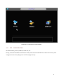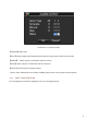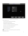
1
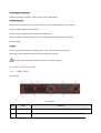
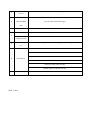
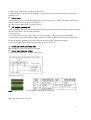
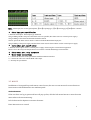
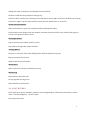
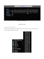
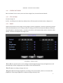
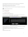
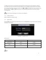
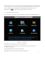
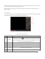
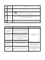
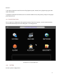
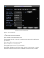
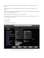
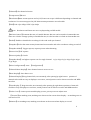
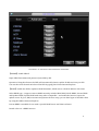
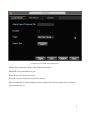
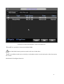
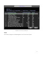
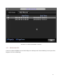
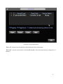
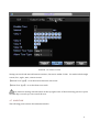
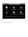
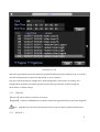
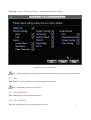
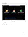
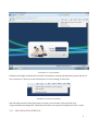
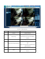
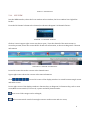
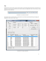
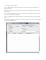
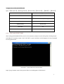
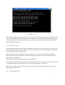
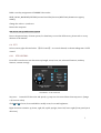
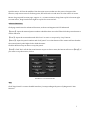
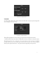
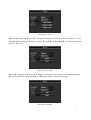
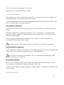
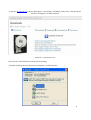
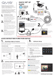
EmbeddedDVRUserManual
1. PRECAUTIONS
Pleaseobservethefollowingprecautions,inordertoavoiddamageorlossofdatacausedbyimproper
operation.
DVRshouldworkonpropertemperatureandhumidity.
DonotinstallDVRinhumid,dustyorsmokyenvironment.
Requireasolidmountingsurfaceforinstallation.
Donotblockanyventilationopenings.Installunderthemanufacturer'sinstructions.
Donotspillliquidofanykindondevice.
Donotputanyotherequipmentondevice.
Donotdismantlethedevice.
SelectspecifiedHDDbymanufacture.
1/90
2. NOTE
Thisusermanualisforreferenceonly,subjecttoavailableproducts.
Thisusermanualmaycontaininaccuratedataorprintingerror.
Updatestothemanualorproductsthemselveswilloccurwithoutfurthernotification.
Allpicturesnotfromthesamemachine,showingillustrativepurposesonly.
Contactthecustomerservicedepartmentwhenyouhaveanyquestionorwantnewestsoftwareand
file.
2/90
Content
1.
PRECAUTIONS ...................................................................................................................................... 1
2.
NOTE ................................................................................................................................................... 2
3.
PRODUCT INTRODUCTION.................................................................................................................... 5
3.1.
SUMMARY ............................................................................................................................. 5
3.2.
FEATURES .............................................................................................................................. 5
3.3.
INSTALLATION ....................................................................................................................... 6
3.4.
PANEL INTRODUCTION .......................................................................................................... 7
3.5.
MOUSE .................................................................................................................................11
3.6.
INPUT METHOD ....................................................................................................................12
3.7.
POWER ON/OFF....................................................................................................................13
3.8.
ICON.....................................................................................................................................15
3.9.
LIVE VIEW .............................................................................................................................16
4.1 RIGHT BUTTON MANU ......................................................................................................................17
5
6
4.2
MAIN MENU INTRODUCTION................................................................................................21
4.3
SEARCH.................................................................................................................................22
4.4
CONFIGURATION ..................................................................................................................24
4.5
STORAGE ..............................................................................................................................42
4.6
OUTPUT................................................................................................................................47
4.7
MAINTAIN.............................................................................................................................54
4.8
SHUTDOWN..........................................................................................................................58
WEB&CLIENT ......................................................................................................................................59
5.1
WEB OPERATION ..................................................................................................................59
5.2
CLIENT OPERATION...............................................................................................................68
FUNCTION...........................................................................................................................................69
6.1
DDNS Function......................................................................................................................69
6.2
Port mapping........................................................................................................................72
6.3
NTP function.........................................................................................................................74
3/90
7
6.4
PTZ .......................................................................................................................................75
6.5
Voice Intercom .....................................................................................................................79
6.6
HDD redundancy...................................................................................................................80
6.7
HDD S.M.A.R.T......................................................................................................................80
APPENDIX ...........................................................................................................................................83
7.1
TERMS ..................................................................................................................................83
7.2
HDD CAPACITY CALCULATION ...............................................................................................84
7.3
Common Faults.....................................................................................................................87
4/90
3. PRODUCTINTRODUCTION
3.1. SUMMARY
OurEmbeddedDigitalVideoRecorderisanexcellentdigitalsurveillanceproductwhichadoptsH.264
videocompression,harddiskrecording,TCP/IPtransmission,andaLinuxbasedOSinadditionto
someofthemoreadvancedtechnologiesintheinformationtechnologyindustry.Thisenablesamore
stable,reliableandhighpicturequality.
Theseproductssupportsynchronizedvideoandaudiorecording,playback,andmonitoring.This
seriesalsosupportsnetworkbasedsystemcontrol,aswellasexcellentnetworkstreaming
capabilities.
3.2. FEATURES
LIVEVIEW
CVBSinterface,TV,VGA/HDMIsynchronousoutput.
COMPRESSION
H.264videocompression,G.711audiocompression,supportsD125fpsresolution.
RECORDING
Recordingmodesincludemanual,time,alarm,motiondetection,etc.;SupportSATAHDDandlocal
diskS.M.A.R.T.technology,SupportUSBbackupandinternetbackup.
PLAYBACK
Playbacksearchbyvariousconditions,localandnetworkplayback;supportmultiplechannel
simultaneousplayback,supportfast,slow,rewindandframemode;supportexacttimeplayback.
CMERACONTROLANDALRM
Remotecameracontrol,Multi-channelalarminputinterfaceforconnectingvarioustypesalarm
equipment;Motiondetectionalarm,videolossalarm,maskingalarm;Multi-channelalarmoutput,
alarmlinkageandon-sitelightingcontrol.
COMMUNICATIONINTERFACE
USB2.0highspeedinterfaceconnectingvariousbackupdevices;StandardEthernetinterface,work
undervariousnetworks.
5/90
NETWORKPROTOCAL
SupportTCP/IP,UDP,RTP/RTSP,DHCP,PPPoE,DDNS,NTPetc.;supportnetworkreal-timelive
view,recording,playback,control;built-inWEBServer,IEbrowserfordirectaccess.
OPERATIONMODE
Supportthefrontpanel,remotecontrols,mouseandsoonmanykindsofoperatingmode;Withsimple,
intuitivegraphical;Withsimple,intuitivegraphicalinterface.
3.3. INSTALLATION
3.3.1.
CHECKDVRANDACCESSORIES
Pleasecarefullycheckthecontentsaspackinglist.Ifanyoftheitemsaremissing,pleasecontactwith
yourdealer.
3.3.2.
HDDINSTALLATION
Preparation
PrepareaCrossScrewdriver.
Note:HDDquantitybyeachmodel’sspecificationsshallbefinal,HDDcapacityupto64TB.
Steps
Removethemetaltopcoverbyremovingtwoscrewsfromthesidesofthecover.
Placetheharddisksonaflattableandfastenitbyscrews.
ConnectthepoweranddatacablestotheHDD.
Reinstallthemetaltopcoverandfastenitbyscrews.
Caution
OnlyuseHDDspecifiedbythemanufacturer.
HDDwillbeformattedautomaticallyduringstartup,itmaycausedataloss.
RecordingdurationisdecidedbyHDDcapabilityandDVRparameters(recordingsetup,encoding
setup).Pleaseseetheforminchapter7.2.
3.3.3.
WIRINGINSTALLATION
6/90
Preparingforinstallation
Camera,displayer,AVcable,cable,mouse,otherkindscables.
InstallationSteps
DVRinahorizontalposition,connectcameratovideoinputinterfaceinbackpanel.
Connectvideooutputtothedisplayer.
ConnectcabletoRJ45interfacewhenaccessnetwork.
MouseshouldbeUSBinterfacetype,frontorbackpanelUSBinterfacebothwork.
Powersupply.
Caution
ForanexternalalarmdeviceorPTZ,pleaserefertotherelevantinstructions.
DVRpowerlinesshouldbeunderalllinesconnectedcorrectly.
Notethepowerparameterswhenaccesstoavarietyofpower.
3.4. PANELINTRODUCTION
3.4.1.
FRONTPANEL
FrontPanel:
Frontpanel:
Index
Name
Function
1
Power switch
Receiveremotecontrolsignal;
2
USB interface
Connect USB devices such as U drive
7/90
3
receiver
Power/RUN/REC/
4
Receive remote control signals
Remote control
NET/ALARM
Light for
power on state / the machine to work/video status/
network connection/alarm trigger
LED
5
DVD burner
DVD burning
Direction key
Cursor keys , select menu option
ENTER
Menu setup confirmation
6
confirmation key
7
Channel selection
Achieving channel selection single , picture to enlarge
key
Menu key ESC return key
FN accessibility key PTZ dome control key
REC video key PLAY playback key
8
Function key
PRE next PAUSE pause key
NEXT preceding STOP stop key
MODE image key MUTE mute key
9
Shuttle key
Playback fast forward Rewind control screen switch
Back Panel:
8/90
BackPanel:
No.
Physical
ID Description
interface 1
Video input
16-channel video input (BNC)
2
Audio input
16-channel audio input (RCA)
3
Video output
1 channel video output interface(BNC)
4
Audio output
1-channel audio output interface (RCA)
5
Intercom input
1-channel intercom input
6
Extension interface
Loop-out extention interface
7
RS 232 interface
1-channel RS232 communication interface
8
VGA interface
1-channel VGA display interface
9
HDMI interface
HDMI HD output interface
10 LAN interface
1-channel network interface (RJ45)
11
USB interface
1-channel USB Interface (available to U disk backup or mouse)
12
13
14
I/O Alarm, serial
interface
Fan outlet
interface
Power interface
Alarm input/output interface , PTZ interface
ATX power supply fan air outlet
AC power connector
Alarm input and output connections
l Alarm input
A. Alarm input is grounding alarm input.
9/90
B. Alarm input demand is the grounding voltage signal.
C. When the alarm is connected with two DVRs or connected with DVR and other equipments, it should be
isolated by relay.
l Alarm output
Alarm output can not be connected with high-power load (no more than 1A). When forming the output loop it
must prevent the big current from relay damage. Use
the contact isolator when there is a high-power load
l PTZ decoder connections
A. The grounding of the PTZ decoder and DVR must be shared otherwise the common-mode voltage will lead to
the PTZ control failure. The shielded twisted pair
is recommended.
B. Avoid the entrance of high voltage. Make the layout reasonably. Take precaution from the thunder.
C. In the outlying end connect 120Ω resistance paralleled to reduce the inflection and insure the signal quality.
D. The 485 AB lines of DVR can not connected with other 485 output equipments paralleled.
E. The voltage between the AB lines of the decoder must be less than 5V
l Front equipment grounding note
Bad grounding can lead to the burnout of the chip.
l Alarm input type unlimited
The DVR alarm output port is constant opening type
4-CH Alarm Terminal
Note: Alarm input, the need to ground phase, 【NO】is opening type.
8-CH and 16-CH Alarm Terminal
10/90
Note: Alarm input, the need to ground phase, 【NO】is opening type, 【NC】is closing type 【NO】
,
is the common
u Alarm input port specification
1 channels alarm input. Alarm input type unlimited.
The grounding and the com port of the alarm sensor are parallel (The alarm sensor is external power supply).
The grounding of the alarm and the DVR should be shared.
The NC port of the alarm sensor must be connected with the DVR alarm input port.
The grounding of the power supply and the alarm sensor must be shared when used in external power supply.
u Alarm output port specification
1 channels alarm output. There is external power supply when using the external alarm equipment.
Please refer to the relay relevant parameters to avoid the overload that damages main machine.
u Alarm output port relay parameters
u Speed dome connections
1、Connect the 485 lines of the speed dome with the DVR 485 interface.
2、Connect the video line with the DVR video input.
3、Electrify the speed dome.
3.5. MOUSE
Inadditiontofrontpanelkeysandremotecontrolmenu,theusercanusemouseformenufunctions.
InsertmousewithUSBinterfaceintomachinepanel.
ClickLeftButton
Iftheuserdoesnotlogin,passwordboxwillpopupfirst;clicktheleftmousebuttontoenterthemain
menuwhenreal-timemonitoring.
LeftclickmousetheOptionsiconenterthemenu.
ExactInstructionsoncontrol
11/90
Changethestateofcheckboxanddynamicdetectionblock.
Clickthecomboboxdrop-downlistwillpopup.
Under3DPTZcontrolmode,clickthemouseanddragtolowerrightcanachieve3DPTZcontrol.drag
fromlowerrighttoupleft,make3DPTZcontrolnarrow,detailsreferto4.1.2PTZ.
DoubleClickLeftButton
Selectandconfirmoropen,forexample,double-clickplaybackvideo.
Undermulti-screendoubleclickonechannelcanmakethepicturefullscreen;double-clickagainto
returntothepreviousmulti-screen.
ClickRightButton
Pop-upcontextmenuundermonitorscreen
Exitwithoutsavingundermenuinterface.
TurningWheel
IncreaseordecreasevaluewhenfilldigitalboxSwitchcomboboxoptions.
Flipupanddownforlistbox.
AchievePTZ3Dzoomfunction.
MouseMove
Selectcontrolsincurrentcoordinatestomove.
MouseDrag
Selectmotiondetectionarea.
Setupregionalcoveragearea.
Select3DPTZzoomfunction.
3.6. INPUTMETHOD
Intheinputbox,choosenumbers,symbols,caseinEnglishinput.Clickleftmousebuttontoselect
value;←meansbackspace,_meansaspace.
LetterInputInterface
12/90
DIAGRAM3-1LETTERINPUTINTERFACE
NumberInputInterface
DIAGRAM3-2NUMBERINPUTINTERFACE
SpecialSymbolsInputInterface
DIAGRAM3-3SPECIALSYMBOLSINPUTINTERFACE
ChineseInputInterface
DIAGRAM3-4CHINESEINPUTINTERFACES.
3.7. POWERON/OFF
3.7.1.
POWERON
DVRinstalledcorrectly,switchonwithpowerlightison,DVRwillbootupautomatically.Different
modelhavedifferentbootupstatus,pleaserefertotheFront-panelIntroduction.
DVRwilldetectthehardwarewhenpoweron,theprocesswilllast20secondsmoreorless.Afterthe
detection,DVRmakea“Buzzing”soundandenterintoamulti-screenliveview,usercanoperatenow.
PleaserefertoXXX.MainMenuIntroductionandOtherIntroduction.
13/90
Ifrecordingtimecontainpoweruptime,DVRwillautomaticallystarttimingrecordingwhenpower
on.
DIAGRAM3-5LIVEVIEW
Note:PowersupplyhastomatchwithDVR,anyothersubstitutesarenotallowed.
3.7.2.
POWEROFF
Holddownon-offkeytoturnoffdevice.
【MainMenu】→【Poweroff】→【Poweroff】.
14/90
DIAGRAM3-6TURNOFFDEVICE
Note:turnoffdeviceandswitchoffpowerwhenchangingHDD.
3.7.3.
OUTAGERECOVERY
Rebootafteranoutageorforcefulshutdown,DVRwillsavetherecordbeforeoutageandreturnto
normaloperationmode.
3.8. ICON
3.8.1.
STATUSICONS
:Record
:Videoloss
:Motiondetection
:Channellock
:Allowsscreentoswitchpolling.
3.8.2.
OPERATIONICON
15/90
:NotSelected
:Selected
:DownMenu
:Confirmrevise/getintomenu.
:Cancelrevise/cancelgetintomenu
:Setparameters
:Saveparameters
:Restorefactorysettings,returntothelastsetofparametersafterthemodified
parameters,
:Applycurrentsettothesystem.
:Copycurrentsettootherchannels.
:Entertheconfigurationmenu.
:Configalarm,videodetectiontrigger’sprocessing
3.9. LIVEVIEW
PoweronDVRandentryintoliveviewmode:therearedate,time,channelnamesiconswhichindicate
recordingandalarmstatusdisplayonscreen. Switchdisplayscreensbythefrontpanel,remotecontrolormousecontrol.
Whenenablethescreenmessageforexternalalarm,videoloss,masking,motiondetection,network
andIPconflictalarm,thebelowinterfacewouldpopupwhenthosealarmoccur.ShowsasDiagram3-7
AlarmStatuse:
16/90
Diagram3-7AlarmStatuse
4OPERATIONGUIDE 4.1RIGHTBUTTONMANU
Clicktherightmousebuttonafterbootingintothereal-timebrowserinterface,actionmenupop-up,
showsasDiagram3-8Rightbuttonmenu.
17/90
DIAGRAM3-8RIGHTBUTTONMENU
4.1.1 SCREENSWITCHING
Max16channelinonescreen,usercanchoosesingle,four,nineandsixteenchannel.
4.1.2 PTZCONTROL GetintoOutputà
P/T/Z, SetPTZprotocol,baudrate,addressbits,PTZcanwork,fordetailsrefertochapter6.4.
4.1.3 IMAGE
Adjustthespecifiedscreen(singlescreen)imagecolorhue,brightness,contrast,saturation,gainand
white-levelparameterssettwotimeperiodsaccordingtothelocalenvironmentdifferencebetween
dayandnightforeachadjustment periodset,thedevicewillautomaticallyswitchtothebestvideo
quality.AsshowninDiagram3-9ImageColor.
DIAGRAM3-9IMAGECOLOR
【Period】Twoperiodscanbesetaccordingtoambientlightduringthedayandnight,devicewill
automaticallyswitchconfigurationtime.NeedtoselecttheEnablebox.
【Hue】Adjustaccordingtoimagecolorcast 【Brightness】Visualimagebrightness,accordingtotheenvironment,reducesorincreasesthe
brightnessoftheimagebrightnesstomaketheimagerelativelyclear.
18/90
【Contrast】Adjustimageofblackandwhiteinproportion,thegreaterratio,thebrighterimage.
【Saturation】Imagecolorpurity,thegreatervalue,themorecolorfulimages.
【Gain】Enlargetheimagesignaltoimprovesignalquality.
【WhiteLevel】Changethewhitelevelreferencevalue,toimprovethebrightnessoftheimagedisplay.
Note:Differentmodedifferentfunction
4.1.4 RECORDINGSEARCH
Referto4.3recordingsearch.
4.1.5 MANAUALRECORDING
Remark:manualusermusthave"RECORD"right
Inliveviewscreen,clickon 【ManualRecord】,orpressthe 【video】 keyonremotecontrolinto
manualrecordinginterface,asshowninDiagram3-10RecodingControl.
DIAGRAM3-10RECODINGCONTROL
【Manual】Thehighestpriority,nomatterwhatthecurrentstatusofeachchannel,thecorresponding
channelswillmakecommonrecordingwhenpress"Manual"button;
【Schedule】Recordaccordingtorecordingtypeinrecodingset.(CommonmotionDetectionand
alarm);
【Stop】Stopallchannelrecording.
19/90
Tochangerecordstatusofonechannel,firstlychecktherecordingstatusofthechannelisselected
non-selected(non-selectedindicatesthatthechannelisnotrecording;selectedindicatesthechannel
inrecordingmode).Thenusemousetoclick,oruse【t】or【u】arrowkeysmovetheactiveboxtothe
channel,thenuse 【p】or【q】arrowkeysorcorrespondingnumberkeytoswitchthechannel
recordingstatus.
Note:Allselectedcanchangerecordstatusforallchannels
4.1.6 ALARMOUTPUT
Refertochapter4.6.2alarmoutput
4.1.7 MAINMENU
Clickthe【MainMenu】,inputusernameandpassword,click【OK】toenterthesystemmenu.Asshown
inDiagram3-11system
DIAGRAM3-11SYSTEMLOGIN
Defaultusers:
UserType
Name
DefaultPassword
Administrator
admin
123456
User
user
123456
Hidden
default
default
FORM3-1DEFAULTUSERS
Note:
20/90
Passwordsecurity:occuralarmafterthreetime’swronginputandsystemlockoutin30minutesafter
5unsuccessfullogin.Forsecurityconsideration,pleasemodifythedefaultpassword.Forinformation
onhowtoaddgroups,usersandmodifyusersinformation,pleasereferchapter4.4.5Uses
Management,Click
totogglethecharacterinputmethodinmousemode.
4.2 MAINMENUINTRODUCTION
Themainmenuasshown,therearesearch,configuration,storage,output,maintainandshutdown.
DIAGRAM3-12SYSTEMMANU
【Search】Searchrecodingbytype,channel,timeandplayback.
【Configuration】recording,motiondetection,abnormal,alarm,system,networkanduser
managementconfigurations.
【Storage】HDDmanagementandbackupmanagement.
【Output】PTZ,alarmoutput,serialandoutputmodeconfiguration.
21/90
【Maintain】todisplaythesystemloginformation,versioninformation,streamstatistics,andonline
userandsetthefactorydefault,automaticmaintenance.
【Shutdown】Logofftheusermenu,turnoffthemachine,restartthesystem,andswitchuserand
otheroperations.
4.3 SEARCH
Inreal-timemonitoringscreen,clicktherightmousebutton,click 【search】,orentervideoplayback
viamainmenuinterface,asshowninDiagram3-13RecordSearch.
DIAGRAM3-13RECORDSEARCH
Index
Type
Description
1
Calendar
2
Time
Selectrecordsearchstartandendtime.
3
Play
Playbackcontrol:stop/play,pause,fast,slow,previous/nextframeinpause.
4
Recoding
mode
Choosesearchedrecordingmode,includingwhole,outsidealarm,motive
detection,wholealarmrecording.
5
Channel
Choosesearchedchannel
Clickthecalendaricon
toshowtherecordlist(onlythedateswith
greenbackgroundtakerecords.)andthenclickaspecificdatetocallthe
record.Thelistwillbeupgradedautomatically.
22/90
6
Play
Choosetoplaythepreviousornextfile;choosetoplaythepreviousornext
channel.
7
Search
Choosethestarttime,channel,andclick“search”willdisplayresultsinthe
list.
8
Backup
Tick“
”tochoosebackupfileinfilelistbox,clickbackupbutton,cancel
backupfile---click“√”frombackupmenu“√”.
9
RecordList
128videorecordsshowsinsearchinglistchoosefileandpressenteror
doubleclickmousetoviewrecord.
Filetype:R—normalrecord,A—alarmrecord;M—motiondetectionrecord.
10
Channel
Choosethechanneltoplayback.
FORM3-2RECORDSEARCHINTERFACEDESCRIPTION
PlaybackControl:
Key
Description
Videoplayback:
Underplaybackmode,pressingthiskey,
youcangetavarietyoffastcycleswitching
speeds;fast-forwardbuttoncanbeusedas
slow-releasebuttonreverseswitchkey.
Fast-forward
button8
Videoplayback:
Slowkey|
Play/pause►/;
Underplaybackmode,pressingthiskey,
switchcyclicallysupportavarietyof
slow-releaserate,slowreleasebuttoncan
beusedasfast-forwardbuttonreverse
switchkey.
Remark
Actualplayratebasedon
version
Play/pauseswitchwhenslow-play
Backward:
Singleleftclickbackwardkey
Backwardkey|
Manualsingleframe
singleframeplaybackbyclicking
playback
t│and│uwhencommonplaybackpause
Toplaybackwardsandsingle
clickagaintostopbackrun
undercommonplayback
Rewindorsingle-frame
playback,presstheplaybutton
►/;toenterthenormal
playback.
FORM3-3PLAYBACKCONTROL
23/90
Remark :
1,theplayerplaybackcontrolbarshowfileplaybackspeed,channel,time,playbackprogressand
otherinformation.
2,playbackspeedandrewindfunctionarerelatedtoDVRversion,andpleasepromptontheplayer
panelshallprevail.
4.4 CONFIGURATION Usercangetintoconfigurationthroughmainmenu;Functionofsystem,record,network,alarm,
accountandabnormityasshowninDiagram3-14Configuration.
DIAGRAM3-14CONFIGURATION
4.4.1 SYSTEM Getintosystemconfiguration:
24/90
DIAGRAM3-15SYSTEMCONFIGURATION
【Time】:Setthecurrenttime
Note:Clicktosavethetimemodification.
【DateFormat】:Tomodifythedatedisplayformat
【DaylightSavingTime(DST) 】:Click“DST”toenablethefunction,andenterthelocalDSTstarting
andendingtime.
【DateSeparator】:Toselecttheseparatorfordate
【TimeFormat】:24hror12hrdisplaymode
【Language】:languageselectionsvarybydifferentmodel).
【FullHDD】:WhenHDDisfull,therearetwooptions:“Overwrite”or“Stoprecording”.Ifyouselect
“Overwrite”,theDVRwilloverwritetheearliestrecordedfilesandcontinuerecordingasallHDDin
25/90
DVRarefull.Ifyouselectthe“Stoprecording”optiontheDVRwillstoprecordingwhenitreaches
capacity. 【PackDuration】:Tosettimelengthforeachrecord,defaultis60minutes,themaximumis120
minutes.
【DVRNo.】:NumbermorethanoneDVR,click“Ad”buttononremotecontrolandinputanumberto
selectthecorrespondingDVRtooperate.
【VideoStandard】standard:PAL/NTSC(matchcameramodel).
【AutoLogout】:Thisrangesfrom0-60minutes.0meansnosetting.DVRwillautomaticallyletuser
quitafterstandbytime’svacancy.
4.4.2 RECORD Basemanagement
The“Basemanagement”interface:
DIAGRAM3-16RECODINGCONFIGURATION-BASICALLYCONFIGURATION
26/90
【Channel】thechannelselection
【Compression】H.264
【Resolution】mainstreamoptionsareD1/CIF,frameratescopeisdifferentdependingonchanneland
resolution.VicestreamsupportD1/CIF.Mainstreamparametersareselectable.
【FPS】PAL:1fps-25fps;NTSC:1fps-30fps.
Note:ResolutionandframeratearevarydependingonDVRmodel.
【BitRateControl】ConstantBitrateorVariableBitrates.BitratecanbesettedinConstantBitrate. Thereare6levelsofimagequalityinVariableBitrate,6isthebestbutitisfixedinConstantBitrate.
【Audio】Enableordisabletherecordingofvideoandaudioperchannel.
【Snapshot】Selectthemainstream/extensionalstreamaudioandvideoresolutioncodingonandoff.
【SnapshotMode】Triggercapture,capturepicturewhenalarming.
【PictureSize】CIFcapture
【PictureQuality】6levels
【SnapshotRate】sethighestcapturerateforsinglechannel,1s/pc2s/pc3s/pc4s/pc5s/pc6s/pc
7s/pc8s/pc
【MoreConfiguration】enter 【Configuration】
【ChannelNameDisplay】showchannelnameinscreenornot
【DateDisplay】showdateornot
【ChannelDisplay】dragchanneltitle,saveinstantly,afterquittingbyrightbutton,positionof
channeltitlewouldnotvaryindisplayerormonitor,variedpositioncanbeshownrecorderandWEB
interface.
【TimeDisplay 】dragtimetitle,saveinstantly,afterquittingbyrightbutton,positionoftimetitle
wouldnotvaryindisplayerormonitor,variedpositioncanbeshownrecorderandWEBinterface.
【VideoCover】4zonespreviewanddisplayprotect,privacyzonecanadjustarea. 【Preview】setmaskingzone,maskingzoneshowninthescreenwhendisplay,nomaskingzonein
webandrecord.
【Monitor】setmaskingzone,maskingzoneshowninthescreenwhendisplayorrecord.
27/90
DIAGRAM3-17MORECONFIGURATIONS
【Copy】copyonechannel’sconfigurationtootherrecordplan RecordConfiginterface:Diagram3-18RecordingConfiguration-recordingplan
28/90
DIAGRAM3-18RECORDINGCONFIGURATION-RECORDINGPLAN
【Channel】:Toselectchannel.Green,yellowandredrefertothenormal,MDandalarmrecording
type.Modifyitin【Edit】.
【Copy】copyonechannel’sconfigurationtoother
【Edit】editplaninterfaceDiagram3-19EditPlan:
29/90
DIAGRAM3-19EDITPLAN
【Time 】recordingtime,6recordingtimezonecanbeseteveryday
【Normal】fornormalrecord
【MovingDetection】ForMovingdetection
【Alarm】Foralarmrecord
4.4.3 NETWORK SettheDVRnetworkparametersin“Network”interface.ThedefaultIPaddressis192.168.1.88
Basesetting
Basesettinginterface4-13: 30/90
DIAGRAM3-20NETWORKCONFIGURATION-BASECONFIGURATIONS
【DHCP】EnabletheDVRtoobtainanIPaddressautomatically.Ifthisisenabled,theDVRwillreboot
andsearchforaDHCPserver,andthenassignadynamicIPaddress.ThedynamicIPaddresswillbe
displayedinthemenu.EnterastaticIPaddressifthereisnoDHCPserviceavailable.Ifyouareusing
theadvancedfeaturePPPoE,thentheIP/mask/gatewayandDHCPareunabletobechanged.
【IPAddress】use(pq)orinputnumberstomodifyIP,thenset 【subnetmask】 and 【default
gateway】forthisIP.
【FirstDNSServer】DNSserverIP
【AlternateDNSServer】DNSalternateIP
【PhysicalAddress】physicaladdressofcurrentnetport
Advanced
Advanceinterface(Diagram3-21NetworkConfiguration-Advanced):
31/90
DIAGRAM3-21NETWORKCONFIGURATION-ADVANCED
【PPPOE】enablePPPOE
InputPPPOEusernameandpasswordprovidedbyISP.
Operation:Usingthisfeature,theDVRwillautomaticallyobtainapublicIPaddressfromyourISP. YoucanthenvisitthewebinterfaceoftheDVRbytypingthisIPintoInternetExplorer. 【DDNS】enabletheDVRtoupdateaDDNShostname,whichrunonafixedIPaddresswebclient.
SelectDDNStype(supportsvariousDDNScurrently,includeCN99DDNS,NO-IPDDNS,PrivateDDNS
andDyndnsDDNS,SysdnsDDNSwithmanyothercompatible)andenablethefunction;inputthe
updateserverIP,port,DNS,usernameandpassword.Oncesetup,youcanthenloginviatheWebclient
byusingthisDNSinInternetExplorer.
PrivateDDNSisavailableforusewithaspecificDDNSserverandclientsoftware.
Detailsreferto6.1DDNSfunction
32/90
【NTP】on/offNTP.NetworkTimeProtocol–allowstheDVRtosyncwithSNTPtimeserver
automatically.
HostIP:inputIPofNTPserver
Port:ThisSNTPsupportTCPonly,theuniqueportis123.
Updatecycle:timeintervalbetween1minand65535min.
Timezone:London:GMT+0,Berlin:GMT+1, Cairo:GMT+2, Moscow:GMT+3,NewDelhi:GMT+5, Bangkok:GMT+7, HongKong/Peking:GMT+8, Tokyo:GMT+9, Sydney:GMT+10, Hawaii
standardtime(HST):GMT-10, Alaskastandardtime(AKST):GMT-9, Pacificstandardtime(PST):
GMT-8, Mountainstandardtime(MST):GMT-7, Centralstandardtime(CST):GMT-6,Eastern
standardtime(EST):GMT-5, Atlanticstandardtime(AST):GMT-4, Brazil:GMT-3, middleAtlantic:
GMT-2.
【IPFilter】
DVRauthoritymanagement,ifyouenablethewhitelist,onlytheDVRinIPlistisallowedto
connect.Thissystemsupportsamaxof64IPs.
【On-lineUser】range:0-10,0indicatesthatnoconnectionsareallowed.
【Networkmonitoringconnections】0-32shouldbeproper.NeedCheckfirstthenbrowserealtime
videoonthenetwork,thenumberofconnectionsdependingonnetworkbandwidth,thegreaterthe
number,thegreaterthenetworkload,theimpactofvideoplaybacksmooth
Theautomaticsettingadjuststhesesettingsbasedonavailablenetworkresources.
【Speedyonlinedownload】0-8shouldbeproper.
【NetworkTransmissionQOS】FluencypriorityorPictureQualitypriorityorself-adaption
Y,accordingtothesetting,thenetworkautomaticallyadjuststhestream.
【Speedyonlinedownload】ifenabled,speedis1.5-2timestonormalspeed.
【HTTP】default:80
【TCP】default:8000,variable
【UDP】default:8001,variable
【UPnP】Protocolontherouterautomaticallyopenportmapping,makesureUPnPfeatureisenabled
ontherouter,detailsrefertochapter6.3.3
【Multicast】tick‘Multicast’andsetagroupin‘Set’,IPshouldbelimitedasfollowpicture,portnolimit.
33/90
【Email】SetthesendermailboxSMTPserverIPaddress,port,username,passwordandsender’s
mailbox,mailSSLEncryption.
EmailtitlesupportChinese,EnglishandArabicnumeralsinput,Maxinput32characters.Maxsupport
3ReceiveAddressesandSSLEncryptionMailbox.
【FTP】:Tick“FTP”andclick“Set”
SetFTPserverIPaddress,portanddestinationfolder.SystemwillcreatefoldersbyIP,timeand
channelifthereisnoremotefolderspecified.
FTPusernameandpassword
Setamaximumfilesize,channel,time,typeandetc.
SetFTPfilelength.Uploadthewholerecordifthefilelengthissmallerthansetting;leaveoutthe
exceedpartifthefilelengthisexceedthesetting;0referstouploadingtheentirerecordinany
condition. Setuptotwotimeperiodsandchoosefrom3differentrecordtypesforchannels.
【AlarmCenter】reservedinterface
Networkstatus
DisplaythecurrentDHCPPPPoEandIP.
4.4.4 ALARMCONFIGURATION
Localalarm
LocalAlarminterface(Diagram3-22AlarmConfigurations):
34/90
DIAGRAM3-22ALARMCONFIGURATIONS
【AlarmInputChannelNo.】selectthealarminputchannel
【Enable】thespecifiedalarmin/out
【Type】selectthealarmcircuittype.
【Copy】copytheconfigurationtoanotherchannel
【ProcessMode】enteralarmlinkageinterfaceDiagram3-23AlarmConfiguration-localalarm
–ProcessMode-Period:
35/90
DIAGRAM3-23ALARMCONFIGURATION-LOCALALARM–PROCESSMODE-PERIOD
【Period】 setalarmactiveperiod
36/90
DIAGRAM3-24ALARMCONFIGURATION-LOCALALARM–PROCESSMODE-LINKAGE
【Linkage】 on/off【RecordChannel】,【PTZ】,【Tour】,【Snapshot】 linkageandselectchannel.
37/90
DIAGRAM3-25ALARMCONFIGURATION-LOCALALARM–PROCESSMODE-ABNORMITY
【Abnormity】:enableordisable【AlarmOut】,【ShowMessage】,【SendEmail】 and【Buzzing】
Timedelayforalarmcancelis10-300s
Notice:somemodelshavenoLOCALALARMFunction;pleaserefertotheProductSpecification.
Videodetection
【motiondetection】motiondetectionandalarm
【zonesetting】22*18=396zonesmask
【Sensibility】6grades
【management】assameaslocalalarm
【preview】alarmpreview
【videolose】detectvideolosesandalarm
38/90
【management】assameaslocalalarm
【preview】alarmpreview
4.4.5 USERMANAGEMENT
Note:
Groupandusernamescanbefrom1-6charactersinlength.Validcharactersincludeletter,numbers,
andlimitedsymbols:underline,subtractionsign,dot,youmaynotuseaspaceasaleadingorending
character.
Thereisnolimittothenumberofgroupsorusers.Bydefaulttherearetwodifferentgrouplevels:
adminanduser.
Usermanagementdeterminedupontwolevels:thegroupandtheuserlevel.
Groupandusernamescannotbeduplicated,andeachusercanonlybelongtoonegroup.
UsermanagementinterfaceasDiagram3-26UserManagement:
39/90
DIAGRAM3-26USERMANAGEMENT
【Addusers】addgroupmemberinformationandsetauthorities.
Defaultusersare:“admin”,“user”andhidden“default”,thepasswordoffirsttwousernameis123456.
“admin”hasadvancedauthorities;“user”onlyhassurveillanceandplaybackauthority.
Hiddendefault:operateinpassword-lessloginmode,cannotdelete,DVRlogininthisname
automaticallyif“nouserlogin”,usercanreviselimitsofpowerthenoperatesomewithoutlogin.
Enter【Addusers】inputusername,passwordandselectgroupandreusableoptions.Reusableallows
theaccounttobeusedbymultiplelogins.
Userscanonlybelongtoonegroup. Userrightscannotexceedgrouprights.
【Modifyusers】modifyexistinggroupmemberinformationandauthority.
【Addgroup】addgroupandsetgroupauthorities
Setagroupandauthorize60itemsincludingcontrolpanel,shutdown,liveview、playback,record,
recordbackup,PTZcontrol,account,systeminformation,alarmin/outsetting,systemconfig,search
log,logdelete,upgrade,operationauthority,etc.
【Modifygroup】modifyexistinggroupinformation.
【ModifyPassword】changepassword
Selectausernameinputtheoldpasswordandnewpasswordtwice.
Click【Save】toconfirm
Passwordcanbein1-6numbers,lettersorsymbol;blankinbeginningandendisinvalid.
Theaccountwithmanagementauthoritycouldchangeothers’password.
4.4.6 ABNOMITY
AbnormityinterfaceasDiagram3-27:
40/90
DIAGRAM3-27ABNORMITY
【NoDisk】alarmwhenHDDisnotpresentorcannotbedetected.
【Process】includes:【AlarmOutput】, 【DisplayOnScreen】 and 【SendEmail】.
【DiskNoSpace】alarmwhenharddiskcapacityislowerthansetting. 【ProcessMode】issameas 【NoDisk】’s 【ProcessMode】
【NetworkFailure】alarmwhennetworkisnotconnected.
【ProcessMode】includes【AlarmOutput】, 【DisplayOnScreen】 and 【SendEmail】andrecording
linkage.
【IPConflict】alarmwhenIPaddressconflict.
【ProcessMode】 issameas 【NoDisk】’s 【ProcessMode】
【DiskError】 alarmwhenthereiserrorinreadingandwritingharddisk.
【ProcessMode】 issameas 【NoDisk】’s 41/90
【ProcessMode】issameas 【NoDisk】’s 【ProcessMode】
4.5 STORAGE
4.5.1 HDDMANAGEMENT
MaintainandmanagelocalHDD:Diagram3-28StorageManagement
DIAGRAM3-28STORAGEMANAGEMENT
BaseConfiguration “BaseConfig”asDiagram3-29HDDmanagement–baseconfiguration,showsDVRstoragecapacity,
availablespaceandworkingstatus.
42/90
DIAGRAM3-29HDDMANAGEMENT–BASECONFIGURATION
【Format】itispossibletoformatanindividualHDD.
Note:Harddiskformatoperationresultinthelossofvideodata
【Set】tosetHDDasread-write,readonlyorredundancymode.Inreadonlymode,videodatacannot
becovered.
HDDS.M.A.R.Tintelligentdetection
43/90
DIAGRAM3-30S.M.A.R.TTECHNOLOGY
Record
Recordmenu,asDiagram3-31HDDManagement-record,showsstart-stoptime.
44/90
DIAGRAM3-31HDDMANAGEMENT-RECORD
4.5.2 RECORDBACKUP
ConnectanExternalUSBdevicewiththeUSBporttobackupinthe“RecordBackup”menu(interface
Diagram3-32RecordBackup).
45/90
DIAGRAM3-32RECORDBACKUP
【Detect】:IdentifyexternalUSBdeviceanddisplaythedeviceinformation.
【Backup】:ticktheexternaldeviceandclick【Backup】toenterthebackupmenu(asDiagram3-33
Backup).
46/90
DIAGRAM3-33BACKUP
Selecttherecordstart-stoptimeandclick【Add】toaddinlist;duplicateitbyinputtingthestart-stop
timeagain;click【Delete】toclearthefileslist. Ticktherecordyouwantandclick【Start】tobackupanddisplaytimeremaining.
【Delete】deletealldatainUSBbackupdevice
Note:USBbackupcarryplayerautomatically
Note:thisoperationprobablycausepermanentdataloss
4.6 OUTPUT
ThefollowingDiagram3-34PeripheralManagementshowstheperipheralmanagementinterface
47/90
DIAGRAM3-34PERIPHERALMANAGEMENT
4.6.1 PTZ CONFIGURATION
SetPTZchannel,protocol,address,baudrate,etc.
Firstly,setthedomeaddressandensuretheA,BlinesofdomeandDVRareconnectedcorrectly.The
configurationinterface(Diagram3-35PTZconfigurations):
48/90
DIAGRAM3-35PTZCONFIGURATIONS
【Channel】:SelectthechannelforPTZcamera
【Protocol】:Selectassociateddomeprotocol(e.g.PELCOD) 【Address】:selectassociateddomeaddress,default:1(Note:thisaddresshastocorrespondwith
domeaddress,orthedomewillsnotcontrol.)
【BaudRate】:Selectthedomebaudrateandcontrol,defaultis9600.
【DataBits】default:8
【StopBits】default:1
【Parity】default:None
4.6.2 ALARMOUTPUT
ThismenumanagesalarmoutputparametersanddisplaysthecurrentstateofAlarms(Diagram3-36
AlarmOutput).
49/90
DIAGRAM3-36ALARMOUTPUT
【Channel】alarmport
【Auto】alarmoutputisdeterminedbythealarmoutputmenu,whileinautomode.
【Manual】 alarmoutputisonandthestatusisactive.
【Close】alarmoutputisoffandthestatusisinactive.
【Status】currentstatusofalarmoutput
Notice:SomemodelshavenoLOCALALARM,pleaserefertotheproductsdescriptions.
4.6.3 PORTCONFIGURATION
PortConfigurationinterface(Diagram3-37PortConfigurations):
50/90
DIAGRAM3-37PORTCONFIGURATIONS
【Function】adjustprotocol
Generalport:upgradeandadjustbyportandsoftware;
Keyboard:keyboardconnectedbyport;
Transparentport:transparenttransmissionofdata;
ProtocolPort:portinformationoverlayneedtosetthisAgreement;
Bypassedport:connectwithPCtobypassparameters;
Netkeyboard:keyboardconnectedbynetport;
PTZmatrix:controlPTZmatrix
Note:CertainmodelsarewithoutanRS-232port,pleaseseeSpecifications.
【BaudRate】setbaudrate.
51/90
【DataBit】default:8
【StopBit】default:1
【Confirm】defaultisN/A
4.6.4 DISPLAY
Displaymodecansettheunit'sdisplayandpolling
DisplayMenu
DIAGRAM3-38OUTPUT-MENUOUTPUT
【Transparency】:total4grades
【ChannelName】:tomodifychannelname,availableoptionsaresymbols,letters,andnumbers. Note:1)Channelnameupto48half-widthcharacters
2)16charactersissuitable,otherwisesomeproblemshappenwhenmulti-screen
52/90
【TimeDisplay】:tochoosewhethertimedisplaysonscreen
【ChannelDisplay】:tochoosewhetherchannelnamedisplaysonscreen 【OverInfo】:tochoosewhetheroverlayinginformationdisplaysonscreen
Outputconfiguration
DIAGRAM3-39OUTPUT-OUTPUTCONFIGURATION
【VGAOutput】toselectVGAresolutionandrefreshrate,defaultis1024×768@60Hz.
【TVAdjust】toadjustTVoutputarea.Modifytheimagetotherightsizeformonitor.
【VGATVColorSet】toadjustdisplayer’shue,brightness,contrast,saturation
【TVColorSet】toadjustmonitororTV’sbrightness,contrast,saturation
Tourconfiguration
53/90
DIAGRAM3-40OUTPUT-TOUR
Settingtourmodeandintervalbetweenrotation,thetimeiswithin5-120s,themodeincludesingle
screen,four-,eight-,nine-,sixteen-screen. 【MotionTourType】:tosetthemotiondetectiontourmode
【AlarmTourType】:tosetthealarmtourmode
Note:ShortcutSetting:clickthebuttonatthetoprightcornerofthemonitoringpictureorpress
theShiftKeytoswitch,youcancontrolthetour.
4.7 MAINTAIN
Thefollowingpictureshowsthemaintaininterface
54/90
DIAGRAM3-41MAINTENANCE
4.7.1 LOG
【LOG】displaysystemloginformation.
55/90
DIAGRAM3-42LOG
SelectthetypeandtimepresstheFind,thesystemwilldisplaythelogintabularform,youcanalso
clickthebackupbuttontoexportthelogbackuptoyourcomputer.
Logtype:systemoperation;configuration;datamanagement;alarmevent;recording;user
management;logdelete;documentoperation.Selectthetypeandtimetofiltertheloglist.
Click“delete”todeletealllogs. 4.7.2 VERSION
【Version】:Showfeatures,softwareversionetc.
【upgrade】:ConnectaUSBflashdevicewhichcontainstheupgradefirmwareandclick“Upgrade”.
Note:upgrademaycausethestartupfailure.Pleaseoperateunderprofessionaldirection.
4.7.3 DEFAULT
56/90
【default】restore(itemsareselectable) (Diagram3-43RestoreDefault)
DIAGRAM3-43RESTOREDEFAULT
Note:Menutransparency,language,timeformat,videoformat,IP,userID,etcarenotrestored.
4.7.4 BPS
【BPS】showsvideo’ssize,datarateofeachchannelbywaveform.
Note:Estimatedvaluejustforreference
4.7.5 AUTOMAINTAIN
【AutoMaintain】setautomaintenanceitems.
4.7.6 ON-LINEUSER
【On-lineUsers】checkthecurrentonlineuser’sstatus.
57/90
4.8 SHUTDOWN DIAGRAM3-44SHUTDOWNS
【MenuLogout】logoutofthecurrentuseraccount
【Shutdown】shutdowntheDVR
【RestartSystem】reboottheDVR
58/90
5
WEB&CLIENT 5.1 WEBOPERATION
5.1.1 NETWORK CONNECTION
H&MSeries:ChecknetworkconnectionbyLCDonfrontpanel,“
”refersconnectionerror,PSeries:
CheckB-Lamponfrontpanel,lightindicatesconnection
SetIP,subnetmaskandgatewayforcomputerandDVR.PleaseassignthesamesegmentIPaddress
withoutrouter,needtosettheappropriatesubnetmaskandgatewaywithrouter.
ThedetailofDVRnetworkconfigurationpleasesee【Configuration】→【NetworkSetting】
EnsuretheIPiscorrectandcheckwhethertheDVRisonthenetworkbyusingtheWindowscommand
“ping”.
5.1.2 ACTIVEXCONTROLSETUP&LOGIN/LOGOUT
UsercanremoteaccestoDVRbyInternetExplorer,assumingyouhaveacorrectnetwork
configuration.
ThefollowinginterfacewillpopupwhenyouaccesstheIPaddressinInternetExplorer.
59/90
DIAGRAM5-1LOGINSCREEN
InstallActiveX:Rightclickandchooseinstall.IfinstallationisblockedbyWindows,pleaseaddtheIP
asatrustedsiteorloweryourInternetExplorersecuritysettingstoallowthis. DIAGRAM5-2INSTALLCONTROL
Thefollowinginterfacewillpopupwhenyouinputyourusername,passwordandclick
“Login”.InterfacelikeDiagram5-3WebInterfacewhenuserloginsuccessfully.Click“Exit”toquit.
5.1.3 WEBOPERATIONINTERFACE
60/90
DIAGRAM5-3WEBINTERFACE
Index
Name
Description
1
Channel
Channelselection
Localplayback:playbacklocalrecord
2
Functionkey
Openall:playliveviewsinsurveillance
window
3
Surveillancewindow
Changewindowlayout
Imagecolor:modifybrightness,contrast
and
4
Imagecolor&othersaturation
Other:setcapturepath,recorddownload
pathandreboot
5
PTZcontrol
PTZcontrolmenu
6
Menu
Systemconfig,recordsearch,alarmsetting,
exit,etc.
61/90
FORM5-1DESCRIPTION
5.1.4 LIVEVIEW
IntotheWEBinterface,selectthefocuswindowinlivewindow,thefocuswindowhasalightblue
border.
Fromtheleftchannelcolumnselectchannel,asshowninDiagram5-4ChannelChoices:
DIAGRAM5-4CHANNELCHOICES
Clickon2areainupperrightcornercanchooseopen/closethechannelofthemainstreamor
secondarystream,showsthecurrentDVR'sIPandrateinformation,asshowninDiagram5-5Stream
information
DIAGRAM5-5STREAMINFORMATION
Lowerleftcornershowsthecurrentvideochannelname.
Upperrightcornershowsthecurrentvideotimeinformation.
Click“
(
” Lowerleftcornerofthedisplaywindow)toswitchbetweensinglescreen
andmulti-screen.
Lowerrightcornerofthedisplaywindowisfunctionkeys,asDiagram5-6FunctionKey,refertoarea
zoom,Multi-screenswitch,localrecord,,captureandmute/unmuteaudio.
Areazoom:Videoimagescanbeenlarged;
Multi-screenswitch:switchfromsinglescreentomulti-screenandviceversa;
62/90
Localrecord:saveandrecordvideotoalocalHDDwhileinaliveview.Setrecordingpathin
configuration;
Capture:captureofthepresentchannel,setthepathin“other”;
Sound:on/offsound.
Offvideo:offthefocuswindowvideo.
DIAGRAM5-6FUNCTIONKEY
5.1.5 PTZCONTROL
Setprotocol(see【Setting】→【PTZConfig】)
ControlPTZdirection,stepsize,zoom,IRIS,preset,tour,pattern,borderscan,light,wiper,autopan,
etc.
StepsizecontrolsPTZdirectionandspeed,e.g.stepsize8ismovedfasterthanstepsize1.
Eightdirectionrotations:up,down,right,left,upleft,upright,lowerleft,lowerright.
63/90
DIAGRAM5-7PTZCONTROL
Borderscan
Operation:selectthecameralinescanoftheleft/rightmarginbydirectionbutton,andclickthe
Settingsbuttonintheleft/rightmarginpositiontodeterminetheleftborder.
Preset
Operation:modifypresetpositionbydirectionbuttonandinputtingapresetnumber,thenclick“Add”
tosave.
Tour
Operation:select“Tour”;Pointbetweenthefirstcruiselinecruiseinputboxvalue.Andinputnumbers
in“Path”and“preset”.Click【AddPreset】toaddonepresetinthecruisepath,andrepeattoadd
additionalpresets.Click 【ClearPreset】todeleteapreset,repeattodeletemore.
Pattern
Operation:Click“Pattern”inordertorecordanautomatedpattern.Then,gobacktothePTZcontrols
inordertomodifythezoom,focusandIRIS,etc.Stoprecordingin“Pattern”settingtosavethepattern.
AUX
On/offoneofAUX
64/90
Wiper
On/offwiperunderprotocol
5.1.6 CONFIGURATION
AccessDVRlocalconfigurationmenubyclick“SystemSetting”,thefurtherdetailspleaserefer【Local
operationguide】(Diagram5-8CONFIGURATION).
DIAGRAM5-8CONFIGURATION
5.1.7 SEARCHRECORD
Click“Searchrecord”toopenthesearchinterface(Diagram5-10),cansearchandoperaterecord,
alarm,motion,localrecord
Searchrecord
Byselectingtherecordtype,startandendtimes,andclickthecheckbutton,getalistoffilesonthe
DVR.Selecttheappropriatefileanddownloadcanbeplayed
65/90
Play
Doubleclickasearchresulttoplayinvideowindow.Controltheplayingvideobythecontrolkeyson
thebottom.Atthispoint,thebottomofthevideowindowwilldisplaythevideocontrolbuttons,video
playbackcanbecontrolled.
DIAGRAM5-9PLAYBACKCONTROL
Download:selectasearchedvideotodownloadtolocal.Thedownloadspeedandpercentageare
displayedonthebottomofthescreen.
DIAGRAM5-10SEARCHRECORD
66/90
5.1.8 ALARMCONFIGURATION Clickthe 【Alarm】 toenterthealarmsetupmenu,usersetupandoperatethealarmmode,as
Diagram5-11Alarm.
Choosetypeofalarmonmenu,monitorvideoloss,motiondetection,diskfull,diskerror,videomask,
extennalalarm.
Click 【VideoPop-up】,openthevideoloss,motiondetection,harddiskfull,harddiskfailure,video
block,videoencoderalarmpop-uplinkage.
Click 【prompt】,opentheprompts:whenanalarmoccursinreal-timewillpop-upalarmwindow
menu.
Click【SoundPop-up】,youcanchoosealarmtonepre-recordedonthelocalharddrivewhenanalarm
occurs,tonefileinWAVformat.
67/90
DIAGRAM5-11ALARMCONFIGURATION
5.1.9 ABOUT
PleaserefertoWEBcontrolsrelatedversioninformation.
5.2 CLIENTOPERATION
PleaserefertoIMS200Description
68/90
6
FUNCTION
6.1 DDNSFUNCTION
6.1.1 SUMMARY
DynamicDNSisakindofsystemwhichpointinternetdomainnametovariableIP.Accordingtothe
ruleofinternetdomainname,domainnamemustassociatewiththefixedIPaddress.DynamicDNS
provideafixedNameserverforthedynamicdomain,andthenguidethedomainsearchtotheIP
addressofdynamicuserthroughNameserver,whichcanmaketheoutsideuserconnecttothe
dynamicuser’sURL.
6.1.2 VSSIP&FNT
VSSIP isaprofessionaldynamicdomainnameanalysisserverembeddedinourcompany’sDVR,
pleasecontacttothedealeroragentforaccountnumberofDDNS.Clicktheenableintheconfiguration
windowaftergettingtheaccountnumber,andinputtheaccountnumberinformationanditwilldo.
FNTisaprofessionaldynamicdomainnameanalysisserverembeddedinourcompany’sDVR,input
usernameandpassword,aftersuccessfulappliactionandclickenable,thenitisOK.
6.1.3 CN99(WWW.3322.ORG)
Register
RegisterNewUsersorLoginatwww.3322.org.
Click“MyControlPanel”atthenavigationbar.
Clicktheleftside,“new”undertheDDNS.
Fillinthenameofthehostmachine,IPaddresswillautomaticallydetectinthecurrentinternet.Leave
theMailServersblank,andthenclickthe“OK”button.
EmbeddedDVRSetting
Open 【MainMenu】→【Configuration】→【Network】→【Advanced】→【DDNS】→Enable Name
Configuration
DDNS
CN99DDNS
69/90
IP
Members.3322.org
Port
80
Domainname
xxx.3322.org
Username
xxx
Password
xxxxxx
Aftersettinguptheinformationasabove,youcanaccesstheEmbeddedDVRviaXXX.3322.org
Notice:Themainmachine’sIPshouldrefertotheinformationofthewebsite.
6.1.4 NO-IP(WWW.NO-IP.COM)
Register
Registernewusernameatno-ip,click 【CreateAccount】.
Createdomainname,click 【AddaHost】.
EmbeddedDVRSetting
Open 【MainMenu】→【Management】→【Network】→【Advanced】→【DDNS】→【Enable】
Name
Configuration
DDNS
NO-IPDDNS
IP
dynupdate.no-ip.com
Port
80
Domainname
xxx.xxx.org
Username
xxx
Password
xxxxxx
6.1.5 DYNDNSDDNS(WWW.DYNDNS.COM)
Register
Tologinatdyndns,registeranaccount. Clickontheconfirmationlink,logintheaccount,click 【AddHostServices】 at[MyServices],setyour
ownrealmname,andthenoperateaccordingtotheprocedure.
70/90
ConfigurationoftheEmbeddedDVR
Open 【MainMenu】→【Management】→【Network】→【Advanced】→【DDNS】→【Enable】
Name
Configuration
DDNS
DyndnsDDNS
IP
Members.dyndns.org
Port
80
Domainname
xxx.xxx.com
Username
xxx
Password
xxxxxx
6.1.6 TESTANDVERIFYDDNS
AftersettingtheEmbeddedDVR,waitforafewminutes,analysisrecordswillupdate.ClickOperation
intheMenuofcomputer,input“cmd”,click“OK”toopenawindow.AstheDiagram6-1RunCommand
LineProgramshows.
DIAGRAM6-1RUNCOMMANDLINEPROGRAM
Input“ping+Domainname”thenpressesEnter,astheDiagram6-2DNSshows.
71/90
DIAGRAM6-2DNS
ThecomputerwillanalysesthedomainnameconfiguratedinDVR,andreturntothecurrentIP,asthe
pictureshowsunderlinedinred.WhentheIPcorrespondtotheembeddedDVR’sIPinPublicinternet,
itmeanstheDDNSissettingright.Iftheyarenot,pleasecheckthenetworkconnectionofembedded
DVRandDDNSinformation.
6.2 PORTMAPPING
Portmappingismappingaportofoutsidewebhost’sIPaddresstoamachineinsideweb,andprovide
theservice.WhenuserconnectstotheportoftheIP,theserverwillautomaticallymaptherequestto
thecorrespondingmachineinsideLAN.
Withthefunctionofportmapping,wecanmapmanyportsofamachine’sIPaddresstodifferent
machines’differentportsinsideweb.Theportmappingcanalsohaveotherspecialagentfunctions,
likePOP,SMTP,TELNET,etc.
Theoretically,itcanprovidemorethansixtythousandports.
Forexample,ifwewanttomapawebserverwhichhasanIPaddressof192.168.111.10,wejustneed
toinputtheIPaddressandTCPport80intotheportmappingchartoftherouter.
Therearetwowaystomaptheport:UPnPfunctionautomaticallymapandmodifytherouter’sport
mappingchartbymanual. 6.2.1 UPNPFUNCTION
72/90
InordertogetconnectiontotheEmbeddedDVRthroughPublicnetwork,weneedtosettheRouterto
crosstheNATofEmbeddedDVR.UPnPcanmaketheNATcrossautomaticallybytheUPnPagreement
ofEmbeddedDVR,anddon’thavetosettheRouter.
Note:torealizetheUPnPFunction,theremustbeRoutersupportandenabletheUPnPFunction.
Thefirststep
ConnecttheRoutertothenetwork,gettotheMenuoftheRouter,settheRouter,andenabletheUPnP
Function.
Routersmadebydifferentmanufacturersmayhavesomedifference,pleaserefertothespecification
carefullybeforesettingtheRouter.
Thesecondstep
ConnecttheEmbeddedDVRtotheRouter;theconfigurationwillautomaticallygaintheIPaddressor
staticIP.AftersettinguptheIP,clicktheAdvancedConfig.AndgettotheXXX,portsandmulticastetc.
choosetoopentheEnableatthe 【UPnPportmapping】
Thethirdstep
EnterintotheRoutermanagementinterface;detecttheportifthereisalreadyaPortmapping.Ifthere
is,itshowsUPnPsetting’sfinished.
Theforthstep
InputtheIPaddressinIE,andaddportnumberoftheEmbeddedDVR,forexample:
155.157.12.227:81.IfyouwanttoenterbytheClientSoftware,usetheTCPportofferedbytheouter
net.
Note:ifthereareafewembeddedDVRsneedtosettheUPnPfunction,inordertoavoidIP
conflict,settheportsofembeddedDVRintodifferentportsnumbers.Otherwise,itwillchoosethe
embeddedDVRportsetprecededasthefirstchoice.
6.2.2 MANUALPORTMAPPING
Thefirststep
ConnecttheEmbeddedDVRtotheRouter,setthestaticIP.
Thesecondstep
73/90
LoginRouter,enterintotheconfigurationmenuofRouter,andsetthemenu.Thengettoport,setthe
IPdistributedbytheEmbeddedDVR,andsettheruleofportmapping,addHTTPandTCPportinto
mappinglist.
DefaultaccessportsofEmbeddedDVRincludeHTTPport80andTCPport8000,iftheportsare
occupiedbytheotherdevices,pleasemodifythedefaultportoftheEmbeddedDVRintoothervacant
ports.
Thethirdstep
InputthepublicnetIPaddressintheIE,andaddtheportnumberoftheEmbeddedDVRyouwantto
accessaftertheIP,forexample:http://155.157.12.227:81.IfyouwanttoaccessbyClientSoftware,
youcanusetheouternetTCPportdirectly.
Notice:fordetailconfigurationsetting,pleaserefertotheusermanualofRouter.
6.3 NTPFUNCTION
EnableNTPfunction;makethetimesynchronizationwithboththeDVRandGPSclockserver,to
ensuretheaccuracyofdevicetime. 6.3.1 INTERNETCONFIGURATION
Gettothe 【CONFIGURATION】→【NETWORK】,choose 【Advanced】,andthenchoose 【NTP】
toset.
AfterthedevicecanaccesstheInternet,NTPservercanusethestandardNTPserverasthetime.For
example,theserverofChina’snationalresearchcenter(IPaddress:210.72.145.44).InputtheIP
addressanddomainnameofrelativeserveratNTPsetting.
ToactivateNTP,clicktochoose“Enable”.
Theintervalofchangingtimeisfrom1to65535minutes.
6.3.2 INTRANETCONFIGURATION
IfDVRworkundertheintranet,usercansetupaprivately-ownedserverasclocksource.NTPaddress
inDVRconfigurationfillinprivately-ownedNTPaddresscanwork.
Privately-ownedNTPservercanadoptstandardNTPproductsandaccuratetimePCsystem.Please
refertobelowinstructionwhenadoptPCsystemasaNTPserver.
NTPServerSetUpunderWindows
“Start”menu→“Run”(orWin+R),input“regedit”togetintoREGEDIT.
74/90
BuildanewkeyassignmentofDWORDValueunder:
HKEY_LOCAL_MACHINE\SYSTEM\CurrentControlSet\Services\W32Time\Parametersregistry
subkey;
Changethevalueto1,andsave.
Restartthecomputer.
NTPserversetupunderLinuxsystem
DuetotheparticularityofLinuxsystem,fordetailwaytoerecttheNTPserver,pleaserefertoevery
editionsofthemanual.
6.4 PTZ
Inlivescreen,rightclickandselect 【PTZControl】 oncontrolchannel,asshowninDiagram6-3PTZ
control.
6.4.1 PTZCONTROL
FromPTZcontrolmenu,setdirectionsteplength,zoom,focus,iris,advancedfeatures,auxiliary
features,camerasettings.
DIAGRAM6-3PTZCONTROL
Stepsize :ControlsPTZdirectionandspeed,e.g.stepsize8ismovedfasterthanstepsize1.(Range
1-8,8ismaxvalue)
Click and ofzoom,focusandIRIStomodifyzoom,focusandbrightness.
Eightdirectionrotations:up,down,right,left,upleft,upright,lowerleft,lowerright.(Frontpaneljust4
direction)
75/90
Quicklocation:<SIT>inthemiddleofthedirectionarrows,makesuretheprotocolsupportthis
function,onlymousecontrol.Clickanypoint,PTZwillturntoitandmoveittothecentreofscreen
Mousedragonquicklocationpage,support4~16timesvariation,dragfromtoplefttobottomright
tozoominbox,dragfrombottomrighttotopleftforzoomoutbox.
AdvancedFunction Clickpageswitchintotheadvancedfunction,asshowninDiagram6-4PTZ-Advanced
【Preset】:Inputthewantedpresetnumberwhichhasbeenrecorded.Thenclickthepresetbuttonto
callthefunction.
【Tour】:Inputthetournumberandclick“tour”torunitorstoptourby“stop”button.
【Patrol】:Inputthepatrolnumberandclick“patrol”toonthefunction.Thecamerawillworkunder
thecreatedpatrolpath.Rightclicktohidethemenu.
Clickthedirectionkeyinmenutostopthepatrol. 【Line】:Click“line”callthelinescanfunctionaspersetlinetoscan,thebuttonwillturnto【Stop】,if
youwanttostopthemotion,clickit.
DIAGRAM6-4PTZ-ADVANCED
AUX
Click“PageSwitch”toentertheAUXinterface.(Correspondingwithprotocol)Diagram6-5Aux
function
76/90
DIAGRAM6-5AUXFUNCTION
PTZSETTING
Click 【P/T/Z】toset【Preset】, 【Tour】, 【Pattern】, 【Border】.Graykeysrepresentunsupported
function(Diagram6-6Presetsetting).
DIAGRAM6-6PRESETSETTING
【Preset】setting:Diagram6-6Presetsetting,setcamerapositionthroughthedirectionkey
Click【Preset】andinputvaluenumber,Click【Set】tosavethesecoordinatestothatpresetnumber 【Tour】setting:Select“Tour”,asDiagram6-7Tour,inputnumbersin“Path”and“Preset”.Click【Add
Preset】toaddonepresetincruisepath,repeattoaddmorethanonepresets.Click 【ClearPreset】to
deleteapreset,repeattodeletemore.(clearpresetcannotbesupportedbysomeprotocols)
77/90
DIAGRAM6-7TOUR
【Pattern】setting:click 【Pattern】,asDiagram6-8Pattern,recordtheprocessasPattern“X”,click
【Begin】,backtoPTZcontrolmenutomodify 【zoom】,【focus】and【IRIS】,etc.thenbacktobelow
menufor 【Stop】
DIAGRAM6-8PATTERN
【Border】setting:Click 【Border】,asDiagram6-9Border.Movecameratoleft/rightBoundaryby
directionkeyandclick 【LeftBorder】and【RightBorder】toconfirmthesetting.
DIAGRAM6-9BORDER
78/90
6.4.2 CAMERASETTING
Click“PageSwitch”toenterthecamerasettinginterface.(Onlysupportpartprotocol)(Diagram6-10
CameraSetting)【Enter】or【Exit】canaccessorquitthecamerasettingmenu. Click“PageSwitch”tobacktointerfaceDiagram6-3PTZcontrol
Directionkeyismainlyusedtointernalmenucontroli.e.cameramenucontrol.Thebuttonindicates
accordingtotheprotocol,suchas:shadowedbuttonmeansunsupported.Up/Downkeyshiftmenu
item,Left/Rightkeychangefunction.
DIAGRAM6-10CAMERASETTING
6.5 VOICEINTERCOM
6.5.1 SUMMARIZE
EmbeddedDVRBidirectionalTalk:usercantalktoremoteclientsoftwareorWebviaDVRaudioinput
andoutputports;usercanlistenvoicefromClientSoftwareandWEBviaDVRaudiooutputports.
Twotypesofbidirectionaltalk----sharingandstandalone----fordifferentmodels,exactinfoplease
refertospecifications.
6.5.2 CONFIGURATION
Localconfiguration ConnectamicrophonetotheMICinputport,connectloudspeakertotheaudiooutputport. IfnostandaloneMICinputport,pleaseconnectmicrophonetothenumber1audioinputport
Note:localoutputneedsactiveaudiooutputdevice.
RemotePCConfiguration
79/90
Connectmicrophoneandloudspeakertocomputer.
EnablebidirectionaltalkinIMSsoftwareorWEB.
6.6 HDDREDUNDANCY
HDDredundancyfunctioncanbackuptherecordingfile,usercanretrievefilesbyHDDredundancyif
singleHDDdamaged,bywhichimprovethesystem’ssafety.
HarddiskredundancyfunctionisthroughthedesignatedchanneldatadoublebackupinHDD,soDVR
needastandaloneHDDforredundancyfunction.
HDDredundancyconfiguration
Openmainmenuenterintothestorageconfiguration,chooseoneHDDastheredundancyHDD,click
setting.
RedundancyHDDmustbeanindependentHDD,usercansetseveralHDDsasaredundancyHDD
group.OnceaHDDisassignedasredundancyHDD,therecordingdatacanbesavedinbothnormal
HDDandredundancyHDD. DataonredundancyHDDshouldbeautomaticallycyclecoverage,cycleperioddependsonthe
recordingdataandredundantHDD’scapacity.
Note:Makesure2pcsHDDatleastinDVR,oneforreadandwrite,anotherforredundancy.
Channelredundancyconfiguration
Usercanchoosepartchannelsorallchannelstosetredundancybackup.Pleasegetto【Configuration】
→【Record】,chooseredundancychannel,checkmark 【Redundancy】.
Note:thedatainchannelturnoffredundancyonlyisrecordedinnormalreadingandwriting
HDDiftheredundancyisnotenabled.
RetrieveHDDredundancy
UsercanretrievebackuprecordingdatafromredundancyHDDwhenRWHDDdamageordatalost.
Firstly,shutdownDVRandremovedamagedHDD,thenrestartDVR;
Secondly,Getinto【Mainmenu】→【Storage】,setredundancyHDDasareadingandwritingHDD,then
itcanbesearched.
6.7 HDDS.M.A.R.T
80/90
S.M.A.R.T:“Self-Monitoring,AnalysisandReportingTechnology”
S.M.A.R.THDDcananalysishead,disc,motor,circuitoperation,historyanddefaultsecurityvaluesvia
monitorinstructioninHDDandsurveillancesoftwareinhost.Alarmwillbesenttouserautomatically
whenthevalueisoutsidethescopeofthesecuritysituation.
DetectionparametersofSeagateHDDforexamplearedividedintoseven:IDdetectioncode,Attribute
Description,Threshold,AttributeValue,Worst,Date,andStatus.
1 IDdetectioncode
IDdetectioncodeisnottheonly;manufacturercanusedifferentIDcodeorincreaseordecreaseits
quantityaccordingtothedetectedparameter’squantity.
Forexample:theIDdetectioncodeofWEASTERNDIGITAL’sproductis“04”,parameterisStart/Stop
Count,buttheparameterofsamecodeinFujitsu’sproductis“Numberoftimesthespindlemotoris
activated”.
2 AttributeDescription AttributeDescription:nameofdetectionitem.Manufacturercanincreaseordecrease.AsATA
standardupdateconstantly,sometimesdifferentmodelsinsamebrandmaybedifferent,butmust
ensuremajortestitemsspecifiedinS.M.A.R.T.(althoughdifferentmanufacturershavespecificnaming
convention,theessenceofmonitoringisthesame.)
1ReadErrorRate
2SpinupTime
4Start/StopCount
5RelocatedSectorCount
7SeekErrorRate
9Power-onHoursCount
10SpinupRetryCount
194Powertemperatures
195ECContheFlycount
197CurrentPendingSectorCount
198Disconnectionbeyondrepair
199CRCcyclicredundancycheck
81/90
200WriteErrorCount
Note:Differentmanufacturersanddifferentmodelshavedifferentattributedescription,userhas
noneedtoknowexactmeaning,attributedetectionvaluesenoughforthem.
3 Threshold
Itisspecifiedbymanufacturercalculatedthroughaspecificformula.Ifthereisaattributevalue lowerthanthethreshold,whichmeansHDDbecomeunreliableanddatastoredisveryeasytolose.
CompositionandsizeofreliableattributevaluesisdifferentfordifferentHDD.Itshouldbenotedthat,
ATAstandardonlyprovidessomeSMARTparameters;itdoesnotprovideaspecificvalue."Threshold"
valueisdeterminedbymanufacturersbasedonproducts’features.Thus,resultstestedby
manufacturerprovideddetectionsoftwareisverydifferentfromtestingsoftwareunderWindows
(suchasAIDA32)
4 AttributeValue
Attributevalueisthemaximumnormalvalue;thegeneralrangeisfrom1to253.Typically,the
maximumattributevalueis100(forIBM,Quantum,andFujitsu)or253(forSamsung).Ofcourse,
therearesomeexceptions,forexample,somemodelsproducedbyWesternDigitalhavetwodifferent
attributevalues,andpropertyvalueisset200wheninitialproduction,butafterthenitischangedinto
100.
5Worst
Worstvalueisthelargestnon-normalvalueinHDD’srunning.ItisavaluecalculateforHDD’s
cumulativerunning,itisconstantlyrefreshedaccordingtorunningcycle,andveryclosedtothe
threshold.WhethertheHDDisnormalbyS.M.A.R.Tanalysisisbasedonthecomparisonwith
threshold.ThemaximumvalueappearwhennewHDDstarttouse,whichwouldcontinuetodecrease
withtheeverydayuseorerrorhappen.Consequently,largerattributevaluesmeanbetterqualityand
higherreliability;smallervaluesmeanmorepossibilityoffailureincreases.
6Dates
ActualvaluesofHDD’sdetectionitems,manyitemsarecumulativevalues.
7Status
ItiscurrentstatuesofHDD’severyattributeafteranalyzingandcomparingaboveattributevaluesby
S.M.A.R.T,alsoisimportantinformationtojudgeHDDhealthyornot.
Therearethreestatuses:Normal,AlarmandError----whichiscloselyrelatedwith
Pre-failure/advisoryBIT.
82/90
7
APPENDIX
7.1 TERMS
Dual-stream
Dual-stream:onehighbitratestreamforthelocalHDstore,QCIF/CIF/2CIF/DCIF/4CIFcoding,other
lowbitratestreamfornetworktransmission,suchasQCIF/CIFcoding, IFrame
Iframe:intraframeimage,removeredundantinformationtocompressthetransmittaldata,also
calledkeyframes.
BFrame
Bframe:Accordingtotimeredundantofthesourceimagesequencepreviouslyencodedframeand
account thesourceimageaftertheencodedframetocompresstransmittaldata,alsoknownas
bi-directionalpredictionframe.
PFrame
P-frame:accordingtoimageframelowerthantheprevious’timeredundanttocompresstransmittal
data,alsocalledpredictedframes.
WideDynamic
Brightpartsanddarkpartsinparticularcanbeseenveryclearlyatthesametime.Widedynamic
rangeisaratiobetweenthebrightestluminancesignalvalueandthedarkestvalue.
S.M.A.R.T
SMART(SelfMonitoring,AnalysisandReportingTechnology):nowwidelyusedinharddiskdata
securitytechnology,monitoringsystemanalysisMotor,circuit,HDDanddiskheadwhenHDDworking,
warnwhenabnormality,sometimeswillautomaticallyslowdownandbackupdata.
CVBS
CompositeVideoBroadcastSignal,consistsofluminanceandcolorsignalfromthecomposite
basebandsignal.
BNC
83/90
Coaxialcableconnector,compositevideosignalsoraudiosignals,commonlyuse75ohmconnectors.
BNCweldingandshouldpayattentiontoweldstrengthandremoveburrs,orthesignalwireand
shield’scontactwillleadtoasubstantialattenuationofsignalstrength
7.2 HDDCAPACITYCALCULATION
7.2.1 REFERENCEOFHDDCAPACITYCALCULATION
ThefirsttimeinstallDVR,pleasecheckiftheHDDhasinstalled.
ThecapacityoftheHDD
ThereisnolimitationofcapacityofsingleHDDtoDVR,pleasechoosetheHDDaccordingtotheVedios’
savingtime.
ThechooseoftheCapacity
ComputationalformulaofHDDCapacity:
WholeHDDCapacity=numberofthechannels×timeinneed(hour)×spentofHDDCapacityperhour
(MB/hour)
Similarlywecanhavetheformulaofrecordingtime:
Recordingtime(hour)=
TotalHDDCapacity(MB)
CapacityOccupationperHour(MB/hr) AmountofChannel
Note:1GB=1000MB,not1GiB=1024MiB,soHDDcapacityshowninBaseConfigurationunder
HDDManagementlessthanrealmarked.
Filesizeperhour(CBR).
BitRate
File
BitRate
File
BitRate
File
96k
42M
320k
140M
896k
393M
128k
56M
384k
168M
1.00M
450M
160k
70M
448k
196M
1.25M
562M
192k
84M
512k
225M
1.50M
675M
224k
98M
640k
281M
1.75M
787M
256k
112M
768k
337M
2.00M
900M
84/90
FORM7-1RECORDFILESIZE
FilesizeismoreunpredictablewhenVBRstyle,pleaserefertotherealsizeofrecordingfile.
7.2.2 HARDDISKPROBLEM
UseDetectionToolprovidedbytheHDDmanufacturertodetecttheFunctionofHDDtosolvedata
problem.
WerecommendSeagateandWesternDigital.
HowtodetectSeagateHDD
a)Getintowww.seagate.com, ClickSupport&DownloadsàchooseSeaTools,downloadtool,as
Diagram7-1:
DIAGRAM7-1SEAGATEDOWNLOAD
b)Double-clicktoinstalldownloadedfile,clickinstalledfiletodetecttheHDDinformationonPC.
c)ChoosetheHDDfordetection(othermanufacturer’sharddisksuitabletoo).
HowtodetectWDCHDD
85/90
a)Getintowww.wdc.com,chooseWDsupport/download/SATA&SAS/WDCaviar/GP,download
softwareasDiagram7-2WDDownload
DIAGRAM7-2WDDOWNLOAD
b)ClickIcontoharddiskdetectionafterdownloading.
c)Doubleclickharddeskindevicelist,asDiagram7-3WDDetection:
86/90
DIAGRAM7-3WDDETECTION
7.3 COMMONFAULTS
DVRstartupfailureorcontinuouslyreboot
Possiblereasons:
1. ThesystemhasbeendamagedfromabadDVRupdate.
2. ThereisaproblemwiththeDVRmainboarderror,pleasecontactsupplier.
3. ThereisanHDDerror. ReplacefaultyHDD. Remotecontroldoesnotwork
Possiblereasons:
1. Checkforbatteriesinremotecontrol,especiallyPositiveandNegative;
2. Checkforbatteries’power;
3. Checkifremotereceiverisobscured; 3
CheckifDVRaddresscorrespondtotheremotecontroladdress. DVRcannotcontrolPTZ
Possiblereasons:
1. RS-485cableconnectionerror,A,Bportsareinverselyconnected;
2. PTZdecoder,protocol,baudrate,addressareincorrect;
3. Parallelconnecta120ΩresistancetoresolvesignalreflexcausedbytoomanyPTZsontheline. 4. TheRS-485portonDVRisdefective
Blurredscreeninpreviewmode
Possiblereasons:
PleasemakesureyourcamerasmatchyourvideoformatselectedintheGeneralmenu. E.g.camerais
NTSCstandardbuttheDVRisPALstandard,thepreviewwouldbeblurred.
Blurredscreeninplaybackmodeorfailuretoplaybackrecords
Possiblereasons:
87/90
1. Procedureerror,reboottheDVR
2. HDDerror,testorchangeouttheHDD 3. DVRhardwarefailure,contactyourlocalsupplier
CannotconnectDVRthroughnetwork
Possiblereasons:
1,checkthephysicalnetworkconnectioniscorrect.
2,checktheDVRnetworkconfigurationparameters.
3,checkwhetherIPconflictsexistinnetwork.
Downloadrecordingcannotbeplayed
Possiblereasons:
1 Playerinstallationerror.
2 TheUSBorHDDdevicehasanerror.
3 DonotinstallgraphicsoftwarelaterthanDX8.1.
InternetExploreCrash
Possiblereasons:
CloseIEexplore,enterintothetoolbar
88/90
DIAGRAM7-4IETOOLBAR
Visit underInternetExplorer9.0
Possiblereasons:
InternetExplore9.0aboveversionvisit:Pleasechoosecompatiblemode.
89/90