1
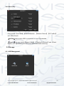
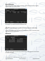
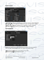
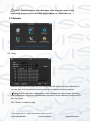
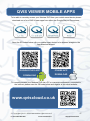
4/8/16 Channel Full Realtime 960H DVR User’s Manual V1.0 12 / 2013 Lo-Call 1890 866 900 www.cctvireland.ie [email protected] © Copyright Qvis ®. All documentation rights reserved. Lo-Call 1890 866 900 www.cctvireland.ie i [email protected] TABLE OF CONTENTS 1 FEATURES AND SPECIFICATIONS .............................................................. 1 1.1 Product Overview ............................................................................................................................ 1 1.2 Features ........................................................................................................................................... 1 1.3 Installation ....................................................................................................................................... 3 1.3.1 Unpacking Inspection ................................................................................................................ 3 1.3.2 Wiring Installation ...................................................................................................................... 3 1.4 The Mouse ....................................................................................................................................... 3 1.5 The Input Method ............................................................................................................................ 4 1.6 Power On/Off ................................................................................................................................... 4 1.6.1 Power On ................................................................................................................................... 4 1.6.2 Power Off ................................................................................................................................... 6 1.6.3 Power recovery .......................................................................................................................... 6 1.7 Icon ................................................................................................................................................... 6 1.7.1 The Screen Icons ....................................................................................................................... 6 1.7.2 Operation Icons ......................................................................................................................... 7 1.8 The Real-time Browser ................................................................................................................... 7 2 OPERATIONS GUIDE ............................................................................................ 8 2.1 The Right-click Menu ...................................................................................................................... 8 2.1.1 The Screen Switching ................................................................................................................ 8 2.1.2 Color setting ............................................................................................................................... 8 2.1.3 The Video Inquiry....................................................................................................................... 9 2.1.4 Alarm output .............................................................................................................................. 9 2.1.5 The Main Menu ........................................................................................................................ 10 2.2 The Introduction of the Main Menu ............................................................................................. 10 2.3 The Video Inquiry .......................................................................................................................... 11 2.4 Configuration ................................................................................................................................. 14 2.4.1 System ..................................................................................................................................... 14 2.4.2 Record ..................................................................................................................................... 15 2.4.3 Network .................................................................................................................................... 17 2.4.4 Alarm........................................................................................................................................ 20 2.4.5 Account .................................................................................................................................... 20 2.4.6 Abnormity ................................................................................................................................. 22 © Copyright Qvis ®. All documentation rights reserved. Lo-Call 1890 866 900 www.cctvireland.ie ii [email protected] 2.5 Storage ........................................................................................................................................... 22 2.5.1 HDD Management ................................................................................................................... 22 2.5.2 Backup ..................................................................................................................................... 24 2.6 Output............................................................................................................................................. 25 2.6.1 Display ..................................................................................................................................... 25 2.7 Maintain .......................................................................................................................................... 27 2.7.1 Log ........................................................................................................................................... 27 2.7.2 Version ..................................................................................................................................... 28 2.7.3 Default...................................................................................................................................... 28 2.7.4 BPS .......................................................................................................................................... 28 2.7.5 Auto Maintain ........................................................................................................................... 28 2.7.6 Online User .............................................................................................................................. 29 2.8 Shutdown ....................................................................................................................................... 29 3 WEB AND CLIENT ............................................................................................... 30 3.1 Web Operation ............................................................................................................................... 30 3.1.1 Network Connection ................................................................................................................ 30 3.1.2 The control installation and the user login logout .................................................................... 30 3.1.3 The Interface Of Web Operations ............................................................................................ 31 3.1.4 The Real-time Monitoring ........................................................................................................ 32 3.1.5 Configuration ........................................................................................................................... 33 3.1.6 Search Record ......................................................................................................................... 34 3.1.7 Alarm Configuration ................................................................................................................. 34 4 FUNCTIONS ......................................................................................................... 36 4.1 DDNS Function .............................................................................................................................. 36 4.1.1 Summary.................................................................................................................................. 36 4.1.2 NO-IP(www.no-ip.com) ....................................................................................................... 36 4.1.3 Dyndns DDNS(www.dyndns.com) ...................................................................................... 37 4.1.4 Test and verify DDNS .............................................................................................................. 37 4.2 Port Mapping ................................................................................................................................. 39 4.2.1 UPNP Function ........................................................................................................................ 39 4.2.2 Manual port mapping ............................................................................................................... 40 4.3 NTP function .................................................................................................................................. 40 4.3.1 Internet configuration ............................................................................................................... 40 4.3.2 Intranet Configuration .............................................................................................................. 41 4.4 Voice Intercom .............................................................................................................................. 41 4.4.1 Summarise ............................................................................................................................... 41 4.4.2 Configuration ........................................................................................................................... 42 © Copyright Qvis ®. All documentation rights reserved. Lo-Call 1890 866 900 www.cctvireland.ie iii [email protected] 4.5 HDD Redundancy .......................................................................................................................... 42 4.6 HDD S.M.A.R.T ............................................................................................................................... 43 5 COMMON FAULTS .............................................................................................. 45 © Copyright Qvis ®. All documentation rights reserved. Lo-Call 1890 866 900 www.cctvireland.ie iv [email protected] Welcome Thank you for purchasing the Medusa 4, 8 or 16 Channel Full Realtime 960H recording DVR. This user’s manual is designed to be a reference tool for the installation and operation of your system. Here you can find information about the corresponding DVR’s features and functions, as well as a detailed menu tree. Before installation and operation please read the following safeguards and warnings carefully! © Copyright Qvis ®. All documentation rights reserved. Lo-Call 1890 866 900 www.cctvireland.ie v [email protected] Important Safeguards and Warnings 1.Electrical safety All installation and operation here should conform to your local electrical safety codes. We assume no liability or responsibility for all the fires or electrical shock caused by improper handling or installation. 2.Transportation security Heavy stress, violent vibration or water splash are not allowed during transportation, storage and installation. 3.Installation Keep upwards. Handle with care. Do not apply power to the DVR before completing installation. Do not place objects on the DVR 4.Qualified engineers needed All the examination and repair work should be done by the qualified service engineers. We are not liable for any problems caused by unauthorized modifications or attempted repair. 5.Environment The DVR should be installed in a cool, dry place away from direct sunlight, inflammable, explosive substances and etc. This series product shall be transported, storage and used in the environment ranging from 0℃ to 55 ℃ 6. Accessories Be sure to use all the accessories recommended by manufacturer. Before installation, please open the package and check all the components are included. Contact your local retailer ASAP if something is broken in your package. 7. Lithium battery Improper battery use may result in fire, explosion, or personal injury! When replace the battery, please make sure you are using the same model! © Copyright Qvis ®. All documentation rights reserved. Lo-Call 1890 866 900 www.cctvireland.ie vi [email protected] 1 FEATURES AND SPECIFICATIONS 1.1 Product Overview This product is designed specifically for the use in the field of video surveillance and adopts H.264 video compression, hard disk recording, TCP/IP transmission and a Linux based OS in addition to some of the most advanced technology in the information technology industry. These elements help to produce a more stable, reliable and higher quality video image. The products support synchronised video, audio recording, playback, monitoring and the synchronisation of audio and video. The products support advanced control technology and strong network data transmission capacity. 1.2 Features Real-time monitoring Composite video signal interface and support TV, VGA or HDMI output simultaneously. Compression function Uses H.264 video compression standard and G.711 audio compression standard and has high definition, low code rate of the video coding to decrease the amount of data to save to HDD storage. Recording function Supports timing, alarm alerts, motion detection, SATA hard and local hard disks, DVR data backup and network backup. Video playback function You can search videos, within the local network, by using the playback interface. As well as this it supports multiple videos playback, fast playing, slow playing and frame-byframe playback. Video playback can be displayed the exact time of the incident using a graphical timeline to allow you to search for event footage much more efficiently. Camera control and alarm Remotely installed cameras can be controlled and various alarm devices can be connected to ensure that you know when an event has been detected. The DVR integrates Dynamic detection, video loss, video block, multiple alarm output and scene lighting control into its controller options. Communication Interface Equiped with USB 2.0 high-speed interface and an ESATA interface to allow for external video backup devices. There is also an option to store data on a remote server (cloud storage location) by connected the DVR to a local or wide area network by using the standard Ethernet interface port (plug and play). © Copyright Qvis ®. All documentation rights reserved. Lo-Call 1890 866 900 www.cctvireland.ie 1 [email protected] Network functions Supports: TCP / IP UDP RTP / RTSP DHCP PPPOE DDNS NTP Also supports real-time network monitoring, video playback, control and management functions. The built-in WEB Server will allow you to directly access the DVR through a web browser. Mode of operation You can operate by the DVR’s front panel or using a mouse. A simple, intuitive graphical interface is provided for intuitive operation. © Copyright Qvis ®. All documentation rights reserved. Lo-Call 1890 866 900 www.cctvireland.ie 2 [email protected] 1.3 Installation 1.3.1 Unpacking Inspection When you receive the product, check according to the packing list in the box. 1.3.2 Wiring Installation Preparing for installation Prepare a camera, a display, video lines, network cables, a mouse, and kinds of power cord. Installation Steps: 1. Place the DVR on a flat horizontal position and connect the camera to the video input interface in the rear panel. 2. Connect the displayer to the video output. 3. Connect the network to the RJ45 interface. 4. Connect the Mouse to the USB interface found in either the front or rear panels. 5. Connect the power. Caution For an external alarm device or a PTZ, please refer to the relevant instructions. Connect the power line after all lines connected correctly. 1.4 The Mouse In addition to front the panel keys and remote control menu, the user can use a mouse to operate DVR. Insert the mouse interface into the USB interface. Left Click Left click to enter the right menu or the main interface. Left click to access the menu option. Perform the operational instructions of the control interface. Change the state of the checkbox or dynamic detection blocks. Pop up a drop-down list when left click. When using the PTZ 3D control, left drag the area to achieve regional enlarging or reducing. © Copyright Qvis ®. All documentation rights reserved. Lo-Call 1890 866 900 www.cctvireland.ie 3 [email protected] Double Click Double click to play video. Double click to make the screen full or exit. Right Click Right click to pop up the right menu in the real-time monitoring screen. Exit the current interface without saving. Turning Wheel Turn the mouse wheel to change the value in the digital box. Switch the option of the combination box. Scroll back and forth to achieve the zoom function of channels and PTZ 3D. Mouse Move Select controls of the current coordinates to move. Mouse Drag Select area to detect. Select area to shelter. Select zooming function of PTZ control. 1.5 The Input Method In the input box, you can select figures, symbols, English capitalization and the input of Chinese. Click the mouse to complete the input.”← “represents the backspace and “_ “represents a space. 1.6 Power On/Off 1.6.1 Power On Install the DVR correctly and the connect power. When the light comes on, the DVR will boot automatically. DVRs will detect the hardware when power on and the process will last about 20 Seconds. After the detection, the DVR will make a “Buzzing” sound and enter a multiscreen real-time video surveillance status mode. © Copyright Qvis ®. All documentation rights reserved. Lo-Call 1890 866 900 www.cctvireland.ie 4 [email protected] If the hard disk boot is not connected, the following interface will pop up. The real-time multi-screen mode view: NOTE: Power supply has to match with DVR, any other substitutes are not allowed. © Copyright Qvis ®. All documentation rights reserved. Lo-Call 1890 866 900 www.cctvireland.ie 5 [email protected] 1.6.2 Power Off 【Main Menu】→【shutdown】 NOTE: Change HDD after close the device. 1.6.3 Power recovery Reboot after an unexpected power shortage or forceful shutdown, the DVR will save the recorded footage before outage and return to the normal operation mode. 1.7 Icon 1.7.1 The Screen Icons :The channel is recording. :The video of the channel is lost. :Motion detection function is online. :The channel is currently in the monitoring and locked status. :Adjust the size of the logo of the local audio output. :Allow screens to perform a round of the Tour setup. © Copyright Qvis ®. All documentation rights reserved. Lo-Call 1890 866 900 www.cctvireland.ie 6 [email protected] 1.7.2 Operation Icons : Not selected. : Selected. : The drop - down button :Leave the interface. :Cancel the settings. :Set parameters. :Save parameters :Restore the factory settings. :Apply current settings to the system. :Copy current settings to other channels. :Enter the configuration interface. :Select and configure the processing operation triggered by video detection or alarm. 1.8 The Real-time Browser There are a date, a channel name, a record type icon and a alarm status icon in each real-time monitoring screen. Switch screens by the front panel, a remote control or a mouse. If screen prompts of external alarm, video loss, occlusion detection, dynamic detection, network connection and IP conflict is set, the following interface will pop up when the relevant alarm occurs. © Copyright Qvis ®. All documentation rights reserved. Lo-Call 1890 866 900 www.cctvireland.ie 7 [email protected] 2 OPERATIONS GUIDE 2.1 The Right-click Menu Enter the real-time browsing interface. Click the right button and pop up a menu as shown in the figure. The Right button menu: 2.1.1 The Screen Switching Users can choose single, four, nine or sixteen channel. 2.1.2 Color setting Adjust the specified screen (single screen) image color hue, brightness, contrast, saturation, gain and white-level parameters set two time periods according to the local environment difference between day and night for each adjustment period set, the device will automatically switch to the best video quality. © Copyright Qvis ®. All documentation rights reserved. Lo-Call 1890 866 900 www.cctvireland.ie 8 [email protected] 【Period】: Two periods can be set according to ambient light during the day and night, device will automatically switch configuration time. Need to select the Enable box. 【Hue】: Adjust according to image color cast. 【Brightness】: Visual image brightness, according to the environment, reduces or Increases the brightness of the image to try to make it clearer. 【Contrast】: Adjust the black and white of the image (the greater the ratio, the brighter the image). 【Saturation】: Image color purity, the greater the value, the images will become more colorful. NOTE: Different mode different function 2.1.3 The Video Inquiry Refer to Chapter 2.3. 2.1.4 Alarm output NOTE: the manual recording requires users have the highest priority. In the real-time monitoring screen, right click and select [record] to enter the following interface. 【Channels】The number of channels that are in alarm status. 【Schedule】Alarm output is in control of alarm configuration. 【Manual】Alarm output is on and the status is active. 【Stop】Alarm output is off and the status is inactive. 【Status】The current status of alarm output. © Copyright Qvis ®. All documentation rights reserved. Lo-Call 1890 866 900 www.cctvireland.ie 9 [email protected] 2.1.5 The Main Menu Left click in the real-time monitoring screen. Input a user name and a password. Default users: User Type Administrator User Hidden Name admin user default Default Password 123456 123456 default NOTE: security measures of the password: If a wrong password is inputted three times, the device will produce an alarm sound. After incorrectly inputting the password in five times, the account will be locked. Please change the default password and the user name. Refer to Chapter 4.4.5 for more details. 2.2 The Introduction of the Main Menu 【Search】Search records by types, channels, time and playback records. 【Configuration】Include system, record, network, abnormity, alarm, account. 【Storage】HDD management and backup 【Output】PTZ, alarm output, serial and display. © Copyright Qvis ®. All documentation rights reserved. Lo-Call 1890 866 900 www.cctvireland.ie 10 [email protected] 【Maintain】Display log information, version information, stream statistics, and online user and set the factory default, automatic maintenance. 【Shutdown】Log off from the user menu, turn off the machine, restart the system, and switch user and other operations. 2.3 The Video Inquiry In real-time monitoring screen, right click and select【search】to enter the searching interface. © Copyright Qvis ®. All documentation rights reserved. Lo-Call 1890 866 900 www.cctvireland.ie 11 [email protected] Record Search interface description: Index Type 1 Record 2 Choose the time Choose the channels 3 4 5 6 7 8 9 10 Description There are video and pictures types to select. The ‘Pictures’ feature (local inquiries picture) is not yet open, so it is grayed. Select the records’ time. Select channels desired to query records. It can achieve full-screen and Cycle playing, stopping / playing, pausing, fast playing, slow Playback controls playing and the previous/next frame on a suspended state. Choose searched recording mode, including Recoding mode whole, outside alarm, motive detection, whole alarm recording. Shows the status information of channels’ video The timeline of recording within one day by using green, red, the videos yellow colours to highlight timeline. Synchronises all footage within the timeline to Synchronisation the same time. Displays status information of the function keys, Status which includes the fast-forward speed, slow speed and so on. List Display the list of recorded files. Time inquiries Search the records based on the starting time. © Copyright Qvis ®. All documentation rights reserved. Lo-Call 1890 866 900 www.cctvireland.ie 12 [email protected] 11 12 The channel number The list of records 13 Details of the documents 14 Backup Select the channel number. 128 video records can be shown in the searching list. Choose file(s) and press enter or double click mouse to view record. File type: R—normal record, A—alarm record; M—motion detection record. Display the start time, the end time, and the size of the video file. Tick to choose backup file in file list box, click backup button,cancel backup file ---click “√”from backup menu “√”. Playback Control: Key Video playback: Fast-forward button Video playback : Slow key Play/pause►/ Description Under playback mode, whilst pressing this key, you can get a variety of fast cycle switching speeds; the fast-forward button can be used as slow-release button or a reverse switch key. Under playback mode, whilst pressing this key, switch through this in a cycle. Supports a variety of slowrelease rates. The slow release button can be used as fast-forward button or a reverse switch key. Remark Actual play rate based on version Play/pause switch when in slow-play. Backward: Backward key Single left click backward key. Manual single frame playback Single frame playback by clicking │and│when common playback is paused. To play in reverse; single click again to stop normal playback. Then click rewind or the single-frame playback function, press the play button ►/ to enter the normal playback . NOTE: The player playback control bar shows file playback speed, channel, time, playback progress and other information. © Copyright Qvis ®. All documentation rights reserved. Lo-Call 1890 866 900 www.cctvireland.ie 13 [email protected] 2.4 Configuration User can get into configuration through the main menu, as seen here: 2.4.1 System Get into the system configuration: 【Time】Set the current time and save. 【Date Format】Modify the date format. 【Snapshot Interval】The snapshot interval time 【DST】Select the button and set the starting and ending time. 【Time Format】24 hr or 12 hr mode 【Language】 Select a language. 【Full HDD】When HDD is full, there are two options: “Overwrite” or “Stop recording”. If you select “Overwrite”, the DVR will overwrite the earliest files and continue recording. © Copyright Qvis ®. All documentation rights reserved. Lo-Call 1890 866 900 www.cctvireland.ie 14 [email protected] If you select “Stop recording”, the DVR will stop recording. 【Pack Duration】Set a length for each record. Default is 60 minutes. 【DVR No.】The default is 8. 【Video Standard】PAL/NTSC 【Auto Logout】This range is from 0 to 60 minutes. 2.4.2 Record Local channel 【Channel】Select a channel. 【Compression】H.264 【Resolution】The resolution of main stream can be either D1 or CIF. The channel extension stream resolution can support CIF or QCIF. Frame Rate: 1. PAL system: 25 frames / sec. 2. NTSC system: 30 frames / sec. 【Bit Rate】Constant Bit rate or Variable Bitrates. There are 6 levels for image quality in Variable Bit rate. 【Audio】Choose channels to record sound or not. 【Snapshot】You can set the capture mode, picture size, picture quality and capture frequency. Snapshot Mode: 1. Trigger capture: Capture picture when alarming. 2. Timing capture: Capture the pictures in channel enabled by setting a frequency. Picture Size: CIF. Picture Quality: 6 levels Snapshot Rate: Set a capture rate for the single channel. © Copyright Qvis ®. All documentation rights reserved. Lo-Call 1890 866 900 www.cctvireland.ie 15 [email protected] 【More Configuration】Enter the following interface. 【Channel Name Display】Choose to either show the channel name on the screen or not. 【Date Display】Show the date or not 【Channel Display】Drag channel title and save instantly. After quitting by right button, the position of channel title will not vary in displayer or in the monitor (varied position can be shown recorder and WEB interface). 【Time Display 】Drag time title and save instantly. After quitting by right button, the position of time title will not vary in displayer or in the monitor (varied position can be shown in the recorder and WEB interface). 【Video Cover】4 zones preview and display protect (you can adjust the privacy zone area). 【Preview】Set the masking zone. Masking zone is shown on the screen when displayed (no masking zone in web and record). 【Monitor】Set masking zone. Masking zones are shown in the screen when displaying or recording. Record plan © Copyright Qvis ®. All documentation rights reserved. Lo-Call 1890 866 900 www.cctvireland.ie 16 [email protected] 【Copy】Copy configuration of the current channel to other channels. 【Channel】Select a channel. It uses green, yellow and red colours to show motion detection and then carries out regular records correspondingly. 【Copy】Copy the settings to other channels. Click the set button to enter the following interface: 【Time 】Recording time.6 periods can be set every day. 【Normal】Normal record. 【Moving Detection】Moving detection. 2.4.3 Network Set the DVR network parameters in “Network” interface. The default IP address is 192.168.1.88 Base setting © Copyright Qvis ®. All documentation rights reserved. Lo-Call 1890 866 900 www.cctvireland.ie 17 [email protected] 【DHCP】Enable the DVR to obtain an IP address automatically. If this is enabled, the DVR will reboot and search for a DHCP server, and then assign a dynamic IP address. The dynamic IP address will be displayed in the menu. Enter a static IP address if there is no DHCP service available. If you are using the advanced feature PPPOE, then the IP/mask/gateway and DHCP are unable to be changed. 【IP Address】use()or input numbers to modify IP, then set 【subnet mask】 and 【default gateway】for this IP. 【First DNS Server】DNS server IP. 【Alternate DNS Server】DNS alternate IP 【Physical Address】physical address of current net port Advanced 【PPPOE】Enable PPPOE. Input PPPOE’s username and password provided by ISP. Operation: Using this feature, the DVR will automatically obtain a public IP address from your ISP. You can then visit the web interface of the DVR by typing this IP into Internet Explorer. 【DDNS】 Enable the DVR to register a DDNS hostname, which runs on a fixed IP address web client. 1. Select DDNS type(NO-IP DDNS, Dyndns DDNS, FNT DDNS and so on). 2. Input the registered server’s IP, port, username and password. 3. Once completed, you can login in the Web client by inputting the domain name in to your web browser. Refer to Chapter 6.1 about more details. 【NTP】 On/Off NTP. The network time protocol allows the DVR to sync with NTP server time automatically. © Copyright Qvis ®. All documentation rights reserved. Lo-Call 1890 866 900 www.cctvireland.ie 18 [email protected] Server IP: Input IP of NTP server. Port:The default port is 123. Update cycle: The interval time is between 1 to 65535 min. 【IP Filter】DVR authority management. If you enable the white list, only the filled IPs can be connected. This system supports a max of 64 IPs. 【Multicast】Transfer Capability Set: Enable the max connection and set network connection NUM, network connection NUM, transfer mode and LAN download. Port Set: 1. 2. 3. 4. TCP Port. Default: 8000. HTTP Port. Default: 80. UDP Port. Default: 8001. UPNP Port Mapping:Enable the function and make sure UPnP feature is enabled on the router. 【Email】Enable the function. Set the SMTP server’s port, username, password, the sender’s mailbox and receiver’s mailbox. 【FTP】Choose to upload records or images. 1. 2. 3. 4. 5. Set FTP server’s IP address and port (Default: 21). Create an account in FileZilla Server on the computer. Fill in the username, password and remote directory which have been created. Set file length, channel, time for recording, type and date and so on. Tick alarm, motion and general records or images to upload. 【Alarm Center】Set the platform software’s IP, port, and time for uploading the alarms. 【RTSP】The Real-time streaming protocol and the transmission of multimedia data protocol can be used to support the RTSP protocol player to play. 【3G】Supports 3G card in dial-up network to provide remote equipments access. © Copyright Qvis ®. All documentation rights reserved. Lo-Call 1890 866 900 www.cctvireland.ie 19 [email protected] Push Service The device supports the use of a push service and the smart phone mobile client. The interface is mainly used to open the push service. The current mobile client associated with the DVR, local real-time alarm information will also be sent to the phone even in the case that the mobile client is unopened. 2.4.4 Alarm Detect 【Motion detection】motion detection and alarm 【Zone setting】22*18 =396 zones mask 【Sensibility】6 grades 【Management】as same as local alarm 【Preview】alarm preview 【Video lose】detect video loses and alarm 2.4.5 Account NOTE: Group and user names can be from 1-6 characters in length. Valid characters include letter, numbers, and limited symbols: underline, subtraction sign, dot, you may not use a space as a leading or ending character. There is no limit to the number of groups or users. By default there are two different group levels: admin and user. User management determined upon two levels: the group and the user level. © Copyright Qvis ®. All documentation rights reserved. Lo-Call 1890 866 900 www.cctvireland.ie 20 [email protected] Group and user names cannot be duplicated, and each user can only belong to one group. 【Add users】Add group member information and set authorities. Default user: admin, user and default.The password of the first two usernames is 123456. “admin” has advanced authorities. “user” only has surveillance and playback authority. Hidden default: operate in password-less login mode, which you cannot delete. The DVR login name is automatic if no user logs in, user can revise limits of power then operate some without login. Enter【Add users】to input username, password and select group and reusable options. Reusable allows the account to be used by multiple logins. Users can only belong to one group. User rights cannot exceed group rights. 【Modify users】Modify existing group member information and authority. 【Add group】Add group and set group authorities. Set a group and authorise 60 items including control panel, shut down, live view, playback, record, record backup, PTZ control, account, system information, alarm in/out setting, system, search log, log delete, upgrade, operation authority, etc. 【Modify group】Modify existing groups information. 【Modify Password】Change the password. NOTE: Password can be up to 6 characters long. The account with management authority can change other users’ passwords. © Copyright Qvis ®. All documentation rights reserved. Lo-Call 1890 866 900 www.cctvireland.ie 21 [email protected] 2.4.6 Abnormity Firstly enable: 【No Disk】, 【Disk No Space】, 【Network Failure】, 【IP Conflict】 and 【Disk Error】. 【No Disk】alarms when HDD is not present or it can’t be detected. 【Process】You can choose【Alarm Output】, 【Display On Screen】 and 【Send Email】 and 【pushed to phone】to show abnormal events occurring. 2.5 Storage 2.5.1 HDD Management © Copyright Qvis ®. All documentation rights reserved. Lo-Call 1890 866 900 www.cctvireland.ie 22 [email protected] Base Configuration “Base Configuration” is the status & setup menu, and shows DVR storage capacity, available space and working status. 【Format】it is possible to format an individual HDD. NOTE: Hard disk format operation will result in the loss of video data. 【Set】to set HDD as read-write, read only or redundancy mode. In read only mode, video data cannot be over-written. HDD Record This menu screen will show the start and end times of each segment of video that is recorded to the HDD. © Copyright Qvis ®. All documentation rights reserved. Lo-Call 1890 866 900 www.cctvireland.ie 23 [email protected] 2.5.2 Backup Connect an External USB device with the USB port to backup in the “Record Backup” menu. 【Detect】Identify external USB device and display the device information. 【Backup】Tick the external device and click【Backup】to enter the backup menu . Select the records’ starting and stopping times and click【Add】to add in the list. Click【Delete】to clear the file list. Tick the record you want and click【Start】to backup and display time remaining. 【Delete】delete all data in USB backup device NOTE: The 【Delete】operation will cause loss of permanent recorded data. © Copyright Qvis ®. All documentation rights reserved. Lo-Call 1890 866 900 www.cctvireland.ie 24 [email protected] 2.6 Output The following Error! Reference source not found. shows the peripheral management interface. 2.6.1 Display Display mode can set the unit's display. GUI 【Transparency】4 grades. 【Channel Name】Modify the channel name. Options available to tick: 【Time Display】,【Channel Display】and【Over Info】. © Copyright Qvis ®. All documentation rights reserved. Lo-Call 1890 866 900 www.cctvireland.ie 25 [email protected] Output Configure 【VGA Output】Select VGA resolution and refresh rate. Default is 1024×768@60Hz. 【TV Adjust】Adjust TV output area. Modify the image to the right size for monitor. 【VGATV Color Set】Adjust displayer’s hue, brightness, contrast, saturation 【TV Color Set】Adjust monitor or TV’s brightness, contrast, saturation Tour configuration Enable video display touring and interval between rotations. The time is within 5120s.The mode includes single screen, four, eight, nine, sixteen screen. 【Motion Tour Type】Set the motion detection tour mode. 【Alarm Tour Type】Set the alarm tour mode. © Copyright Qvis ®. All documentation rights reserved. Lo-Call 1890 866 900 www.cctvireland.ie 26 [email protected] NOTE: Shortcut Setting: click the button at the top right corner of the monitoring picture or press the Shift Key to switch, to control the tour. 2.7 Maintain 2.7.1 Log Select the type and time press the Find, the system will display the log in tabular form, you can also click the backup button to export the log backup to your computer. 【Type】System operation, configuration, data management, alarm event, recording, user management, log delete and document operation can be selected. Choose time to filter the log list. Click “Delete” to delete all logs. © Copyright Qvis ®. All documentation rights reserved. Lo-Call 1890 866 900 www.cctvireland.ie 27 [email protected] 2.7.2 Version 【Version】Show features, software version etc. 【upgrade】Connect a USB flash device which contains the upgrade firmware and click “Upgrade”. NOTE:Update may cause the startup failure. Please operate under professional direction. 2.7.3 Default 【Default】Restoring the default settings of the following parameters. NOTE:Menu transparencies, language, time format, video format, IP, user ID, are not restored. 2.7.4 BPS 【BPS】Show video’s size, data rate of each channel by wave form. NOTE:Estimated value just for reference 2.7.5 Auto Maintain 【Auto Maintain】Set auto maintenance items. © Copyright Qvis ®. All documentation rights reserved. Lo-Call 1890 866 900 www.cctvireland.ie 28 [email protected] 2.7.6 Online User 【On-line Users】Display the current online user’s IP. 2.8 Shutdown 【Menu Logout】Log out of the current user. 【Shutdown】Shutdown the DVR 【Restart System】Reboot the DVR © Copyright Qvis ®. All documentation rights reserved. Lo-Call 1890 866 900 www.cctvireland.ie 29 [email protected] 3 WEB AND CLIENT 3.1 Web Operation 3.1.1 Network Connection 1. Check B-Lamp on front panel, light indicates connection. 2. Set IP, subnet mask and gateway for computer and DVR. Please assign the same segment IP address without using the router, need to set the appropriate subnet mask and gateway with router. 3. To view the details of DVR network configuration please navigate to: 【Configuration】→【Network Setting】 4. Ensure the IP is correct and check whether the DVR is on the network by using the Windows command “ping” in the ‘CMD’ window. 3.1.2 The control installation and the user login logout Users can remotely access the DVR via Internet Explorer, assuming you have a working and correct network configuration. The following interface will pop up when you access the IP address in Internet Explorer. Login screen Install ActiveX: Right click and choose install. If installation is blocked by Windows, please add the IP as a trusted site or lower your Internet Explorer security settings to allow this. © Copyright Qvis ®. All documentation rights reserved. Lo-Call 1890 866 900 www.cctvireland.ie 30 [email protected] Install Control The following interface will popup when you input your username, password and click “Login”. Interface like Diagram 5-3 Web Interface when user login successfully. Click “Exit” to quit. 3.1.3 The Interface Of Web Operations WEB Interface Description: Index 1 Name Channel 2 Function key 3 Surveillance window 4 Image color & other saturation 5 PTZ control 6 Menu Description Channel selection Local playback: playback local record Open all: play live views in surveillance window Change window layout Image color: modify brightness, contrast and Other: set capture path, record download path and reboot PTZ control menu System configuration, record search, alarm setting, exit, etc. © Copyright Qvis ®. All documentation rights reserved. Lo-Call 1890 866 900 www.cctvireland.ie 31 [email protected] 3.1.4 The Real-time Monitoring Whilst in the WEB interface, select the focus window within the live window. The focus window has a light blue border. From the left channel column select channel, as shown in the following interface. Channel Choices Click on 2 areas in upper right corner and you can choose to open / close the channel of the main stream or secondary stream. Above the live video window the current DVR's IP and rate information is shown (please see image below). Stream information Lower left corner shows the current video channel name. Upper right corner shows the current video time information. Click “ ”(Lower left corner of the display window)to switch between single screen and multi-screen. Lower right corner of the display window will display the function keys, as the following interface (next page). © Copyright Qvis ®. All documentation rights reserved. Lo-Call 1890 866 900 www.cctvireland.ie 32 [email protected] Function Key Area zoom: Video images can be enlarged. Multi-screen switch: switch from single screen to multi-screen and vice versa. Local record: save and record video to a local HDD while in a live view. Set recording path in configuration. Capture: capture of the present channel, set the path in “other”. Sound: on/off sound. Off video: off the focus window video. 3.1.5 Configuration Access DVR’s local configuration menu by clicking the “System Setting” option, for further details please refer to:【Local operation guide】 Configuration © Copyright Qvis ®. All documentation rights reserved. Lo-Call 1890 866 900 www.cctvireland.ie 33 [email protected] 3.1.6 Search Record Click the “Search record” option to open the search interface, you can search and operate record, alarm, motion, local record. Search record By selecting the record type, start and end times, and click the check button, get a list of files on the DVR. Select the appropriate file and download can be played. Play Double click a search result to play in video window. Control the playing video by the control keys on the bottom. At this point, the bottom of the video window will display the video control buttons, where video playback can be controlled. Download: select a searched video to download to local. The download speed and percentage are displayed on the bottom of the screen. Searching 3.1.7 Alarm Configuration Click the 【Alarm】 to enter the alarm setup menu, users can set up and operate the alarm mode. © Copyright Qvis ®. All documentation rights reserved. Lo-Call 1890 866 900 www.cctvireland.ie 34 [email protected] Alarm configuration Choose a type of alarm on the menu. These options include; monitor video loss, motion detection, disk full, disk error, video mask and external alarm. Click 【Video Pop-up】, this opens the video loss, motion detection, hard disk full, hard disk failure, video block and video encoder alarm pop-up linkage. Click 【prompt】opens the prompt: When an alarm occurs in real-time monitoring it will make a popup alarm window appear in the menu. Click 【Sound Pop-up】, you can choose a pre-recorded alarm tone on the local hard drive when an alarm occurs, tone file in WAV format. © Copyright Qvis ®. All documentation rights reserved. Lo-Call 1890 866 900 www.cctvireland.ie 35 [email protected] 4 FUNCTIONS 4.1 DDNS Function 4.1.1 Summary Dynamic DNS is a type of system which points the internet domain name to the variable IP address. According to the rule of the internet domain name, the domain name must associate with the fixed IP address. The Dynamic DNS provides a fixed Name server for the dynamic domain, and then needs to guide the domain search to the IP address of dynamic user through the Name server, which can make the outside user connect to the dynamic user’s URL. The DDNS setup window 4.1.2 NO-IP(www.no-ip.com) Register Register new username at no-ip, click 【Create Account】. Create domain name, click 【Add a Host】. © Copyright Qvis ®. All documentation rights reserved. Lo-Call 1890 866 900 www.cctvireland.ie 36 [email protected] Embedded DVR Setting Open 【Main Menu】→【Management】→【Network】→【Advanced】→【DDNS】 →【Enable】 Name DDNS IP Port Domain name Username Password Configuration NO-IP DDNS dynupdate.noip.com 80 xxx.xxx.org xxx xxxxxx 4.1.3 Dyndns DDNS(www.dyndns.com) Register To login at the Dyndns website, you need to register an account. Click on the confirmation link, login the account, click 【Add Host Services】 at [My Services], set your own realm name, and then operate according to the procedure. Configure the Embedded DVR Open 【Main Menu】→【Management】→【Network】→【Advanced】→【DDNS】 →【Enable】 Name DDNS IP Port Domain name Username Password Configuration Dyndns DDNS Members.dyndns.org 80 xxx.xxx.com xxx xxxxxx 4.1.4 Test and verify DDNS After setting up the embedded DVR, please wait for a few minutes and the analysis records will be updated. Click ‘Operation’ in the Menu of computer, input “cmd”, click “OK” to open a window. See ‘cmd’ prompt image on the next page. © Copyright Qvis ®. All documentation rights reserved. Lo-Call 1890 866 900 www.cctvireland.ie 37 [email protected] ‘cmd’ prompt Input “ping+ Domain name” then presses Enter, shown in the image below: The computer will analyse the domain name which is set in the DVR and return to the current IP address, underlined in red in the image above. When the IP address corresponds to the embedded DVR’s IP address in the Public internet, it means the DDNS had been setup correctly. If they are not, please check the network connection of embedded DVR and DDNS information. © Copyright Qvis ®. All documentation rights reserved. Lo-Call 1890 866 900 www.cctvireland.ie 38 [email protected] 4.2 Port Mapping Port mapping will map a port, which is outside the web host’s IP address, to terminal workstations connected to the local network beyond the port. When the user connects to the port of the IP, the server will automatically map the request to the corresponding workstations inside the local network. With this function, we can map many ports of a workstation’s IP address to different workstations’ ports inside web. The port mapping can also have other special agent functions, like POP, SMTP, Telnet, etc. Theoretically, it can provide more than sixty thousand ports. For example, if we want to map a web server which has an IP address of 192.168.111.10, we just need to input the IP address and TCP port 80 into the port mapping chart of the router. There are two ways to map the port: UPnP function automatically map and modifies the router’s port mapping chart. 4.2.1 UPNP Function In order to get a connection to the Embedded DVR through the Public network, we need to set the Router to cross the NAT of Embedded DVR. UPnP can make the NAT cross automatically by the UPnP agreement of Embedded DVR, and you do not have to set the Router. NOTE: to initiate the UPnP Function, the router must support an enable UPnP Function. STEP 1: Connect the Router to the network, get to the Menu of the Router, set the Router, and enable the UPnP Function. Routers made by different manufacturers may have some differences, please refer to the specification carefully before setting the Router. STEP 2: Connect the Embedded DVR to the Router; the configuration will automatically gain the IP address or static IP. After setting up the IP, click the ‘Advanced’ option and get to the XXX, ports, multicast, etc. Choose ‘Enable’ at the 【UPnP port mapping】option. STEP 3: Enter into the Router management interface; detect the port if there is already a Port mapping. If there is, it shows the settings in the UPnP all completed. © Copyright Qvis ®. All documentation rights reserved. Lo-Call 1890 866 900 www.cctvireland.ie 39 [email protected] STEP 4: Input the IP address in Internet Explorer, and add port number of the Embedded DVR, for example: 155.157.12.227:81. If you want to enter via the Client Software then you will need to use the TCP port offered by the outer net. NOTE: if there are a few embedded DVRs that need to set the UPnP function, in order to avoid IP conflict, set the ports of embedded DVRs to different ports numbers. Otherwise, it will choose the embedded DVR port set preceded as the first choice. 4.2.2 Manual port mapping The first step Connect the Embedded DVR to the Router and set the static IP. The second step Log in to Router, enter into the configuration menu of Router, and set the options in the menu. Then get to port, set the IP distributed by the Embedded DVR, and set port mapping, add HTTP and TCP port into mapping list. The default access ports of the Embedded DVR include HTTP port 80 and TCP port 8000. If the ports are occupied by other devices, please modify the default port of the embedded DVR into the other vacant ports. The third step Input the public net IP address in Internet Explorer, and add the port number of the embedded DVR that you want to access after the IP, for example: http://155.157.12.227:81. If you want to access via the Client Software, you can use the outer net TCP port directly to do so. NOTICE: for detail configuration setting, please refer to the user manual of Router. 4.3 NTP function Enable NTP function; synchronise the time with both the DVR and GPS clock server, to ensure the accuracy of device time. 4.3.1 Internet configuration Go to the 【CONFIGURATION】→【NETWORK】, choose 【Advanced】, and then choose 【NTP】to set. © Copyright Qvis ®. All documentation rights reserved. Lo-Call 1890 866 900 www.cctvireland.ie 40 [email protected] After the device has accessed the Internet, the NTP server can use the standard NTP server to obtain the time. Input the IP address and domain name of relative server at NTP setting. Activate NTP, click to choose “Enable”. The range for changing the time is 1 to 65535 minutes. 4.3.2 Intranet Configuration If the DVR works whilst running with the intranet, users can set up a privately-owned server as clock source. The NTP address in DVR configuration will fill in privatelyowned NTP address that work. A Privately-owned NTP server can adopt standard NTP products, which means it can use PC workstations to check for the correct time. Please refer to instructions below when adopting a PC system as a NTP server. NTP Server Set Up under Windows 1. “Start” menu → “Run” (or Win+R), input “regedit” to get into REGEDIT. 2. Build a new key assignment of the DWORD Value below. 3. HKEY_LOCAL_MACHINE\SYSTEM\CurrentControlSet\Services\W32Time\P arameters registry sub key; 4. Change the value to 1, and save. 5. Restart the computer. 4.4 Voice Intercom 4.4.1 Summarise Embedded DVR Bidirectional Talk: user can talk to remote client software or Web via the DVR audio input and output ports. User can also listen to the voice from the Client Software and the WEB via the DVR audio output ports. There are two types of bidirectional talk; sharing and standalone. © Copyright Qvis ®. All documentation rights reserved. Lo-Call 1890 866 900 www.cctvireland.ie 41 [email protected] 4.4.2 Configuration Local configuration Connect a microphone to the MIC input port, connect loudspeaker to the audio output port. NOTE: local output needs active audio output device. Remote PC Configuration Connect microphone and loudspeaker to computer. Enable bidirectional talk in the IMS software or WEB. 4.5 HDD Redundancy HDD redundancy function can backup the recording file. Users can then retrieve files via the HDD redundancy if the main HDD damaged and so preventing lose of data. The hard disk redundancy function is found through the designated channel data double backup in the HDD, so the DVR needs a standalone HDD for the redundancy function. HDD redundancy configuration Open the main menu and enter into the storage configuration, choose one of the HDD as the redundancy HDD and select one to set. The redundancy HDD must be an independent HDD. User can set several HDDs as a redundancy HDD group. Once a HDD is assigned as redundancy HDD, the recording data can be saved in both the normal HDD and redundancy HDD. Data stored on the redundancy HDD should automatically cycle coverage. Cycle period depends on the recording data and the redundant HDD’s capacity. Channel redundancy configuration The user can choose which video channels to record to the redundancy backup HDD. Please go to 【Configuration】→【Record】, choose redundancy channel, check mark 【Redundancy】. NOTE: the data in channel turn off redundancy only is recorded in normal reading and writing HDD if the redundancy is not enabled. © Copyright Qvis ®. All documentation rights reserved. Lo-Call 1890 866 900 www.cctvireland.ie 42 [email protected] Retrieve HDD redundancy The user can retrieve the backup recording data from redundancy HDD when the RW HDD is damaged or data lost. Firstly, shut down DVR and remove damaged HDD, then restart DVR; Secondly, Get into 【Main menu】→【Storage】, set redundancy HDD as a reading and writing HDD, then it can be searched. 4.6 HDD S.M.A.R.T S.M.A.R.T (Self-Monitoring, Analysis and Reporting Technology) S.M.A.R.T HDD can analyse the head, disc, motor, circuit operation, history and default security values via the monitor instruction in HDD and surveillance software. An alarm will be sent to the user automatically when the value is outside the scope of a low alert security situation. Detection parameters of Seagate HDD for example are divided into seven: ID detection code, Attribute Description, Threshold, Attribute Value, Worst, Date, and Status. 1. ID detection code The ID detection code is not always the same, the manufacturer can use different ID code or increase/decrease its quantity according to the detected parameter’s quantity. For example: the ID detection code of WEASTERN DIGITAL’s product is “04”, the parameter is for Start/Stop Count, but the parameter has the same code as the Fujitsu’s product and means: “Number of times the spindle motor is activated”. 2. Attribute Description Attribute Description: name of detection item. Manufacturer can increase or decrease. Because the ATA standard updates constantly, sometimes there are maybe different models in same brand, but you must ensure that they are the same major test items specified in S.M.A.R.T. (although different manufacturers have specific naming convention, the essence of monitoring is the same). 1: Read Error Rate 2: Spin up Time 4: Start/Stop Count 5: Relocated Sector Count 7: Seek Error Rate 9: Power-on Hours Count 10: Spin up Retry Count 194: Power temperatures 195: ECC on the Fly count 197: Current Pending Sector Count © Copyright Qvis ®. All documentation rights reserved. Lo-Call 1890 866 900 www.cctvireland.ie 43 [email protected] 198: Disconnection beyond repair 199: CRC cyclic redundancy check 200: Write Error Count 3. Threshold It is specified by manufacturer calculated through a specific formula. If there is an attribute value lower than the threshold it means the HDD has become unreliable and the stored data is very easy to lose. Composition and size of reliable attribute values is different for different HDD. It should be noted that, the ATA standard only provides some SMART parameters; it does not provide a specific value. "Threshold" value is determined by manufacturers based on products’ features. Thus, results tested by manufacturer provided detection software are very different from testing software under Windows (such as AIDA32) 4. Attribute Value Attribute value is the maximum normal value; the general range is from 1 to 253. Typically, the maximum attribute value is 100 (for IBM, Quantum, and Fujitsu) or 253 (for Samsung). Of course, there are some exceptions, for example, some models produced by Western Digital have two different attribute values, and property value is set to 200 when in initial production, but after then it is changed into 100. 5. Worst Worst value is the largest non-normal value in HDD’s running. It is a value to calculate for HDD’s cumulative running. It is constantly refreshed according to running cycle, and very close to the threshold. Whether the HDD is normal by S.M.A.R.T analysis is based on the comparison with threshold. The maximum value appear when new HDD start to use, which would continue to decrease with the everyday use or error happen. Consequently, larger attribute values mean better quality and higher reliability; smaller values mean more possibility of failure increases. 6. Dates Actual values of HDD’s detection items, many items are cumulative values. 7. Status This shows the current status of every attribute on the HDD, after analysing and comparing the above attribute values by S.M.A.R.T. It is also important information to judge to see if the HDD is healthy or not. There are three statuses: Normal, Alarm and Error----which is closely related with Prefailure/advisory BIT. © Copyright Qvis ®. All documentation rights reserved. Lo-Call 1890 866 900 www.cctvireland.ie 44 [email protected] 5 COMMON FAULTS DVR startup failure or continuously reboots Possible reasons: 1. The system has been damaged from a bad DVR update. 2. There is a problem with the DVR main board, please contact supplier. 3. There is a HDD error. Replace faulty HDD. Remote control does not work 1. 2. 3. 4. Check for batteries in the remote control. Check batteries’ power level. Check if remote receiver is obscured. Check if the DVR’s address corresponds to the remote control address. DVR cannot control the PTZ camera Possible reasons: 1. RS-485 cable connection error, A, B ports are inversely connected; 2. PTZ decoder, protocol, baud rate, address are incorrect; 3. Parallelly connect a 120Ω resistor to resolve signal reflex caused by too many PTZs on the line. 4. The RS-485 ports in the DVR are defective. Blurred screen in preview mode Possible reasons: Please make sure your cameras match your video format selected in the General menu. E.g. camera is NTSC standard but the DVR is PAL standard, the preview would be blurred. Blurred screen in playback mode or failure to playback records Possible reasons: 1. Procedure error, reboot the DVR 2. HDD error, test or change out the HDD 3. DVR hardware failure, contact your local supplier © Copyright Qvis ®. All documentation rights reserved. Lo-Call 1890 866 900 www.cctvireland.ie 45 [email protected] When you can’t connect DVR through network 1. Check the physical network connection is correct. 2. Check the DVR network configuration parameters. 3. Check whether IP conflicts exist in network. Download recording can not be played Possible reasons: 1. Player installation error. 2. The USB or HDD device has an error. 3. Do not install graphic software later than DX8.1. Internet Explore Crash Close IE explore, enter into the tool bar: DO NOT CHECK IE tool bar © Copyright Qvis ®. All documentation rights reserved. Lo-Call 1890 866 900 www.cctvireland.ie 46 [email protected] QVIS VIEWER MOBILE APPS To be able to remotely access your Medusa DVR from your mobile smart device please download one of our QVIS Viewer apps from either the Google Play or iTune stores. Scan the QR codes below with you mobile smart device to be directed straight to the app download source: GOOGLE PLAY APP iTUNES APP DOWNLOAD DOWNLOAD To remotely access your Medusa DVR via a PC or computer workstation, connected to the internet, please scan the QR code below and register to our cloud website: www.qviscloud.co.uk © Copyright Qvis ®. All documentation rights reserved. Lo-Call 1890 866 900 www.cctvireland.ie 47 [email protected] For more information about our DVRs and available cameras & accessories, please visit our website: www.adata.co.uk Alternatively scan this QR code with your smart phone to be directed instantly to our website: Download our mobile apps to remotely operate your DVR on the move. © Copyright Qvis ®. All documentation rights reserved. Lo-Call 1890 866 900 www.cctvireland.ie 48 [email protected]