1
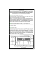
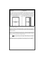
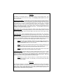
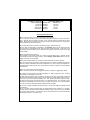
Inter-Dimensional Technologies, Inc. Better Technology...For A Better Life.™ EPC-MAG1 Electronic Pedestrian Counter User’s Manual May 2007 This User’s Manual is available on our website, www.IDTElectronics.com, in PDF format. 1 Table of Contents Section Introduction Features Options Theory of Operation Setup and Installation Operation Battery Life Frequently-Asked Questions Technical Information Contact Information 2 Page # 3 4 4 4 5 13 13 14 15 15 Introduction: The EPC-MAG1 is a microprocessor-controlled pedestrian counter that works with virtually all entrances that have at least one swinging door. Unlike our other electronic pedestrian counter devices that count pedestrians with infrared beam technology, this device actually counts the number of times that the door physically swings open. When the EPC-MAG1 might not best suit your needs: Because the EPC-MAG1 counts the number of times that the door(s) swings open, this device is only suited for certain types of establishments. If you have an establishment that needs to count every pedestrian that passes through the entrance (such as night clubs and bars for occupancy totals for fire codes), then the EPC-MAG1 may not best suit your needs. Another example where the EPC-MAG1 may not best suit your needs is if it is common for more than one unrelated pedestrian to enter while the door is opened (for example, one individual holding the door open for another). An example of this may be a convenience store during a busy time. If any of these scenarios apply, then one of our infrared pedestrian counters may better suit your needs. When the EPC-MAG1 might best suit your needs: If your establishment is not extremely busy or doesn’t have many unrelated parties entering on the same door swing, then this device may suit your needs. For example, the EPC-MAG1 would work well in a small gift shop. Further, the device may work well in environments such as furniture stores. Many times furniture stores do not typically have many unrelated pedestrians entering on the same door swing. For example, a husband and wife or an entire family (known in the retail industry as a “buying party”) usually enters on the same door swing. In these cases, most of the time, a manager or owner will want to count this buying party once, and not count each member of the buying party. Further, the EPC-MAG1 keeps a single running traffic total. It does not connect to a PC. If you feel as though you can benefit from advanced options such as analyzing the traffic by hour, day or other time interval, transmitting to a PC (and therefore to a network, if needed), wireless connection options, manager pager options* or CRM options*, then one of our other traffic counter models might better suit your needs. * - May be a future enhancement to our product line and may not currently be available. IMPORTANT NOTE: The EPC-MAG1 will only work with entrances that have doors that swing open and closed. Therefore, if you have an entrance that has no door, suchas those found in mall environments, then the EPC-MAG1 will not suit your needs. Further, if you have an entrance where a door is propped open all day, then the EPC-MAG1 will not suit your needs. In these situations, it is best to use one of our electronic pedestrian counters with infrared beams. 3 Features: State of the art microprocessor-controlled. Audible buzzer sounds when door is opened. Buzzer can be turned off if desired. Can still work with swinging doors that “bounce” shut or swing back and forth before coming to rest. The EPC-MAG1 will still work with doors that do not close perfectly or entirely. That is possibly because the magnetic sensors can sense the magnetic field of the magnet from as far as approximately 0.75” away. One or two doors can be sensed with the EPC-MAG1. This will accommodate a singleswinging door or double-swinging doors that are common to the retail and public establishments. Standard 9V battery power results in approximately one to two years of service, and in many cases even longer. See the “Battery Life” section for more information. Options: Alternative magnetic sensor/magnet pairs can be purchased from IDT. These alternatives include various colors, sensors and magnets with adhesive backing and sensors and magnets that can be flush-mounted in the doorjamb and door. Please contact us for more information. Theory of Operation: The magnetic sensors will send a signal to the EPC-MAG1 when it does not sense a magnetic field. The magnets, which are included, produce the magnetic field. Therefore, the magnetic sensor(s) is mounted to the wall or door molding, while the magnet is mounted to the edge of the door. When the door is opened, the magnet is moved away from the magnetic sensor and the sensor will sense the absence of the magnetic field. At that point, the magnetic sensor will send a signal through the wire to the EPC-MAG1. The EPC-MAG1 will then increment the total traffic count. Regardless of how long the door is opened, the EPC-MAG1 will only increment the count by a factor of one. Double swinging doors (two doors right next to each other) are very common in retail and public environments. In this case, one magnetic sensor/magnet pair will be used for each of the two doors, as shown in Diagram 4. Therefore, regardless of which of the two doors is opened, the EPC-MAG1 will still sense door swings on either door and increment the traffic count. What if both doors are opened? If one door is opened, and while it is opened, the second door is opened, the system will still only increment the traffic count by one. If your door “bounces” shut a number of times when released by an individual, the magnet (which should be attached to the door), might move away from the magnetic sensor enough such that the EPC-MAG1 may increment the count more than once. Further, if your door swings in and out repeatedly when rel eased by an individual before coming to rest, the EPCMAG1 may increment the count more than once. This is alleviated by setting jumper switches to add a delay so that the EPC-MAG1 will not count any more traffic until this delay has expired. See the Select additional delay step in the Setup and Installation section for more details. 4 Setup and Installation: The following tools will be needed to perform the installation. Phillips head screwdriver will be needed to screw screws into the wall to hold the EPC-MAG1, magnets and magnetic sensors. A drill may be needed to drill pilot holes for the screws. If you are mounting the equipment to a soft wood, such as pine, then pilot holes may not be needed. Pointy-nose pliers may be needed if you need to insert a bypass wire, which is required in one-door installations. Wire stripper/cutter tool may be needed to cut the wire to the proper length for a neat and tidy installation. Mini flat screwdriver will be needed to loosen and tighten the screw terminals that are on the circuit board inside the EPC-MAG1. You can also use this to adjust the contrast of the screen. The following is an overview of the following steps that will need to be performed to set up and install the EPC-MAG1: Step 1: Unpack and organize parts and verify that all are included. Step 2: Connect the spade connectors that are on the 2-conductor wire to the magnetic sensor(s). Step 3: Mount magnetic sensor/magnet pair(s). Step 4: Enable/disable Clear Traffic button. (Optional) Step 5: Select additional delay. (Optio nal) Step 6: Connect bypass wire to EPC-MAG1. (Optional) Step 7: Connect magnetic sensor(s) to EPC-MAG1 with 2-conductor wire. Step 8: Connect battery (and adjust screen contrast) Step 9: Screw lid onto EPC-MAG1 with the (4) M3 - 0.5 x 10mm machine screws. Step 10: Mount EPC-MAG1. Step 11: Install the cable ties. Step 1: Unpack and organize parts and verify that all are included. The following is included with the EPC-MAG1. Match the designation letters below to Photo 1 . A: (1) EPC -MAG1 electronic pedestrian counter B: (1) Plastic lid C: (4) M3 - 0.5 x 10mm machine screws to secure plastic lid to EPC -MAG1 D: (4) #8 x 0.5” sheet metal screws to secure EPC-MAG1 to wall E: (16) Cable ties F: (2) Magnetic sensors G: (2) Magnets H: (2) 8’, 2-conductor wire to connect magnetic sensors to EPC-MAG1 I: (8) Screws for magnets and magnetic sensors in small bags J: (2) Bypass wires (one extra included) NOTE: The cable ties and wire included in your order may look slightly different than what is shown in Photo 1. Step 2: Connect the spade connectors that are on the 2-conductor wire to the magnetic sensor (s). Loosen the screws on a magnetic sensor so that the spade connector can slide under the head of the screw as shown in Photo 2. There are two flat washers under each 5 screw terminal. Insert the wire’s spade connectors between each of the washers for optimum contact. You do not have to observe polarity when connecting these wires. This means that either of the two spade connectors can be connected to either of the two screws. Tighten the screws so that the spade connectors cannot be pulled out. Photo 2 Step 3: Mount magnetic sensor/magnet pair(s). If needed, drill pilot holes into the mounting surface onto which the magnetic sensor(s) will be installed. Similarly, if Photo 1 needed, drill pilot holes into the door onto which the magnet(s) will be installed. Mount the magnetic sensor(s) in a similar fashion to what is shown in Diagram 4 , using the screws that are included in the small bags. The magnetic sensors will not send a signal to the EPC-MAG1 until the magnet is approximately 0.75” from the magnet, or further. Therefore, do not mount the sensor and magnet too closely to the hinged side of the door because, even when the door is opened, the magnetic sensor may still sense the magnet field. Therefore, keep the sensor and the magnet as far away from the hinged side of the door as possible, without placing the two magnets too close to each other (when using both magnetic sensor/magnet pairs for two-door installations). Also, the position of the magnet relative to the magnetic sensor is very important. Please refer to Diagram 1 for ideal positioning. NOTE: You can leave the wire hanging from the magnetic sensor for now. In a future step, it will be cut to length, have its shielding stripped and have it secured with the wire ties. IMPORTANT NOTE: The next few steps have to do with setting jumpers inside the EPC-MAG1 and securing the wire by tightening the screw terminals inside the EPC-MAG1. Whenever you wish to do anything like this inside the EPC-MAG1, it is always best to do so with the battery disconnected, to ensure that the EPC-MAG1 is never damaged by accidentally shorting the product. Step 4: Enable/disable Clear Traf fic button. (Optional) Why? The EPC-MAG1 contains four buttons. One of these buttons is used to reset the traffic total to zero. However, this button can be disabled if desired, so that an employee cannot easily understate the traffic total by clearing the traffic total in the middle of the day, thereby raising his Close Ratio (number of sales divided by number of customers) and thus, appearing more suc- 6 cessful. See Clear Traffic Button in the Operations section for details on how to clear the traffic total to zero. How? There are three “jumpers” on the circuit board inside the EPC-MAG1. A jumper acts as a switch. These are not like a switch that will be turned on or off on a regular basis, but rather, a configuration switch that is set during the installation of the product. These switches are not normally adjusted after the initial setup of the equipment. One of these jumpers will allow the user to determine if the Clear Traffic button should be enabled or disabled. The factory setting of this position enables this button, as shown inDiagram 2a. If you would like to disable the Clear Traffic button, then pull off the jumper and reposition it as shown in Diagram 2b. Step 5: Select additional delay. (Optional) Why? The EPC-MAG1 will count the door swings as quickly as they can happen (although there is a slight delay when the buzzer is set to sound). When a pedestrian lets go of the door, most doors will swing closed and come immediately to rest. However, there are instances when swinging doors will bounce back open a few inches. Additionally, some swinging doors can swing back and forth until coming to rest. If this happens, the EPC-MAG1 will increment the count each time the magnetic sensor is separated from the magnet. This optional delay can alleviate this problem. How? There are three “jumpers” on the circuit board inside the EPC-MAG1. A jumper acts as a switch. These are not like a switch that will be turned on or off on a regular basis, but rather, a configuration switch that is set during the installation of the product. These switches are not normally adjusted after the initial setup of the equipment. 7 In order to suppress these false counts because of the door bouncing or swinging back and forth before coming to rest, we can add an additional delay before the unit will increment the count again. A delay of zero, two, ten or thirty seconds can be set by using two jumpers. The factory setting of these two jumpers is set to add no delay. Diagram 3 shows the configuration of the two jumpers for each of the four possible settings (0, 2, 10, 30 seconds). In order to adjust this delay, simply pull off the plastic jumpers and position them as needed. This means that, when the door is opened and closed, the count will be incremented and the delay period will begin. The EPC-MAG1 will not count any other door swings until this delay period has expired. NOTE: You will note in Diagram 3 that, when one jumper is set to zero and the other is set to the corresponding value (either 2 or 10), that value is what the delay will be set to, in seconds. However, when both jumpers are set, the delay is not 12 (2+10). Instead, we selected a more useful delay of 30 seconds. This is how we get the four possible delay values (0, 2, 10, 30). NOTE: The two-second delay is primarily intended to suppress false counts from a door that will bounce or swing back and forth before coming to rest. However, the 10and 30-second delays are primarily designed to help you determine how you want to count pedestrians and buying parties. For example, the 10 and 30 second delays can be used if you feel that a particular buying party, such as a husband and wife or a family, will enter on multiple door swings and you only want to count them as one buying party. Therefore, select the delay that suits your needs and environment best. Don’t use the 30-second delay if you feel that there’s too much of a chance that two unrelated parties will enter in that amount of time. If they do, then the second party will not be counted. If your environment very rarely has two unrelated parties entering within, say, a few minutes or longer, then the 30-second delay will probably not miss the second unrelated party because the two parties will be more than 30 seconds apart. IMPORTANT NOTE: Be sure not to set the delay period too long if you feel that there is a possibility that two or more unrelated parties may enter during that period. If the delay is too long, then the second of these two unrelated parties will not be counted. Step 6: Connect bypass wire to EPC-MAG1. (Optional) The EPC-MAG1 can monitor two doors by use of the two magnetic sensor/magnet pair (one 8 pair for each door). If only one door will be monitored, one of the magnetic sensor/magnet combos will not be used, as shown in Diagram 5b. Instead, a bypass wire, which is included, will be connected to one set of screw terminals, as shown in Photo 3. In order to connect the bypass wire, loosen the screws in the connectors shown in Photo 5 and insert the bypass wire into the connector from the outside, as shown in Photo 3. Next, tighten the screws from the inside so that the bypass wire is held firmly in place. Next, using the pointy nose pliers, gently tug on the bypass wire slightly to ensure that it is secure. Photo 3 Step 7: Connect magnetic sensor(s) to EPC-MAG1 with 2-conductor wire. Choose mounting location. Before connecting the magnetic sensor(s) to the EPC-MAG1, choose the locations where the EPC-MAG1, as well as the magnetic sensor(s), will be mounted. Once you choose the locations, you can determine how much wire will be needed to connect the system. When determining how much wire will be needed, attempt to position the wire exactly where it will be tied off with the included cable ties, to ensure a neat and professional installation. IMPORTANT NOTE: Be sure that the magnet for each magnetic sensor is further than approximately 0.75” from the other magnetic sensor. If the magnet from the opposite sensor is closer than this distance, when the door is opened and the magnet is pulled away from the sensor, the sensor will still sense the presence of the magnetic field of the other magnet and will not send a signal to the EPC-MAG1, resulting in the EPC-MAG1 not incrementing the traffic count. Further, you should make sure that there are no other magnetic fields near the magnetic sensor. What if the wire included is too long? If the wire is too long, cut it to length by cutting off the end that does not have the spade connectors. What if the wire included is not long enough? The spade connectors are used to make the connection to the magnetic sensors easier. If the length of wire that is included with the EPCMAG1 is not long enough and you need to use a longer wire, you don’t necessarily need to crimp spade connectors on the end of the wire. You can strip the shielding off of the end of the 9 wire and wrap the bare wire around the screw post before tightening the screw. However, if you have a crimping tool, and are able to do so, crimping two spade connectors, such as those found on the wire that was included, to the one end of each wire will ensure a better connection to the magnetic sensors. Before connecting the wire to the EPC-MAG1, you must first cut the wire to the proper length and then strip the shielding off the end of the wire so that it can make contact with the screw terminals inside the EPC-MAG1. Typically, ¼” of shielding should be stripped off of the wire. The wire that connects the magnetic sensors to the EPC-MAG1 has two conductors. In order to connect the wire, loosen the screws in the connectors shown in Photo 5 and insert each of the two conductors of the wire into the connector from the outside, as shown in Photo 4. Next, tighten the screws from the inside so that the wire is held firmly in place. Next, gently tug on the wire to ensure that it is secure and will not fall out of the EPC-MAG1. Photo 4 Photo 5 10 Photo 6 IMPORTANT NOTE: The two conductors in each wire are stranded wire. It is very important to make sure that not even one strand of one of the conductors accidentally touches the other conductor. This will cause the unit to not count traffic when the door to that sensor is opened. Therefore, it is best to “twist” the wire with one’s fingers in order to get all strands together so that the wire can be inserted into the connector properly. Step 8: Connect battery (and adjust screen contrast). The standard factory battery connector for the EPC-MAG1 is for a 9V battery. Next, place a 9V battery (not included) in the EPC-MAG1 as shown in Photo 6. At this point, you can also make sure that the screen contrast is set to an acceptable level. You can do this by pressing the “View Traffic” button and observing the text on the screen. If it is not at an acceptable level, the screen contrast can be adjusted by adjusting the yellow screw on the circuit board that is encased in blue plastic. You can adjust the yellow screw and then press the “View Traffic” button and repeat this process until the screen contrast is acceptable. Step 9: Screw lid onto EPC-MAG1 with the (4) M3 - 0.5 x 10mm machine screws. This is done by screwing the screws into the f our brass housings, located in each corner of the box, as shown in Photo 6. Step 10: Mount EPC-MAG1. If needed, drill pilot holes into the mounting surface onto which the EPC-MAG1 will be installed. Mount the EPC-MAG1 by securing it to the wall, door molding or shelf with the (4) #8 x 0.5” sheet metal screws, in a similar manner to what is depicted in Diagram 4. These screws will secure the EPC-MAG1 to wood or most hollow metal doorframes common to retail establishments. If you have a unique mounting situation, such as a concrete wall, alternative fasteners other than the sheet metal screws may be needed. Consult a network installer, electrician or contractor if you are not sure how to mount the system securely. It is not required that the EPCMAG1 be mounted; however, it is highly recommended. 11 Step 11: Install the cable ties. There are 16 cable ties included with the EPC-MAG1. This would allow one for every foot of cable that was included. If you use less than 16 feet of cable, you can use less cable ties, or include more than one per foot. If you use more than 16 feet of cable, please contact us if you need more cable ties. The cable ties have adhesive tape on the back of each. Simply peel the paper backing off of each one to expose the adhesive and press the cable tie to the wall or surface where the wire will be run. Typically, the cable ties are placed along the edge of the doorframe or other molding, as opposed to running the wire in the middle of the wall. NOTE: If you do not wish to use cable ties with adhesive backing, we can supply you with cable ties that mount with a screw instead. Please contact us for more information. Congratulations, at this point, the installation should be complete. Next, refer to the Operation section, which will guide you through the features of the EPC -MAG1 and how to use them. 12 Operation: The display is not normally turned on. This is done in order to conserve battery power. However, the device will still count the door swings. See the Display Traffic button section below for more information. Resetting the EPC-MAG1. The EPC-MAG1 is designed with the idea that it will be powered on 24 hours per day and has no on/off power switch. If you believe that the EPC-MAG1 is not operating properly, insert one end of a straightened paperclip into the “Reset” hole. Gently press the paperclip until you feel the recessed reset button engage. Hold the button in for approximately two seconds or more and then release the button and remove the paperclip. The EPCMAG1 should display the firmware version when it resets. (Firmware is the program that is programmed on the microprocessor.) It will also beep twice. The EPC-MAG1 should now be counting door swings and operating properly. Display Traffic button. Pressing and releasing the “Display Traffic” button will display the traffic total for three seconds and the display will then turn off to conserve battery power. This is the traffic total since the last time that the EPC-MAG1 was reset with the “Clear Traffic” button, which is described next. Clear Traffic button. Insert a straightened paperclip into the “Clear Traffic” hole. Using the paperclip, press and hold the recessed button for approximately three seconds. This will reset the traffic total to zero. A short beep will sound after each of the first two seconds. Finally, after the third second, a third longer beep will sound. The traffic total will be cleared after this third beep is heard. The EPC-MAG1 will display “Total Deleted” and the display will then shut off. At that point, the EPC-MAG1 is ready to sense door swings again and start counting from zero. NOTE: This button can be disabled by selecting the correct setting of the jumper as described in the installation instructions above. See Select additional delay in the Setup and Installation section for more information. NOTE: At any point in time while the Clear Traffic button is being pressed, the user can stop pressing the button before the third beep, and the traffic total will not be deleted. However, after the third beep sounds, the traffic will be reset to zero. NOTE: The three beeps described in this Clear Traffic button section will be heard, even if the buzzer is set to not sound when the door is opened. Toggle Buzzer button. The EPC-MAG1 can sound its internal buzzer when a door is opened. However, there may be times or environments where the buzzer can be intrusive. In these cases, the buzzer can be turned off or on by pressing this button. Each time that the button is pressed, the display will turn on momentarily and display the status of the button. Even if the buzzer is turned off, the EPC-MAG1 will still count the door swings. NOTE: Even if you wish to turn the buzzer off, it is best to keep it turned on when installing and testing the system. This will allow you to hear the buzzer sound when the door(s) is opened. Battery Life: The battery life expectancy of the EPC-MAG1 will vary based on the number of times that the door is opened. Whether or not the buzzer is set to sound when the door opens is another m i portant factor. Below is a chart that can be used to give an estimate of battery life for various levels of activity. Many factors affect battery life, such as age of the battery, temperature, etc. Therefore, lease note that these are only estimates. 13 Number of Times the Estimated Battery Life Door is Opened Buzzer Off Buzzer On 50 per Day 100 per Day 250 per Day 1000 per Day 426 Days 423 Days 418 Days 389 Days 217 Days 146 Days 74 Days 21 Days Frequently-Asked Questions Q: How can we contact you for technical support or repair issues? A: You can either e-mail or call us at the contact information provided at the end of the document. Although there is typically very little, if any, technical support involved with the EPCMAG1, please keep in mind that we do charge an hourly technical support fee, currently $70/ hour and billed in six-minute increments. Q: The EPC-MAG1 does not seem to be working properly. What should I do? A: First, reset the EPC-MAG1 as described in the Operation section of the manual and then test the system by opening/closing the door(s) and then viewing the traffic. If this does not fix the problem, replace the battery. If this does not fix the problem, contact us so that we can help fix the problem. Q: Why is the display not turned on? A: The display is not normally turned on in order to conserve battery power. However, the device will still count the door swings correctly. See the Display Traffic button option in the Operation section for more information. Q: Why does the EPC-MAG1 not increment the traffic total when the door is opened? A: If you are only using one magnetic sensor/magnet pair, then make sure that the bypass wire, which is included, is installed in the unused screw terminal. If you are using both magnetic sensor/magnet pairs, make sure that none of the strands of the wire is crossing over to the adjacent screw terminal. Q: Can the volume of the buzzer be adjusted? A: No. However, the buzzer can be toggled off and on by using the “Toggle Buzzer” button. Q: I need to use a longer wire than what is supplied, or I need to replace the wire. Are there specifications for what type of wire to use? A: While there are various types and sizes of wire that can be used, we strongly recommend two-conductor stranded wire with a gauge size of between 16 and 22 AWG. Feel free to contact us if you are not sure about what wire to use. Also, please note that the longer the cable, the larger the gauge size of the wire should be. The specified range of 16 to 22 AWG is given with the idea in mind that the wire will not be much longer than ten feet. If it is, please contact us so we can make sure that the unit will operate correctly and safely. Q: We have a unique installation with special needs. Can we order different magnetic sensors and magnets? A: Yes. We have access to special colors, as well as different types of sensors. For example, we have access to sensors that have adhesive backing on them if you do not want to drill holes into the door and doorframe. We also have access to sensors that can be flush-mounted into the doorjamb and door, for a cleaner look. 14 Technical Information Dimensions (WxLxH): Including Flanges: 4.335” x 2.205” x 1.532” Not Including Flanges: 3.339” x 2.205” x 1.532” Note: Flanges cannot be taken off. Weight: Without Battery: 3.5 ounces With Battery: 5.2 ounces Buzzer Amplitude: Typically 92 dbA Power Source: (1) Standard 9V Alkaline Battery Contact Information Mailing Address: Inter-Dimensional Technologies, Inc. P.O. Box 392 Hop Bottom, PA 18824 Shipping Address: Inter-Dimensional Technologies, Inc. 322 Greenwood Street Hop Bottom, PA 18824 Voice/Fax: 570.289.0989 E-Mail Address: [email protected] Website: www.IDTElectronics.com 15 © 2007, Inter-Dimensional Technologies, Inc. , All Rights Reserved 16