1
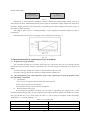
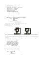
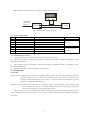
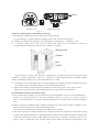
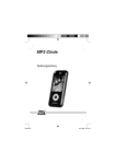
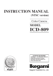
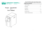
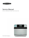
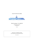
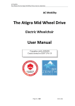
Content
1.
2.
3.
4.
5.
6.
7.
8.
9.
10.
11.
Safety guide ......................................................................................................................... 1
Main characteristic............................................................................................................... 1
Working principle ................................................................................................................ 1
Operational manual of explosion-proof type transmitter......................................................... 2
Frame-proof type transmitter before install and use notice points: .......................................... 3
Construction and technical parameter of liquid level transmitter............................................ 3
Debugging (WIDEPLUS -L series) .................................................................................... 6
Installation ......................................................................................................................... 7
Maintenance and Trouble shooting .................................................................................. 9
Ordering Information ....................................................................................................... 9
Type spectrum table for WIDE PLUS –L series liquid-level transmitter...................................10
1. Safety guide
Safety precautions
In order to ensure safety operation for WIDE PLUS –L series liquid level transmitter, which must abide the
following explanations:
Before install and use, please careful read this operational manual!
For short, the manual does not include the detail explanation of all product mode, also has not about every
particular of assemble, operation and maintenance. If want to know deeply or special question, then the
operational manual has not detail introduce part, please contact with us, and obtain necessary information.
Please pay attention to warn sign on the package! Iced measured medium can damage the sensor!
Only qualified or authorized persons are able to carry out installation, electric connection, operate and
maintenance of the transmitter.
Qualified personnel means who have experience in transmitters or similar devices and have related
certificates such as electric circuit, high voltage, corrosive medium. Such as have training, guide or
authorization for safety engineering standard operational maintain device or equipment of electric circuit, high
voltage and corrosive medium.
In order to your safe, please attention: when electric connect, it only to be able to use enough to absolute
tool.
In addition, it must abide related safety specification about electric install construction and operation. For
explosion-proof transmitter that should be has related specification and recommend standard with
explosion-proof. The transmitter may operate in the field of high voltage and corrosive medium; if handle is not
correct, then it is possible to cause serious person injury or material damage. When use in others country, which
must abide relate national specification.
2. Main characteristic
WIDE PLUS –L series liquid level transmitter adopts the sensor with international advanced level,
incorporate of high accurate electronic element under strict control of process. It uses dry-pressure measurement
technique without mediation liquid, full scope to technical advantage of the ceramic sensor and to make
WIDEPLUS –L series liquid transmitter have superior technical performance. Its anti-overload and anti-impulse
ability is strong; temperature offset is small, high stability, and have the very high measuring accuracy.
WIDE PLUS –L series liquid level transmitter have many output signal, range, process connection and
material. May widely use to petroleum, chemical industry, electrical power, metallurgy, pharmaceutical, food,
and other many industrial fields, and may be suitable for each field and medium. In particular, use to ideal
upgrade successor for traditional pressure meter and transmitter, is also ideal pressure measure instrument in
industrial automation field.
3. Working principle
Certain point static pressure in liquid is proportional to the distance between this point and its level, namely
P=ρ・g・h
In which
P –measured pressure (stress)
ρ— medium density
g --- gravity acceleration
h --- height from measured point to level
Measured pressure is only relative to height from measured point to level whenρand g known.
WIDE PLUS-L series level transmitter makes use of the above principle to measure liquid level.
Note: Measured liquid container must be lead to atmosphere that is open type, cannot sealed. Otherwise,
measured result has not meaning.
- 1 -
Measurement system
WIDEPLUS-L
Liquid level transmitter
WP
digital display
Fig. 3-1
WIDEPLUS –L series liquid level transmitter combines with WP series digital display namely make up of
static liquid level meter. Measured liquid level pressure signal is transmitted to digital display from liquid level
transmitter. Display transforms into and indicates corresponding level value according to the specific gravity of
the medium and other parameter.
Select display please refers to < Intelligent display / control regulation instrument> sample and relative
technical file.
Relation between load resistance and supply power voltage shown as the fig. 3-2:
Load
resistance
work zone
Work voltage
Fig. 3-2
4. Operational manual of explosion-proof type transmitter
4.1
Explosion-proof type and mark
This transmitter divided into two kinds: frame-proof type and essence safe type, pass through national
named explosion-proof quality examine organization carry on check and get the explosion-proof certificate of
quality.
A. Frame -proof type: ExidIICT6 certificate of quality number CNEX 03.1088
B. Essence safe type: ExiaIICT6 certificate of quality number CNEX03.822
4.2
The classification, grade, and temperature group of the explosion-proof electrical equipment used
into explosibility environment
A.
Classification
I class: electrical equipment used to below will of the coalmine.
II class: Factory used electrical equipment
This transmitter belong to II class electrical equipment
B.
Grade and temperature group
II class electrical equipment according to its suit used to explosibility gas compound ratio of the
maximum examine safe gap ME— SG (for frame-proof type) and the minimum ignition current MIC (for essence
safe type) divided into A. B. C three grade (see table 1-1), and according to its highest surface temperature
divided into T1~T6 group (see table 1~2).
Table 1-1 MESG grade table
Grade
MESG (mm)
MIC
IIA
MESG > 0.9
MIC>0.8
IIB
0.9≥MESG≥0.5
0.8≥MIC≥0.45
IIC
0.5>MESG
0.45>MIC
- 2 -
Table 1-2 Permissible electric apparatus surface temperature-grouping table
Temperature group
T1
T2
T3
T4
T5
T6
Permit the highest surface temperature (℃)
450
300
200
135
100
85
5. Frame -proof type transmitter before install and use notice points:
Transmitter strict according to GB3836.15~2000 (explosibility gas environment used electrical equipment
fifth part: Dangerous field electric install (except coal mine) relative item carry on install.
Frame -proof type transmitter when apply in dangerous field, the transmitter case cover must turn tighten, in
order to ensure apply safety must strict keep safe regulations, absolute not permit when make contact open the
transmitter cover.
When install the frame-proof type transmitter, must ensure cable lead out port with fine seal.
Transmitter external case must be grounding good.
After essence safe type transmitter must match used safety grid only can used in the dangerous field with
explosibility compound. Safety grid must correspond to GB3836.4~2000 “Explosibility gas environment used
electrical equipment fourth part essence safe “i” regulation, and pass through relative explosion-proof
department carry on check and get the explosion-proof certificate of quality, according to its operation manual
requirements carry on install.
E xi aⅡCT6 [Exia]ⅡCT6 Danger field
Safe field
+
P
P
I
+
Safe grid
-
-
POWER
24VDC
Fig:5-1
Ui = 28VDC, Ii =30 mA DC, Pi =0.84W, Ci = 0.04μF, Li = 0.1mH
Uo≤Vi, Io≤Ii, Po≤Pi, Co=Cp+Ci, Lo = Lp+Li
Uo, Io, Po, Co, Lo is essence-safe explosion-proof parameter of the safety grid; Cp, Lp is distributed
parameter of the connected cable.
In order to safety must distinguish the essence safe loop and the non-essence safe loop, and hold the
essence safe loop wiring and other electrical loop wiring separate run wire.
When inside element of the frame -proof type transmitter fail it need to repair or to replace, in principle
should undertake by manufacture factory. When user oneself repairs, must according to relative note matter,
concrete repair method please according to repair chapter and sections carry on. (Repair of the essence safe type
instrument only limit within described scope carry out, out of the scope repair must consult with manufacture
factory). After pass through checked and repaired only can renew put into revolve.
User may carry on the repair, only limit within the use common tool scope, but not allow use electric iron.
Repair must after the equipment stop power supplied and take off outside wiring, the faulty equipment take to
non-danger field, then can be carried on.
Prohibit reform and change standards
The product of the get explosion-proof certificate of quality not permit at will replace which for
explosion-proof performance influential parts or construction.
The power transformer supplied to safety grid must correspond to GB3836.4~2000 standard 8.1th item
requirement.
6. Construction and technical parameter of liquid level transmitter
6.1 Construction and technical parameter of WIDEPLUS –LD Direct Mount Type static pressure
liquid-level transmitter
- 3 -
Technical parameter
Power supply: 12.5V ~ 3 6 V DC
Output signal: 4 mA ~ 2 0 m A
2-wire system
Measuring Range: 0~100m (Max.)
Accuracy: 0.2 grade , 0.5 grade
Stability: <0.1%FS/year
Temperature: normal temperature
Medium: -20~70°C
Environment : -20~70°C
Storage: -20~80°C
Relative humidity: 0~95% RH
Material: Process connection: Stainless steel 1Cr18Ni9Ti
fluorine rubber
PTEE
Sealed weld
Membrane:
316 L stainless steel
Ceramic capacitance
Mode of process connection: flange (approves DN50 PN1.6 MPa)
Protection grade: IP65
K1 shell is IP67
Seal:
Dimensions (mm)
71
150
163
98
Fig. 6-1 Outline dimension of WIDEPLUS-LD Direct Mount type static pressure liquid-level transmitter
6 -2 Construction and technical parameter of WIDEPLUS -LC Cable Type static pressure liquid-level
transmitter
Power supply: 12.5 V~ 3 6 V D C
Output signal: 4~20mA
2- wire system
Measuring Range: 0~100m (Max.)
Accuracy: 0.2grade , 0.5 grade
Stabilit y: better than 0.1%FS/year
Atmosphere pressure: 86~108KPa
Temperature: normal temperature
Medium: -20~60°C
Environment : -20~70°C
Storage: -40~80°C
Material contacted with the medium
Housing: Stainless steel 1Cr18Ni9Ti
Seal:
fluorine rubber
PTEE
Sealed weld
- 4 -
Membrane:
316 L stainless steel
Ceramic capacitance
Material of guide gas cable: combination of polyethylene chloride and nitride rubber
Mode of process connection:
outer thread G1 1
2
flange (approves DN20, PN0.6)
Protection grade: the part of sensor is IP68, connection box is IP65 (K1 shell is IP67)
Dimensions (mm)
98
3
4
2
3
thread connection
1.transmitter shell
2.thread process connection
3.conducting gas cable
4.Probe
Φ27 or Φ42
Φ7.5
4
L( installation d imension )
1
118
G11/ 2
2
L( installation dimension )
1
150
98
Φ27 or Φ42
★ Note: the probe diameter of ceramic capacitance and diffusion silicon is respectively φ42 andφ27
6 -3 Construction and technical parameter of WIDEPLUS - LR bar type static pressure liquid-level
transmitter
Technical parameter
Power supply: 12.5 V~ 3 6 VDC
Output signal: 4~20mA
Measuring Range: 0~4m (Max.)
Accuracy: 0.2 grade , 0.5 grade
Stability: better than 0.1%FS/year
Permission Temperature: Standard temperature
Medium: -20~70°C
Atmosphere: -20~70°C
Storage: -40~80°C
Material contacted with the medium
Housing: Stainless steel 1Cr18Ni9Ti
Seal:
fluorine rubber
PTEE
Sealed weld
Membrane:
316 L stainless steel
Ceramic capacitance
Mode of process connection:
outer thread G1
flange (approves DN20, PN0.6)
- 5 -
Protection grade: the part of sensor is IP68, connection box is IP65 (K1 shell is IP67)
Dimensions (mm)
98
1
118
3
Φ16
4
2
G 1 /1 2
L ( nstallation dimension )
2
3
Φ16
Tread dimension
1.transmitter shell
2.thread process connection
3.stainless steel pipe
4.Probe
Φ27或 Φ42
4
L ( nstallation dimension )
1
150
98
flange connection
1.transmitter shell
2.flange
3.conducting gas cable
4.Probe
Φ 27或Φ42
★ Note: the probe diameter of ceramic capacitance and diffusion silicon is respectively φ42 and
φ27
7. Debugging (WIDEPLUS-L series )
7 -1 debugging
Cable, tube and direct mount type transmitters are calibrated in factory by “dry calibration”
according to medium density offered by user. Because the calibration condition is not same as
process condition, user needs re -calibration generally. Make level up to its span, and then set output
current to 20.000mA by turning Span Potentiometer. If the level cannot be makin g up to its span,
calibration can carry out according to below equation:
In=(h n /h max )*16+4
mA
In which: I n - output current relative to n point level (mA)
h n - n point level (m)
h max - Max. level (ie, span, m)
Pleas e refer to factory record for higher accuracy.
7 -2 Zero and range adjustment
Regarding to intrinsic safe transmitter, its Zero and range potentiometers are located in wiring
case. Slide the plate marking “Z” and “S” in which “Z” represents zero and “S” span.
Regarding to explosion-proof transmitter, potentiometers locate in the electrical circuit which is
in the housing. You will see the potentiometers after opening the housing.
7 -3 Schematic diagram for debugging wiring
A . Regulate system shown as the Fig. 7-1:
Standard
pressure
source
transmitter tester
+
Level +
transmitter
-
Fig. 7-1
Wiring Diagram
B. If process tester are not available, the test system can replace with a 24Vdc power, a 250Ω or a
- 6 -
50Ω standard resistance and a 41/2 digital voltage meter (Fig. 7-2)
4
Standard
pressure
source
1
2
digital voltimeter
-
+
50Ω
or
250 Ω
Level +
transmitter
-
Standard resistance
+
- 24VDC
Fig.7-2 Compound wiring diagram
7 -4 Tester requirements
No.
Tester Name
Measuring Range
1
2
Process Tester
Digital Pressure Meter
0-30mA, +/-0.05% with 24Vdc power
0-20KPa+/-0.05%FS
3
Digital Pressure Meter
0-2000KPa+/-0.05%FS
4
5
Piston Pressure Source
Pressure Source
0-60MPa+/-0.05%FS
Pneumatic setter, micro-pressure adjuster
6
24Vdc Power
24Vdc+/-1 0 %
7
8
Standard Resistance
Digital Voltage Meter
250Ω or 50Ω +/-0.01%
41/2 digital voltage meter, 0.01%
Remark
Optional
When Process Tester
unavailable
7 -5 Calibration procedure
A.
Connect pressure source and transmitter and seal the connection.
B.
Apply zero pressure to transmitter; output of transmitter should be 1.000V or 4.000mA. If not,
turn zero potentiometer.
C.
Apply span pressure to transmitter; output of transmitter should be 5.000V or 20.000mA. If not,
turn span potentiometer.
D.
Repeat step B and C until meeting the requirements.
8. Installation
8 -1 Wiring
Intrinsic safe: Signal terminals locate in a separate cabinet. Screw the back cap of housing; find five
terminals (See Fig. 8-1) in which two terminals are used for signal, the other two for
testing or connecting display meter. There is a diode between test terminals, so power
cannot be supplied to them directly.
Explosion -proof: Signal terminals locate in a separate cabinet. Screw the back cap of housing; find
f o u r terminals (See Fig. 8-1) in which middle two terminals are used for signal, the
other two for testing or connecting display meter.
There are two electric conduits on both sides of housing using for cable. Screw the nut to secure
cable. Conduit unused be sealed. There is a fixing for explosion-proof transmitter that be fixed after
operation.
- 7 -
1 2 3
S
4
Cable
5
- -+ +
Z
Intrinsic safe
Wire board
Explosion-proof
Fig. 8-1
8 -2 Basic requirements for installation and usage
A. Installation condition meets the requirements of this manual.
Avoid installing in violent vibration, heating source and corrosive atmosphere.
B. A holder is used for fixing housing. Avoid pressing or clamping the “ventilation” tube.
C. A separate cable (two cores, O.D 9~10mm) with metal screen grounded is used for
Explosion -proof transmitter. The electric conduit is as follows:
Sealing ring
Gasket
Nut
Cable
Fig. 8-2
Screw the nut to secure cable and meet requirements of explosion -proof and waterproof. Pay
attention to various disturbances: cable is in a line not in rolls; keeping distance from high voltage
cables; distributed capacitance <0.19uF and inductance <1.0mH.
D. Grounding: Screw grounding bolt to secure grounding wire. Make sure that grounding resistance
is less than 4 ohm. Grounding gasket be pressed under M10X16 b o l t .
E. Meet requirements of explosion -proof regulations. When safe grid is used, refer to User’s
Manual of safe grid and note cable length, distributed capacitance and inductance.
8 -3 Installation (Cable Type a n d bar Type)
A. Screw connection: Supply a G11/2 round nut with each transmitter. There are two installations: 1.
There is a G11/2 screw in site so screw the transmitter directly; 2. There is no a G11/2 screw in
site so a Ø50~60mm hole or a holder with Ø50~60mm hole is needed, then screw the transmitter
on it.
B. Flange connection: Default flange complies with GB 9119.6- 88 DN 50. If there is flanges in site
please provides flange size or standard to manufacturer.
Note: Direct mount transmitter flange meets GB 9119.6-88 DN50.
C. The sensor head can be submersed directly in liquid or with heavy material or with anchor fixing
on tank wall. Which installation is used depending on the practical conditions. Basic consideration
is that the sensing hole cann ot be blocked up by sediment; for example, to measure river level a
plate is used to smooth the level and the output signal. Make sure that the sensing hole is not
- 8 -
blocked when measuring paste level.
D. Do not alter or change elements , which may affect the explosive ability.
9. Maintenance and Trouble shooting
The instrument must carry on check regularly to its basic characteristic when operation,
adjusting zero. Replace fault elements; find trouble and shoot, to ensure the instrument ’
s operation is
normal and reliable, now the general trouble shooting method listed table explanation as follows:
Phenomenon
Cause
No output
Output=100%
or =0%
Shooting
Power voltage misused
Load resistance misused
Power voltage is not match with
load.
Power polarity
Output wire broken
Re- wire
Switch on
Measuring system un - correct
Check isolation meters, display
instrument and transmitters.
Zero, span and potentiometer
Un -correct or damage
Span coarse setting un -correct
Replace damage elements and
r e-calibrate.
Correct
Note: Please send transmitters to factory if above does not work.
10. Ordering Information
1 0 -1 Please note the followings when order explosion proof transmitter.
A. There are two kinds of transmitters for dangerous area use: explosion-proof and intrinsic safe.
User should select according to GB 3836.15-2000《 Electric Device Used in Explosive Gas
Environment No. 15 Section: Dangerous Location Electric Installation (Exclusive of Coal
Mine》 .
B. Determine the composition of inflammable or explosive medium, and then select the relative
proof group and class according to GB 3836.
C. The selected transmitter, which group and class should be higher than that of medium.
D. Temperature environment for explosion proof transmitter is -20~70°C.
E. Intrinsic safe transmit ter should use with related safe grid according to requirements of
explosion -proof or user’s manual. Safe grid made by our company is recommended.
1 0 -2 Please offer the followings when order:
A. Model
B. Standards, explosion-proof area
C. Process connection and its material
D. Sensor and its material
E. Installation size
Cable type: cable length L=( )m
Tube type: tube length L=( )m ( From flange face to sensor face)
F. Measuring range
G. Medium and its density
1 0 -3 Example
Capacitive cable level transmitter, explosion -proof, cable type, 316 screw G11/2.
Medium: water
Installation size: 5m
Measuring range: 4m
Ordering code: WIDEPLUS- LCD1TC1F2A5HG09
Medium: water
h =4m
L=5m
- 9 -
11. Type spectrum table for WIDE PLUS –L series liquid-level transmitter
11 -1 Type spectrum table
WIDE PLUS –L □ □ □
Model
□ □ □ □ □ □ □ □
Explanation
□□
C standard cable type (cable temperature ≤70℃)
C1 integrated
does not carry the connection box (note
Explosion-proof
1)
C2 integrated carries the connection box (note 1)
Pole type (note 1)
Direct-mounting type
Armored cable type G1 armored pipe for 304
(note 1)
G2 armored pipe for 316 SS
Standard type (no explosion-proof)
Isolated explosion type Exd IIBT6 or Exd IICT6 (K1
outline)
Intrinsic safety type ExibIICT6 or ExiaIICT6
316 L SS
304 SS
1Gr18Ni9Ti SS
Special requirement
Outer thread G11/2
Flange (note 2)
Special appointed
Membrane of diffusion A1: standard type
silicon
A2: super stable type
Ceramic capacitance membrane
Fluorine rubber
Nitrile rubber
PTEE (does not apply for diffusion silicon)
Full sealed weld (only used to diffusion silicon)
(4~20) mA DC two wire system
Special requirement
No field indication
0~100% linear display
LCD digital range display (liquid crystal)
LED digital range display (numeral tube)
0~100% LCD digital display
0~100% LED digital display
0.1 grade (note 3)
0.2 grade
0.5 grade
No counterpoise
Standard counterpoise (please provides flow rate,
density)
Special requirement
C
Type
R
D
G
S
Explosion-proof
rank
D
I
Material of
process
connection
Mode of process
connection
Membrane
material
Material of seal
element
Mode of signal
output
Display mode
1
2
3
9
T
F
Y
A
C
1F
2F
3F
4F
2
9
A
B
C
D
E
F
Accuracy grade
1
2
5
H
Counterpoise
Z
Y
Installation
dimension
Measuring scope
□
It only limited cable type and pole type (note 4)
□□
See the standard range table for WIDE PLUS –L series
universal pressure transmitter
Option gives an
WIDE PLUS –LCS1FA1F2A5H
example
● Note: approves K1 outline
● Notice to the order: density of liquid medium ( ), temperature ( )
The range of liquid level h = ( )m
- 10 -
Cable type: cable length L = ( ) m
Pole type: insert depth L = ( ) m (distance from the probe to flange)
● Note 1: The integration is that mode for which adopts import the sensor with stainless steel isolation
membrane and high-performance special amplification circuit be directly packed in the probe.
● Note 2: cable and pole type liquid-level flange approves DN 20 PN 0.6 MPa, direct-mounted
liquid-level flange approves DN 50 PN 1.6 MPa, threaded type approves the thread is G1 1/2, special
demand please noted it when ordering.
● Note 3: 0.1 grade precision can be realized only if it should be employed the membrane material of
super stable diffusion silicon (A2).
● Note 4: Installation dimension used in the cable and pole transmitter, if measuring range of well
water-level is 10 m, installation dimension is 11 m, then extra 1 m use to installation regulating, actual
measurement is 10 m and does not notice. Cable type approves height regulation is 1 m pole type users
should be detail noted the installation dimension.
● Note: Guide gas cable of cable liquid-level transmitter adopts high-performance environmental
protection material such as import abrasion-proof, weak acid-proof (concentration), anti-low tem
perature, and may apply to food, medicine and other survey field.
11-2.WIDPLUS series pressure transmitter standard span table
Gauge
pressure code
Measure
scope
Range
Capacitance
type overload
Diffusion
silicon
overload
Capacitance
type
Diffusion
silicon
G03
0-10KPa
4KPa-20KPa
0.6MPa
30KPa
√
×
G04
0-16KPa
6.4KPa-20KPa
0.6MPa
30KPa
√
√
G05
0-20KPa
8KPa-35KPa
0.6MPa
50KPa
√
√
G06
0-25KPa
10KPa-35KPa
11.0MPa
55KPa
√
√
G07
0-30KPa
12KPa-35KPa
1.0MPa
55KPa
√
√
G08
0-35KPa
14KPa-35KPa
1.0MPa
55KPa
√
√
G09
0-40KPa
16KPa-70KPa
1.0MPa
105KPa
√
√
G10
0-60KPa
24KPa-70KPa
1.0MPa
105KPa
√
√
G11
0-100KPa
40KPa-100KPa
1.0MPa
300KPa
√
√
G12
0-160KPa
64KPa-200KPa
1.8MPa
300KPa
√
√
0-200KPa
80KPa-200KPa
1.8MPa
300KPa
√
√
0-250KPa
100KPa-350KPa
2.5MPa
525KPa
√
√
G15
0-400KPa
160KPa-700KPa
2.5MPa
1.05MPa
√
√
G16
0-600KPa
240KPa-700KPa
4.0MPa
1.05MPa
√
√
0-1.0MPa
0.4MPa-10MPa
4.0MPa
1.5MPa
√
√
G13
G14
G17
NOTE: “×”,means do not provide; “√”means provide by standard range.
- 11 -