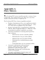
1
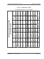
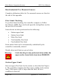
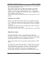
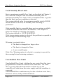
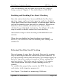
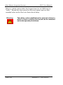
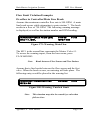
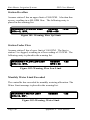
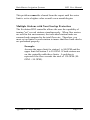
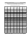
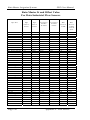
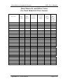
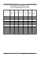
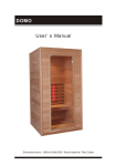
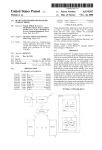
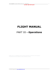
Rain Master Irrigation Systems
DX2 User Manual
Appendix A
Flow Meters
The Evolution DX2 series controller provides a variety of userconfigurable, flow-related features for either one or two flow
sensors, referred to as Flow #1 and Flow #2.
The Evolution DX2 flow features/capabilities include:
Display of instantaneous flow rate in gallons per minute
(GPM) for Flow #1, Flow #2 and total (Flow #1 + Flow
#2). Flow rates are updated every ten seconds.
•
Display of monthly flow accumulations in gallons for
Flow #1, Flow #2 and total (Flow #1 + Flow #2). Flow
accumulation in gallons is updated every minute.
•
Automatic termination of watering based upon flow
limit violations:
o
Main line flow rate for controller (GPM)
o
Maximum flow rate per station (GPM)
o
Minimum flow rate per station (GPM)
o
Maximum flow accumulation per month
(gallons)
o
Unscheduled flow rate for controller (GPM)
•
Automatic condemnation and reporting of
stations violating flow limits. Warning
information is provided in the Field
Maintenance Activity and Troubleshooting
section of the manual.
•
Automatic establishment of station upper and
lower flow limits (learn mode).
Page 232
Appendix A: Flow Meters
Appendix: A
Flow Meters
•
Rain Master Irrigation Systems
DX2 User Manual
Flow Meter Operation Overview
In order to display flow rate and/or flow accumulation data:
a. Insure flow sensor/meter has been properly connected
Refer to Flow Sensor Installation Instructions
b. Establish the appropriate flow calibration criteria, see
"Flow Meter Offset and K Values
In order to establish flow limit checking either on a controller or
individual station basis, verify the following:
c. Steps a and b (above) have been performed.
d. Station Upper Limits have been established, see "Max
Flow Limit".
e. Station Lower Limits have been established, see "Flow
Limit" page or "Auto Limits".
f.
Main flow limits have been established, (see "Main
Flow".
g. Total Monthly Flow has been set, see "Flow Options".
h. Unscheduled Flow Limit has been defined; see
"Unscheduled Flow Limit".
i.
The upper and lower limit checking is enabled; see
"Enable/Disable Limit Checking".
j.
The appropriate flow limit check delay has been
established, see "Delay Limit".
k. Selection of either one or two flow meters, see
"Flow Meter Compare Limits".
Appendix A: Flow Meters
Page 233
Rain Master Irrigation Systems
DX2 User Manual
Flow Reading Accuracy
Since the Evolution DX2 controller has been designed to work
directly with flow sensors, the accuracy of the actual readings
are limited only by the flow sensor devices. Typical accuracy
values are approximately 1%.
Flow Meter Offset and K Values
Each flow meter installation must include entry of the "offset"
value and "K" values for proper calibration of the meter. Use the
following table to determine the appropriate values for your
installation.
Page 234
Appendix A: Flow Meters
Appendix A: Flow Meters
Bronze
Bronze
Bronze
24
0
370
834
483
104
Slip
Slip
Slip
Slip
NPT female
NPT female with
copper male
adapters
NPT female
NPT female
NPT female
Requires pipe saddle with 2 Inch
female NPT
PVC
PVC
PVC
PVC
Bronze
32
0
Bronze
BODY
CONNECTION
MATERIAL TYPE
27
See attached table RMIS
Part No. 500712
400 PSI
Varies, Call
Factory
3 to 40 Inches
FS-INSERT-B
3752
100 PSI @
68º F
40-500 GPM
4 Inch
FS-400
2268
20-300 GPM
3 Inch
FS-300
100 PSI @
68º F
10-200 GPM
2 Inch
FS-200
776
5-100 GPM
1 ½ Inch
FS-150
750
100 PSI @
68º F
16-160 GPM
2 ½ Inch
FS-B250
200 PSI
291
457
10-100 GPM
2 Inch
FS-B200
400 PSI
209
100 PSI @
68º F
4-80 GPM
1 ½ Inch
FS-B150
400 PSI
109
1021
3-60 GPM
1 ¼ Inch
FS-B125
400 PSI
MAXIMUM
OFFSET
K VALUE
WATER
VALUE
PRESSURE
200 PSI
2-40 GPM
1 Inch
FS-B100
PIPE
SUGGESTED
FLOW SENSOR
CONNECTIO OPERATING
MODEL NO.
N SIZE
RANGE
RAIN MASTER FLOW SENSORS
SELECTION CHART
Rain Master Irrigation Systems
DX2 User Manual
Table 3: Calibration Table
Tee Mounted Sensors – Flow Sensors
Page 235
Rain Master Irrigation Systems
DX2 User Manual
Data Industrial Tee Mounted Sensors
Complete calibration tables for Tee mounted sensors are listed at
the end of this appendix.
Flow Limit Checking
To perform limit checking, the controller computes a GallonPer-Minute (GPM) flow rate based upon the total gallons used in
the previous 60 seconds.
Limit checks are then performed on the following:
•
Station upper limit
•
Station lower limit
•
Main flow limit
•
Total monthly flow limit
•
Unscheduled flow limit
Each station limit can be automatically established by the
controller or manually entered.
Details about each limit are given below.
Warning:
Limit checking is only performed when either the
upper and/or lower limits have been ENABLED.
Station Upper Limit
Enter an upper flow limit for the station, as described in Chapter
4. The controller compares the flow meter reading to the station
limit. If the meter value is larger than the limit, an error
condition is detected.
Page 236
Appendix A: Flow Meters
Rain Master Irrigation Systems
DX2 User Manual
The suggested upper limit flow rate should be set to the nominal
flow rate for the station + 20%.
The system default value for upper station limit is 500 GPM.
Obtain the nominal flow rate from the controller display (see
Chapter 7, for the steps in displaying flow rate). You should
allow adequate "settling time" for the flow meter readings before
obtaining the nominal flow rate.
Upper station limits should be increased, if water pressure varies
greatly.
Station Lower Limit
Enter a lower flow limit for the station, as described in Chapter
4. The controller compares the flow meter reading to the station
limit. If the meter value is less than the limit, an error condition
is detected.
To detect a mis-adjusted valve or clogged line, enter a relatively
small (but non-zero) lower limit.
The system default value for lower station limit is 0 (zero) GPM.
Main Flow Limits
Enter the Main Flow Limit, as described in the Main Flow
procedure in Chapter 4. The controller compares the flow meter
reading to controller/main line station limit. If the meter value is
greater than the limit, an error condition is detected.
The system default value for controller/main line limits is 2000
GPM.
The Main Flow upper limit should be set higher than the total of
all simultaneously "on" stations. However, this limit should be
lower than the anticipated flow rate from a main line break.
In Flow Max systems, the total water consumption of all
participating controllers is calculated into the Main Flow limit.
Appendix A: Flow Meters
Page 237
Rain Master Irrigation Systems
DX2 User Manual
Total Monthly Flow Limit
Enter a maximum monthly flow limit, as described in Chapter 4.
The controller compares the accumulated monthly flow to
maximum monthly flow limit. If the accumulated flow is greater
than the limit, an error condition is detected.
The system default value for maximum monthly total is NONE.
When NONE is selected, no monthly flow checking is
performed.
If the monthly limit is exceeded, there are two options available,
STOP WATERING and GIVE WARNING. See Chapter 4:
Setup for details on selecting each option.
The system default is: GIVE WARNING.
If the stop watering option is selected, the problem is reported in
the warning list and watering stops.
Watering is restarted when:
• The limit is changed to a larger value
• The limit is changed to None
• A new month begins
If the Give Warning option is selected, a warning is reported in
the warning list and watering continues.
Unscheduled Flow Limit
Unscheduled Flow Limit is defined as any water flow that is not
programmed or under the control of the controller. If a water
flow is greater than the limit and no stations are on, the
controller will shut down the water supply until the condition is
corrected.
Unscheduled Flow conditions may be due to broken water lines,
defective valves, faulty solenoids and etc.
Page 238
Appendix A: Flow Meters
Rain Master Irrigation Systems
DX2 User Manual
The Unscheduled Flow procedure is given in the Controller
Setup section of Chapter 4. The default limit is 200 GPM.
Enabling and Disabling Flow Limit Checking
Once the station limits have been established, the flow limit
checking (upper and lower limits) may be enabled or disabled.
When upper limits have been enabled, all station upper limits as
well as the monthly water limit will be validated. When lower
limits have been enabled, all station lower limits will be
validated on an individual station basis. See Chapter 4 for the
steps to enable or disable station flow limit checking.
The default setting for limit checking is DISABLED for all
stations.
When they are disabled, no limit checking is performed.
However, the GPM flow and total monthly flow readings are
unaffected.
Delaying Flow Rate Limit Checking
Due to drainage of water lines, the initial flow rate for a station
may be much higher than the station steady state condition. To
prevent erroneous station fault detections, the controller delays a
period of time after a station is turned on before making flow
rate limit checks. This delay may be set from 1 to 6 minutes.
The system default for delay of limit checking is two (2)
minutes.
To establish the proper delay, monitor the GPM flow rate for
each station in the irrigation program (s).
See Chapter 7 for details on monitoring GPM rates.
Appendix A: Flow Meters
Page 239
Rain Master Irrigation Systems
DX2 User Manual
Observe which station takes the longest time for its GPM rate to
"settle." Round this time period to the next minute and use this
rounded value as the flow rate limit check delay.
Warning:
Page 240
This delay value establishes the amount of time in
which a main or station line break can be detected
and subsequently shutdown.
Appendix A: Flow Meters
Rain Master Irrigation Systems
DX2 User Manual
Limit Checking with Two Flow Meters
When two flow meters are used, you may select which meter is
used for limit checking. Alternately, you may check the total
flow from both meters.
See Chapter 4: Setup for details.
Flow Meter Reading
Procedure
To observe flow meter readings, from the base menu:
Step 1
Advance to the Measurements Options screen as
follows:
F1=Main Menu
F3=Status
F2=Measurements
|F1|=FLOW
|F2|=CURRENT
|F3|=MOISTURE |F4|=ET |F5|=RAIN/WIND |½|
Figure 175: Measurement Options
Step 2
Select F1=FLOW METER.
The meter flow readings for Flow #1 and Flow #2
are shown in Gallons-Per-Minute. Readings are
updated every 10 seconds.
Appendix A: Flow Meters
Page 241
Rain Master Irrigation Systems
FLOW #1 GPM=55
FLOW #2 GPM=150
DX2 User Manual
TOTAL GPM=205
|½|
Figure 176: Flow Meter Readings
Page 242
Appendix A: Flow Meters
Rain Master Irrigation Systems
DX2 User Manual
Reading Monthly Water Totals
Procedure
To read the monthly water totals, from the base menu:
Step 1
Advance to the Status Options screen as follows:
F1=Main Menu
F3=Status
|F1|=COMM STATUS
|F3|=WATER TOTAL
|F2|=MEASUREMENTS
|F4|=REVIEW ALL |½|
Figure 177: Status Options
Step 2
Select F3=WATER TOTAL then select
F1=TOTALS PAST MONTH.
FLOW #1 PAST
FLOW #2 PAST
G = 600
G = 300
TOTAL GPM=900
|½|
Figure 178: Water Total
The past month total gallons for Flow #1 and Flow
#2 are shown.
Step 3
Select F2=TOTALS PRESENT MONTH. The total
present month gallons for Flow #1 and Flow #2 are
shown.
To update the totals, press the Up Arrow key and
select F2 again.
Appendix A: Flow Meters
Page 243
Rain Master Irrigation Systems
DX2 User Manual
When a Flow Limit Violation is Detected
Upon detection of a flow limit violation, Evolution DX2
performs the following actions:
1. Terminate Irrigation
•
For a faulty station, immediate termination of
irrigation for that station. The program will
automatically advance to the next station in the
program.
•
If a main line fault is detected, immediate
termination of all irrigation programs. The
Normally Open (N.O.) Master Valve terminal is
energized with 24 VAC. Any and all future
automatic irrigation will not occur until this warning
is cleared from the controller.
•
If the monthly watering allocation has been
exceeded, immediate termination of all irrigation on
a per program basis occurs.
•
If an unscheduled flow condition is detected, the
Normally Open (N.O.) Master Valve terminal is
energized with 24 VAC. Any and all future
automatic irrigation will not occur until this warning
is cleared from the controller.
2. Entry of the problem in the Warning/Report list.
3. All faulty stations are added to a "condemned" station
list. No watering will occur until the problem is
corrected.
To remove a station from the condemned list, delete the problem
entry from the warning report, see Chapter 10.
Page 244
Appendix A: Flow Meters
Rain Master Irrigation Systems
DX2 User Manual
Flow Limit Violation Examples
Overflow in Controller/Main Line Break
Assume the maximum controller flow rate is 500 GPM. A main
line break occurs while attempting to water station 7. The break
results in a flow of 750 GPM. The following warning message
is displayed, as well as the station number and GPM reading.
WARNING = MAIN FLOW (MV)
STA = 7, MV1,
5-20-96
11:48
GPM = 750
Figure 179: Warning, Main Flow
The MV1 in the second line represents the Master Valve #1.
To access the warning report, from the base menu, press
F2=WARNING.
Note:
Break between Flow Sensor and First Station.
Assume that a line breaks between the flow sensor and the first
valve. When the break occurs, no watering will take place. The
following entry would be placed in the warning list.
WARNING = UNSCHED LIMIT
GPM = 65
05/20/96
12:05
Figure 180: Warning, Unsched Limit
Note:
This situation may also be caused by a valve that
fails to close.
Appendix A: Flow Meters
Page 245
Rain Master Irrigation Systems
DX2 User Manual
Station Overflow
Assume station 2 has an upper limit of 300 GPM. A broken line
occurs, resulting in a 400 GPM flow. The following entry is
placed in the warning list.
WARNING = FLOW UP LIMIT
STA = 2, MV1,
05/20/96
GPM = 400
12:05
Figure 181: Warning, Flow Up Limit
Station Under Flow
Assume station 2 has a lower limit of 100 GPM. The line to
station 2 is clogged, resulting in a flow reading of 53 GPM. The
following entry is placed in the warning list.
WARNING = FLOW LOW LIMIT
STA = 2, MV1,
05/20/96
GPM = 53
1:35
Figure 182: Warning, Flow Low Limit
Monthly Water Limit Exceeded
The controller has exceeded its monthly watering allocation. The
Water Limit message is placed in the warning list.
WARNING = WATER LIMIT
STA =3, MV1,
05/20/96
1:35
Figure 183: Warning, Water Limit
Page 246
Appendix A: Flow Meters
Rain Master Irrigation Systems
DX2 User Manual
This problem cannot be cleared from the report until the water
limit is set to a higher value or until a new month begins.
Multiple Stations with Non-Overlap Protection
The Evolution DX2 controller allows the user the capability of
turning "on" several stations simultaneously. When flow meters
are used in this environment, the individual station limits are
summed and compared to the total flow rate. Therefore, you
must set up limits for each station to insure that flow limit checks
are performed properly.
Example:
Assume the upper limit for station 1 is 80 GPM and the
upper limit for station 2 is 50 GPM. If both stations are
on, the controller adds these limits. A problem is
reported if the flow exceeds the total of 130 GPM (80
GPM + 50 GPM).
Appendix A: Flow Meters
Page 247
Rain Master Irrigation Systems
DX2 User Manual
Table 4: Rain Master K and Offset Value
Rain Master K and Offset Value For Data Industrial Flow Sensors
CALIBRATION TABLE – TEE MOUNTED SENSORS (Current Production)
Models) (Series: 228PV, 228 BR, 228 CB, 228 CS, 228SS, 250BR)
Data
Industrial
Model
Apparent
ID
Evolution
Satellite
K Value
Evolution
Satellite
Offset
Min
Design
Flow
(GPM)
Max
Design
Flow
(GPM)
228PV-1.5
228PV-2
228PV-3
228PV-4
1.50
1.94
4.02
5.15
457
776
2268
3752
0
104
483
834
5
10
20
40
100
200
300
500
228BR-2
228BR-2.5
1.99
2.52
750
1021
0
370
10
16
100
160
228CB-2
150 PSI Tee
400 PSI Tee
228CB-2.5
2.07
2.07
2.10
2.51
777
777
711
1021
199
199
167
265
12
12
12
16
120
120
120
160
228CS-2
2.07
767
199
12
120
228SS-2
1.99
750
0
10
100
250BR-0.5
250BR-0.75
250BR-1
250BR-1.25
250BR-1.5
None
None
1.05
1.38
1.61
92
119
109
209
291
8
64
27
32
24
0.8
1
2
3
4
8
10
40
60
80
Page 248
Appendix A: Flow Meters
Rain Master Irrigation Systems
DX2 User Manual
OBSOLETE OR OLDER MODEL FLOW SENSORS
(Series:
Data
Industrial
Model
220P-1
220P, 228B, 228CB, 250B, 228PF, 228PD, 228CS, 228SS, *IR220P, IR228B,
IR228CB, IR250B, IR228CS, IR228SS)
Apparent
ID
Evolution
Satellite
Offset
Min
Design
Flow
(GPM)
Max Design
Flow
(GPM)
Minimum
Recommended
Full Scale
(GPM)
70
25
2
20
5
505
107
8
180
40
744
273
13
250
50
2268
4191
483
975
35
65
700
1200
160
300
0.96/FM92D
1.50/FM92D
1.94/FM92D
70
26
2
20
5
505
107
8
180
40
744
273
13
250
50
228PF-1.5
228PF-2
228PF-3
228PF-4
228PF-6A
1.71
2.21
2.98
2.99
569
1075
1512
2814
279
185
841
1911
228B-2
1.99/FM92D
2.52
750
0
10
250
50
1022
370
16
400
75
2.07/FM92D
2.07/FM93A
2.10/FM91D
2.51
767
198
12
250
50
711
167
12
250
50
1021
265
16
400
75
228CS-2
2.07/FM92D, FM93A
767
198
12
250
50
228SS-2
1.99/FM92D
750
0
10
250
50
250B-1
1.05/FM93A
1.38/FM93A
1.61/FM93A
113
47
2
45
8
209
32
3
90
15
291
24
4
100
20
220P-1.5
220P-2
220P-3
220P-4A
220P-6A
228PD-1
228PD-1.5
228PD-2
228B-2.5
228CB-2
150 PSI
Tee
400 PSI
Tee
228CB-2.5
250B-1.25
250B-1.5
0.96/FM92D
1.50/FM92D
194/FM92D
4.02/Any
5.15/Any
Evolution
Satellite
K Value
Appendix A: Flow Meters
Page 249
Rain Master Irrigation Systems
DX2 User Manual
Rain Master K and Offset Value
For Data Industrial Flow Sensors
Pipe Size
Pipe
O.D. in
Inches
Pipe
I.D. in
Inches
Evolution
Satellite
K Value
Evolution
Satellite
Offset
Min.
Flow in
GPM
Min.
Flow in
GPM
for Full
Scale
3 inch Sch 10S
Std. Wt. Sch 40
Ex. Strong Sch 80
PVC Class 125
PVC Class 160
PVC Class 200
3.5
3.5
3.5
3.5
3.5
3.5
3.260
3.068
2.900
3.284
3.230
3.166
1368
1191
1053
1391
1338
1278
115
70
42
121
107
91
12
12
12
12
12
12
400
400
400
400
400
400
4 inch Sch 10S
Std. Wt. Sch 40
Ex. Strong Sch 80
PVC Class 125
PVC Class 160
PVC Class 200
4.5
4.5
4.5
4.5
4.5
4.5
4.260
4.026
3.826
4.224
4.072
4.072
2620
2277
2008
2565
2361
2342
592
489
354
577
554
525
20
20
20
20
20
20
600
600
600
600
600
600
5 inch 10S
Std. Wt. Sch 40
Ex. Strong Sch 80
5.563
5.50
5.50
5.295
5.047
4.813
4451
4006
3594
1044
932
829
30
30
30
900
900
900
6 inch 10S
Std. Wt. Sch 40
Ex. Strong Sch 80
PVC Class 125
PVC Class 160
PVC Class 200
6.625
6.5
6.5
6.625
6.625
6.625
6.357
6.065
5.761
6.217
6.115
5.993
6576
5890
5312
6239
5997
5752
1603
1419
1265
1509
1445
1381
50
50
50
50
50
50
1500
1500
1500
1500
1500
1500
8 inch Sch 10S
Sch 20
Sch 30
Std. Wt. Sch 40
Sch 60
Ex. Strong Sch 80
PVC Class 125
PVC Class 160
PVC Class 200
8.625
8.625
8.625
8.625
8.625
8.625
8.625
8.625
8.625
8.329
8.125
8.071
7.981
7.813
7.625
8.095
7.961
7.805
11989
11371
11210
10943
10453
9914
11281
10884
10429
3215
3018
2975
2884
2735
2566
2994
2868
2729
80
80
80
80
80
80
80
80
80
2500
2500
2500
2500
2500
2500
2500
2500
2500
Page 250
Appendix A: Flow Meters
Rain Master Irrigation Systems
DX2 User Manual
Rain Master K and Offset Value
For Data Industrial Flow Sensors
Pipe Size
Pipe
O.D. in
Inches
Pipe
I.D. in
Inches
Evolution
Satellite
K Value
Evolution
Satellite
Offset
Min.
Flow in
GPM
Min.
Flow in
GPM
for Full
Scale
10 inch Sch 10S
Sch 20
Sch 30
Std. Wt. Sch 40
Ex. Strong Sch
60
Sch 80
PVC Class 125
PVC Class 160
PVC Class 200
10.75
10.75
10.75
10.75
10.75
10.420
10.250
10.136
10.020
9.750
19163
18473
18037
17622
16657
5768
5509
5345
5187
4827
125
125
125
125
125
4000
4000
4000
4000
4000
10.75
10.75
10.75
10.75
9.564
10.088
9.924
9.728
16010
17863
17273
16580
4594
5276
5054
4804
125
125
125
125
4000
4000
4000
4000
12 inch 10S
Sch 20
Sch 30
Std. Wt. Sch 40S
Sch 40
Sch 60
Extra Strong
Sch 80
PVC Class 125
PVC Class 160
PVC Class 200
12.75
12.75
12.75
12.75
12.75
12.75
12.74
12.75
12.75
12.75
12.75
12.390
12.250
12.090
12.000
11.938
11.625
11.750
11.376
11.966
11.770
11.538
28566
27997
27122
26638
26309
24690
25328
23457
26457
25430
24254
9831
9556
9156
8943
8783
8057
8336
7523
8857
8394
7869
175
175
175
175
175
175
175
175
175
175
175
5000
5000
5000
5000
5000
5000
5000
5000
5000
5000
5000
14 inch 10S
Sch 20
Std. Wt. Sch 30
Sch 40
Sch 60
Extra Strong
Sch 80
14.00
14.00
14.00
14.00
14.00
14.00
14.00
13.500
13.375
13.250
13.124
12.814
13.00
12.50
33390
32819
32255
31694
30343
31149
29027
12242
11941
11645
11353
10699
9639
10041
200
200
200
200
200
200
200
6000
6000
6000
6000
6000
6000
6000
Appendix A: Flow Meters
Page 251
Rain Master Irrigation Systems
DX2 User Manual
Rain Master K and Offset Value
For Data Industrial Flow Sensors
Pipe Size
Pipe
O.D. in
Inches
Pipe
I.D. in
Inches
Evolution
Satellite
K Value
Evolution
Satellite
Offset
Min.
Flow in
GPM
Min.
Flow in
GPM
for Full
Scale
16 inch 10S
Sch 20
Std. Wt. Sch 30
Ex. Strong Sch
40
Sch 60
Sch 80
16.00
16.00
16.00
16.00
15.500
15.375
15.250
15.000
43473
42791
42115
40785
17937
17495
17100
16331
300
300
300
300
9000
9000
9000
9000
16.00
16.00
14.688
14.314
39163
37278
15388
14332
300
300
9000
9000
18 inch Sch
10S
Sch 20
Sch 30
Std. Wt.
Sch 40
Sch 60
Extra Strong
Sch 80
18.00
17.500
55348
25847
350
10000
18.00
18.00
18.00
18.00
18.00
18.00
18.00
17.375
17.124
17.250
16.876
16.500
17.000
16.126
54553
52979
53765
51451
49187
52211
46997
25271
24145
24705
23110
21632
23599
20140
350
350
350
350
350
350
350
10000
10000
10000
10000
10000
10000
10000
Page 252
Appendix A: Flow Meters
Rain Master Irrigation Systems
DX2 User Manual
Figure 184: Flow Sensor Installation
Appendix A: Flow Meters
Page 253