1
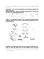
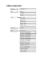
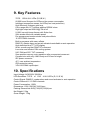
User Manual LED BEAM 7*15W 4in1 KEEP THIS MANUAL FOR FUTURE NEEDS 1. Unpacking Thank you for choosing our LED BEAM . For your safety, please read this manual before installing the device. This manual covers the important information on installation and applications. Please install and operate the fixture with following instructions. Meanwhile, please keep this manual well for future needs. This Fixture is made of a new type of high temperature strength of engineering plastics and cast aluminum casing with nice outlook. The fixture is designed and manufactured strictly following CE standards, complying with international standard DMX512 protocol. It’s available independently controlled and linkable with each other for operation. And it is applicable for large-scale live performances, theater, studio, nightclubs and discos. 4-IN-1 LEDs(RGBW) which features high brightness and stability. Please carefully unpack it when you receive the fixture and check whether it is damaged during the transportation. And please check whether the following items are included inside the box: Moving Head-----------------One Signal Cable------------------One Hanging Bracket------------One Power Cable-----------------One Safety Chain-----------------One User Manual-----------------One 1 2. Safety Instructions This device has left the factory in perfect condition. In order to maintain this condition and to ensure a safe operation, it is absolutely necessary for the user to follow the safety instructions and warning notes written in this user manual. If the device has been exposed to temperature changes due to environmental changes, do not switch it on immediately. The arising condensation could damage the device. Leave the device switched off until it has reached room temperature. This device falls under protection-class I. Therefore it is essential that the device be earthed. The electric connection must carry out by qualified person. The device shall only be used with rate voltage and frequency. Make sure that the available voltage is not higher than stated at the end of this manual. Make sure the power cord is never crimped or damaged by sharp edges. If this would be the case, replacement of the cable must be done by an authorized dealer. Always disconnect from the mains, when the device is not in use or before cleaning it. Only handle the power cord by the plug. Never pull out the plug by tugging the power cord. During initial start-up some smoke or smell may arise. This is a normal process and does not necessarily mean that the device is defective, it should decrease gradually. Please don't project the beam onto combustible substances. Fixtures cannot be installed on combustible substances, keep more than 50cm distance with wall for smooth air flow, so there should be no shelter for fans and ventilation for heat radiation. If the external flexible cable or cord of this luminaire is damaged, it shall be exclusively replaced by the manufacturer or his service agent or a similar qualified person in order to avoid a hazard. 22 3. Operation Instructions -The moving head is for wash effect for on-site decoration purpose. -Don’t turn on the fixture if it’s been through severe temperature difference like after transportation because it might damage the light due to the environment changes. So make sure to operate the fixture until it is in normal temperature. -This light should be keep away from strong shaking during any transportation or movement. -Don’t pull up the light by only the head, or it might cause damages to the mechanical parts. -Don’t expose the fixture in overheat, moisture or environment with too much dust when installing it. And don’t lay any power cables on the floor. Or it might cause electronic shock to the people. -Make sure the installation place is in good safety condition before installing the fixture. -Make sure to put the safety chain and check whether the screws are screwed properly when installing the fixture. -Make sure the lens are in good condition. It’s recommended to replace the units if there are any damages or severe scratch. -Make sure the fixture is operated by qualified personnel who knows the fixture before using. -Keep the original packages if any second shipment is needed. -Don’t try to change the fixtures without any instruction by the manufacturer or the appointed repairing agencies. -It is not in warranty range if there are any malfunctions from not following the user manual to operate or any illegal operation, like shock short circuit, electronic shock, lamp broke, etc. 4. Mounting and Installation Cautions: For added protection mount the fixtures in areas outside walking paths, seating areas, or in areas were the fixture might be reached by unauthorized personnel. Before mounting the fixture to any surface, make sure that the installation area can hold a minimum point load of 10 times the device’s weight. Fixture installation must always be secured with a secondary safety attachment, such as an appropriate safety cable. 3 Never stand directly below the device when mounting, removing, or servicing the fixture from a periodic safety inspection of all installation material and the fixture. If you lack these qualifications, do not attempt the installation yourself. Improper installation can result in bodily injury. Be sure to complete all rigging and installation procedures before connecting the main power cord to the appropriate wall outlet. Clamp Mounting: The LEDBEAM provides a unique mounting bracket assembly that integrates the bottom of the base, the included “Omega Bracket,” and the safety cable rigging point in one unit (see the illustration below). When mounting this fixture to truss be sure to secure an appropriately rated clamp to the included omega bracket using a M10 screw fitted through the center hole of the “omega bracket”. As an added safety measure be sure to attached at least one properly rated safety cable to the fixture using on of the safety cable rigging point integrated in the base assembly Regardless of the rigging option you choose for your LEDBEAM , always be sure to secure your fixture with a safety cable. The fixture provides a built-in rigging point for a safety cable on the hanging bracket as illustrated above. Be sure to only use the designated rigging point for the safety cable and never secure a safety cable to a carrying handle. 4 5. DMX-512 control connections Connect the provided XLR cable to the female 3-pin XLR output of your controller and the other side to the male 3-pin XLR input of the moving head. You can chain multiple When serial this fixture linking .The cable should be two core, screened cable with XLR input and output connectors. Please refer to the diagram below. DMX-512 connection with DMX terminator For installations where the DMX cable has to run a long distance or is in an electrically noisy environment, such as in a discotheque, it is recommended to use a DMX terminator. This helps in preventing corruption of the digital control signal by electrical noise. The DMX terminator is simply an XLR plug with a 120 Ω resistor connected between pins 2 and 3,which is then plugged into the output XLR socket of the last fixture in the chain. Please see illustrations below. 120Ω 2 3 1 PIN 3 PIN 2 5 6.Menu Operation ADDRESS SETTING(1-512) RUN DMX512 AUTO(1-8) SOUND TEST PAN(0-255) TILT(0-255) RED(0-255) GREEN(0-255) BLUE(0-255) WHILT(0-255) LANGUAGE ENGLISH Setup ID CODE(0-25) Pan Reverse(START/FINISH) Tilt Reverse (START/FINISH) Fader Delay(START/FINISH) Signal Link(START/FINISH) Code Wheel(START/FINISH) Temp Switch Set(START/FINISH) Temperature Set(50°- 120°) Screen Saver(RETENTION) Display Reverse(ON OFF) Factory Set(START/FINISH) RESET(START/FINISH) Pan Offset(ENTER) Tilt Offset(ENTER) 6 SYSTEM INFO TURN ON TIME(THIS TIME ON POWER) RUNNING TIME(TOTAL) SOFTWARE VERSION 屏幕校正(确认?) 返回 RUNNING MODE ADDRESS CODE TEMPERATURE(ACTUAL) MAIN MENU The user can control the cursor via button, with pressing “ENTER” to start setting. DMX Add Setting Submenu contains address setting, running mode, testing mode, language setting, advanced setting and system information, and the user can operate these modules according to soft button in the interface. 1) About address setting, the user should press ”YES/ENTER” to preserve address code and then return to main menu after setting done, or press “BACK” to cancel setting. 2) About running mode setting, the interface follows as picture 3,and it uses “√”to indicate the current mode(only one mode at a time).When the user choose DMX512 and AUTO MODE, you can press “ENTER” to set various DMX512 or auto modes. If the machine is set in DMX512,it also can be in SLAVE MODE at the same time. The mode can intelligently switch through different signal:DMX512 signal received,DMX512 MODE runs; host signal received, SLAVE MODE does. About AUTO MODE, the AUTO MODE is also HOST MODE at the same time. When the SOUND MODE runs, it is not HOST MODE. 3) TEST MODE. is a special mode that only if entering TEST interface, the user can operate this mode, and if quitting, the machine will restore the previous mode. In the TEST MODE, the user can adjust the location of Pan motor, Tilt motor and focus motor. TEST MODE has four-color brightness: RGBW which can be operated by 6th channel in DMX512. 4) LANGUAGE SETTING. Menu language can be set in English.(pic.5). 5) Setup ID CODE. It can be applied to 15 channel in DMX15 MODE. When the value of channel 15 is more than 9,only if ID code corresponds to the first two number of channel 15,other channel’s number can 7 be effective. Pan Reverse SETTING Tilt Reverse SETTINGY Fader Delay When PUTTER DELAY starts, the dimmer of console fader becomes soft. PUTTER DELAY can decide whether start or not through console Signal Link-After SIGNAL CONNECTION starts, it will cut light when console signal closes. Code Wheel-If it closes, encoder disk will fail, and cannot record Pan/Tilt correct position. When it recovers from error track, the reset will switch from Code Wheel- into maximum stroke reset. Temp Switch Set-Switch with temperature protection function Temperature Set-Protection temperature, with the function, if the machine measure actual temperature is beyond protection temperature, the brightness effect will fall half. Screen Saver. The user can set CLOSE,MODE1, MODE2.When machine closes, it won’t enter screen protection situation;MODE1,when display presentation finishes, it will be cleaned;MODE2,when machine enters display protection status, current address code will be display with large font. The user can touch the screen to cancel screen protection status, and return to main menu. Display Reverse can make the screen upside down180°. Factory Set is to set the parameter as the initial factory settings. RESET Pan Offset Tilt Offset, 5) System display related information about system ,as picture 6 , Turn-on time. The time is on electric power. RUNNING TIME, total lighting time. SOFTWARE VERSION. Program version currently in use. RUNNING MODE. The mode is running in current system. ADDRESS CODE TEMPERATURE - Temperature of light broad. 8 7. DMX 15 Channels Chanel Function Values Description 1 Dimmer 0-255 0-100% Linear dimmer from dark to bright 2 Red 0-255 0-100% red dimmer from dark to bright 3 Green 0-255 0-100% green dimmer from dark to bright 4 Blue 0-255 0-100% blue dimmer from dark to bright 5 White 0-255 0-100% white dimmer from dark to bright 6 Colors Choice 0-255 Colors changing effect 7 Pan 0-255 PAN Movement 8 Tilt 0-255 Tilt Movement 9 Pan Fine 0-255 Fine control of Pan movement 16Bit 10 Tilt Fine 0-255 Fine control of Tilt movement 16Bit 11 PAN/TILT Speed 0-255 Speed control of PAN/TILT (fast to slow) 0-15 Empty 16-95 Normal speed strobe 96-175 From fast to slowly 176-255 From slowly to fast 0-010 CH1-CH11 Activated 011-120 Colors jumping 121-180 Colors fading 181-209 Colors mixing and strobe 210-250 Auto 251-255 Sound control 0-255 Speed of macros(slow to fast) 12 13 Strobe Mode Macros and Sound Control 14 Macros Speed 15 No function 9 . DMX 11 Channels Chanel Function Values Description 1 Dimmer 0-255 0-100% Linear dimmer from dark to bright 2 Red 0-255 0-100% red dimmer from dark to bright 3 Green 0-255 0-100% green dimmer from dark to bright 4 Blue 0-255 0-100% blue dimmer from dark to bright 5 White 0-255 0-100% white dimmer from dark to bright 6 Colors Choice 0-255 Colors changing effect 7 Pan 0-255 PAN Movement 8 Tilt 0-255 Tilt Movement 9 Pan Fine 0-255 Fine control of Pan movement 16Bit 10 Tilt Fine 0-255 Fine control of Tilt movement 16Bit 11 PAN/TILT Speed 0-255 Speed control of PAN/TILT (fast to slow) 8. Photometric Data 10 9. Key Features 7PCS 15W 4-IN-1 LEDs (R,G,B,W ) 60,000 hours life span for LEDs and low power consumption Intelligent temperature sensor for LEDs(over heat protection) High efficiency 8 degree optic lens Color range with 16.7 millions additive RGBW colors High light output as 860LUX@ 7M at full 0-100% smooth linear dimmer with flicker free 20t/s strobe effect with variable speed Pre-programmed random strobe and pulse effects 11/15CH DMX channels Built-in programs with macro effects DMX512, master-slave and sound activated controllable or auto operation High definition blue TFT LCD display Quiet, smooth and fast PAN/TILT movement Low noise and efficient FAN cooling system 540° PAN and 250° TILT movement Scan position memory, auto reposition after unexpected movement Compact size with only 4.9KG body and 310mm in height IEC power connector 45℃ max ambient temperature IP20 protection rating 3-Pin XLR DMX input/output 10. Specifications Input Voltage: AC90-260V 50/60Hz LED Quantities: 7 PCS of 15W 4-IN-1 LEDs (R, G, B, W) Control Signal: DMX512, master-slave and sound activated or auto operation Control Channel:11/ 15 DMX channels Power Consumption: 120W Dimensions: 152(L)*265(W)*310(H)mm Packing Dimensions:260(L)*320(W)*335(H)mm Net Weight: 5.5kg Gross Weight: 7.5kg 11 11 11. Maintenance and Cleaning The following points have to be considered during the inspection: 1. All screws for installing the devices or parts of the device have to be tightly connected and must not be corroded. 2. There must not be any deformations on the housing, color lenses, fixations and installation spots (ceiling, suspension, trussing). 3. Mechanically moved parts must not show any traces of wearing and must not rotate with unbalances. 4. The electric power supply cables must not show any damage, material fatigue or sediments. Further instructions depending on the installation spot and usage have to be adhered by a skilled installer and any safety problems have to be removed. In order to make the lights in good condition and extend the life time, we suggest a regular cleaning to the lights. 1) Clean the inside and outside lens each week to avoid the weakness of the lights due to accumulation of dust. 2) Clean the fan each week. 3) A detailed electric check by approved electrical engineer each three month, make sure that the circuit contacts are in good condition, prevent the poor contact of circuit from overheating. We recommend a frequent cleaning of the device. Please use a moist, lint- free cloth. Never use alcohol or solvents. There are no serviceable parts inside the device. Please refer to the instructions under “Installation instructions”. Should you need any spare parts, please order genuine parts from your local dealer. 12