
1
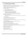
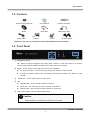
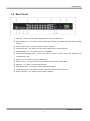
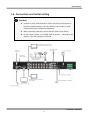
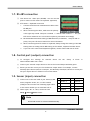
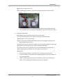
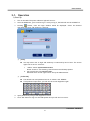
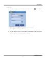
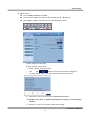
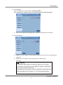
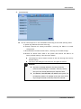
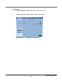
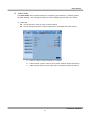
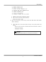
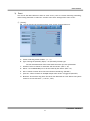
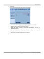
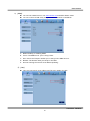
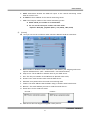
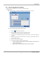
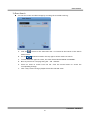
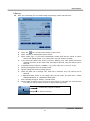
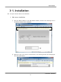
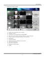
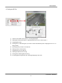
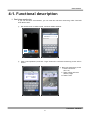
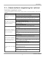
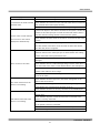
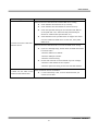
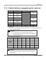
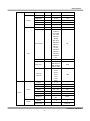
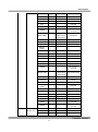
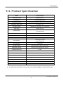
Rev. 1.1 (2010-07-22) USER’S MANUAL Swann DVR16-8900 H.264 Real-Time Standalone DVR User’s Manual Please read the safety precaution before using the product. MT16120810E H.264 REAL TIME DVR 0 USER’S MANUAL Safety Precautions Disconnect power to the DVR when Do not install the DVR in direct sunlight. connecting or disconnecting cables or Install the DVR in a cool and well ventilated accessing the rear panel. location. Don’t install the DVR in an area Exercise caution handling liquids around near heating devices. the DVR. Don’t place cups or bottles Don’t install the DVR in a location where it is Do not bend, twist or place heavy objects likely to fall. The power outlet the DVR uses must be grounded, and the voltage range must be detergents. Use a dry cloth or towel to within 10% of the rated voltage. Do not share the power outlet the DVR uses Do not install the DVR in areas with high with high-current devices (such as hair dryer humidity, dust or smoke. iron, refrigerator or heating device). When unplugging the power, hold the plug When replacing the battery, always replace and unplug slowly. Do not hold the plug with the same type of battery as the one with wet hands or connect the DVR to a provided. When disposing the battery, follow loose power outlet. the directions of the manufacturer, or the law Do not disassemble or reconfigure the as it applies in your locality. DVR. Don’t remove the casing except to Do not clean using liquids, soaps or remove dust from the DVR as necessary. Install the DVR on a sturdy, flat surface. containing liquids on or near the DVR. on your cables. Always use new, high quality hard drives. change the hard drive or backup battery. Older or damaged hard drives may lose There are no other user serviceable parts data. If this occurs, the DVR will show the inside. message “Error or Defective” indicating that Ensure there are no obvious dangers it cannot access information on the hard where you install the DVR. Check for drive. In the event this occurs, contact the moisture, damaged cables or wiring, hard drive manufacturer: many have data unstable surfaces and infrastructure and so recovery services available. on. Don’t install the DVR in any location where one or more dangerous elements is present. H.264 REAL TIME DVR 1 USER’S MANUAL CAUTION RISK OF ELECTRIC SHOCK. CAUTION! DO NOT OPEN. TO REDUCE THE RISK OF ELECTRIC SHOCK, DO NOT REMOVE COVER (OR BACK). NO USER-SERVICEABLE PARTS INSIDE. REFER SERVICING TO QUALIFIED SERVICE PERSONNEL. Explanation of Two Symbols The lightning flash with arrowhead symbol, within an equilateral triangle, is intended to alert the user to the presence of un-insulated “dangerous voltage” within the product’s enclosure that may be of sufficient magnitude to constitute a risk of electric shock to persons. The exclamation point within an equilateral triangle is intended to alert the user to the presence of important operating and maintenance (servicing) instructions in the literature accompanying the appliance. THE GRAPHIC SYMBOLS WITH SUPPLEMENTAL MARKING ARE ON THE BOTTOM OF THE SYSTEM. “WARNING – TO PREVENT FIRE OF SHOCK HAZARD, DO NOT EXPOSETHE UNIT TO RAIN OR MOISTURE” FCC CLASS A NOTICE This equipment has been tested and found to comply with the limits for a Class A digital device, pursuant to part 15 of the FCC Rules. These limits are designed to provide reasonable protection against harmful interference when the equipment is operated in a commercial environment. This equipment generates, uses, and can radiate radio frequency energy and, if not installed and used in accordance with the instruction manual, may cause harmful interference to radio communications. Operation of this equipment in a residential area is likely to cause harmful interference in which case the user will be required to correct the interference at his own expense. H.264 REAL TIME DVR 2 USER’S MANUAL Caution Please read the following precautions carefully before installing the product and follow the directions for installation. Don’t install the DVR in a location which has high levels of dust, moisture, smoke or other contaminants. Avoid locations which have high or fluctuating temperatures, and avoid direct sunlight. Do not install the product where the temperature is ever above 104°F/40°C, or below freezing 32°F/0°C). Do not install the product where it is exposed to direct sunlight or close to a heating device. Don’t install the DVR near any magnetic fields (such as microwaves). Don’t place objects on top of the DVR. Ensure that the ventilation holes are not obstructed. Don’t access the rear panel or remove the DVR casing unless the power is disconnected. Make sure you have enough room to connect all the cables and accessories before installing the DVR. Ensure the location you install the DVR to is level, well ventilated and is not subject to vibrations of any kind. Firmly fix the DVR in place on a stable, flat and stationary surface in a well ventilated area. Try not to install the DVR around other electrical devices – they can sometimes interfere with one another. Only qualified technicians should ever disassemble the DVR. Do not put heavy objects on top of the product. The power outlet must be grounded. If you hear any strange noises or smell any new odors around DVR, stop using the DVR immediately. Disconnect the power supply and call the technician who installed it or technical support for help. Do not move or flip the DVR over while it’s turned on. Damage could be done to the spinning hard disks. Periodically check that the DVR is functioning properly. When replacing the battery, always replace with the same type of battery as the one provided. When disposing the battery, follow the direction of the manufacturer. We are not responsible for the problem from misuse by the user. H.264 REAL TIME DVR 3 USER’S MANUAL TABLE OF CONTENTS CHAPTER 1 INSTALLATION 1-1 Product characteristics ------------------------------------------------------------ 7 1-2 Contents ---------------------------------------------------------------------------- 8 1-3 Front Panel ------------------------------------------------------------------------- 8 1-4 Rear Panel -------------------------------------------------------------------------- 9 1-5 Remote controller ---------------------------------------------------------------- 10 1-6 Connection and initial settings ------------------------------------------------- 11 1-7 RS-485 connection --------------------------------------------------------------- 11 1-8 Control port (Output) connection ---------------------------------------------- 12 1-9 Sensor (Input) connection ------------------------------------------------------- 12 1-10 Internal hard disk installation ------------------------------------------------- 13 CHAPTER 2 MAIN SYSTEM APPLICATION 2-1 Operation -------------------------------------------------------------------------- 18 Start up ................................................................................................................ 18 Shutdown .............................................................................................................. 19 2-2 Live Display ----------------------------------------------------------------------- 20 2-3 System setting -------------------------------------------------------------------- 24 System .................................................................................................................. 24 Video/Audio ........................................................................................................... 29 Event ..................................................................................................................... 34 Network ................................................................................................................. 38 User ....................................................................................................................... 42 2-4 PTZ control ------------------------------------------------------------------------ 45 2-5 Search (playback) & backup ---------------------------------------------------- 47 Time search........................................................................................................... 47 Event search ......................................................................................................... 48 Backup .................................................................................................................. 49 H.264 REAL TIME DVR 4 USER’S MANUAL CHAPTER 3 WEB VIEWER 3-1 Installation ------------------------------------------------------------------------ 54 1. Web viewer installation ................................................................................ 54 3-2 Functional description ----------------------------------------------------------- 56 1. Web viewer monitoring window ................................................................... 56 2. Web viewer search window ......................................................................... 57 3. Search menu ............................................................................................... 58 4. Saving as AVI file ....................................................................................... 59 CHAPTER 4 APPLE IPHONE ACCESS 4-1 Functional description ----------------------------------------------------------- 61 1. Real-time monitoring.................................................................................... 61 CHAPTER 5 APPENDIX 5-1 Check before requesting for service ------------------------------------------- 63 5-2 Recommended device to use --------------------------------------------------- 66 5-3 Initial setting list for factory default ------------------------------------------- 68 5-4 Product specification ------------------------------------------------------------ 73 H.264 REAL TIME DVR 5 USER’S MANUAL CHAPTER 1 INSTALLATION 1-1 Product characteristics ------------------------------------------------------------ 7 1-2 Contents ---------------------------------------------------------------------------- 8 1-3 Front Panel ------------------------------------------------------------------------- 8 1-4 Rear Panel -------------------------------------------------------------------------- 9 1-5 Remote Controller ---------------------------------------------------------------- 10 1-6 Connection and initial setting --------------------------------------------------- 11 1-7 RS-485 connection --------------------------------------------------------------- 11 1-8 Control port (Output) connection ---------------------------------------------- 12 1-9 Sensor (Input) connection ------------------------------------------------------- 12 1-10 Internal hard disk installation ------------------------------------------------- 13 H.264 REAL TIME DVR 6 USER’S MANUAL 1-1. Product characteristics Runs a very stable, embedded version of Linux operating system. Stable file system recovery even after power supply is disconnected from a power outage. Realized small file size and high video quality by applying the H.264. Supports terra byte hard disk ( up to 1.5TB ) Supports e-SATA port to use additional external hard disk. Real time recording - Maximum of 480IPS@352 X 240 at NTSC - Maximum of 400IPS@352 X 288 at PAL Supports various recording resolutions and qualities. - D1(704x480), Half D1(704x240), CIF(352x240) at NTSC - D1(704x576), Half D1(704x288), CIF(352x288) at PAL - 5 stage recording qualities (Very high, high, normal, low, and very low). Easy operation through various user interface and user friendly GUI system. Realized powerful multi-function. - Real time video display and recording, network transmission and back up can be performed simultaneously. Easy search functions. - Date/Time search (Calendar search), event search Recording before event. (Can be 5 seconds). Recording after event. (Can be only up 10 seconds). The operating condition pre-check function according to the change in motion detection and movement detection Can set recording quality and number of recording frames per seconds. Powerful recording schedule management. Complete synchronization of video/audio. Easy software upgrading through USB storage device or network. Maximum of 4 clients can be connected to 1 DVR at the same time. Band width setting is automatically set depending on the network speed connected to this device. Remote alarm notification via e-Mail. PTZ (Pen/Tilt/Zoom) operation. Remote control operation Key board control operation (optional) Supporting Daylight saving Simultaneous output to VGA and BNC H.264 REAL TIME DVR 7 USER’S MANUAL 1-2. Contents Software Installation CD User’s Manual Remote Controller Mouse SATA cable HDD power cable Power cable Adapter Screws 19” Rack mount Reference: The type of components can be applied differently by the option. 1-3. Front Panel ① ② ③ ④ ⑤ ① Navigation buttons “▼” button is used as navigation key, when menu is shown, on the other hand, it is used for switching key between SEARCH and LIVE screen when menu not be shown. ② ENTER – This is used to select OSD menu and control playback. At power off status, it is turned on by pressing “OK” button in some seconds. At power on status, instant panic recording is executed by pressing “OK” button in some seconds. ③ SETUP/ESC – This is used to open or close menu. ④ LED Hard disk LED – This is turned on HDD is accessed. Power LED – This is turned on when the power is turned on. Network LED – This is turned on when network is connected. ⑤ USB – This is used to connect USB storage device. Caution Mouse should be connected to mouse port at rear side. H.264 REAL TIME DVR 8 USER’S MANUAL 1-4. Rear Panel ① USB port – Used to connect USB storage device, such as a flash drive. ② Main output port – It is used to connect BNC type monitor. (It outputs the same video as MAIN output.) ③ Camera video input – These are used to connect cameras ④ Audio input port – It is used to connect audio output port of external device. ⑤ External HDD port – It is used to connect e-SATA HDD. ⑥ Sensor/Alarm/RS-485 ports – These are used to connect sensor, alarm and RS-485 serial communication port ⑦ Mouse port – It is used to connect USB mouse. ⑧ Ethernet port – It is used to connect RJ-45 Ethernet connector. (LAN PORT). ⑨ VGA port – It is used to connect VGA monitor. ⑩ SPOT output port – It is used to connect BNC type monitor. ⑪ Audio output port – It is used to connect audio input port of external device. ⑫ Power connector – It is used to connect power adapter. H.264 REAL TIME DVR 9 USER’S MANUAL 1-5. Remote controller Please note: Some DVR models use a remote control with a slightly different shape. The buttons and their functions are the same. How to set the ID of remote controller: 1. Press cancel button for about 3 seconds, until the light on the power button lights up. 2. Enter XX, where XX is the two digit numbers which is the ID of remote controller. ※ Remember, when entering a one digit number to input ‘0’ first. Eg. To set the ID to ‘2’ as ID, input “02”. 3. Each time you press the number key the light of power button will blink. 4. When the power light goes out, the ID is saved. H.264 REAL TIME DVR 10 USER’S MANUAL 1-6. Connection and initial setting Caution Cameras or other external devices can be connected to this device by numerous methods. Refer to the user manual of the camera or other external device(s) for additional information. When connecting camera(s), ensure that the camera is turned off. Do not connect power to the DVR until all devices – particularly the monitor – have been properly connected. H.264 REAL TIME DVR 11 USER’S MANUAL 1-7. RS-485 connection ① This device has 1 data port (RS-485). You can use this port to connect a PTZ camera or keyboard. (Optional) ② PTZ camera / keyboard connection i. Connect the PTZ serial communication cable to the RS-485 port. ii. When connecting the cable, make sure the polarity is the right way around. One port is marked “+” and the other marked “-”. See your PTZ device manual for the correct device polarity, and attach accordingly. iii. Recommended initial data setting is 9600 baud rate, 8 data bits, 1 stop bit and no parity. See your PTZ device manual for more information. iv. When connecting the PTZ camera or keyboard, always change the setting of the DVR setting menu according the RS-485 setting of the camera, keyboard and this device. v. If you use a PTZ camera and keyboard together, use the same baud rate for both. 1-8. Control port (output) connection ① To configure the settings for external device use the “Setup Event Sensor/Motion/Video loss” menu. ② Connect your external output devices to the to the Control Output and Relay ports. ③ Ensure you use the correct port for the devices output status. For example, connect Normally Open devices (NO) to an NO port, and Normally Closed (NC) devices to an NC port. See your output device’s manual for more information. 1-9. Sensor (input) connection ① Connect one of the two leads of your sensor(s) (PIR sensor, magnetic sensor, etc.) to the common (COM) port and connect the remaining signal cable to the sensor number you to associate with it. ② Sensor type (“NC” or “NO”) can be set from 1 Sensor 1 5 Sensor 5 2 Sensor 2 6 Sensor 6 3 Sensor 3 7 Sensor 7 4 Sensor 4 8 Sensor 8 G Ground G Ground Setup Event Sensor menu. Note NC and NO cannot be selected simultaneously. H.264 REAL TIME DVR 12 USER’S MANUAL 1-10. Internal hard disk installation To prevent the hard disk in your DVR from being damaged, ensure you handle the DVR carefully. To prevent any data loss, it is recommended to back up any important data into an external storage device regularly. When installing or uninstalling the hard disk, you must always disconnect power to the DVR. If the power is turned on, do not bump, move, knock or drop the DVR. Do not install this device in a hot and/or humid location, or one where the temperature changes suddenly. DO NOT pull out the plug or remove the power supply while this DVR is on. When there is a power outage while the DVR is turned on, data could be lost. Do not drop the hard drive or put any metallic object, such as coins, inside the device. In case of a power outage while recording is in progress, do not replace or move the HDD as the recorded data can be lost. In this case, turn on the power with the original hard disk that was used while the power outage occurred and shut down the DVR properly. Hard disks are precision devices which can be damaged by the smallest of impacts. To ensure your HDD continues to function reliably: - Do not directly put the hard disk on the desk or table. Because the parts inside the hard disk can be damaged at the slightest impact, place suitable padding below the hard disk. - The parts inside the hard disk can be damaged from excessive vibration. Keep this in mind when placing or transporting the hard drive and/or DVR. - When replacing the hard disk, be careful not to cause damage to the other components. - Be careful not to cause an impact from the tools and hard disk used for the installation. Protect the hard disk from static electricity. Use a static-free work station when installing or removing the HDD. Store spare HDDs in static-free bags. Caution This device has components which could cause an electric shock, an accident or a malfunction. If you’re unfamiliar with computer hardware installation techniques, please consult with a qualified IT or CCTV technician before attempting any work. H.264 REAL TIME DVR 13 USER’S MANUAL 1. Hard disk installation of replacement A. Hard disk installation After shutting down the DVR, unplug the power from the outlet. ①Loosen the screw on the left, right and rear side of the DVR casing. ②Separate the cover of the main unit. ③Remove the screws on the bracket holding the hard disk. Then, separate the bracket from the hard disk. ④Install the hard disk to the bracket and tighten the 4 screws. ▶ Connecting bracket to hard disk Orient the SATA cable connection port towards the base of the hard disk bracket, and secure the HDD in place. Connect the bracket to hard disk by tighten the 4 screws ⑤After installing the bracket on the main unit, tighten the screws. ⑥Connect the power cable of the hard disk. ⑦Connect the SATA cable to the hard disk. [Connecting power cable] [Connecting SATA cable] ⑧Connect the SATA cable to the SATA port of the main board. ⑨Close the cover of the main unit. H.264 REAL TIME DVR 14 USER’S MANUAL ⑩Tighten the screws on the case. ⑪After installing the hard disk, you must format the hard disk from the setting menu. - The first SATA cable port on the main board must be connected at all times. If a hard disk is not connected, the DVR may not operate normally (or at all). B. Hard disk replacement After shutting down the DVR, disconnect the power supply. ①Loosen the screws on the left, right and rear side of the DVR casing. ②Remove the cover of the main unit. ③After removing all of power/SATA cable connected to hard disk, separate hard disk bracket from the body. ④Loosen the screws on the left and right side of the bracket holding the hard disk. ⑤Separate the hard disk from the bracket holding the hard disk. ⑥In the reverse order of removing the hard disk, assemble the new hard disk. ⑦After replacing the hard disk, turn on the power of the device. ⑧Reference - Each SATA cable must be connected to the connecting port precisely. - Do not vertically put the hard disk in upright position or put other objects on top of the hard disk. - When connecting/disconnecting the hard disk, do not use a motored tool. - Refer to the following when adding/replacing the hard disk. H.264 REAL TIME DVR 15 USER’S MANUAL C. Recommended list of hard disk - Hard disks of below are the ones proved to be compatible through experiment. - Please refer to when adding or replacing the hard disk. Manufacturer Seagate Western Digital Model name ST3250312CS ST3250310CS ST3500312CS ST3750330SV ST3199322CS WD1600AAJS WD25200AAJS WD2500AVVS WD5000AACS WD5000AAVS WD10EACS WD15EARS Capacity 250GB 500GB 750GB 1TB 160GB 250G 500G 1TB 1.5TB Caution When you select the hard drive in use for resetting, the video data saved previously will be deleted. Therefore you must be careful. H.264 REAL TIME DVR 16 USER’S MANUAL CHAPTER 2 Main System Application 2-1 Operation -------------------------------------------------------------------------- 18 Start up ..................................................................................... 18 Shutdown ..................................................................................... 19 2-2 Live Display ----------------------------------------------------------------------- 20 2-3 System setting -------------------------------------------------------------------- 24 System ........................................................................................ 24 Video/Audio ................................................................................. 29 Event .......................................................................................... 34 Network ...................................................................................... 38 User ........................................................................................... 42 2-4 PTZ Control ----------------------------------------------------------------------- 45 2-5 Search (playback) & backup ---------------------------------------------------- 47 Time search .................................................................................. 47 Event search ................................................................................. 48 Backup ........................................................................................ 49 H.264 REAL TIME DVR 17 USER’S MANUAL 2-1. Operation 1) Start up 1. Turn on the DVR. The power indicator light will turn on. 2. Once the DVR boots, you’ll need to log in. Until you log in, the DVR will use the LOGOUT id. 3. Pressing button, then the login window would be displayed. Select the desired username and press “OK” button to continue. ⑨ ① [USER] You may select user to login and authority is restricted by kind of user. The access rights can be set for each user. I. II. “admin” means System Administrator Allows access to: Live Viewing, Search Functions and Setup Options user1/user2/user3 for General Users Individual users access rights can be set by the Administrator ② [PASSWORD] The default user and password are set to ‘admin’ and ‘000000’. Click password input area; you will see the screen keypad as right. 4. Input password by using virtual keypad on screen. 5. Click “OK” button to log in to the DVR system and you will see live screen. 12 ○ H.264 REAL TIME DVR 18 USER’S MANUAL 2) Shutdown 1. Whilt you are logged in as a user with sufficient rights, press the button and the logout window will be displayed, as shown below. A. SELECTION: Select Logout or EXIT. B. USER: Display current user has logged.(admin /user1/user2/user3) C. PASSWORD: Where you input your password. 2. Click “OK” button to “Log Out” (locks the DVR) or “DVR Shutdown” (shuts down the DVR completely – it will not record anything whilst in shutdown). H.264 REAL TIME DVR 19 USER’S MANUAL 2-2. Live Display ① ② ③ ④ ⑤ ① [Camera name] Shows camera name If you want to modify camera name, you can do so by selecting [Setup] [Camera] [Channel] ② [Status icon] (OSD) Status icon shows current status of the channel. The OSD (On-Screen Display) icons are as follows: Item Icon Description Audio icon Camera Motion icon PTZ icon Continuous recording Immediate recording Recording Recording by motion No recording Recording by sensor H.264 REAL TIME DVR 20 USER’S MANUAL ③ [Channel selection] The selected channel shows is highlighted by a red rectangle. Press “OK” button on the remote control to enlarge selected channel to full screen. ④ [Live view] It shows current live view in real-time. ⑤ [System control toolbar – Live screen] ① ② ③ ④ ⑤ ⑥ ⑦ ⑧ ⑨ ⑩ ⑪ To hide live toolbar, right click the screen or press “live” button on the remote controller. 1) [Setup] Click button to enter the Settings Menu Refer to Chapter “2-3 System setting” for more information. 2) [Search] Click button to enter search screen. Refer to Chapter “2-5 Search (playback) & backup” for more information. 3) [Divided screen selection] The screen can be divided into 1, 4, 9, 13 or 16 channel views. 4) [Auto sequence] Click button and each channel will be switched automatically. This function does not work at 16 divided screens. You can set the switching interval at [Setup] [System] [Overview] [Autoswitching]. 5) [PTZ control] This is the button to control the PTZ camera Refer to Chapter “2-4 PTZ control” for more information. 6) [Alarm on/off] This button is used to turn the alarm output ON or OFF. H.264 REAL TIME DVR 21 USER’S MANUAL 7) [System Log] This accesses the system log in DVR. Click the button to show the System Log list. You can see the log of previous date or next date by using ◀ / ▶ button. You can see the previous or next log list by using (-) / (+) button. Click “OK” to close the System Log window. 8) [Information] It shows the system information. 9) [Login/Logout] Can be used to login into, logout of or shutdown the DVR. 10) [Touch button] It is used to enable/disable the touch buttons on the front of the DVR. It can protect accidental triggering of the touch-sensitive buttons. 11) [Network status display] It shows the current status of your network connection. (Black: The network is disconnected.) (Blue: The network is connected.) If you want to modify network settings, you can do so by selecting [Setup] [Network] [TCP/IP] H.264 REAL TIME DVR 22 USER’S MANUAL ⑥ [System control toolbar – Search screen] ① ② ③ ⑪ ④ ⑤ ⑥ ⑦ ⑧ ⑨ ⑩ ⑫ 1) [Playback date/time] Plays back footage from the currently selected date/time. 2) [Live screen] Click button to enter live viewing mode. 3) [Search screen] Click Refer to Chapter “2-5 Search (playback) & backup”. button to enter search screen. 4) [Divided screen selection] The screen can be divided into 1, 4, 9, 13 or 16 channels. 5) [Event search] Refer to Chapter “2-35 Event search”. 6) [Backup] Click this button to run backup recorded data. Refer to Chapter “2-5 Search (playback) & backup”. 7) [Fast backward playback] Click this button to reverse playback footage. The speed of reverse playback can be x2, x4, x8, and x16. 8) [Stop] 9) Click this button to stop playback. [Forward playback] Will playback footage normally (i.e. forwards at normal speed). In Live Viewing mode, this will automatically start playback when pushed. 10) [Fast forward playback] Click this button to playback fast forward. The speed of fast forward playback can be set to one of the following, X2, X4, X8, and X16. 11) [Network status display] It shows current network connection status. 12) [Playback status] This shows the current playback status. H.264 REAL TIME DVR 23 USER’S MANUAL 2-3. System Setting Your DVR’s System Settings can be configured using this menu. Options can be accessed and changed as necessary using either the front buttons, mouse or remote control. Only the System Administrator (admin) can alter settings in the Settings menus. 1) System ① ② ③ ④ ⑤ ⑥ ① [Overview] You can alter the system configuration using this menu. Use ◀ / ▶ button to cycle through available options. A. Remote ID: The remote ID can be selected from 00 to 99. B. De-interlace: Enable or disable de-interlace feature for playback. De-interlace feature is only available for ‘D1’ resolution. C. Auto-switching interval: Set the dwell time while the Automatic Sequence function is engaged (dwell time cab be from 1 sec to 30 sec) D. Spot-division: Set the division mode for SPOT OUT screen. E. Spot-out: Select spot channel.(channel 1~16, AUTO) If you select “AUTO”, Spot will be changed sequentially. ※ When spot channel is changed automatically, dwell time that specified by spot from ( C ) is applied. F. Button buzzer: Select button buzzer on / off. G. Language: Select OSD language H. Use data retain: data saving period can be set from 1 day to 60 days. H.264 REAL TIME DVR 24 USER’S MANUAL ② [Date/Time] Set the date and time for the DVR. You can select digit(s) you want to alter by using the ◀ / ▶ buttons. Select Date or Time, then you will see virtual keypad as below. A.Date: Specify current date B. Time: Specify current time C. Locale: Specify locale of country. Use the button to access the time zone dialog box as shown below. Select your time zone and choose okay to save. D. NTP Server: Here you can choose an internet time server. ※ Daylight saving time is applied automatically according to corresponding location. E. Format: It is used to set format of date/time display H.264 REAL TIME DVR 25 USER’S MANUAL ③ [F/W Update] This is where you can execute a Firmware Update. Don’t update your firmware unless instructed to by Swann technical support. A. FILE: You can specify the firmware file to update to using the ◀ / ▶ buttons. ④ [Setting update] A. IMPORT: You can replace current setting values with new values from USB memory. (OFF/ON) B. EXPORT: You can export current setting values to USB memory. (OFF/ON) Notice A compatible USB flash drive is required to update F/W or settings. It can take a few seconds to for the DVR to recognize a USB memory device after it has been connected. If the DVR shows the message “USB is not detected” this indicates that either the USB drive is not present, or it is not functioning properly. H.264 REAL TIME DVR 26 USER’S MANUAL ⑤ [Initialization] You can restore aspects or all of the DVR’s functioning to the initial (factory) state. A. System log: Deletes the entire event log. B. Settings: Removes all setting information ,returning the DVR to its initial configuration. C. Recorded data: Formats the hard drive, removing all recorded footage. D. Remove all: Delete entire data in the system and restores the DVR to its factory default settings. This cannot be undone. The dialog box will be shown as below at the first booting after factory default setting. The text in the dialog box will be shown in English as default. Notice Any data or settings deleted in this way cannot be restored. Before using the “initialize” function, ensure that you have already backed up all important data. The Remove recorded data and Remove all options will permanently delete all footage from your hard drive. Any footage removed in this way cannot be restored. H.264 REAL TIME DVR 27 USER’S MANUAL ⑥ [Controller] Connect keyboard controller to the DVR, if you plan to use one. Here you can set the Device id and the Baud rate for your controller. For information on these values, refer to controller user manual. ※ Supported device : LKD1000 Dynamic Controller. H.264 REAL TIME DVR 28 USER’S MANUAL 2) Video/Audio The Video/Audio menu contains options for configuring your camera(s), recording options, schedule settings, color settings, the OSD (on-screen display) and PTZ (Pan, Tilt, Zoom). ① [Channel] You can specify a name for each camera/channel. You can also specify which (if any) audio input is associated with each camera. ① A. Camera : Select camera (channel) to configure. B. Camera name : Input a name for this camera/channel (max 8 characters) C. Audio: Specify which (if any) audio input is associated with that camera. H.264 REAL TIME DVR 29 USER’S MANUAL ② [Recording] This is where you can view and alter your recording configuration. A. Total frame: Max frame rate has restricted by screen resolution. B. Camera: Select camera to set frame and quality. C. Resolution: Specify screen resolution. (CIF / HALF D1 / D1 ) D. Normal frame rate: You can specify recording frame rate when recording method is continuous for selected camera. ※ Frame rate cannot exceed event frame rate. E. Event frame rate: You can specify recording frame rate when recording method is event for selected camera. F. Quality: Specify image quality for selected camera. (VERY HIGH, HIGH, NORMAL, LOW, VERY LOW, NETWORK) G. Click “Apply All” button to apply setting to all cameras. H.264 REAL TIME DVR 30 USER’S MANUAL ③ [Schedule] You can specify recording method by date and time using the schedule. A. B. C. D. Click time table to change recoding method. Click channel number to change recording method at all times. Click time label to change recording method for all channel. Click ‘APPLY ALL’ button to change settings to all days. (From Sunday to Saturday) E. Recording Mode C: Continuous recording method H: Continuous recording + event recording method (Motion, Sensor) E: Event recording method: if event (Motion, Sensor) happens, recording works. N: No Recording. F. Click ‘HOLIDAY’ button to specify holidays. You can select month and day by clicking date button. Click the Add button, the selected month and day will be added to the list of holidays. Click the Delete button to delete the selected date from list. H.264 REAL TIME DVR 31 USER’S MANUAL ④ [Color] You can adjust brightness, contrast, saturation and hue. ⑤ [PTZ] This is to setup the PTZ configuration. A. CAMERA: select camera to setup PTZ. B. DEVICE NAME : Select camera name.(Max 15 cameras are supported) 1. LG Multix_E / LG Co.,Ltd 2. LG Multix / LG Co.,Ltd 3. LPT - A100L / LG Co.,Ltd 4. LVC-C100 / C200HM / LG Electric Inc 5. HSDN251 / Honeywell Co.,Ltd 6. MD200 / 2000 / 1200 / 800 / Sony Co.,Ltd 7. New Born / NEW BORN HIGHTECH 8. WVCS850 / Panasonic H.264 REAL TIME DVR 32 USER’S MANUAL 9. PELCO-D / PELCO Co.,Ltd 10. PELCO-P / PELCO Co.,Ltd 11. SCC-641 / SCC-643 / SAMSUNG Co.,Ltd 12. SPD-2300 / 3000 / 3300 / SAMSUNG Co.,Ltd 13. SUNGJIN / SUNGJIN Co.,Ltd 14. TPD7720 / DYNACOLOR,INC 15. V1305R-DC / V1300RB / CRX – 1013 / VICON C. DEVICE ID: Select ID that configured in camera. D. BPS: Bit rate Per Second for data transmission. Default value of BPS is ‘9600’ ※ Value can be selected by camera setting: (1200/ 2400/ 4800/ 9600/ 19200/ 38400/ 57600/ 115200 bps) E. DWELL TIME: This is time interval before moving to next preset position when touring. - Select one from 5 seconds, 10 seconds, 20 seconds, 30 seconds, 1 minute, 3 minutes and 5 minutes. - The default is 1 minute. Notice The DVR has one RS-485 port for connection to a PTZ device. H.264 REAL TIME DVR 33 USER’S MANUAL 3) Event You can set the DVR’s behavior when an event occurs, such as a sensor detecting something, motion being detected or video loss. and the event filter settings when event occurs. ① [Sensor] You can specify the processing when event occurs from input device. A. Sensor: Selecting sensor number. ( 1 ~ 4 ) B. Type: Setting NO (Normally Open) / NC (Normally Closed) type. See the documentation which came with the sensor for this information. C. Channel: Select a channel to associate with this sensor. (OFF/1~16) D. Alarm : Set an Alarm Out port to be activated by this sensor.(OFF/1~4) E. Alert: Sounds a buzzer when the sensor detects something. (ON/OFF) F. Spot-out : Shows channel on the Spot output when sensor is triggered.(ON/OFF) G. Duration: Choose how long after the sensor has detected an event before the system returns to its normal state. ( 1~10 Sec., OFF) H.264 REAL TIME DVR 34 USER’S MANUAL ② [Motion detection] You can choose how the DVR will respond when motion is detected. A. Channel: Choose a channel to set the motion detection settings for. B. Motion zone: Choose the section of the screen which will be sensitive to motion. - Click “SET” button to adjust the motion detection zone. - Click right button of mouse on the screen to display menu window. H.264 REAL TIME DVR 35 USER’S MANUAL C. D. E. F. G. - Select all: Selects the entire area to be active. - Unselect all: Unselects the entire screen. - Save: Saves the currently selected area as a motion detection zone. - Exit: Exiting motion zone setting. SENSITIVITY: Setting the motion sensitivity. (High/Normal/Low) ALARM: Setting alarm out when motion is detected. ALERT: Setting sound a buzzer when motion is detected. SPOT-OUT: Setting spot out when motion is detected. DURATION: Setting the duration time from motion detection occurs. ③ [Video loss] Here you can specify what the DVR will do in the event it loses a video signal. A. B. C. D. Channel: Specify which channel you want to change the behavior for. (1~16) Alarm: Specify an Alarm Out port to be triggered when video is lost. (OFF/1~4) Alert: Choose whether to sound the buzzer when video is lost. (ON/OFF) Duration: Choose the duration time for a video loss event. (OFF/1~10 Sec.) H.264 REAL TIME DVR 36 USER’S MANUAL ④ [Event filter] Specifying the event which will be sent to the central monitoring center and E-mail. You can choose which, if any, of the following actions will count as “events” in the system log. A. System start. When the DVR is turned on or rebooted. B. Shutdown: When the DVR is turned off. C. Setting change: Whenever a setting or option is altered. D. Login / Logout: Whenever a user or administrator logs in or out of the DVR. E. Sensor detection: Whenever external sensors detect an event. F. Motion detection: When the DVR detects motion in view of a camera. G. Video loss: When a video signal is abruptly disconnected or disappears. H. Alarm output: Whenever any of the alarm out ports are active. H.264 REAL TIME DVR 37 USER’S MANUAL 4) Network You can setup the DVR to operate over a network. This is an advanced feature of the DVR and should only be attempted by persons familiar with networking technologies. ① [TCP/IP] Choose your network mode (Static IP / Dynamic IP) and your IP address information. Specifying the TCP port numbers the DVR will use for Web access, Playback and Live. Default values: Web(80), Playback(9091), Live(9092) For dynamic IP (DHCP) or PPPoE Your IP address, subnet mask, gateway and DNS will automatically be set by the Dynamic Host (usually your router). You can specify account and password for PPPoE by selecting the PPPoE button which is located in the lower left-hand corner. For static IP You’ll need to enter your IP ADDRESS, SUBNET MASK, GATEWAY, DNS, MAC ADDRESS. If you’re unfamiliar with networking technologies, we suggest talking with an IT professional. They’ll know exactly how to set all these values. If you’re running a basic home network, try using DHCP. This is a much simpler protocol to setup, if you’re not a networking expert. ※ Typically, ports between 8000~65535 are the best ones to use. ※ Do not use the same port number with each other. ※ If the DVR is connected to the Internet via a router, you may have to configure PORT FORWARDING in your router. H.264 REAL TIME DVR 38 USER’S MANUAL ② [Streaming] You can set each item about the network video streaming. A. Total frame: Here you can see the total available frame rate for streaming. Frames used / Frames remaining B. Camera: Choose a camera to set the frame rate for. C. Frame: The number of images per second that this channel will send over the Internet or a network. D. Quality: Selecting video encoding quality. The higher the quality, the more data the DVR is going to use sending the video. (VERY HIGH, HIGH, NORMAL, LOW, VERY LOW) E. Click “Apply all” button to apply setting to all cameras. H.264 REAL TIME DVR 39 USER’S MANUAL 5) [DDNS] You can use a DDNS service: visit www.dvrdns.net and add a domain name. You can connect to DVR easily using host name instead of an IP address A. Mode: Enabling or disabling DDNS. B. Server: The DDNS server you’re using is here. C. Port: Select the TCP port number you’re using for the DDNS service. D. Domain: The domain name you setup for the DVR. E. Interval: Setting the interval of IP address updating. ② [CMS] Here you can specify an IP address and TCP port number for CMS. H.264 REAL TIME DVR 40 USER’S MANUAL A. MODE: Determines whether the DVR will report to the central monitoring center when an event occurs. B. IP ADDRESS: The IP address of the central monitoring center. C. PORT: The TCP port number of the central monitoring center. ※ 8000~65535 port number is recommended. ※ Do not use the same port number with each other. Defaults: Web (80), playback (9091), live (9092), CMS (9100) ③ [E-mail] Here you can set the conditions under which the DVR will send an email alert. A. Mode: Enables or disables E-mail notification, and whether your outgoing mail server requires authentication. (OFF / Authentication / Not authentication) B. Smtp server: The IP address or domain name of your SMTP server. C. Port: The TCP port number of the SMTP server (Default value is 25). D. Account: Your email account name with the SMTP server. E. Password: Your password for the email account being used. F. Sender: The email address that the DVR is using to send the email notification. G. Receiver: The email address you want to send the email alert to. H. E-mail test: Click to send test email. < Success > ※ < Failure > SMTP server does not support encrypted E-mail protocol. H.264 REAL TIME DVR 41 USER’S MANUAL 6) User Here you can create, modify or remove different users with varying levels of access. ① [User list] This is a list of all registered users of the DVR. ② [Create user] A. Total: It displays the current number of registered users, and the maximum number of users who can be registered. B. User ID: Select or enter a User ID to create or modify an account. C. Password: Input password for the selected User ID. D. Authority items: Specify what aspect(s) of the DVR the user can access. H.264 REAL TIME DVR 42 USER’S MANUAL E. A. Setup B. Manual alarm C. Search D. Backup E. Network F. Multi login G. PTZ H. Audio Cameras: Specify the cameras which the user has access to. ③ [Modify authority] A. User ID: Select a user id to modify authority. B. Password: Change password using keypad button. C. Authority items: Specify each authority item for the user id. A. Setup B. Manual alarm C. Search D. Backup E. Network F. Multi login G. PTZ H. Audio D. Cameras: Specify the cameras which the user can see. H.264 REAL TIME DVR 43 USER’S MANUAL ④ [Delete user] Here you can delete user accounts. H.264 REAL TIME DVR 44 USER’S MANUAL 2-4. PTZ control It is used to control PTZ camera which is connected at RS-485 port. The DVR must be properly configured. Not all controls are compatible with all PTZ cameras. 1. Click the icon to control PTZ. 2. Control the PTZ camera using each item below. ① ② ③ ⑤ ④ ⑥ ⑦ ⑧ ⑨ ⑩ ⑪ ⑫ ⑬ ⑭ (1) Closes the PTZ control window. (2) Chooses a camera to control. (1~16) (3) Controls the speed at which a PTZ camera moves (1~6). (4) Shows the OSD (on-screen display) menu of camera. (5) Movement controls – click an arrow to move the camera in that direction. (6) Zooms in or out. (7) Controls the focus of the camera (makes things sharper or fuzzy). (8) Controls the iris of the camera manually (lets more or less light in). (9) Selects a preset position number to edit. (10) Click to move to selected preset position. (11) Click to set current position as a new preset position. (12) Click to delete specified preset number. (13) Click to start Touring. Whilst touring, the PTZ device will automatically sequence through all preset positions, stopping in each one for the duration of the Interval. (14) Stops touring. H.264 REAL TIME DVR 45 USER’S MANUAL Setting a new preset position 1. Move the camera to a position using direction buttons (⑤). 2. Select the preset number to set using button (⑨). 3. Click button ⑪ “SET”. 4. Repeat steps 1 ~ 3 to set other preset positions. ※ You can set up to 10 preset positions. ※ Not all cameras are compatible with presets. Check your camera’s manual. Moving camera to preset position ※ 1. Select the preset number to move using button (⑨). 2. Click on the “GO” button (⑩) Moving camera to preset position is only available when the camera supports preset feature. Deleting preset position ※ 1. Select the preset number to delete using preset number button ⑨. 2. Click button ⑫ “CLEAR”. Deleting preset position is only available when the camera supports. Starting touring 1. Click button ⑬ “START”. 2. Then it will start traversing each preset position one by one. Stopping touring 1. Click button ⑭ “STOP”. 2. Then it will stop touring. Notice If you change a preset position whilst in Touring mode, the touring will automatically stop. H.264 REAL TIME DVR 46 USER’S MANUAL 2-5. Search (playback) & backup Various features are available for user to search recorded data easily. 1) Time search You can search for recorded events based on the date that they occurred. How to search through recorded footage by date: A. Click the button on main menu bar. B. Select the date you want to search on the calendar above. (The dates with recorded footage are displayed in bold.) C. A timeline will be displayed, showing you what time(s) on that day footage was recorded. D. Select time you want to search whenever you chick the recorded time table the preview window is shown. E. Then click “OK” button to playback. F. Click “Cancel” button to return to live view screen. i. If there’s multiple recorded data at the same time stamp, you can select one of them at popup window. ii. Bigger number of duplicated data stands for more recent data. H.264 REAL TIME DVR 47 USER’S MANUAL 2) Event Search You can also locate recorded footage by accessing the recorded event log. A. Click the button on the main menu bar. It’s located in the bottom of the search mode screen. B. Use the buttons located in the top right to select camera to search. C. To filter different types of events, the check boxes labeled sensor and motion. D. Move to previous or next page using the E. Select an event to search from the list. Click the mouse button to access the – and + buttons. corresponding footage. F. Click “Play” button to begin playback from the selected event. H.264 REAL TIME DVR 48 USER’S MANUAL 3) Backup Here you can backup your recorded footage by selecting a start and end point. A. B. C. D. E. F. G. H. I. J. K. Select the icon, located at the bottom of the screen. Select a device to backup data will be stored. Select media type. If you select FILESYSTEM, backup data will be stored as native format with backup player. If you select AVI, only one channel is backup If you select the camera you want to perform a backup, click “SET” button and select cameras you want. On the other hand, when AVI is selected, only one camera can be selected. It displays selected cameras. (CAMERA : 1,2,3,4,5,6,7,8,9,10,11,12,13,14,15,16) Specify starting date/time of backup period. Specify ending date/time of backup period. Check the data size to backup. But, when AVI is selected, only one camera can be selected. If duplicated data exists in the backup data period, select one data from “START DUPLICATED DATA” or “END DUPLICATED DATA”. After finishing setting for backup, click OK button When backup is started, the screen moves from search to real time live mode and the icon and text will be shown as below to display backup progress. It shows the progress of backup. It shows on backup. H.264 REAL TIME DVR 49 USER’S MANUAL L. The message “BACKUP STOP” will be shown when backup is finished. How to cancel backup If you press button when backup is running, the selection message will be shown as below. Click “OK” button to cancel backup. H.264 REAL TIME DVR 50 USER’S MANUAL MEDIA ERASE You can erase data in the storage media, like USB memory stick, CD-RW, or DVD-RW. When you are to use USB memory stick, after connecting USB storage to USB port of front side, click “MEDIA ERASE” button to erase data. It is recommended to backup important data stored in USE storage before using this function. When you are to use CD-RW or DVD-RW, after inserting media to DVD recorder, click “MEDIA ERASE” button to erase data. ※ The backup process is not started if you specify invalid starting and ending date/time. ※ The backup period cannot exceed 24 hours. ※ The USB memory stick should be formatted as FAT32. ※ When AVI backup, if there are different resolution or frame rate exist, the AVI files are separated at each changed position. ※ Maximum size of backup data is depends on the storage media to be used. In case of USB memory stick, only free space is used. (But, in case of AVI backup, the maximum file size is limited to 2GB.), up to 700MB for CD-RW, and up to 4.7GB for DVD-RW. ※ In case of FILE-SYSTEM backup, data files are separated as 127MB unit, in the other hand, single file is used for AVI backup. ※ If data contained at CD-RW or DVD-RW media, old data are removed and new data will be written. ※ If there’s duplicated data at the same time stamp, you can select specific data position with the dialog box as below. Select data position with spin box, and then click “OK” button to start back up. The older data is the smaller number. ※ The other functions do not work when backup is running. ※ Bigger number of duplicated data stands for more recent data. Notice Do not remove USE memory stick when backup is running. H.264 REAL TIME DVR 51 USER’S MANUAL You can backup automatically daily based by schedule backup. A. If you are to use schedule backup, set “Use schedule” to “ON”. B. Enter the time to execute backup at “Backup time”. If USB memory stick is not connected or has no free space, backup cannot be executed. C. Enter start time of backup period at “Start backup”. Check “Using a previous date” if needed. D. Enter end time of backup period at “End backup”. Check “Using a previous date” if needed. E. If you want to select cameras to backup, Click “SET” button at “CAMERA” and then select cameras. On the other hand, In case of AVI backup, only one camera can be used. F. Selected cameras are shown. (Camera : 1,2,3,4,5,6,7,8,9,10,11,12,13,14,15,16) G. Select data format. When selecting “FILESYSTEM”, native backup player is included as well. So you can search and playback easily with it. H. Click “OK” button after finishing settings. When the set time at “Backup time”, the backup will be executed automatically. ※ Schedule backup will be executed repeatedly once a day. H.264 REAL TIME DVR 52 USER’S MANUAL CHAPTER 3 Web viewer 3-1 Installation ----------------------------------------------------------------------- 54 1. Web viewer installation .......................................................... 54 3-2 Functional description ----------------------------------------------------------- 56 1. Web viewer monitoring window ................................................ 56 2. Web viewer search window ...................................................... 57 3. Search menu ........................................................................ 58 4. Saving as AVI file dialog box ..................................................... 59 H.264 REAL TIME DVR 53 USER’S MANUAL 3-1. Installation Set up the network before the installation. 1. Web viewer installation ① Enter the DVR IP address in the Web address window, and then the following Active X installation window will be displayed. ② When you click on the Active X install button, the following window will be displayed. Press the Install button. H.264 REAL TIME DVR 54 USER’S MANUAL ③ Press the Next button from the Web View installation window. When the installation is completed, the Web initialization screen will be displayed. (General installation recommended) ④ Enter the ID and password. (Multi-login is not enabled and you must log in to the DVR with an unused ID. (Default: admin, user1, user2, user3) Caution Web Viewer and CMS cannot be used at the same time. H.264 REAL TIME DVR 55 USER’S MANUAL 3-2. Functional description 1. Web viewer monitoring window ③ ④ ⑤ ② ⑥ ⑦ ⑧ ⑨ ⑪ ⑩ ⑫ ⑬ ⑭ ① ① Divide screen division (Full screen/1/4/9/16) ② Selecting a camera ③ Real time image capture (Save as JPEG) ④ Settings (It is available only when you logged in as admin) ⑤ Enable or disable incoming audio (Default value is disable.) ⑥ Zoom control ⑦ Iris control ⑧ Focus control ⑨ Preset (Click “Go” button after selecting preset number at combo box) ⑩ Start/Stop touring (Rotation between each preset positions) ※ Preset and touring are available after preset is set on the device. ⑪ Pan tilt control (Up, down, left and right buttons) ⑫ Controlling moving speed when pan tilt operation ⑬ Switching to search window ⑭ Logout H.264 REAL TIME DVR 56 USER’S MANUAL 2. Web viewer search window ③ ④ ⑤ ⑧ ⑩ ⑥ ⑦ ⑨ ⑪ ⑫ ① ② ① Divide screen division (Full screen/1/4/9/16) ② Selecting a camera ③ Saving video or still image (Saving as AVI/JPEG/BMP) ④ Date/Time selection button to play back (Refer to 3. Search dialog box) ⑤ Enable or disable incoming audio (Default value is disabled.) ⑥ Pause button ⑦ Forward play button ⑧ Backward play button (Displaying only key-frame) ⑨ Fast forward play button ⑩ Fast backward play button ⑪ Switching to monitor window ⑫ Logout H.264 REAL TIME DVR 57 USER’S MANUAL 3. Search Menu ① ② ⑤ ③ ④ ⑥ ⑧ ⑦ ① Recorded data graph (Click on the data graph to select time to play.) ② Time scroll bar ③ Zoon in/out of graph (It can be scaled from 2 hours to 24 hours by minute unit.) ④ Displaying selected data/time ⑤ Displaying calendar (The dates are shown in bold if recorded data exist.) ⑥ Description of the color of the recorded data graph ⑦ “OK” button (Video is played immediately when you selected data/time which has recorded data.) ⑧ Progress bar which shows loading progress. H.264 REAL TIME DVR 58 USER’S MANUAL 4. Saving as AVI file ① ⑤ ② ⑥ ⑦ ④ ⑧ ⑨ ③ ⑩ ① Camera name/Date/Time which is currently displayed. ② Starting AVI saving (File name is requested when you click on this button.) ③ Stopping AVI saving ④ Closing Save as AVI dialog box (It will be closed automatically after stopping AVI file if it is being saved.) ⑤ Specifying time period to save AVI file. ⑥ Starting time to save AVI file. ⑦ Stopping time to save AVI file. ⑧ Starting periodic AVI file saving ⑨ Closing after finishing AVI file saving. ⑩ Increasing AVI saving speed with reducing displaying frame rate. H.264 REAL TIME DVR 59 USER’S MANUAL CHAPTER 4 Apple iPhone/iPod 4-1 Functional description ---------------------------------------------------------- 61 1. Real-time monitoring ............................................................. 61 H.264 REAL TIME DVR 60 USER’S MANUAL 4-1. Functional description 1. Real-time monitoring If you can use Wi-Fi environments, you can view the real-time monitoring video from DVR with iPhone/iPod. ① Run web browser at iPhone/iPod, and enter DVR IP address. ② Enter id and password, and click “login” button the real-time monitoring screen will be shown. ① ② ③ Real-time monitoring screen i. Camera selection (CH1~16) ii. Video quality selection (Norma, High) iii. Video screen ③ H.264 REAL TIME DVR 61 USER’S MANUAL CHAPTER 5 Appendix 5-1 Check before requesting for service ------------------------------------------ 63 5-2 Recommended device to use --------------------------------------------------- 66 5-3 Initial setting list for factory default ------------------------------------------- 68 5-4 Product specification ------------------------------------------------------------- 73 H.264 REAL TIME DVR 62 USER’S MANUAL 5-1. Check before requesting for service Check before requesting for service. If the following symptoms are observed when using the product, recheck the following. It may not be a problem. Symptom Checkpoint and resolution Check whether the power plug is correctly plugged. I cannot turn on the power of Check whether the voltage of the power supply is correct. the device If the power cannot be turned even when the power of the device is connected correctly, please contact your closest service center Check whether the power plug is correctly plugged. The power of the device is turned on, but the screen on the monitor is not turned on Check whether the monitor is turned on. Check whether the video cable between the monitor and device is connected correctly. Check the selected monitor type. Try disconnecting the power plug, and then plugging it again. Check whether the video output port of the camera is correctly connected to the device. Camera number is displayed on the screen but the video of the camera is not displayed Check whether the power supply of the camera is connected correctly. Check whether the resolution is set to 1024x768 in VGA environment setting. Check if there is any issue with the video cable between the device and the camera. Reboot this device. Check the recording setting from the recording setting menu. Video of camera is displayed on the screen but I cannot record the video through the device Check whether the hard disk is recognized from the system information window. If the hard disk is not recognized normally, check the format and connected condition of the hard disk. Check the available space on the hard disk. During the search, check whether the video data currently being recorded exists. If the video data currently being recorded does not exist, check the I cannot search the recorded recording setting of the menu. video. Check whether the hard disk is recognized from the system information window. If the hard disk is not recognized normally, check the format and connected condition of the hard disk. H.264 REAL TIME DVR 63 USER’S MANUAL Symptom Checkpoint and resolution Check whether the recording audio channel is correctly set up. I cannot hear the audio recorded Check whether the connecter on the rear side of the device is connected with the video. with external device (Line input) correctly. Check whether the connected external device is operating correctly. If there is an object in the camera connected to the system, connect the camera to the video input port to check the video and check if there is Screen colors of some cameras are incorrect or the video is displayed in abnormal way. any issue with the existing cameras connected to the system. Check whether the video format of the device is the same as that of the camera. The video format can differ by the region into PAL or NTSC format. IF the video format of the device is not the same as that of the camera, the video may not be recognized. If there is an issue with the camera connected to the system, connect a different camera to the video input port to check whether the existing camera connected to the system has an issue. Check whether the video cable connecting the device and the camera is damaged. There is noise in the video. Check whether there is a cable with high voltage near the video cable. It can cause noise in the video or cause deterioration in the video quality. Check whether the video cable connected between the device and the camera is the cable for correct usage. If the power cable is used for the usage of video cable, it can cause noises in the video. Check whether the sensor type set in the sensor setting menu is the The sensor connected to the device is not working. same as that of the sensor. From the schedule management item of the recording setting menu, check whether the recording using the sensor is set up. Check whether the sensor is correctly connected to the ALARM-IN port. Check whether the PTZ camera is correctly set up from the camera setting menu. Check whether the power cord of the PTZ camera connected to the PTZ camera connected to the system is correctly connected. device is not working. Check whether the signal cord connected to the PTZ camera connected to the system is correctly connected. Check the channel the PTZ camera connected to the system controls. Check the user type. General user cannot use the PTZ function. H.264 REAL TIME DVR 64 USER’S MANUAL Symptom Checkpoint and resolution When the E-mail transmission fails without SMTP server setting. Check whether the network is set up correctly. Check whether the E-mail address is entered correctly. Check the spam mail setting for the entered E-mail address. (If the spam mail is set, some mails may automatically be deleted or classified into spam mail box etc.) Some SMTP mail server providers does not support sent email from the commercial SMTP server. In this case, use a public SMTP server. I cannot receive the E-mail sent from the device. When the E-mail transmission fails even with the SMTP server setting. If you see a message saying “Please check the SMTP information or internet cable”. - Check the SMTP server address.. - Check the SMTP port number. - Check the network setting. If the E-mail cannot be received without any error message. - Check the E-mail address of the recipient. - Check the spam mail setting for the entered E-mail address. I cannot see the video screen connected with iPhone/iPod. Check if wireless internet is available. If receive sensitivity is low, it can be disconnected or you cannot see the video. H.264 REAL TIME DVR 65 USER’S MANUAL 5-2. Check before requesting for service ① List of recommended USB memory Classification Manufacturer 1 ELECOM 2 BUFFALO 3 Scandisk 4 SONY 5 6 7 PRINCETON DATA FM Semiconductor 8 SAMSUNG 9 10 11 12 Transcend IMATION Sky Digital LG Model name MF-BU201GWH RUF2-E1GL-BL Cruzer Micro Cruzer Micro U3 USM1GJX USM8GH PFU-STS1G TB-ST1GB I-O MLC gold SUM-M4GPV SUM-LWW JetFlash V10 Atom USB Drive MLC SKY-DRVx2 XTICK Capacity 1GB 8/16GB 1GB 8GB 1GB 4GB 8GB 32G 8GB Reference: Even when the USB memory listed in the above list is recognized in this device, it may not operate normally. Caution For some monitor TCs, the screen output size may not fit. For monitors that do not support resolution of 1024x768, the output may not be normal. ② Recommended list of CD/DVD media Manufacturer CD-R CD-RW DVD+R DVD-R DVD+RW DVD-RW LG ○ ○ - ○ - - Samsung Pleomax ○ ○ ○ ○ ○ - Melody ○ ○ ○ ○ ○ - Sony ○ - ○ ○ - - MITSUBISHI ○ ○ ○ ○ - ○ Verbatim ○ ○ ○ ○ ○ - Memorex - ○ ○ ○ ○ ○ Caution Dual layer and mini CD/DVD is not supported in the recommended list of CD/DVD media. H.264 REAL TIME DVR 66 USER’S MANUAL ③ List of supported PTZ camera Protocol Manufacturer Pan/Tilt Zoom Focus Iris Preset Tour LG Multix_E LG x ○ ○ ○ x x LG Multix LG ○ ○ ○ ○ ○ ○ LPT-A100L LG ○ x x x x x LG x ○ ○ ○ x x Honeywell ○ ○ ○ ○ ○ ○ Sony ○ ○ ○ x x x New Born ○ ○ ○ ○ ○ ○ Dongyang ○ ○ ○ ○ ○ ○ PLECO -D / PELCO Co.,Ltd PELCO ○ ○ ○ ○ ○ ○ PLECO -P / PELCO Co.,Ltd PELCO ○ ○ ○ ○ ○ ○ SAMSUNG ○ ○ ○ ○ ○ ○ SAMSUNG ○ ○ ○ ○ ○ ○ SUNGJIN / SUNGJIN Co.,Ltd SUNGJIN ○ ○ ○ x x x TPD7720 / DYNACOLOR, INC DYNACOLOR ○ ○ ○ ○ ○ ○ VICON ○ ○ ○ x x x LVC-C100/200HM/LG Electric Inc HSDN251 / Honeywell Co., Ltd MD200/2000/1200/800/Sony Co., Ltd New Born / NEW BORN HIGHTECH WVCS850 / Panasonic SCC - 641 / SCC-643 / SAMSUNG Co.,Ltd SPD - 2300/3000/3300/ SAMSUNG Co.,Ltd V1305R-DC / V1311RB/CRX1013 / VICON H.264 REAL TIME DVR 67 USER’S MANUAL 5-3. Initial setting list for factory default. 1 Step 2 Step Overview 3Step 4Step INPUT Default Remote id 00~99 00 De-interlace On / Off Off Autoswitching interval 1~30 Sec. 10 Sec. Spot-division 1 / 4 / 16 1 Spot-out AUTO/1~16 1 Button buzzer On/Off On Language English/ 한국어/ Italian English Overwrite On / Off On Use data retain On / Off Off Retain day 1 ~ 60 Days 30 Days Date - Time - Locale OFF time.nuri.ne t time.kriss.re .kr ntp.tmc.edu ntp2.ja.net ntp.cmr.gov ntp.shim.org stdtime.gov. hk time.service. uit.no MM/DD/YYYY DD/MM/YYYY YYYY/MM/DD AM/PM 24Hours System Date/Time NTP server Format F/W Update SET UPDATE File Off MM/DD/YYYY AM/PM Not existed Import On/Off Off Export On/Off Off Refresh - H.264 REAL TIME DVR 68 USER’S MANUAL Initialization system log - Unselected settings - Unselected - Unselected - Unselected Use ON/OFF OFF Device id 1~16 1 Baud rate 1200/2400/4 800/9600/19 200/38400/5 7600/115200 9600 Camera 1~16 1 recorded data Factory default Controller Camera name Camera CH1 CH01 Camera1 Camera2 Camera3 Camera4 Camera5 Camera6 Camera7 Camera8 Camera9 Camera10 Camera11 Camera12 Camera13 Camera14 Camera15 Camera16 NOT USED NOT USED Camera 1~16 1 Resolution CIF/ HALF D1 / D1 CIF Normal frame rate 1~30 30 Event frame rate OFF / 1 / 5 / 7.5 / 10 / 15 / 30 30 Quality Very low Low Normal High Very high Normal Camera 1~16 1 C/H/E/N C Audio Audio Audio Audio 1 2 3 4 Video/ Audio Recording Schedule Copy H.264 REAL TIME DVR 69 USER’S MANUAL Holiday COLOR Camera 1~16 1 Brightness 0~100 50 Contrast 0~100 50 Saturation 0~100 50 Hue 0~100 50 Camera 1~16 1 Device name LG-Multix_E LG-Multix LPT-A100L LVC-C100 HSDN251 MD200 New Born WVCS850 PELCO-D PELCO-P SCC-641 SPD-2300 SUNGJIN TPD7720 V1305R-DC OFF Off PTZ Device id Sensor Event Motion 0 Baud rate 1200/2400/4 800/9600/19 200/38400/5 7600/115200 9600 Touring interval 5 Sec 10 Sec 20 Sec 30 Sec 1 Min 3 Min 5 Min 1 Min Sensor 1~8 1 Type N.0/N.C N.O Channel 1 ~ 16 1 Alarm On / Off Off Alert On / Off Off Spot-out On / Off Off Duration 1~10 Sec. / OFF 10 Sec. Channel 1~16 1 Motion zone Select all H.264 REAL TIME DVR 70 USER’S MANUAL Video loss Event filter TCP / IP Network Sensitivity Low Normal High Normal Alarm On / Off Off Alert On / Off Off Spot-out On / Off Off Duration 1~10 Sec. / Off 10 Sec. Channel 1~16 1 Alarm On/Off Off Alert On/Off Off Duration 1~10 Sec./Off 10 Sec. System start On/Off Off Shutdown On/Off Off Setting change On/Off Off Login/Logout On/Off Off Sensor detection On/Off Off Motion detection On/Off Off Video loss On/Off Off Alarm output On/Off Off IP Configuration Dynamic IP Static IP PPPoE Dynamic IP IP address - Subnet mask - Gateway - DNS - MAC address - Web port 80 Playback port 9091 Live port 9092 Status Disconnect User - Password - PPPoE Streaming Camera 1~16 Frame OFF / 1 / 5 / 7.5 Quality VERY LOW LOW NORMAL NORMAL H.264 REAL TIME DVR 71 USER’S MANUAL HIGH VERY HIGH Mode DDNS CMS On/Off Server www.dvrdns.net Port 65500 Domain - Interval 1~60 Min 5 Min Mode On/Off Off IP address - Port 0 Mode E-MAIL User list Create user User On/Off Off SMTP Server - Port 25 ACCOUNT - PASSWORD - SENDER - RECEIVER - E-MAIL TEST - 01 admin 02 anonymous 03 user1 04 user2 05 user3 SETUP - MANUAL ALARM Selected SEARCH Selected BACKUP Selected NETWORK Selected MULTI LOGIN - PTZ Selected AUDIO Selected CAMERA All channel selected admin/user1 /user2/user3 /anonymous SELECT USER Modify authority Off admin USER ID admin PASSWORD 000000 SETUP Selected MANUAL ALARM Selected H.264 REAL TIME DVR 72 USER’S MANUAL SEARCH Selected BACKUP Selected NETWORK Selected MULTI LOGIN - PTZ Selected AUDIO Selected CAMERA All channel selected admin/user1 /user2/user3 /anonymous SELECT USER USER ID anonymous PASSWORD 000000 SETUP - MANUAL ALARM - SEARCH - BACKUP - NETWORK Selected MULTI LOGIN Selected PTZ - AUDIO - CAMERA All channel selected admin/user1 /user2/user3 /anonymous SELECT USER Delete user anonymous user1/user2/user3 USER ID user1/user2/user3 PASSWORD 000000 SETUP - MANUAL ALARM Selected SEARCH Selected BACKUP Selected NETWORK Selected MULTI LOGIN - PTZ Selected AUDIO Selected CAMERA All channel selected user1 - user2 - user3 - H.264 REAL TIME DVR 73 USER’S MANUAL 5-4. Product Specification MODEL H.264 16CH DVR OPERATING SYSTEM Embedded Linux COMPRESSION H.264 HARDWARE CODEC MULTIPLEX FUNCTION Live, Record, Backup and Network at the same time RECORDING RESOLUTION D1, Half D1, CIF RECORDING SPEED 480fps(NTSC), 400fps(PAL) at CIF Resolution VIDEO INPUT 16 BNC Composite 2 BNC Composite (Main, Spot-out), VIDEO OUTPUT 1 VGA(15PIN DSUB) AUDIO INPUT/OUTPUT 4 line/ 1 line SENSOR INPUT / ALARM OUTPUT 8 line(NC/NO selectable)/ 4 line(NC/NO selectable) Display Mode 1/4/9/13/16 and auto sequential USB storage, Network BACKUP MEDIA ※ CD-RW and DVD-RW STORAGE MEDIA 2 SATA HDD RECORDING MODE Continuous, Alarm, Motion, Instant panic OPERATION CONTROL Front Key, Mouse and Remote controller COMMUNICATION PORT RS-485 NETWORK LAN(Ethernet RJ-45, 10/100/1000 base), DDNS, TCP/IP SIZE(mm) 430(W)x330(D)x54(H) WEIGHT 4.15Kg POWER DC12V ADAPTER POWER CONSUMPTION Max. 35W OPERATING TEMPERATURE 0°C ~ 40°C OPERATING HUMIDITY 0% RH ~ 80% RH The detail and specification of this product can partially change for quality improvement. H.264 REAL TIME DVR 74


![[Proxyview]User`s Manual (5.1.4.0)](http://vs1.manualzilla.com/store/data/005658349_1-e7f841297d622d23913e7f3fcabf599d-150x150.png)