1
SXL1
USERS M ANUAL
SXL1 Asset Tracking Solution
5116-21-00772 | Revision 1.0
1|Page
Proprietary and Confidential Revised 10-11-11
2|Page
Proprietary and Confidential Revised 10-11-11
Table of Contents
SXL1 .................................................................................................................................................5
Connecting the SXL1 to the Computer .................................................................................................5
SXL1_Programmer Software...............................................................................................................5
Standard Reporting Tab ...............................................................................................................7
Motion Reporting Tab ................................................................................................................. 10
Triggered Reporting Tab............................................................................................................. 11
Testing Tab ...............................................................................................................................12
Info Tab..................................................................................................................................... 13
Profiles Tab ...............................................................................................................................14
Operational Standards ...................................................................................................................... 14
Mounting Provisions ................................................................................................................... 14
Power Standards Outline................................................................................................................... 14
New Battery Installation .............................................................................................................. 15
Battery Replacement .................................................................................................................. 15
Battery Counter Reset ................................................................................................................ 15
Battery Voltage ..........................................................................................................................15
Battery Low Threshold................................................................................................................ 15
Power Supply / Battery Life......................................................................................................... 15
Configuration Connector.................................................................. Error! Bookmark not defined.
USB Port ........................................................................................ Error! Bookmark not defined.
Environmental Performance Standards ................................................... Error! Bookmark not defined.
SXL1 Serial Message Protocol .......................................................................................................... 16
Serial Protocol .................................................................................................................................. 16
Serial CRC Algorithm ................................................................................................................. 17
Serial Sensor Messages Supported ................................................................................................... 17
Remote Data Command (message type 0x04).................................................................................... 18
Remote Sensor Alarm Command (message type 0x05) ...................................................................... 18
SXL1 On-Air Message Protocol ......................................................................................................... 18
Location Message Format ................................................................................................................. 19
Message Type (Byte 1) .............................................................................................................. 19
Position (Bytes 2-8) .................................................................................................................... 20
Status (Byte 9)...........................................................................................................................20
Battery Status (Bits 2:0).............................................................................................................. 20
Report Mode (Bit 3) .................................................................................................................... 20
Alarm Indication (Bit 4) ............................................................................................................... 20
Message Cause (Bits 8:5)........................................................................................................... 20
Engine Run Time (Bit 9) ............................................................................................................. 21
Configuration Change (Bit 10) ..................................................................................................... 21
Message Count (Bits 13:11)........................................................................................................ 21
Motion State (Bit 14) .................................................................................................................. 21
GPS 2D/3D (Bit 15) .................................................................................................................... 21
Remote Message .............................................................................................................................21
Termination Message........................................................................................................................22
Engineering Message .......................................................................................................................22
Message Type ...........................................................................................................................23
GPS Mean Search Time (Byte 2) ................................................................................................23
# GPS Fails (Byte 3) .................................................................................................................. 23
# Transmissions (Bytes 4:5)........................................................................................................ 23
HW Configuration (Byte 6, bits 7:5) .............................................................................................23
Configuration Change (Byte 6 bits 4:2) ........................................................................................23
Termination Reset (Byte 6 bit 1) .................................................................................................. 24
3|Page
Proprietary and Confidential Revised 10-11-11
Motion Status (Byte 6 bit 0)......................................................................................................... 24
Message Cause (Byte 7 bits 7:6) ................................................................................................24
Engine Run Time (Byte 7:8)........................................................................................................ 24
Reserved (Byte 7 bits 5:0 and Bytes 8:9) ..................................................................................... 24
Regulatory Approvals........................................................................................................................24
Labeling and Marking........................................................................................................................24
Unit ID....................................................................................................................................... 24
Appendix A: Regulatory Notices......................................................................................................... 25
Appendix B: Calculating Lat / Long .................................................................................................... 26
Calculating Lat / Long from SXL1 Messages.......................................................................................26
Appendix C: SXL1 Data Interface ...................................................................................................... 28
Scope .............................................................................................................................................. 28
Transport Layers ..............................................................................................................................28
Data Formats ................................................................................................................................... 28
Tracker XML Description ............................................................................................................ 28
Tracker XML Example ................................................................................................................ 29
Delivery Methods ..............................................................................................................................30
HTTP / HTTPS ..........................................................................................................................30
SMTP (E -Mail) ...........................................................................................................................30
SFTP ........................................................................................................................................ 30
Steps for Configuring the Datastream for an Asset in the FELIX Software Administration webs ite .......... 30
Queuing, VAR Back Office Acknowledgement, and Error Notifications ................................................. 33
Custom Defined Methods .................................................................................................................. 34
4|Page
Proprietary and Confidential Revised 10-11-11
SXL1
The SXL1 is a small but fully self-contained, global satellite-based tracking device capable of
determining location using GPS and reporting the location over a low earth orbit (LEO) satellite
network. The SXL1 is powered by a field replaceable battery and requires no wiring or harnesses for
use.
The SXL1 communicates data via the Globalstar Simplex Data Service. This satellite service utilizes
low power, one-way transmitters to relay data from locations globally to a back office server
accessible over the internet through secure connection. The use of one-way, simplex satellite
communications is a proven, reliable method to inexpensively collect widely scattered asset data.
The device is speak only, so there is no way to communicate to the device in the field. This feature is
mitigated by a rich configuration capability that enables the SXL1 to automatically detect situations
where a data update is desired, such as start and stop or while in motion.
This Users Manual describes how the S XL1 is configured and the protocol for on-air data payload
and internet XML packets. This document provides a generalized overview only. Consult Numerex
for more details and options of relaying data.
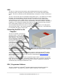
Connecting the SXL1 to the
Computer
The SXL1 is available in preconfigured
operational modes. These modes are
determined at point of manufacture or at OEM
depot distribution. Field configuration should
only be performed by installation specialists
to avoid configuration errors. Since the
device does not support over-the-air
configuration and must be connect using a
short range RF link, it is important the devices
are properly configured for use.
The SXL1 contains a short range RF
transceiver for setting the device for
operation. This transceiver communicates with a like transceiver in the SXL1 programming device.
The SXL1 programmer provides the interface for configuring the device using the SXL1_Programmer
setup tool available from Numerex.
®
The SXL1_Programmer software tool is designed to operate on a Microsoft Windows XP -based
computer. The Microsoft .NET framework is also required to run the configuration setup software.
®
This is a default Windows XP add-on, and may also be downloaded from www.microsoft.com
without charge.
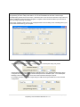
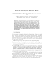
A USB Type A cable coming from the SXL1 programmer (right) is used to connect to the computer
being used to configure the device. Connect the computer to the SXL1 programmer using the USB
cable, and then run the SXL1_Programmer software tool. The SXL1_Programmer software will
automatically begin searching for available SXL1 units.
SXL1_Programmer Software
®
The SXL1_Programmer is a Windows executable software program designed to access and
configure the SXL1. The program can simply be copied to a directory on the computer.
5|Page
Proprietary and Confidential Revised 10-11-11
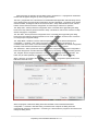
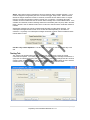
When launched, the program will auto-detect a SXL1 programmer. If a programmer is detected
the SXL tab will appear along the top of the program window
The SXL1_Programmer tool is structured as a standard Windows application with tabs along the top
of the display area that groups similar configuration controls and displays. The bottom of the display
remains constant; showing the ESN of the connected SXL1, sleep mode indicator/control, and two
buttons used to read back a device configuration or write/configure a device for operation.
The “Sleep SXL1” button queries the configuration of the connected device (populating the dialog
boxes of the tool) and then places the device to sleep. This button is used to force a devi ce to sleep
without changing the configuration.
The “Run SXL1” button queries the configuration of the connected device (populating the dialog
boxes of the tool) and then places the device into run mode. This button is used to force a device to
run using the pre-configured settings.
The “Sleep Mode” checkbox is used to select the operating mode of the device subsequent to
configuration. If checked, a unit is left in low-power sleep mode following programming. If
unchecked, the device is left in run-mode following programming. If a device is read for configuration,
the sleep mode checkbox will reflect the current state of the device being queried.
The “Read SXL1” button queries the device connected for configuration. The current configurations
held in the dialog boxes of all the tabs will be overwritten by the settings of the device being queried.
The “Program” button configures the device connected using the dialog boxes of all the tabs. The
button may be used repetitively on subsequent units to configure a set of devices identically.
When a device is connected to the computer and read, the SXL1_Programmer panel will show the
ESN in the lower left corner.
When the program is started the dialog boxes are initialized to the manufactured standard
configuration. If a device is read after being connected to the computer the dialog boxes are
populated with the device configuration. Connecting to a device after the program is launched will not
change the dialog boxes.
6|Page
Proprietary and Confidential Revised 10-11-11
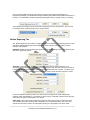
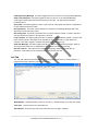
SXL Tab
The “SXL” tab only appears if the program detects that a SXL1 programmer is attached
to the computer. The SXL tab contains functions specific to the RF link between the
transceiver in the SXL1 and the SXL1 programmer.
When the program is first opened and it detects a SXL1 programmer, it will initiate a
scan for SXL1 devices within its RF range. The scan will last approximately 7.5 seconds.
If the ESN of the desired SXL1 does not show up in the discovered SXLs dialog box
there are 2 ways to try acquire a RF link with it. The first is to click the “Rescan” button.
This will start another 7.5 second scan for available devices. If the ESN is known it may
be typed into the lower dialog box and the “Add ESN(s)” button is clicked. This causes
the programmer to try and talk specifically to the specified device. Once the device is
found it will show up in the dialog box with the Status of connected listed next to it.
Click on the ESN that you would like to configure.
If the desired profile is currently being displayed by the setup tool and there are more
than one SXL1 that needs to be configured with this profile, click and drag down,
highlighting all of the devices to be configured. Once the devices are high lit, click the
“Program” button to configure them all at the same time.
7|Page
Proprietary and Confidential Revised 10-11-11
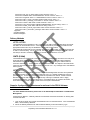
Standard Reporting Tab
The “Standard Reporting” tab is used to configure the device for routine position reporting. The SXL1
can be configured to report on a time delay between reports (Standard Interval) or at a specific time
of day (Time of Day). The pull down dialog box is used to select one or the other mode.
Or
Note that if Standard Interval is selected, the user may use the “Days, Hours, Minutes” controls to set
the amount of time between a standard location report. If “Time of Day” is selected, the “Days”
control is not available, the user is prompted to select the hour and minute of the day for reporting.
The device will wake once a day at this time to perform the standard report. Time of Day is provided
in UTC (GMT) format only. Displayed below the UTC setting is the correlating time of your current
time zone as set by your computer. If enabled for Time of Day, the user should specify the time at
Greenwich Mean Time for operation.
8|Page
Proprietary and Confidential Revised 10-11-11
Note: When programming SXL1 for Time of Day reporting:
Programming for Time of Day mode within 1 hour of the scheduled time will result in the first days
message being pushed out 24 hours. Also, if the device time is not current, the first time of day event may
take a complete 24 hours from time of program to complete. Users should thus allow up to 48 hours for
the unit to begin reporting on schedule.
Time of day reporting mode is set in UTC. Displayed below the UTC setting is the correlating time of your
current time zone as set by your computer.
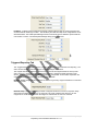
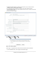
The Subsequent Message function is configured using the Subsequent dialog entry boxes:
Subsequent Messages are sent following the Standard report. The “Subsequent Messages” dialog
configures the count of messages to be sent subsequent to the standard report. The “Subsequent
Message Interval” sets the time in hours and minutes between subsequent reports.
For example, a device configured to report daily at 8 AM and hourly thereafter for 6 hours would be
configured as:
9|Page
Proprietary and Confidential Revised 10-11-11
Also, on the Standard Interval tab is the dialog to configure the Engineering Message. The
Engineering Message is a transmitted message containing data related to the health and operation of
the SXL1. It is advisable to send the Engineering Message routinely, typically monthly or bi-weekly.
The Engineering message interval may also be configured for time of day operation. This is useful,
for example, when requiring a daily count of engine runtime.
Motion Reporting Tab
The “Motion Reporting” tab is used to configure the device for detecting and reporting while in motion.
The Motion Reporting Mode pull down dialog box is used to select one of four modes of motion
detection and operation:
Disabled: Disabled mode configures the device to do nothing regarding motion. The Sensitivity and
Stop Time dialogs are ignored.
Start Only: Start Only mode configures the device to detect start of motion and report. The
Sensitivity sets the device for low, medium and high sensitivity. Stop Time sets the amount of time in
minutes that the unit does not detect motion, before the device drops out of motion. The Start Time
sets the amount of time in minutes that the unit detects motion, before the device reports in motion.
As with the Standard reporting function, the device may be configured to report subsequently
following motion start detection. For example, a device may be configured to detect motion start and
report every 30 minutes subsequently for 4 reports.
Start / Stop: Start / Stop mode configures the device to detect start or stop of motion and report.
The Sensitivity and Start and Stop Time configurations are as described earlier. The device only
reports start and stop of motion. No subsequent reporting is configurable in this motion mode.
10 | P a g e
Proprietary and Confidential Revised 10-11-11
In Motion: In Motion mode configures the device to detect start and stop of motion and report at a
set interval while remaining in motion. The Sensitivity and Start and Stop Time configurations are as
described earlier. The Subsequent Message Interval controls set the time between reports while the
unit remains in motion. The Subsequent Message dialog (count) is ignored.
Triggered Reporting Tab
The “Triggered Reporting” tab is used to configure the device for alarm detection and reporting. The
SXL1 has two integral alarms that may be configured, magnet reed switch.
The magnet reed switch detects the presence or removal of the magnet inserted in the top of the
SXL1 enclosure. Removal of the magnet while the device is asleep will initiate operation of the
device. Action on reinsertion/removal of the magnet is configurable. Three modes of operation are
supported for magnet function while the device is in run mode.
Disable: Disable magnet mode configures the device to ignore any magnet reinsertions or removals
while in run mode.
Resume Sleep: Resume Sleep magnet mode configures the device to return to low-power sleep
state when the magnet is inserted for 15 seconds. This mode configures the device to use the
magnet as an on/off switch. Off when the magnet is inserted and on when it is removed.
11 | P a g e
Proprietary and Confidential Revised 10-11-11
Alarm: Alarm magnet mode configures the device to initiate an alarm message operation. In this
mode the magnet is recognized by the SXL1 but does not trigger “sleep mode”. When the device
detects the magnet inserted for at least 15 seconds, the device will arm itself for alarm on magnet
removal. The alarm is triggered on magnet removal only, not insertion. The dialog “GPS FIX?”
checkbox is used to instruct the SXL1 to send an alarm message with or without GPS location. If the
checkbox is unchecked, the alarm message will be sent immedi ately with null (zero) data in the GPS
fields. If the SXL1 has not detected motion since it’s GPS fix it will send those coordinates instead of
null data.
Subsequent messages may also be configured that will follow the initial alarm message. The
subsequent messages will also contain or not contain GPS data depending on the GPS FIX
checkbox. If a quantity of 31 subsequent messages is entered, the alarm will be considered infinite
until the alarm is reset.
Cut Wire / Dry Contact Operation: The SXL1 does not support the Cut Wire functionality of the
SX1.
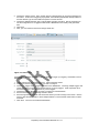
Testing Tab
The “Testing” tab supports field evaluation and testing of devices using a variety of manual
commands and queries. The Testing tab provides the interfaces to force message transmissions or
query GPS or evaluate engineering data. In order to receive the on-air messages the SXL1 must be
outside or taken outside immediately after clicking the button. To query the GPS, the SXL1 must be
outside when the query is initiated. The tab dialog window appears as shown below:
12 | P a g e
Proprietary and Confidential Revised 10-11-11
Send Engineering Message: This button triggers the SXL1 to send an on-air Engineering Message.
Send Custom Payload: This button triggers the SXL1 to send an on-air Raw Data Message
containing the first 8 bytes entered into the text box to the right. The data must be entered in
hexadecimal form.
Query GPS: This button triggers the SXL1 to get a GPS fix and populate the Latitude, Longitude and
Fix time textboxes above the button.
Get Engineering: This button queries the SXL1 to retrieve the Engineering Message data to the
large textbox to the right of the button.
Get Testing Data: This button queries the SXL1 to perform a device self-test. The SXL1 will return
self -test results to the textbox to the right after 5 seconds.
Loop Test Data: This button queries the SXL1 to perform a repetitive device self-test. The SXL1 will
return self-test results to the textbox to the right after a couple of seconds (~7) and repeat until
canceled. Test data is logged to a test file C:\Program Files\SXL1\SXL1.log.
Send GPS Message: This button triggers the SXL1 to send an on-air location message. Allow for
up to 30 minutes for the SXL1 to determine the GPS location and send the message.
Get Last Location: This button returns the latitude, longitude, and time of the last GPS fix
performed. Note that this is not necessarily the current location and time.
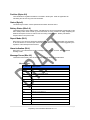
Info Tab
The “Info” tab collects all communications to and from connected devices in a scrolling textbox. It
supports testing and evaluation of devices connected.
Reset Battery: Resets the battery counter on the SXL1, a window will pop up to verify the change.
Clear Text: Clears the text in the information box.
Show Events: Shows pending and recent events that are in the S XL1 scheduler.
13 | P a g e
Proprietary and Confidential Revised 10-11-11
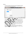
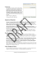
Profiles Tab
The “Profiles” tab is used to save and retrieve device
configuration files called Profiles. A configuration may
be saved to a new file by entering a filename in the
topmost textbox and selecting “Save as New Profile”.
Existing profiles appear in the bottom textbox and may
be loaded into the tab configuration boxes by selecting
“Load Profile” or deleted by selecting “Delete”. The
“Save as Selected” allows a previously saved profile to
be edited.
Profiles are kept in a database file
C:\Program Files\SXL1\SXL1.db
Operational Standards
The SXL1 is a fully self-contained, small profile asset tracking device suitable for extended exposure
to outdoor and industrial environments. It is 3.25 inches wide, 3.25 inches long and 2.0 inch in
height. The device enclosure is molded polycarbonate. The enclosure is ultraviolet resistant and
designed to survive physical and temperature shock The battery is field replaceable. The SXL1 only
need be snapped out of it’s mounting sled to replace the battery.
The enclosure is divided into two sections, one holding the electronics assembly and the other
holding the battery assembly. The two sections are environmentally sealed from each other and from
the outside of the device. The electronics assembly passes all electrical signals through the barrier
between the two sections.
The unit contains a recessed well in the lid used to insert a magnet. This magnet aligns with the
embedded reed switch and is used to wake the device or trigger an alarm message. The magnet
must be removed for the device to function.
Mounting Provisions
The SXL1 mounting plate is smooth surfaced on the bottom to provide for adhesives mounting.
Additionally four countersunk screw holes are provided for screw mounting. The SXL1 snaps into the
mounting plate and can be secured to the mounting plate with a zip-tie or a #10 x !” self tapping
screw.
Select a mounting location for the device that provides the clearest unobstructed view of the sky as
possible on the highest, flattest, hardest surface possible. A location that allows mounting of the unit
in a horizontal orientation provides the best view of the sky and thus greater thru put. Contact
Numerex for vertical mount considerations. A location that protects the unit from potential damage
due to tie-down straps, forklift, shifting cargo, container stacking, etc. is recommended. Note that
these hazards can also hinder message thru put.
When mounting, ensure that the unit has been properly programmed, has been placed in RUN mode
and the magnet has been removed. Several mounting techniques are available and may vary due to
application of use: VHB tape, screws, etc.
Power Standards Outline
The SXL1 operates using series pairs of 3.0V lithium metal batteries. The device uses the 6.0V DC
voltage for all battery powered operation. The battery assembly is intrinsically safe.
14 | P a g e
Proprietary and Confidential Revised 10-11-11
Each of the 3V batteries has an operational range of 2.1 to 3.0V, with end of life near 1.85V (3.7V for
each series pair).
New Battery Installation
For installation of a battery on a new SXL1, remove battery from packaging. Ensure that the gray
neoprene gasket is in place around the oval connection port to the electronic assembly section of the
SXL1. Verify that you have two 6/32 T10 Torx security screws to affix the battery to the unit. Slide
the rear of the battery into the notches on the SXL1, rotate the front of the battery down gently into
place being careful not to damage the connection pins. Place one 6/32 screw into each hole on top
of the battery and tighten to approximately 10 inch pounds
Battery Replacement
In order to replace the battery of the SXL1 remove the zip-tie or screw securing the SXL1 to the
mounting plate. While lightly pulling up on the SXL1, use a screwdriver to gently pry the locking tabs
away from the body of the SXL1. Once the SXL1 is removed from the mounting plate remove the two
screws holding the battery to the SXL1 using a T10 Torx security screwdriver. Rotate the front
portion of the battery up and remove the battery. Inspect the gaskets and connection ports for debris
and clean if necessary. Remove the replacement battery from its packaging, ensuring that the gray
neoprene gasket is in place around the oval connection port. Verify that you have two 6/32 T10 Torx
security screws to affix the battery to the SXL1. Slide the rear of the battery into the notches in the
SXL1 and rotate the front of the battery gently down into place being careful not to damage the
connection pins. Replace the battery screws in each hole on the top of the battery and tighten to
approximately 10 inch pounds. After replacing the battery use the SXL1 setup tool to reset the
battery count; this will ensure the engineering messages reflect an accurate battery power remaining.
Battery Counter Reset
See “Info Tab” section (page 14) for directions.
Battery Voltage
The SXL1 operates over the voltage variations of the battery under load.
6Vbat = 3.8V to 6.0V at voltage of batteries
Pulse current = 500 mA at 6.0 V over temperature
The SXL1 incorporates a hardware watchdog and brown out detector that will reset the electronics of
the device if the voltage drops below the minimum operable voltage. The electronics assemblies will
resume operation following reset with no degraded performance. The SXL1 will experience no loss of
non-volatile parameters.
Battery Low Threshold
The SXL1 triggers a Low Battery State when the battery capacity reaches 12.5% useful life remaining
(calculated by the device in operation). The device also contains low voltage and brown out protection
that will restart the unit upon a power interruption event.
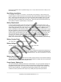
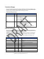
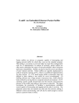
Power Supply / Battery Life
The SXL1 is powered by field-replaceable lithium metal batteries. The typical operational battery life
(and expected location report count) is a function of use as shown in the graph below. Extended
temperature of use (outside –20 to +60 C) or obscured view of sky resulting in more cold-start GPS
fixes can shorten battery life. The graphs below depict typical usage curves. Environmental
conditions and device placement with respect to sky visibility will impact device performance.
15 | P a g e
Proprietary and Confidential Revised 10-11-11
SXL1 Serial Message Protocol
The SXL1 uses the on board RF transceiver and the programmer for both configuration and support
of wireless sensors. The SXL1 programmer can accept serial commands from a sensor or it can be
connected directly to a open/closed or analog sensor. This user’s manual contains the messaging for
serial wireless sensors only. When the programmer is connected to an open/closed or analog sensor
it uses the following protocol to send the appropriate message to the SXL1 for transmission.
Serial Protocol
The SXL1 may be configured using USB commands via the configuration connector. The SXL1
accepts USB serial logic levels between 0 to 5.0V DC. The interfacing connectivity provides voltage
and inrush protection for the interface.
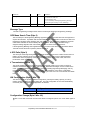
The serial protocol conforms to the following general format. Each message starts with a preamble
byte followed by a length byte followed by a serial command designator, payload and concludes with
a two-byte CRC.
Preamble
(1 byte)
Length
(1 byte)
Cmd
(1byte)
Data
(Variable)
CRC
(2bytes)
5 to 54 bytes
Serial Set Format (Commands & Answers)
The different fields are defined as:
Serial Packet Fields
Position
Preamble
Length
Cmd
Data
CRC low
CRC high
Bytes
Fixed pattern 0xAA
Total number of bytes in the serial et including the preamble
Command type (See section 3.2 below). Responses to commands
carry the same command type as the command that initiated the
answer
Data associated with the command or answer
Least significant byte of the 16-bit CRC
Most significant byte of the 16-bit CRC
16 | P a g e
Proprietary and Confidential Revised 10-11-11
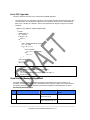
Serial CRC Algorithm
The CRC checksum uses the CCITT-16 Reversed (0x8408) algorithm:
The Security Field is a 16-bit CRC of all of the previous fields including the preamble, length, and
command bytes. The remainder is initialized to all 1's (0xFFFF) and the CRC is inverted before
being sent. Following is a sample C routine that implements the algorithm using the "reversed"
technique:
WORD crc16_lsb(BYTE *pData, WORD length)
{
BYTE i;
WORD data, crc;
crc = 0xFFFF;
if (length == 0)
return 0;
do
{
data = (WORD)0x00FF & *pData++;
crc = crc ^ data;
for (i = 8; i > 0; i--)
{
if (crc & 0x0001)
crc = (crc >> 1) ^ 0x8408;
else
crc >>= 1;
}
}
while (--length);
crc = ~crc;
return (crc);
}
As an example, for a type (0x01) “Get ID” message made up of the following bytes:
AA 05 01
The following 2 byte CRC would be calculated:
D5 50
The complete message sent by the host to the SXL1 is:
AA 05 01 50 D5
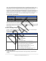
Serial Sensor Messages Supported
The serial format is utilized for all serial messaging as described in the sections following. All
messages are acknowledged with the command field of the response equal to the command field of
the initiating message. Invalid formatted commands are negatively acknowledged by the SXL1.
Serial Sensor Message Types
Cmd
Description / Usage / Comment
Command Data Bytes
Acknowledge Data
Bytes
0x04
Remote Data Command
See “Remote Data
Command” pg 20
None
0x05
Remote Sensor Alarm Command
See “Remote Sensor
Alarm Command” pg. 20
1 byte = alarm accepted
17 | P a g e
Proprietary and Confidential Revised 10-11-11
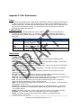
Remote Data Command (message type 0x04)
The SXL1 supports remote sensors or other devices that force a satellite transmitted message using
this command. The external interface may relay up to 8 bytes of data for transmission by the SXL1
over the system. Format of the user data is undefined.
The SXL1 acknowledges receipt of the Remote Data Command immediately, then sends the data to
the satellite system using message type 0xCF (Remote Message pg 24).
The Remote Data Command is in the following format:
Bit Mask for Remote Data Command
Bit
Parameter
63:0
User Defined
Description
Configure (C) or
Query (Q)
C
Remote Sensor Alarm Command (message type 0x05)
The SXL1 does support remote sensors or other devices that force a satellite transmitted message
and may optionally enable subsequent reporting using this command. Upon receipt of this command,
the device enters the data parameters into the event table for reporting. If the event table is full, the
device responds to the device with a negative acknowledge message.
If the event table can accept another entry, the SXL1 positively acknowledges receipt of the
command immediately, and then initiates the alarm message function. Alarm messages are standard
on-air Location Messages (pg. 21) with the alarm bits set accordingly. The Remote Sensor Alarm
Command is in the following format:
Bit Mask for Remote Sensor Alarm Command
Bytes
0-1
Parameter
Sensor Interval
(minutes) + count
3
Message Cause
Description
Bits 9:0 = alarm-triggered interval
Bits 14:10 = alarm count
Bit 15: 0= report null (0’s) GPS data, 1=insert GPS
Bits 3:0 = message cause
Sending sensor interval and a count value of zero disables alarm messaging. This can be used to
suspend (terminate) any ongoing alarm messaging.
Sending sensor interval and a count value ranging from 1 to 30 will initiate an alarm immediately and
subsequent messages totaling the count value. Count value of 1 initiates a single alarm message.
Count value of 31 initiates an infinite number of subsequent alarm messages.
The device will send alarm notifications containing or omitting GPS data per the setting of bit 15 of
bytes 0&1.
Alarm triggered interval sets the minutes between first and subsequent alarm messages initiated by
the SXL1. This term “set to zero” instructs the S XL1 to send the alarm message only once.
SXL1 On-Air Message Protocol
The SXL1 transmits data via the embedded satellite transmitter. The SXL1 initiates a satellite
transmission following location determination or to relay engineering data that is useful for evaluating
the health of the device over time. This section describes the on-air messages emanating from the
18 | P a g e
Proprietary and Confidential Revised 10-11-11
SXL1. Each message below describes the payload region of the satellite burst message. The
network protocol is removed from this description for clarity. Network operators utilizing the resulting
internet packets must refer to Globalstar documentation regarding Simplex Data Service use.
All on-air SXL1 messages follow the payload format depicted below. Because the satellite packet is
restricted to 9 bytes total, the message fields are used sparingly. The first byte of every on-air
message contains the message type identifier. The message type identifier is the least significant 2
bits of the first byte of data. The SXL1 may emit the following 4 types of on-air messages:
On-Air Message Type Definition
Message Type (5
LSbits of first byte)
11001011 (0xCB)
11001111 (0xCF)
11010011 (0xD3)
11010111 (0xD7)
Message Payload Content
Location Message (contains GPS location data)
Remote Message
Termination Message
Engineering Message
The least two significant bits are set to 0x11 with the upper six bits constrained to a range of 0x32 to
0x35 to avoid conflict with other satellite transmitters that use a similar on-air protocol.
The subsequent 8 bytes are encoded as described below depending on the message type. For data
fields that span multiple bytes, the parameters are sent most significant byte first, most significant bit
first in each byte.
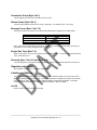
Location Message Format
The SXL1 transmits location data using the Location Messaging format. The Location Message is
denoted as message type 0xCB and will follow the format:
Location Message Format
Byte
Bits Description
0xCB = Message Type
8
Bit 7:0 = 0xCB = SXL1 Location message type:
Latitude / Longitude
48
Status
16
Byte 1 = Latitude MSByte
Byte 2 = Latitude
Byte 3 = Latitude LSByte
Byte 4 = Longitude MSByte
Byte 5 = Longitude
Byte 6 = Longitude LSByte
(see section 2.3.1 and 2.3.2 for encoding method)
Bit 2:0 = battery status
Bit 3 = 0 = standard interval report, 1= subsequent interval report
Bit 4 = alarm (0=no alarm, 1=alarm w/ cause defined)
Bit 8:5 = message cause (valid when Bit 4 = 1)
Bit 9 = 1= engine run-time data is in message cause field
Bit 10 = configuration change (toggles)
Bits 13:11 = message count (modulo 7 count)
Bit 14 = motion state, 0 = unit is stationary, 1 = unit in motion
Bit 15 = 0=3D GPS Fix found, 1=2D GPS Fix found
Message Type (Byte 1)
The SXL1 standard location message shows 0xCB in the first byte denoting a standard location
message.
19 | P a g e
Proprietary and Confidential Revised 10-11-11
Position (Bytes 2-8)
The Latitude and Longitude information is encoded in these bytes. Refer to Appendix B for
calculating the Lat and Long from this information.
Status (Byte 9)
The Status byte contains various operational information about the SXL1.
Battery Status (Bits 2:0)
These bits hold the current battery status, calculated by the device and reflected proportionally in this
field. Battery status starts at seven (7) and counts down in 12.5% resolution of usage. Replacing the
batteries will require the user to reset to this count using command 0x31. Battery calculations
suspend while in line power mode.
Report Mode (Bit 3)
When set to 0, the device is reporting a standard location message generated either from expiration
of an interval timer or an alarm input. When set to 1, the device is reporting location triggered by the
expiration of the subsequent interval timer.
Alarm Indication (Bit 4)
When set to 1, this denotes the location message is generated by an alarm. Bits 8:5 hold the
message cause.
Message Cause (Bits 8:5)
These bits hold the binary value of the message cause as shown in the table below:
Message Cause
Bit Pattern
Description
0000
Standard Location Message
0001
Reed Switch
0010
Cut-wire (USB Cable) alarm
0011
Motion alarm
0100
Line Powered
0101
undefined
0110
undefined
0111
undefined
1000
Digital Custom Sensor 1
1001
Digital Custom Sensor 2
1010
Digital Custom Sensor 3
1011
Digital Custom Sensor 4
1100
Digital Custom Sensor 5
1101
Digital Custom Sensor 6
20 | P a g e
Proprietary and Confidential Revised 10-11-11
1110
Analog Custom Sensor 1
1111
Digital Custom Sensor 7
Note: Remote message cause 0 through 7 translate to message cause 8 through 15 (bit 4 = 1 =
remote alarm initiated).
The message cause field alternatively can hold engine run time data as described below in the bit 9
description.
Engine Run Time (Bit 9)
This bit is zero unless the device is configured for engine run time (Cut Wire Configuration in Run
State byte of the configuration message). If configured for engine run time and the SXL1 is reporting
a standard, interval driven location message, this bit 9 is set and the message cause fields (bits 8:5)
are redefined to hold 16-hour resolution count of engine run time. This means that the true message
cause is 0000 and the field normally holding the message cause now contains engine run time count
in 16 hour resolution.
This is only true for standard interval driven location messages. Event driven location messages
such as alarms or motion will not contain engine run time data and this bit 9 will be cleared.
Configuration Change (Bit 10)
Toggles each time the device is reconfigured.
Message Count (Bits 13:11)
Modulo 7 count that increments each time the device sends a message (counts 0 to 7 then starts
again at 0).
Motion State (Bit 14)
Holds current state of motion for the device. 0 is stationary while 1 is in motion.
GPS 2D/3D (Bit 15)
Validates the GPS fix as 2D or 3D. 0 is a 3D fix while 1 is a 2D fix.
Remote Message
The SXL1 supports remote generated messages containing 8 bytes of user data with a message type
0xCF. This is provided for remote sensors and other devices that serially issue a Remote Data
command via the USB connection. This message is created upon receipt of serial command type
0x04, Remote Data Command (pg. 20)
Remote Message Format
Byte
Bits Description
0xCF = Message Type
8
Bit 7:0 = 0xCF = SXL1 Remote message type:
Sensor Info
64
Sensor Defined information
21 | P a g e
Proprietary and Confidential Revised 10-11-11
Termination Message
The SXL1 automatically stops functioning, issuing a termination message upon completion of the
termination count as configured by the configuration serial command. The Termination Message is
the same format as a location message except the message type is 0xD3.
Termination Message Format
Byte
Bits Description
0xD3 = Message Type
8
Bit 7:0 = 0xD3 = SXL1 Termination message type:
Latitude/Longitude
48
Status
16
Byte 1 = Latitude MSByte
Byte 2 = Latitude
Byte 3 = Latitude LSByte
Byte 4 = Longitude MSByte
Byte 5 = Longitude
Byte 6 = Longitude LSByte
(see section 2.3.1 and 2.3.2 for encoding method)
Bit 3:0 = undefined
Bit 4 = alarm (0=no alarm, 1=alarm w/ cause defined)
Bit 7:5 = message cause (valid when Bit 4 = 1)
Bit 8 = configuration change (toggles)
Bits 13:9 = message count (modulo 7 count)
Bit 14 = motion state, 0 = unit is stationary, 1 = unit in motion
Bit 15 = 0=3D GPS Fix found, 1=2D GPS Fix found
Engineering Message
The SXL1 automatically issues an Engineering Message following expiration of the Engineering
Interval as set in the serial Configuration message. This data may also be extracted over the serial
configuration port using the Query Engineering Data command.
Additionally, the Engineering Message is transmitted on first run of the device or if it encounters a
watchdog reset. Associated bits in the message indicate the origination cause for the message.
The Engineering Message contains parameters that relay the operability of the device in use.
Engineering Message Format
Variable
Byte
Bits
Description
0xD7 = Message Type
0
8
Bit 7:0 = 0xD7 = SXL1 Engineering message type:
GPS Mean Search Time
1
8
# GPS Fails
2
8
#Transmissions
HW configuration
Configuration Change
3-4
5
5
16
3
3
Termination Reset
Motion Status
Battery Status
5
5
6
1
1
(2:0)
Unsigned binary count in seconds for mean GPS search
to acquire
Unsigned binary count in seconds of failed GPS
attempts since last engineering message
# of transmissions since device began service
defines hardware and battery configuration
Modulo 7 count incrementing each time device is
configured
Toggles each time the termination count is reset
0=stationary, 1=motion
Battery status. Percent battery life remaining in 12.5%
increments.
Magnet Status
6
3
0=magnet absent, 1=magnet present
22 | P a g e
Proprietary and Confidential Revised 10-11-11
undefined
Message Cause
6
6
(5:4)
(7:6)
Engine Run Time
7-8
16
undefined
00 = Engineering interval expired
01 = First run of device
10 = Watchdog reset
11 = Low battery warning (Engineering message
generated upon reaching 12.5% remaining)
Hours of cut wire detection accumulated.
Message Type
The SXL1 Engineering message shows 0xD7 in the first byte denoting an Engineering message.
GPS Mean Search Time (Byte 2)
The second byte of the Engineering Message payload contains information about the average time to
acquire GPS location. A problem with the GPS hardware may be detected in mean time to search as
indicated by this data. Asset managers may use this data to find problematic installations as well as
make better estimates for terminal battery life of the product. Mean time is calculated using a
weighted average algorithm with a time base of at least 16 most recent transmissions.
If the Engineering Message was originated due to a First Run of the device, the GPS Mean Search
Time will hold the seconds required to perform the first fix.
# GPS Fails (Byte 3)
The third byte of the Engineering Message payload contains a count of the number of times the unit
failed to acquire a GPS fix since the last Engineering message. This count is cleared following
transmission of the Engineering message. This field will report a max value of 255, even if the
transmission count exceeds 255.
# Transmissions (Bytes 4:5)
The fourth and fifth byte of the Engineering Message payload contains a count of the number of
satellite transmissions since the device was enabled. Redundant messages are not included in the
count. All valid transmissions are included in the count including Engineering Messaging, and any
forced messages. This count is cleared by resetting the termination count via the configuration
connector. The fourth byte holds the most significant byte of the word. The count will roll-over 65535
to 0.
HW Configuration (Byte 6, bits 7:5)
The device reports the specific hardware configuration, primarily the battery capacity, for use by
remote monitors to determine end of battery life. The HW Configuration is set in the Reset Battery
Command (0x31). The following configurations are defined:
Bit pattern
Configuration
000
Primary Battery 3200 mAh
Configuration Change (Byte 6 bits 4:2)
Modulo 7 count that increments each time the device is configured (counts 0 to 7 then starts again at
0).
23 | P a g e
Proprietary and Confidential Revised 10-11-11
Termination Reset (Byte 6 bit 1)
This bit toggles each time the Termination Count is reset.
Motion Status (Byte 6 bit 0)
This bit shows whether the device is moving or stationary. 0 is stationary and 1 is mo ving.
Message Cause (Byte 7 bits 7:6)
These two bits show the reason for the Engineering Message as explained in the table below:
Bit Pattern
00
01
10
11
Explanation
Engineering interval expired
First run of device
Watchdog reset
Low battery warning
Note: The SXL1 will automatically generate an engineering message when the battery remaining is
calculated at 12.5% setting message cause to type 3 (11).
Engine Run Time (Byte 7:8)
Bytes 7 and 8 are a 16 bit count of minutes of accumulated run time. Once the value reaches 65,535
hours it will rollover to 0.
Reserved (Byte 7 bits 5:0 and Bytes 8:9)
The remaining bits in the Engineering Message are currently undefined and reserved for future use.
Regulatory Approvals
See Appendix A for the SXL1 regulatory certifications
Labeling and Marking
The SXL1 displays all required regulatory and certification markings visible on the top, which will be
labeled or indelibly printed on the plastic. The ESN of the device is labeled or printed in both decimal
numerals and bar code. All markings are weather resistant and permanently affixed. Customers
must leave these required marks visible or duplicate the data in their own labels.
Unit ID
Each unit has a unique Transmitter ID (ESN).
24 | P a g e
Proprietary and Confidential Revised 10-11-11
Appendix
Appendix A: Regulatory Notices
The SXL1 contains a GPS radio receiver and simplex radio transmitter as well as a digital-computing host
interface board. The FCC requires the following notification for the device in compliance with 47CFR
15.105 for this Class B digital device. Full product test reports are available from Numerex upon request.
NOTE: This equipment has been tested and found to comply with the limits for a Class B digital
device, pursuant to Part 15 of the FCC Rules. These limits are designed to provide reasonable
protection against harmful interference when the equipment is operated in a residential
environment. This equipment generates, uses, and can radiate radio frequency energy and, if not
installed and used in accordance with the instruction manual, may cause harmful interference to
radio communications. However, there is no guarantee that interference will not occur in a particular
installation. If this equipment does cause harmful interference to radio or television reception, which
can be determined by turning the equipment off and on, the user is encouraged to try to correct the
interference by one or more of the following measures:
?
?
?
?
Reorient or relocate the receiving antenna.
Increase the separation between the equipment and receiver.
Connect the equipment into an outlet on a circuit different from that to
which the receiver is connected.
Consult the dealer or an experienced radio/TV technician for help.
WARNING: Changes or modifications not expressly approved by Numerex may render the device
non-compliant to FCC and other regulatory body standards for operation and may void the user’s
authority to operate the equipment.
Accessory items that can be readily obtained from multiple retail outlets are not considered to be
special accessories and are not to be marketed with the equipment. Only those accessory items
provided by Numerex have been tested to ensure operation consistent with the regulatory standards
that the device is required to perform.
This device complies with Part 15 of the FCC Rules. Operation is subject to the following two
conditions: (1) This device may not cause harmful interference, and (2) this device must accept any
interference received, including interference that may cause undesired operation.
25 | P a g e
Proprietary and Confidential Revised 10-11-11
NOTICE: This equipment complies with the FCC RF Exposure Limits. A minimum of 20 centimeters
(8 inches) separation between the device and the user and all other persons should be maintained.
FCC and IC certified transmitter
FCC ID: TWV-SXL1
IC: 6322A-SXL1
Contains: FCC ID: TWV-SXL1FLEX
Contains: IC: 6322A-SXL1FLEX
The SXL1 is certified to the following safety standards:
UL60950-1/CSA C22.2 No. 60950-1, Second Edition: Safety of Information Technology Equipment,
Dated March 27, 2007.
th
UL 913, 6 edition: Intrinsically Safe Apparatus and Associated Apparatus for use in Class I, II, and III,
Division 1, Hazardous (Classified) Locations, revised August 9, 2004.
CSA C22.2 No. 157-92 R2006: Intrinsically Safe and Non-Incendive Equipment for Use in Hazardous
ocations.
The SXL1’s MET listing file number is:
Appendix B: Calculating Lat / Long
Calculating Lat / Long from SXL1 Messages
The SXL1 uses 3 byte fields to encode Latitude and Longitude information. The data is encoded to
represent a specific location with sufficient accuracy
as to
notConfidential
degrade location
data
from the GPS
Proprietary
and
Revised
10-11-11
system.
26 | P a g e
!
!
!
!
The SXL1 encodes 180 degrees of LATITUDE as a 24-bit (3-byte) signed integer.
The SXL1 encodes 360 degrees of LONGITUDE as a 24-bit (3-byte) signed integer.
The encoded LATITUDE data is the first three bytes of the location data payload
The encoded LONGITUDE data is the next three bytes of the location data payload.
Lat2
!
!
!
!
!
!
Lat1
Lat0
Long2
Long1
Long0
Lat2 – Latitude MSB
Lat1 – Latitude
Lat0 – Latitude LSB
Long2 – Longitude MSB
Long1 – Longitude
Long0 – Longitude LSB
CALCULATING LATITUDE FROM ENCODED SXL1 MESSAGES
Latitude may be calculated by converting the 3 encoded latitude bytes represented in hexadecimal to
a decimal number and multiplying this decimal integer by the DEGREES_PER_COUNT_LAT
23
conversion factor 90.0 / 2 .
Since the latitude is signed and can range from –90 to 90 degrees, if the above result is greater than
or equal to 90 degrees, 180 must be subtracted from the result.
Negative Latitude corresponds to Latitude in the SOUTHern Hemisphere.
Positive Latitude corresponds to Latitude in the NORTHern Hemisphere.
CALCULATING LONGITUDE FROM ENCODED SXL1 MESSAGES
The longitude may be calculated by converting the 3 encoded longitude bytes represented in
hexadecimal to a decimal number. This decimal integer is multiplied by the
23
DEGREES_PER_COUNT_LONG conversion factor 180.0 / 2 .
If the above result is greater than or equal to 180 degrees, 360 must be subtracted from the result
since the longitude is signed and can range from –180 to 180 degrees.
Negative Longitude corresponds to Longitude in the WESTern Hemisphere.
Positive Longitude corresponds to Longitude in the EASTern Hemisphere.
27 | P a g e
Proprietary and Confidential Revised 10-11-11
Appendix C: SXL1 Data Interface
Scope
This document describes the SXL1 Data Interface (Datastreams ) transport methods and data formats
available for machine-t o-machine communications from a device to a Value Added Reseller (VAR) or
customer’s back office. All methods and formats described in this document can be configured in the
FELIX Software Administration website. It is assumed the reader is familiar with the terms and
technology described in this document.
Transport Layers
The Datastream functionality implements common Internet transport layers to facilitate ease of
integration with the VAR back office. The following protocols can be utilized for data transport:
HTTP/HTTPS, SMTP (E-Mail), and SFTP. For a description of these protocols please refer to the
table below.
Acronym
HTTP/HTTPS
Description
Hypertext Transport
Protocol (Secure) 1.1
SMTP (E-mail / Simple Mail Transport
SMS)
Protocol (Electronic Mail)
SFTP
Secure File Transport
Protocol
Reference
http://tools.ietf.org/html/rfc2068
http://www.ietf.org/rfc/rfc0821.txt
http://www.openssh.org/txt/draft-ietfsecsh-filexfer-02.txt
Data Formats
Tracker XML Description
trackermessages: The root element of the Tracker XML which contains the individual tracker
messages.
trackermessage: The element for each tracker message that generated the trigger. Normally only
one tracker message will be sent during each transmission.
asset: The element containing the FELIX fields of the Asset. Values for the elements are attained at
the time the message is forwarded.
esn: The Electronic Serial Number of the Tracking Device. The format of this field will be different,
depending on the type of Tracking Device.
name: The FELIX Asset Name. This value is a free text field that may contain spaces and non
alphanumeric characters.
user_data: The FELIX “Custom Fields” as configured by Administrative users and as assigned to
the Asset. The data for the custom field is free text, spaces are allowed.
field name: The field name will represent the Organization defined custom field name as assigned to the
asset. The “data” field will represent the value of the field defined for the Asset.
cause : This element and its children refer to the FELIX datastream trigger that is configured to
forward the tracker message when certain conditions are met.
trigger: The FELIX datastream trigger that was configured to send this message. This will match the
list of triggers found in FELIX.
condition: The condition that was matched that triggered this forwarded message. The options for
this condition are specific to the tracking device sending the message unless the trigger is set for
any message received.
position: The position information, and calculated address information of the position in formation.
coordinate: The Tracker XML outputs the coordinates in type “dd”, decimal degrees.
latitude: The latitude reported in the forwarded tracker message, and determined by the
hexadecimal field in the payload.
28 | P a g e
Proprietary and Confidential Revised 10-11-11
longitude: The longitude reported in the forwarded tracker message, and determined by the
hexadecimal field in the raw payload.
address: The address calculated by the latitude and longitude. The address is an approximation
made on available geographic data, it is not intended to be exact.
street_address: The approximation of the number and street information by the latitude and
longitude. The address number may or may not be present, depending on the street type. The
street may be a road, avenue, highway or other designated type and is an approximation of the
nearest street to the location.
city: The city the address resides in.
state: The state the address resides in (if applicable).
zip: The US Postal zip code the address resides in(if applicable).
county: The county the address resides in (if applicable).
motion: The value reported by the tracking device for the motion status at the time of the report.
This may be a different result than the motion sensor trigger that may be configured as they are
derived by different methods.
payload: The following attributes will represent the parsed payload of the message data and the
related value. The specific field names will depend on the message type and specific configuration
of the tracking device.
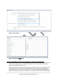
Tracker XML Example
<?xml version="1.0" encoding="utf-8" ?>
<trackermessages version="1.0">
<trackermessage type="SXL1_location" id="22844855" positional="true" unixtime="1231360613">
<asset>
<esn>0-301896</esn>
<name>TEST UNIT</name>
<user_data>
<field name="customfield1" data="text" />
</user_data>
</asset>
<cause>
<trigger>All Devices: Any Message: Any Data is received</trigger>
<condition>Message Received</condition>
</cause>
<position>
<coordinate type="dd">
<latitude>45.679092407227</latitude>
<longitude>-111.03650093079</longitude>
</coordinate>
<address>
<street_address>50 E Main St</street_address>
<city>Bozeman</city>
<state>MT</state>
<zip>59715</zip>
<county>Gallatin</county>
</address>
</position>
<motion>false</motion>
<payload>
<field name="SXL1_alarm_status" data="false" format="boolean" units="" />
<field name="battery" data="100" format="numeric" units="" />
<field name="SXL1_config_change" data="false" format="boolean" units="" />
<field name="SXL1_engine_runtime" data="" format="numeric" units="" />
29 | P a g e
Proprietary and Confidential Revised 10-11-11
<field name="2d_gps_fix" data="false" format="boolean" units="" />
<field name="latitude" data="45.679092407227" format="numeric" units="" />
<field name="longitude" data="-111.03650093079" format="numeric" units="" />
<field name="SXL1_alarm_type" data="0000" format="string" units="" />
<field name="SXL1_message_count" data="7" format="numeric" units="" />
<field name="motion" data="false" format="boolean" units="" />
<field name="raw_payload" data="CB40F740B10A6C3807" format="string" units="" />
<field name="status_code" data="CB" format="string" units="" />
<field name="SXL1_interval_report" data="false" format="boolean" units="" />
<field name="SXL1_termination_message" data="false" format="boolean" units="" />
</payload>
</trackermessage>
</trackermessages>
Delivery Methods
HTTP / HTTPS
The Datastream will encapsulate an SXL1 message in the XML format described above and POST
the data to an HTTP/HTTPS server. A list of IP addresses will be provided to the VAR such that
appropriate firewall rules may be established. HTTP Basic Authentication
(http://www.ietf.org/rfc/rfc2617.txt) is available upon request. The Content-Type will be text/xml with
no URL or other encoding. For an HTTP Post, the receipt of an acknowledgement (HTML Code in
the 200’s) is all that is necessary for FELIX to consider the transmission a success.
SMTP (E-Mail)
The Datastream will encapsulate a message in a Tracker Message XML document in the body of an
email and will be delivered to the address or addresses specified in the VAR’s FELIX Software
Administration website. Multiple addresses can be specified by delimiting the address with the
semicolon character, e.g. "[email protected];[email protected]". The subject of the email will be
"Numerex Alert" and the sender will be "[email protected]." Any message sent to this address
will be ignored.
SFTP
The Datastream will encapsulate a message in a Tracker Message XML document and upload the
file with the filename format of: ESN-UnixTimeStamp.xml (e.g. 0-123456-1196961753.xml) to a
specified server. A user name and password will be required for this method. Please note that
Numerex cannot be held responsible for the security of the login credentials and it is highly
recommended to use a "chrooted" environment or a virtualized server to consume SFTP data. For
more information on these methods, please refer to the system administrator.
Steps for Configuring the Datastream for an Asset in the FELIX Software
Administration website
For more detailed information, please refer to the FELIX Help Documentation on Datastream
Management
Create Delivery Method. A Delivery Method is the address and format information for sending data
forwards and alerts.
1. Login to FELIX Admin and choose the Datastream link from the Admin Menu. On the Datastream
Menu, choose Delivery Methods.
2. Fill out the Delivery Method Form with the desired Delivery Format and Delivery Type.
30 | P a g e
Proprietary and Confidential Revised 10-11-11
3. Determine the Failure Response. If FELIX is to ignore failures, retry for a certain number of
attempts or retry for a certain number of minutes.
4. Fill in appropriate Contact Information for Numerex to use in case of failure to forward.
5. Save your changes. When saving a Delivery Method, FELIX will verify a connection can be made
prior to saving the changes.
6. Next, you must create a Trigger.
Figure 1: Create Delivery Method
Figure 2: Save Delivery Method
Create Trigger. A Trigger defines the criteria that must be matched to initiate a Datastream.
1.
From the Datastream Menu, choose Triggers and Create New Trigger.
31 | P a g e
Proprietary and Confidential Revised 10-11-11
2.
3.
4.
5.
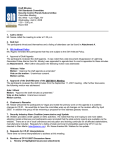
Choose the Trigger Source. Every Trigger Source is determined by an incoming message from
the tracker. In the case of triggering on payloads, the available payload fields are dependent on
the GPS Device Type as some fields are specific to certain devices.
Choose the desired Message Type, Payload Field, Operator and Value. See the screenshot to
see the configuration for a Trigger that will initiate a Datastream if the battery level gets below
50%.
Click Save.
Next, you must create an Action and assign Assets to it.
Figure 3: Create Trigger
Create Action. An Action combines a Delivery Method, a Trigger (or Triggers), and Assets to form a
Datastream.
1.
2.
3.
4.
5.
6.
7.
Select Actions from the Datastream menu. Click Create New Action.
Choose the Device Type of the Action you wish to configure.
Choose the Trigger and/or Triggers you need for this Datastream. Choosing multiple Triggers will
require the choice of Trigger Logic between the two (or more) triggers. “AND” represents all of
the chosen Triggers, “OR” represents any of the Triggers.
Choose the Delivery Method(s) you want to configure to this Datastream.
Save the Action and move to Assign Assets to Action.
Scroll through the list of Assets and choose the Assets you wish to assign to this action. Use the
Ctrl key while selecting Assets to select multiple Assets or use the double arrow button to select
all Assets.
Click Save. You have now created a Datastream.
32 | P a g e
Proprietary and Confidential Revised 10-11-11
Figure 4: Create Action
Figure 5: Assign Assets to Action
Queuing, VAR Back Office Acknowledgement, and Error Notifications
With the use of user defined data transfers it is up to the VAR to make sure data is being received at
the VAR’s back office properly. The Datastream assumes the VAR’s back office is functioning
properly and handling data without error.
Custom defined and future Datastream methods utilize a data queue that can be configured to retry
every sixty seconds in the event of VAR back office failure or error response. Messages will be
transmitted one at a time in a first-in, first-out fashion. It will be the responsibility of the VAR’s back
office to acknowledge accordingly as to whether or not the data was received and handled properly.
33 | P a g e
Proprietary and Confidential Revised 10-11-11
After a set number of failed attempts or error messages an alert will be emailed to an address
provided notifying the VAR of failure.
Custom Defined Methods
Datastreams are capable of defining custom formats, transport layer methods, and
acknowledgement states as defined by the VAR. Methods include but are not limited to: TCP, UDP,
SSL, FTP, SOAP, etc. Data encapsulation formats include but are not limited to: CoT (Cursor On
Target), custom XML schemas, custom binary encoding, etc. Development of custom methods are
subject to the terms and conditions arranged with Numerex.
34 | P a g e
Proprietary and Confidential Revised 10-11-11