1
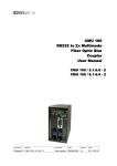
UNIVERSAL ELECTRIC VEHICLE GAUGE AND MONITOR
USER’S MANUAL
COPYRIGHT © 1999-2012 Metric Mind Corporation
All Rights Reserved
Rev. 1.0.08 Aug 20, 2012
this page intentionally left blank
Page 2 of 52
Table Of Contents
Introduction .................................................................................................................................................................4
Standard functions of the EVision. ...........................................................................................................................6
EVision model selection.............................................................................................................................................8
The display color information: ..................................................................................................................................9
The hardware supplied:............................................................................................................................................10
Main controller interface 35 pin AMPSEAL connector pinout..............................................................................18
Shunt measurement PCB .........................................................................................................................................19
Speed sensor wire color specification: ..................................................................................................................20
Interfacing to EVision ...............................................................................................................................................21
Installing and setting up EVision. ...........................................................................................................................22
EVision operation......................................................................................................................................................32
Specifications............................................................................................................................................................44
Glossary. ....................................................................................................................................................................45
Appendix 1 .................................................................................................................................................................48
Appendix 2 .................................................................................................................................................................49
Index ...........................................................................................................................................................................50
Page 3 of 52
Introduction
Thank you for purchasing EVision – universal electric vehicle gauge and monitor. Your EVision is a second
generation of sophisticated and precise measurement instrument – the only one on the market allowing you to
observe at once and track and record so many parameters related to EV performance as well as realize several
vehicle body and drive/charge subsystems control functions. It is designed to work as stand alone instrument and
does not require the presence of a VCU or any other electronic subsystems in the vehicle. However, having
standard CAN architecture for its data traffic EVision can be part of a BMS or other electric vehicle control system1.
Please read this manual before installing and using EVision.
ATTENTION: Even partially charged battery may possess more energy than you may realize. Traction pack voltage
is present on the DC/DC converter section of the measurement board at all times. Observe precaution when
installing and servicing the system. Always connect the HV traction pack last and disconnect it first. Always insulate
exposed hot ends of high voltage wiring when disconnected from the EVision shunt measurement printed circuit
board (PCB). Always disengage jumper shorting precharge resistor prior to high voltage connection and short it
after connection is made (this is relevant for >150 VDC traction battery systems)
The high voltage section of the shunt measurement PCB (EVision power supply) is connected directly to the
traction battery. However, this section is galvanically isolated from all the other sub-blocks, as well as from the
vehicle body. The isolated voltage generated by the power supply on the shunt measurement PCB is 7.5VDC and
2
is used to power HMI PCB and Display PCB.
1
To take advantage of the CAN based architecture, compatible instrumentation must use the same 500 kbps CAN speed as
used by EVision.
2
See glossary on page 41 for definitions and acronyms used throughout this manual.
Page 4 of 52
Introduction (continued)
The RS232C serial port allows monitoring and recording all running parameters as well as configuring the
instrument and upgrading its firmware. It is galvanically isolated from all other circuits including vehicle auxiliary 12V
battery and vehicle body. When an external laptop or PC is connected to EVision to capture data, it can be powered
either from its own battery or directly from vehicle’s auxiliary 12V battery. Connecting a laptop to the RS232 serial
port and capturing streaming data has no impact on the operation of EVision.
The vehicle auxiliary 12V battery is not isolated from the main controller; however it is not being used to power
EVision. All EVision sub-blocks get power from the main traction battery only (via the integrated isolated DC-DC
converter). Auxiliary 12V battery is only required to enable certain modes of operation. Its voltage is only being
monitored and displayed.
You can download the latest version of this manual as well as accompanying software from the
Metric Mind Corporation web site: http://www.metricmind.com/evision.htm
Page 5 of 52
Standard functions of the EVision.
Display (and output to capture) in real time:
For Traction battery
- instantaneous voltage, V
- instantaneous current in or out, A
- Instantaneous power in or out, kW
- Running capacity, Ah
- Running energy, kWh
- Running SOC, %
- Temperature (highest of 2 zones)
- Indication of direction of battery current, OUT (drive) or IN (regenerative braking or charging)
- Cycle life, full cycles
- Pack Imbalance detection and rough measurement
For Auxiliary 12V battery
- Instantaneous voltage (V)
For Vehicle
1
- Energy consumption, Wh/mile and/or miles/kWh
- Distance to empty estimation
- Time to full estimation (in charging mode)
- Optional fiber optic interface to the vehicle Battery Management System (BMS) or other instrumentation
1
Metric units version: Distance – km, Tire pressure – kg/cm2. All related computed values
(e.g. efficiency Wh/[distance unit] ) are scaled for respective units and displayed accordingly.
Page 6 of 52
Standard functions of the EVision (continued).
(continuing):
- Indication of charging status
- Stock analog fuel gauge drive
- Display night time dimming and HMI illumination
- Automatic Sleep mode with wake up on IGNITION ON or CHARGER ON signals
- Power steering pump control via isolated driver circuitry1
Instrument:
- Capture live data streaming from the serial port2
- Download and Upload configuration parameters and upgrading firmware
- Long retention of the internal RTC (Real Time Clock) setup for correct time stamping
Optional functions3 are:
Tire pressure measurement, all 4 wheels4
- Cruise control
- Charger, BMS and other subsystems control via I/O expansion module
1
Using hydraulic power steering pump requires external power driver hardware amplifying control signal.
PC or Palmtop with serial interface and capable of running HyperTerminal required.
Imperial units version: Distance – miles, Tire pressure – PSI
3
Please contact Metric Mind Corporation to find out more regarding available options. Not all options are implemented.
4
Requires supporting hardware.
2
Page 7 of 52
EVision model selection
The ordering code selection matrix for all available options is shown on example below1:
MMC-0500-040-I-999-480-720-540-W-E-3
Fiber optic cable length (m), default is 3m
I = In-dash display
E = External display
N = No main controller enclosure
B = Black enclosure
W = White enclosure
Display color options
Information section color number
25 segment analog bar color number
Lower digital display color number
Upper digital display color number
I = Imperial units
M = Metric units
Charger shunt (battery charging current only) rating
40 = 40A max charging current measurement
100 = 100A max charging current measurement
Main shunt (drive/regen current measurement) rating
0200 = 200A rated current measurement
0500 = 500A rated current measurement
1000 = 1000A rated current measurement
2000 = 2000A rated current measurement
4000 = 4000A rated current measurement
Metric Mind Corporation identifier
1
Please be aware that special custom colors selected from the large palette shown in appendix 1 (page 47) will
affect purchasing price of the unit.
Page 8 of 52
The display color information:
The features of the front overlay are shown below and may aid in selection of the color scheme.
The EVision logo (serving as Power ON indicator) always comes in dark purple color as MMC brand color, and the
alarm symbol “!” is always in red color. All other fields are customizable per user request. Below is one example
how EVision display can be preconfigured for you. You will find all custom colors available for different sections of
display in appendix 1 on page 47.
25 segment analog bar
Upper display and units symbols
Lower display and units symbols
Charger ON symbol
(photo coupler status)
Alarm
Power steering pump ON symbol
Charging status bar
Page 9 of 52
The hardware supplied:
Shunt measurement PCB
(500A main shunt shown)
Display PCB assembly (in-dash type is shown)
HMI PCB
Speed sensor
Main controller PCB
Page 10 of 52
The hardware supplied (continued)
Display to HMI
cable
Main plug
contacts
HMI
knob
Main interface plug
Fiber
optic
cable
“Favorite”
buttons
Thermistors
connector
HV input
connector with
wire seals and contacts
HMI to main controller
cable
Accessories hardware
System power
cable
Cables
A CD-ROM with setup utility, firmware and latest user manual available at the time of release is also supplied.
Optionally, if ordered, the main controller machined plastic enclosure with the controller PCB mounted inside and
external display hood will be supplied.
Page 11 of 52
The hardware supplied (continued)
The EVision LED display unit is supplied either as internal (in-dash) or external (in spherical enclosure). The display
is a microprocessor based device which converts related data on the CAN bus to a form suitable for two
3 digit 7-segment LED displays, units and status LEDs and one 25-segment LED analog bar. As there are no
control buttons or knobs on the display unit, it can be installed in any location where it is easily observed1. The
display unit is equipped with PWM output to drive any stock analog gauge (if it is based on electromagnetic coil
movement rather than stepper motor). Typically a stock fuel gauge is used, in which case EVision output’s PWM
duty cycle can be programmed to output a signal proportional to the battery SOC level.
The main controller PCB consists of microprocessor, galvanically isolated RS232C serial interface, RTC, CAN
transceiver, analog measurement and logic I/Os with signal conditioning circuitry. The main controller handles all
the calculations, and communication with other sub-blocks. The main controller’s vehicle interface consists of an
automotive style AMPSEAL 35 pin connector. Two analog (NTC thermistors) temperature sensors, speed sensor
and various inputs/outputs are interfaced via this connector.
The shunt measurement PCB contains physical shunts, isolated HV DC-DC converter, measurement circuitry
2
converting battery voltages and charging/discharging currents in digital form and a line encoder driving fiber optic
transmitters. Data transmission to the main controller and optional BMS is implemented via a fiber optic cable
allowing exceptional noise immunity as well as safety. The shunt measurement PCB3 is equipped with a HV (High
Voltage) battery connector and LV (Low Voltage) connector used to feed power to the main controller, HMI and
LED display. The shunts must be rated for the continuous average current to be measured. Please note that
electrically shunts can be overloaded up to 2.5 times without loosing accuracy of measurement (e.g. 200 A shunt
will handle 500 A current measurement), however shunts will not tolerate long overload thermally.
1
If external display is installed onto a dash board under wind shield, make sure it is protected from excessive heat. Use optional
plastic hood for better visibility with bright ambient light.
2
Full and half (center tap) battery voltage connections are required for halves comparison function to work.
3
Consult the factory about connecting your BMS to the EVision to take advantage of EVision’s accurate voltage and current
measurements circuits.
Page 12 of 52
The hardware supplied (continued)
For this example it means if your drive system draws 150A from traction battery on average but has excursions
during accelerations up to 400 A, a 200A shunt will be appropriate choice here for as long as current more than
rated 200 A are not exceeded for a long time. “Long time” can be defined as 10-20 seconds to few minutes depending on the degree of overload and cooling conditions. The higher overload and more limited cooling, the
shorter time duration is allowed; the goal is to prevent overheating of the shunts. Charging normally has no current
excursions so if your battery charging current exceeds 40 A, you must use 100 A charger shunt.
The HMI unit controlling EVision is a physically separate unit that allows controlling of a display remotely. Therefore
it can be mounted in any location within easy reach and away from the display unit. The HMI block consists of a
rotary encoder combined with a push button, CAN I/O handler IC, CAN transceiver, few LEDs, a buzzer, the
connector for optional “favorite” buttons and the terminal blocks to connect to the rest of the system.
Supplied speed sensor is Hall-effect based detector with integrated permanent magnet and line driver circuit. It
registers presence of ferrous material (gear teeth like) moving in close proximity to its sensing tip. No moving
magnets required.
Page 13 of 52
The hardware supplied (continued)
Representative diagram of the EVision system integration is shown below. Supplied components are shown in
darker amber color. Note: Connection of non-EVision components (fuses, contactors) on this diagram are shown as
working example only; your implementation of these components does not have to follow it.
Page 14 of 52
The hardware supplied (continued)
Representative diagram of the main controller PCB:
Page 15 of 52
The hardware supplied (continued)
Representative diagram of the shunt measurement PCB:
Page 16 of 52
Representative diagram of the HMI PCB
The hardware supplied (continued)
Representative diagram of the display PCB:
Page 17 of 52
Main controller interface 35 pin AMPSEAL connector pinout
Pin
FUNCTION
number
1
Temp. sensor 2 low
2
Temp. sensor 2 high
3
Temp. sensor 1 high
4
Charger ON
5
Aux2
6
Speed sensor
7
Aux1
8
- Out1 Charger enable
9
+ Out1 Charger enable
10
No connect
11
RS232C GND (DB9 pin5)
12
RS232C OUT (DB9 pin2)
13
- Power IN (System Power return 0V)
14
- Power OUT (System Power return 0V)
15
Temp. Sensor 1 low
16
Speed sensor GND
17
Speed sensor PWR
18
Night dimming (Lights ON)
Pin
FUNCTION
number
19
- Out2 Power Steering Pump control*
20
+ Out2 Power Steering Pump control*
21
No connect
22
No connect
23
RS232C IN (DB9 pin 3)
24
+ Power IN (System Power +7.5V)
25
+ Power OUT (System Power +7.5V)
26
CANH
27
CANL
28
CL30 Kelvin (direct to +12V Aux battery)
29
CL31 Kelvin (direct to -12V Aux battery)
30
CL15 (Ignition ON)
31
No connect
32
No connect
33
No connect
34
No connect
35
Chassis noise reduction (option).
Inputs are listed in blue font color
Outputs are listed in red font color
All other I/Os and power connections are listed in black font color
* OEM option only
Page 18 of 52
Shunt measurement PCB
Pin
number
1
2
A
B
FUNCTION
Connector type, wire color
Traction pack voltage, most positive
½ of traction pack voltage, (center tap)
System Power +7.5V
System Power return 0V
Tyco, ORG
Tyco, YLW
Delphi, RED
Delphi, BLU
HMI PCB connector wire color specification*:
PCB label Function, wire color
PWR
+7.5V power, RED
GND
Power return, BLU
CANH
CAN bus high, ORG
CANL
CAN bus low, BLK
* Either of two terminals designated for the same wire color can be input or output. Both terminals of the same color
are electrically connected together providing pass-through connectivity.
LED Display wire color specification:
Function
PWM output*
+ Power
- Power return
CAN bus high
CAN bus low
Wire color
WHT
RED
BLU
ORG
BLK
*Use of PWM output to drive stock fuel gauge to show traction battery SOC is optional. Cut off this wire if you don’t
intend to use stock fuel gauge as SOC indicator.
Page 19 of 52
Speed sensor wire color specification:
Function
+ Power
- Power return
Sensor output
Wire color
TAN or RED
BLU
BLK
HMI block PCB “favorite” buttons connector specification1:
PIN number
1 (square pad)
2
3
4
1
Function
Favorite page 1 button
Favorite page 3 button
Favorite page 2 button
Common for all buttons
Favorite buttons connection is optional. In some firmware versions this function is not implemented.
Page 20 of 52
Interfacing to EVision
All digital inputs accept +12V as logic 1. They are meant to be used in common standard automotive 12V electrical
system (actual range is 10.5…15V DC) and protected against short transient voltage spikes. Inputs will withstand
about 25VDC of either polarity continuously without damage.
By an accepted in automotive industry signal naming convention, vehicle interface signals are named accordingly:
CL15: to +12V after ignition key (“Ignition ON”)
CL30: to +12V, directly to the battery.
CL31: to -12V, directly to the battery (normally vehicle chassis). Note: Pin 29 of the main controller must be
connected to -12V directly at the battery terminal, not to the vehicle chassis.
Digital inputs interface circuit:
Analog input interface circuit (Aux. 12 V battery voltage measurement):
Page 21 of 52
Installing and setting up EVision.
Important note: single wire interface connectors between EVision PCBs are clamp cage type. While opening the
clamp by moving lever with small screwdriver or fingernail prior to inserting bare wire, support back of the connector
to avoid bending PCB and thus stressing surface mount components. This is especially important for +HV and –HV
connectors on the main controller PCB and components next to the planar transformer.
HMI PCB is equipped with clamp cage solderless connectors for two reasons:
- You don’t need to mount mating connectors on the end of a wire and can cut it to any desirable minimal length
to reduce resistance and noise.
- Unlike screw terminals, spring loaded clamp cage
terminals always put consistent pressure on a wire,
can be mounted without any tools, and once wire is
connected, unlike screw terminals clamp cage
connector has no chance to get loose. Connectors
will accept bare solid or stranded wire. Strip
insulation to expose 5-6mm (0.25”) of the conductor.
Open the clamp by pressing on the lever with finger
nail or flat blade small jewel screwdriver, insert the
wire and release the clamp. That’s it. It is not
necessary to twist exposed stranded wire end, tin it
or crimp ferrule over it prior to insertion.
- Connection of a wire can be done very quickly, no
need to hunt for a slot in a screw, no chance any
parts can get lost (like screws in case of screw
terminal).
Page 22 of 52
Installing and setting up EVision (continued)
Minimum hardware configuration consists of four sub-blocks: shunt measurement PCB, main controller PCB, HMI
and display. All EVision sub-blocks (except for shunt measurement PCB) handle data traffic via CAN bus. The
shunt measurement PCB transmits data to the main controller PCB via fiber optic cable.
•
Pick location for the main controller. Mounting orientation of the main controller is not critical; however avoid
close proximity to the battery cables and other high noise level conductors. Optional machined plastic enclosure
(as shown below) is highly recommended as 35 pin AMPSEAL connector requires high force to plug in and
there are no means to attach main controller PCB to any surface other than using its connector’s flange.
Convenience of routing wiring harness to and from the main controller should be considered for optimal
physical placement. There are no serviceable parts inside and the only event user should access the main
1
controller is to monitor internal LEDs for troubleshooting and to provide global reset . The main controller PCB
is held by 4 screws supporting AMPSEAL interface connector and holding halves of enclosure together. Two
more screws (long and short) inserted from the top. All
this hardware is included.
•
Pick location of HMI block on the dash or central console
within convenient reach. Control of the EVision operation
is achieved solely by only one knob on the rotary encoder
with a push-button. Only Power and CAN bus connection
is required to interface HMI block with the rest of the
system.
1
Global reset re-initializes all variables to the factory pre-set values
and wipes out any stored historical data such as total charge cycles
counter or hardware related data such as speed sensor pulses/rev
amount, shunt value, voltage and temp. limits, PWM settings, etc.
Page 23 of 52
Installing and setting up EVision (continued)
Note: Since electrically HMI must tap the CAN bus, the HMI interface connects inline with 4 wire harness. This
means 4 wires go in, make contact with HMI and come out (8 wires total). It is possible to have a spur off the bus
(no longer than ~30 cm) in which case only 4 physical wires will be connected to the HMI connector block (either
side). Remaining 4 terminals in this case will be unused. Wire color is silk screened on the HMI PCB.
•
•
•
•
•
•
•
Choose location for the display unit. Globe display is installed on dash or A pillar while internal in-dash display
is typically integrated into the stock instrument cluster. A wire harness permanently attached to the display has
standard length 1m and in case it cannot reach HMI block, can be extended.
Connect display harness (4 wires, see color table) to the HMI PCB using its clamp cage terminal connectors.
Shorten the harness as needed. Wire color next to each connector is silk screened on the PCB.
Connect HMI block to the main controller using supplied 4 wire harness. There are two terminals for each color,
they are connected together so there is no “input” or “output” side of the HMI.
Connect + and – of the auxiliary 12V battery to the main controller.
Note: This is Kelvin connection. While negative terminal of the auxiliary battery is typically connected to the
vehicle body, grounding -12V wire from the main controller instead of running dedicated wire directly to the
negative terminal of 12V aux. battery will inevitably introduce an error to its voltage measurement. Always use
dedicated wires going from the main controller directly to the auxiliary battery terminals.
Connect the rest of the inputs/outputs of the main controller PCB according to the pinout in the table on page
18.
Connect one or both temp sensors (included 2.7k NTC thermistors) to the main controller PCB. Having temp
sensors is optional. Mount each sensor in any two places expected to have highest temperature you want to
measure. Use pair of twisted wires, they don’t have to be shielded.
Connect speed sensor. Having speed sensor hooked up is optional, however without it some functions related
to distance or speed will not be available (speedometer, odometer, Wh/mile or Wh/km drive efficiency, DTE
range estimation, etc.
Page 24 of 52
Installing and setting up EVision (continued)
•
Mount shunt measurement PCB. Since the shunt is inserted in the negative battery cable, attempt to place the
PCB in the former path of negative battery cable to minimize extra length of the cable. The main shunt has
threaded mounting holes and is expected to be mounted on insulating base. The charger shunt does not
require own support. However, the measurement PCB does requires its support through two mounting holes
marked as M4 (which is the size of the mounting post or screw thread). Note that the measurement PCB
CANNOT rely to be held in place by being bolted only to the main shunt – the weight of the charging shunt, its
cable and planar transformer will cause excessive vibration of the PCB, loosen planar transformer and
premature failure of the power supply. It is mandatory to support at least one corner of the left side of the shunt
measurement PCB with metal or plastic stand-offs or supporting brackets.
Note: shunts may become warm during normal operation and power supply components may become hot.
Therefore make sure the shunt measurement PCB has adequate cooling. The shunt PCB comes without its own
enclosure as it is intended to be mounted either inside the main contactors box or in the power distribution box with
enough air circulation for convection cooling. Should you choose to install this PCB in a small individual enclosure,
DO NOT use sealed enclosure that does not have ventilation holes or forced air cooling. Best option is to install the
unit in a way of adequate air flow or use small muffin fan (sold as a CPU cooling fan) for forced air cooling.
•
Interconnect the shunt measurement PCB and the main controller with fiber optic cable. If it is necessary to cut
the cable to a shorter length, place cable on a piece of wood and make a straight cut at right angle with a sharp
knife in one quick motion. DO NOT use wire cutters to cut fiber optic cable. Loosen plastic barrel and insert
fiber as far as it will go (about 16mm). Do not make fiber cable shorter than 2.5 meters as it might saturate
optical receiver.
•
Link both bottom terminals of both shunts with flat strip of copper or a wire jumper. The crossection of the link
should be adequate to pass maximum charging current.
Page 25 of 52
Installing and setting up EVision (continued)
•
Connect traction current shunt in series with the traction battery. If the vehicle is already equipped with shunt
installed in the negative cable of the traction battery, replace it with EVision provided shunt or connect EVision
shunt in series. The top of the shunt must be connected directly to the most negative terminal of the traction
battery. If the vehicle does not have any instrumentation and the power cable from the negative terminal of the
traction battery is connected directly (or through the contactor) to the traction controller or inverter, this cable
must be cut and resulting cable ends fitted with crimp-on ring terminals. Diameter of the ring hole depends on
the supplied shunt type.
ATTENTION: As indicated by silk screening, even though traction and charging shunts are connected by a copper
trace, you MUST link both these shunts externally with a wire jumper or braded grounding strip with enough
crossection to handle maximum charging current. If rigid link is used, make sure it is flat and placed directly on top
of both shunts to avoid warping the PCB. Failure to perform this step will cause PCB copper trace to overheat
during charging and in case of high charging currents - to burn out. Such failure is hazardous as may lead to
melting insulation of near by wiring, further causing electrical shorts and possibly a fire. User assumes and accepts
full responsibility for the consequences of not following this step. You also should connect the lug of the cable
coming from the negative terminal of the battery directly to the larger (traction) shunt and make a link from this
connection to the smaller (charging) shunt, not the other way around. Not following this requirement may introduce
large error in driving and regen current measurement.
•
Connect charger negative DC output in series with charger shunt.
Optional: Prepare a yellow wire (not supplied) with enough length to extend from electrical middle of the traction
pack to the shunt measurement PCB. Install inline 20…100 mA DC rated fuse. This type of fuse is used in hand
held multimeters. At the end of wire insert supplied wire seal, crimp supplied contact terminal and insert it into
Page 26 of 52
Installing and setting up EVision (continued)
contact 2 of Tyco connector according to specification on page 19. The wire crossection is around 1.5mm2 (AWG
gauge 20…18). Do not connect the other end to the traction battery yet.
•
Prepare a red wire (not supplied) with enough length to extend from the most positive terminal of traction pack
to the shunt measurement PCB. Install inline 20…100 mA DC fuse. Leave precharging resistor (inserted into
the orange wire coming from HV connector and fitted with shorting jumper wires) electrically inline, e.g. do not
connect jumpers together yet). Once EVision is working, the only time you will ever need to break shorting loop
around precharging resistor is if you ever disconnect EVision from the traction battery for battery maintenance.
Normally EVision is powered at all times. Insert the supplied wire seal on the end of the wire, crimp the contact
terminal and insert it into contact 1 of supplied Tyco connector according to specification on page 19. Do not
connect the other end to the positive terminal of the traction battery yet.
You can use representative schematic on page 14 as a reference for all the connections, but your particular
configuration will depend on whether you have one or two main contactors, reversing contactors (for DC system),
on your particular precharging circuitry configuration, etc.
There are no power switches as EVision must be powered up at all times to track energy consumption while idling
and to retain valid date/time set up in RTC. When the vehicle is idle, display enters sleep mode reducing power
consumption from the traction battery, but it remains fully functional and tracks idle energy consumption at all times.
Display wakes up and serial connection activates on any user input such as ignition on, lights on, charger on,
button press, etc. Proper hook up sequence is: While in sleep mode, purple “EVision” logo at the bottom of display
is illuminated indicating that the traction battery is live and connected.
At this point the proper sequence of powering up the unit is:
•
Mate low voltage Delphi connector (red and blue wiring).
Page 27 of 52
Installing and setting up EVision (continued)
•
•
•
•
Connect orange wire from HV connector to the positive terminal of the traction battery.
Mate HV power connector. EVision will precharge and turn on. Display will wake up and turn on. Depending on
the status of digital inputs it may stay on or will go to sleep within 30 seconds.
Short out precharge resistor by mating “quick connect” terminals of jumper wire.
Connect yellow wire to the electrical middle of the battery pack.
The EVision logo will lit. EVision is ready for operation.
Page 28 of 52
Installing and setting up EVision (continued)
Should you need to disconnect the instrument, just unplug HV connector. Then disengage the jumper terminals
around precharge resistor. You can leave orange and yellow wires connected to the traction battery.
To reconnect the instrument, just plug HV connector and short the precharge resistor with its jumper wires.
The mid pack connection does not require precharging.
ATTENTION: if for whatever reason EVision looses main power, you must precharge the circuit every time you
connect traction power to the HV connector, and observe the required sequence of powering up as described on
the page 27. Failure to comply with this requirement for voltages more than about 150 VDC will result in too fast
voltage rise at the moment you connect EVision directly across high voltage battery and this may damage power
supply IC. Such damage has distinctive signature and is not covered by manufacturer’s warranty.
You can use representative schematic on page 12 as a reference for all the connections, but your implementation
depends on the controller/inverter type, contactor type, battery arrangement (if split in few sections) etc., and will
vary.
If there is no active signal on any input of EVision, it will enter power saving sleep mode after 5 seconds of
inactivity. Data streaming via serial port will cease until display is woken up. However, EVision will keep track of Ah
in or out of traction battery while in sleep.
Page 29 of 52
Installing and setting up EVision (continued)
Preferred proper way of connection
Wrong way – long spur (>30 cm)
off CAN bus is not allowed.
Acceptable way (short spur and splice to CAN bus)
Page 30 of 52
Installing and setting up EVision (continued)
To enhance a readout for external display under bright ambient light, a visor or small hood is recommended:
Page 31 of 52
EVision operation
There are 2 modes of operation of EVision:
•
•
Running mode
Set up / firmware download mode
After powering up and initializing EVision defaults to the page 1 display. Keep in mind that if no active input signals
are present (IGNITION ON or CHARGING ON), the system enters sleep mode 30 seconds later. If the system was
powered up already and ignition input and charging input went inactive, EVision goes to sleep 5 seconds later.
Communication via serial port while in sleep is ceased and is not possible. You can wake up the unit to check out
values without ignition or charging signal by pressing HMI button.
As factory default, page 1 simultaneously shows full battery voltage on the upper digital display, battery current on
the lower digital display and the state of charge on the 25 segment analog bar. There are 20 pre-defined pages
user can select by rotating HMI knob. All measurable parameters are internally tracked and outputted via serial port
in real time, user only selects which 3 parameters are being displayed as a group per page. All default pages are
1
user definable: any 3 parameters can be assigned to each of 20 pages to suit your preferences . Once set up,
2
pages contents is stored in non-volatile memory so next time EVision wakes up you only have to choose which
page to display by scrolling through them rotating HMI knob CW or CCW. If implemented and enabled, you can
recall first 3 pages using 2 or 3 “favorite” buttons connected to the HMI PCB.
1
You should only select combination of parameters that have corresponding units next to respective displays
For instance you should not choose battery current on upper display and vehicle speed on lower display on the
same page since unit symbols for both of these parameters (“A” and “km/h”) are located next to lower display. If you
configure unit this way, numerical Amperes value will be displayed correctly on the upper display and speed on the
lower display, but both “A” symbol and “km/h” symbol for units will lit next to lower display only.
2
If you press global reset button on the main controller, factory defaults will get restored, including favorite pages.
You will have to redefine your own pages over again.
Page 32 of 52
EVision operation (continued).
To change displayed page simply rotate HMI knob SW or CCW. Each click selects next or previous [pre-defined]
page. After waking up from sleep mode it may take up to 4 clicks of HMI encoder button in any direction to re-sync
the encoder. The page number WILL NOT advance during re-synchronization; this is not a malfunction.
Currently initial configuration of display pages for later selection is only possible via serial port from a PC.
The serial port is PC standard RS232C port with communication parameters fixed to 19,200 baud, 8 data bits 1
stop bit, no parity, no flow control. If a PC does not have RS232C serial port, communication is possible with any
standard USB to serial adapter. In this case comm. port number you select in GUI has to match serial port number
Windows has assigned to the USB adapter (check Device Manager). Alternatively, any terminal program can be
used, such as HyperTerminal for PC platform running Windows or z-terminal for Macintosh platform. Once a PC is
connected to EVision and communication established, pressing “0” (zero) key ten times invokes built in
upload/download utility. Setting up Display and SOCM parameters consists of downloading configuration file to a
PC, modifying its contents and uploading back to EVision. However, be advised that manual editing of the config.
file is somewhat involved and is not recommended.
Should EVision get out of sync with actual known capacity of the battery, it can be reset to 100% SOC by pressing
down and holding HMI button for >5 seconds. However, EVision resets itself every time amount of charge
replenishing traction battery exceeds amount of charge taken out on the previous cycle.
The supplied EVM (Electric Vehicle Monitor) program has GUI that is used to configure EVision and upgrade its
firmware. See contents of included CD-ROM disc. Latest documentation and firmware can always be downloaded
from Metric Mind Corporation web site and may supersede version available at the time of CD release.
Page 33 of 52
EVision operation (continued)
To establish serial connection, choose from drop down list the port number EVision is connected to, see picture
below:
After clicking “Connect” button communication will get established, data start scrolling through the terminal window
and running parameters in GUI will get populated with live data.
Enter System set up mode (View -> Main Controller set up or View ->Display setup). In this window you set shunts
values, wheel diameter, default efficiency (in case no speed sensor used), alarms limits and other parameters. See
main controller configuration GUI overview on page 35 and display controller – on page 38.
Page 34 of 52
EVision operation (continued).
GUI interface overview. Main page
Status of the system
Live data - can be captured to a file
Page 35 of 52
EVision operation (continued).
GUI interface overview. Main controller configuration page
In effect only if no speed sensor is connected
w
Shunt selection, must
match physical shunts installed
Always In effect
Optional external
connection for charger
Setting to “0” disables this function
External hardware required
The power steering control function is available in OEM version only
Page 36 of 52
EVision operation (continued).
While configuring your EVision, please keep in mind following points:
- “Max. Battery Voltage” selection must match option supplied (selected on the shunt measurement board).
If traction battery voltage exceeds 450VDC at any time, “HV” option must be activated. Contact MMC tech. support
for assistance.
- Declared usable pack capacity must not exceed total rated capacity. See appendix for definitions.
- Total Charge timer is safety feature in addition on any timers your charger might have. After preset amount of
hours elapse, optocoupler changes state to the opposite from its preconfigured default state during charge. You can
use this coupler to control a relay (solid state relay preferred) to disconnect your charger from the mains.
- “CV time to full” value is amount of hours between the time the bulk charging is completed (charging transitions
from CC to CV mode) and end of charge time. CV mode is assumed to start at 75% SOC. CV time depends on your
battery model and has to be calibrated once (observed and inputted here). This amount is always constant and is
not dependent of the running SOC.
To estimate TTF (Time To Full) the charger will compute amount of time needed to complete bulk charging e.g.
reach 75% SOC (based on present SOC and rate of charge) and will add CV time you define in GUI. Should you
interrupt charging during CV mode, re-plugging charger back will initialize TTF to CV time even though CV time was
partially completed. EVision does not keep track how long CV mode lasted before interrupted, so accurate TTF
estimation under these circumstances is not possible.
- “Ah reset threshold” is in effect only if some amount of deliberate overcharge is allowed and actually takes place.
If the SOC is 105% (you deliberately put in 5% more Ah than you spent since last full charge so the amount of Ah
spent shows negative), as soon as you start driving and battery current exceeds defined here value, SOC meter
resets to 100% and Ah spent – to zero. You also can always initialize EVision to this condition by pressing and
holding down HMI button for about 5 sec (until you hear beep).
Page 37 of 52
EVision operation (continued).
-
For the speed sensor – do not output more than 2 pulses per rev of the shaft if rotation speed is more than
about 2000 RPM. For a wheel shaft typical rotation speed (at freeway vehicle speed) does not exceed 1000
RPM so you can use 4 pulses per rotation. For slow shafts, to increase accuracy at very slow speeds, output
6…8 pulses per revolution. For direct drive vehicles you can install speed sensor on the motor shaft instead of
the wheel shaft. In this case fill in differential R&P (final drive) gears ratio.
On the display configuration page, besides pre-configuring pages, you can set amount of display dimming in night
mode. Drag the slider left or right and write settings to EVision. Experiment with different settings. Dimming occur
when “Night” control input of the main controller receives +12VDC. This is easily accomplished by connecting this
input to the vehicle’s side marker light bulb.
You can drive stock fuel gauge with EVision – this will
resemble familiar FULL - EMPTY readout of the fuel gauge
corresponding to 100%-0% SOC of your traction battery.
The fuel gauge movement must be of electromagnetic type
(mA meter), not stepper motor drive. Max current EVision
can supply is about 30mA. Initial (“E”) and final (“F”)
position of the gauge pointer can be finely set up by
adjusting PWM of the gauge driver in GUI – drag sliders left
and right until E and F pointer position match 0% and 100%
SOC respectively. In case there is no enough current to
make pointer display “F” even at 100% PWM, you can short
out current limiting resistor marked “DRV BOOST” on the
display driver PCB. This resistor is the only through hole
component mounted for that reason.
Page 38 of 52
EVision operation (continued).
GUI interface overview. Display configuration page
Page 39 of 52
EVision operation (continued).
If factory default settings need to be restored, press and hold reset button on the main PCB (not HMI PCB) for 5
sec.
Warning: all historical and vehicle related data such as preset battery capacity, cycle counter or wheel diameter will
be lost and reset to the factory default values.
Note: The analog bar does not display units symbol associated with parameter.being displayed. Typically analog
bar is used to show relative SOC (0…100%), but if you choose to use the bar on some pages to display other
parameter such as instant power or efficiency, you will have to remember your choice.
Upgrading firmware
We constantly work on the improvements of the instrument and new firmware releases are periodically posted on
the Metric Mind Corporation web site (http://www.metricmind.com/evision.htm) free of charge. You can download
new version and upgrade your EVision. You will need to connect your PC’s serial port to the board you’re upgrading
(main controller or display). If your PC is not equipped with serial interface port, you can use common USB-Serial
adapter.
Both, main controller PCB and Display PCB, are equipped with serial interface, however only main controller has
physical harness and DB-9 serial connector. User is not expected to upgrade display controller since instrument
functionality is solely determined by the firmware running in main controller. The display firmware only contains
LEDs multiplexing and CAN handling routines and will not affect functionality. In case relevant display update
becomes available, please contact Metric Mind Corporation support for any upgrades you may plan.
The serial communication parameters should be set to 19200 baud, 8 bits, no parity check, 1 stop bit, no flow
control. In supplied EVision GUI go to Tools menu and select the Main Controller or Display as shown on the next
page.
Page 40 of 52
EVision operation (continued).
Navigate to the folder containing the firmware file, and while serial port is connected, click OK. (Note - you have to
double-click on the folder name containing firmware to actually open it for GUI to search for the firmware file. Single
click will highlight the folder, but will not open it, GUI will not be able to find the file and upgrade will fail.) Upgrading
will start.
Please note: “Calibrating EVision” function is meant for factory use only even though the menu selection is made
available to the user. Invoking this function requires special software tools; otherwise it will corrupt data in the
program memory. This situation can only be rectified by re-flashing bootloader firmware at the factory and is not
covered by manufacturer warranty. Please DO NOT INVOKE “Calibrating EVision” function.
Page 41 of 52
EVision operation (continued).
Once download is completed, EVision will reset and new firmware will take effect.
Note: Do not attempt to use in-circuit debugger to access the firmware directly through ICSP pads – this is for
factory use only. The firmware has been written to be upgradable through the serial interface only. Any attempts to
read protected the contents of the memory will corrupt the bootloader preventing unit to initialize and thus rendering
it inoperable. Repair of units subjected to direct memory access via ICSP can only be done at the factory by reflashing the program memory. This condition has distinctive signature and is not covered by the manufacturer’s
warranty.
Page 42 of 52
EVision operation (continued).
Capturing and saving live data to a file.
The serial interface continuously streams out all measured and computed data whether acknowledged/captured or
not. Exception is sleep mode when data streaming is suspended to reduce energy consumption.
Output data format conforms to NMEA standard, which essentially is sequence of human readable strings of plain
ASCII characters where each string has identifiers and few other fields. This makes it easier to align, sort and plot
captured data once it is imported into a spreadsheet program such as Microsoft® Excel or similar.
A sample of EVision output is shown below:
………..
$RV,23:17:22,May-28-2007,611,+0.00,+9999.99,+0.01,+0.11,+0.12
$IV,23:17:23,May-28-2007,612,+356.36,+177.24,+0.00,+1.10,+0.30
$RV,23:17:23,May-28-2007,612,+0.00,+9999.99,+0.01,+0.11,+0.12
$CV,23:17:23,May-28-2007,152,+356.93,+177.23,+0.00,+1.12,+4.09,+86.00,+1.00,0
$AV,23:17:23,May-28-2007,152,+14.20,-26.62,-28.46,1,1,0,0,0,0,0,0
$SV,23:17:23,May-28-2007,15,3,5,1,3,255,255,255,255,255,255,255,255
$IV,23:17:23,May-28-2007,613,+356.39,+177.18,+0.00,+1.07,+0.30
Refer to the information on the web site for detailed format and field’s definition:
http://www.metricmind.com/evision.htm
Page 43 of 52
Specifications
Absolute maximum traction battery voltage range
Auxiliary battery voltage range measurement
Traction Battery drive/regen current measurement
Traction Battery charging current measurement
Traction Battery capacity measurement
Traction Battery energy storage measurement
Traction battery power measurement
Traction Battery SOC measurement
Digital inputs voltage
Temperature measurement
Charge cycles counter
Energy efficiency (computed)
Power consumption from the traction battery
Basic accuracy
Digital displays
Analog bar
Working temperature range*
60…800V continuous, 900 VDC peak
0…16 V
+/- 0.1…4,000 ADC (with right rating shunt)
+/- 0.1…100 ADC (with right rating shunt)
0…999 Ah
0…999 kWh
+/- 0…650 kW
0…125%
+10.5…16 VDC
-18°C…+75°C, (0°F…+75°F)
65,536 cycles
0…999 Wh/mile (Wh/km)
5.25W (15mA @ 350VDC) in operating mode,
3.15W (9mA @ 350VDC) in sleep mode
1% of top scale for each value
Two 3.5 digits, max readout: +/- 1999
25 segments, linear or log scale (selectable)
0ºC …75ºC (32ºF…167ºF)
*The system will work at sub-zero temperatures, at least down to -10ºC (14ºF) but the accuracy may be degraded.
Page 44 of 52
Glossary.
DTE – Distance To Empty – projected distance at present consumption rate the vehicle can cover, at which point
the battery is declared empty (usable capacity SOC = 0)
Depth Of Discharge – opposite of SOC – amount of charge (% of full) necessary to completely (re)charge the
battery to 100% SOC. For instance 80% DOD (which is 20% SOC) requires replenishing 80% of useful capacity
back to the battery to reach “battery full” condition (100% SOC).
TTF – Time To Full – Projected time at present charging rate required to completely (re)charge the battery to usable
capacity = 100% SOC
SOC [Battery] State Of Charge, expressed in percentage of either declared usable or real capacity.
DOD – [Battery] Depth Of Discharge, opposite of SOC. When SOC is 0%, DOD is 100%, and vice versa.
SOCM – State Of Charge Monitor. In the context of this manual – main controller PCB.
Usable Capacity (Ah) – portion of total real capacity (specified by the battery manufacturer) user choose to declare
as available for use. When this amount of Ah taken out of fully charged battery, the battery reported to be empty
(SOC = 0%). Usable capacity must not exceed total capacity. Depending on customer priorities, there is optimal
compromise between total energy output available each discharge cycle and total battery cycle life. Usually
declared capacity is set between 50% of real capacity specified at 1 hr discharge rate (lead acid battery) and up to
90% (lithium based battery). For instance total battery capacity specified by manufacturer is 80Ah. User does not
want to discharge the battery deeper than 50% e.g. take out more than 80*0.5=40Ah. So usable capacity declared
to be 40Ah. Once 40Ah are taken out, SOC meter reports 0% remaining, as if no more energy is available for
driving. 40Ah will be used to calculate DTE and TTF. This safeguard guarantees that user will not inadvertently
over-discharge the battery beyond chosen maximum DOD. In this the example when SOC display reads = 0%
Page 45 of 52
Glossary (continued)
(40Ah is taken out of fully charged battery), the battery actually still possess another 40Ah which could be used. In
this case EVision only makes user aware that the battery is being drained beyond chosen maximum.
Usable capacity concept allows avoiding available capacity correction due to Peukert effect.
Degree of Peukert effect depends on the particular battery properties and is specified by the manufacturer as
Peukert exponent. It is very pronounced in lead acid batteries but to some degree exists in any type of batteries
including lithium based. In general, because driving pattern for present cycle is not known ahead of time and near
100% DOD should never be allowed, specifying useable capacity less than full (manufacturer rated) capacity not
only helps avoiding overdischarge and extending battery life but also allows avoiding unpredictability of DTE
readout.
Total REAL capacity – capacity in Ah at EV discharge rate (usually 1 hour) specified by the battery manufacturer for
100% DOD. Beware that typically manufacturers specify total capacity at 20 hours discharge rate.
RTC – Real Time Clock – internal clock maintaining current year, month, day, hour, minute, second and 1/100’s of
a second information, used to time stamp data streaming out of serial port.
HMI – Human-Machine Interface. In case of EVision refers to the control sub-block containing rotary encoder, push
button, alarm and night illumination LEDs and buzzer.
GND – Ground, typically connection to the vehicle chassis potential.
CAN – Controlled Area Network
CANH - CAN interface line driven HIGH during dominant bit transmission
CANL - CAN interface line driven LOW during dominant bit transmission
Page 46 of 52
Glossary (continued)
This page is intentionally left blank
Page 47 of 52
Appendix 1
Standard display colors selection user can specify by a number for different sections of the front overlay:
Full set of colors available as special order. Be aware that dark and dense colors will reduce apparent brightness.
Page 48 of 52
Appendix 2
Default WARM and COOL display themes.
Warm Display
Cool Display
Page 49 of 52
Index
2
25 segment .....................8, 9, 31
D
M
3
Delphi connector .....................27
digital inputs ............................21
main controller ...5, 8, 11, 12, 15,
22, 23, 24, 25, 31, 33, 37, 39,
44
main controller PCB................ 12
Measurement PCB ................. 12
35 pin AMPSEAL connector ...23
E
A
EVM ........................................32
Alarm.........................................9
Auxiliary 12V battery .......5, 6, 24
F
E
EVM ........................................32
factory default ...................31, 39
Favorite buttons ................20, 31
fiber optic cable.................12, 23
B
G
Global reset.............................23
BMS ........................................12
H
C
clamp cage........................22, 24
color scheme.............................9
CV mode .................................36
HMI block ................................13
HMI knob...........................31, 32
L
LED display.............................12
Page 50 of 52
O
opto coupler ............................ 36
P
Power consumption ................ 43
precharging.................25, 26, 27
R
REAL capacity ........................ 45
RS232C ............5, 12, 18, 32, 42
S
serial communication .............. 39
Index (continuing)
T
serial port... 5, 28, 31, 32, 39, 40,
42, 45
shunt 4, 8, 16, 23, 24, 25, 26, 33,
36, 43
Speed sensor ................... 10, 18
temp sensors...........................24
stock fuel gauge ............... 12, 37
Page 51 of 52
U
USB...................................32, 39
Notes
Notes
Page 52 of 52