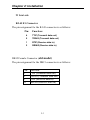
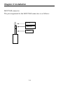
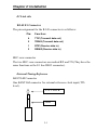
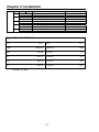
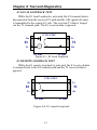
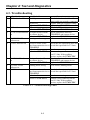
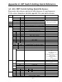
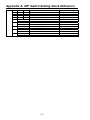
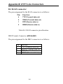
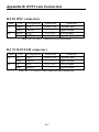
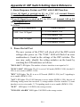
1
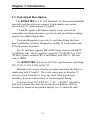
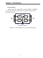
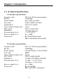
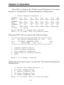
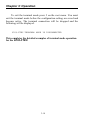
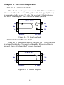
USER MANUAL G703FTEC T1/E1 Cross Rate Converter CTC Union Technologies Co., Ltd. Far Eastern ViennaTechnology Center (Neihu Technology Park) 8F, No. 60 Zhouzi St. Neihu Taipei 114, Taiwan G703-FTEC T1/E1 Cross Rate Converter, Installation and Operation Manual April 2005 (Third Printing) Version 1.04 This manual supports the following models: G703-FTEC/AC 100~240VAC model G703-FTEC/DC +/-24~+/-48VDC model This manual includes the updates for functional firmware version 11.0 and below, including installation and operation of the Terminal Mode. All specifications are subject to change without any further notice. Table of Content Chapter 1: Introduction 1-1. Functional Description 1-2. Typical System Application 1-3. Timing Considerations 1-4. Technical Specifications Chapter 2: Installation 2-1. General 2-2. Site Preparation 2-3. Mechanical Assembly 2-4. Electrical Installation 2-5. Dip Switch Setting Chapter 3: Operation 3-1. General 3-2. Controls and Indicators 3-3. Operating Procedure 3-4. Terminal Mode Operating Procedure Chapter 4: Test and Diagnostics 4-1. General 4-2. Loop Back Tests 4-3. Troubleshooting Table of Content Appendix A: DIP Sw. Setting Summary A-1. ALL DIP Switch Setting Quick Reference A-2. DSW1 Setting E1 Time Slot 1-7 Idle or Active A-3. DSW2 Setting E1 Time Slot 8-15 Idle or Active A-4. DSW3 Setting E1 Time Slot 16-23 Idle or Active A-5. DSW4 Setting E1 Time Slot 24-31 Idle or Active A-6. DSW5 Setting T1 Time Slot 0-7 Data or Voice A-7. DSW6 Setting T1 Time Slot 8-15 Data or Voice A-8. DSW7 Setting T1 Time Slot 16-23 Data or Voice A-9. DSW8 Setting T1 Parameters A-10. DSW9 Setting E1 Parameters A-11. DSW10 Setting Timing Source and E1 Parameters Appendix B: E1/T1 Line Connectors B-1. DB-15 Connector B-2. E1 BNC Connectors B-3. T1 Bantam Connectors Appendix C: Rack Mounting Instructions Appendix D: Signal Transfer Addendum Chapter 1: Introduction 1-1. Functional Description The G703-FTEC is a T1 (US Standard) /E1 (European Standard) converter and timeslot cross connect which enables conversion between one T1 signal and one E1 signal. T1 and E1 signals with frames employ u-Law and A-Law compander encoding principles respectively and encode those analog signals into 64kbits digital data. Tests and diagnostics can easily be performed from the front panel pushbutton switches. Diagnostics include T1 local/remote and E1 local/remote loop back. The T1 interface supports D4 or ESF frame formats with B8ZS or AMI line code. The E1 interface supports CCS (PCM31) or CAS (PCM30) frames without CRC-4 and frames with CRC-4. The line code is HDB3. The G703-FTEC fully meets all T1/E1 specifications, including ITU G.703, G.704, G.706 and G.711. Multiple clock source selection provides maximum flexibility in connecting both T1 and E1. The clock source may be from the T1 recovery clock, from the E1 recovery clock, from the internal oscillator, from an external clock or via transparent timing. It operates from 110~240VAC, +/-24~ +/-48VDC. The unit is built in a compact case that can be placed on a desktop, shelf or installed, by means of an optional adapter, in a 19 inch EIA rack. 1-1 Chapter 1: Introduction 1-2. Typical System Application In a typical application (Figure 1-1), The G703-FTEC is used to connector the T1 line to the E1 transmission facilities. Figure 1-1 Typical applications 1-3. Timing Considerations The eight timing options provide for flexible system timing. This section presents typical applications for each timing mode and considerations that influence the selection of each mode. Transparent timing In this mode, the clock signal recovered from the E1 signal by the G703-FTEC is used as a reference for the T1 transmit clock generation circuits. The clock signal recovered from the T1 signal by the G703-FTEC is used as a reference for the E1 transmit clock generation circuits. G703-FTEC Tx Rx E1 T1 Tx Rx E1 Side T1 Side Transparent Timing Transparent Timing Figure 1-2 Clock signal flow transparent timing mode 1-2 Chapter 1: Introduction Loop Back timing In this mode, the clock signal recovered from the E1 signal by the G703-FTEC is used as a reference for the E1 transmit clock. The clock signal recovered from the T1 signal by the G703-FTEC is used as a reference for the T1 transmit clock. G 703-FTEC Tx Rx E1 T1 Tx Rx E1 Side T1 Side Loop B ack Timing Figure 1-3 Clock signal flow in loop back timing mode T1 recovery timing In this mode, the clock signal recovered from the T1 signal by the G703-FTEC is used as a reference for the E1 and T1 transmit clock generation circuits. G 703-FTEC Rx Tx E1 T1 Tx Rx E1 Side T1 Side T1 Recovery Figure 1-4 Clock signal flow in T1 recovery timing mode 1-3 Chapter 1: Introduction E1 recovery timing In this mode, the clock signal recovered from the E1 signal by the G703-FTEC is used as a reference for the E1 and T1 transmit clock generation circuits. G 703-FTEC Rx Tx E1 T1 Tx Rx E1 Side T1 Side E1 Recovery Figure 1-5 Clock signal flow in E1 recovery timing mode Internal timing In this mode, the internal oscillator (1544Khz or 2048Khz) of the G703-FTEC provides the reference clock for the T1 and E1 transmit clock generation circuits. G 703-FTEC Tx Rx E1 T1 Tx Rx Internal E1 Side T1 Side Internal Timing Figure 1-6 Clock signal flow in internal timing mode 1-4 Chapter 1: Introduction External timing In this mode, the external TTL clock (1544Khz or 2048Khz) provides the reference clock for the T1 and E1 transmit clock generation circuits. G 703-FTEC Rx Tx E1 T1 Tx Rx External E1 Side T1 Side External Timing Figure 1-7 Clock signal flow in external timing mode 1-5 Chapter 1: Introduction 1-4. Technical Specifications T1 interface specifications Complies with: Bit rate: Frame format: Line code: Equalization: Voice channel sample rule: CRC check: Impedance: Transmit pulse level: Receive signal level: Connectors: ITU-T G.703 Recommendation 1.544Mbps D4 or ESF selectable AMI or B8ZS selectable 0-655 feet settable u-Law CRC-6 (when ESF) 120 Ohm balanced +/-3.0V (10%) 0 to –36dB RJ-45 and Bantam jack DB15 and Bantam (old model) E1 interface specifications Complies with: Bit rate: Frame format: Line code: Voice channel sample rule: CRC check: Impedance: Transmit pulse level: Receive signal level: Connectors: ITU-T G.703 Recommendation 2.048Mbps CAS (PCM30) or CCS (PCM31) HDB3 A-Law CRC-4 enable/disable 75 Ohm or120 Ohm selectable 75 Ohm +/-2.37V (10%) 120 Ohm +/-3.0V (10%) 0 to –30dB RJ-45 and BNC DB15 and BNC (old model) 1-6 Chapter 1: Introduction Timeslot mapping selectable E1 CAS mode: E1 CCS mode: TS1-TS15, TS17-TS31 any 24 timeslots TS1-TS31 any 24 timeslots Timing source Transparent Loop back timing Internal oscillator timing 1544KHz Internal oscillator timing 2048KHz E1 recovery timing T1 recovery timing External 2048KHz External 1544KHz Elastic buffer Buffer length: Underflow: Overflow: 2 T1 frames A frame of data was repeated A frame of data was deleted Unconnected codes FF Hex code (all ones) on unused timeslots 1-7 Chapter 1: Introduction Alarm responses Received impairment on E1: Loss Of Signal Transmitted response on E1: Remote Alarm Indication (RAI) Transmitted response on T1: Yellow Alarm Received impairment on T1: Loss Of Signal Transmitted response on T1: Yellow Alarm Transmitted response on E1: Remote Alarm Indication (RAI) Diagnostic tests T1 local loop back T1 remote control loop back E1 local loop back E1 remote control loop back LED indicators for system PWR FAIL Green Red Power ON Failure LED indicators for both T1 and E1 SIG LOSS SYNC LOSS BPV AIS SLIP YELLOW ALARM TEST Red Red Red Red Red Red Red Signal loss Frame sync loss Bipolar Violation occurrence Alarm Indication Signal Elastic buffer slip occurrence Remote alarm In loop back test 1-8 Chapter 1: Introduction Power supply Voltage: Frequency: Power consumption: Fuse: 100 ~ 240 VAC +/-24 ~ +/-48VDC +/-15% 47 to 63 Hz for AC power 20 Watts 0.1A slow blow for 230 VAC 0.2A slow blow for 115 VAC 0.5A slow blow for –48 VDC Physical Height: Width: Depth: Weight: 4.45 cm / 1.75 in. 19.5 cm / 7.7 in. 26 cm / 10 in. 1.5 Kg / 3.3 lb. net weight Environment 0-50oC (32-125oF) Up to 90% Non-condensing Temperature: Humidity: Regulatory Approvals FCC & EMC : Part 15 & Part 22 CISPR 22 Class B 1-9 Chapter 1: Introduction This page left blank intentionally. 1-10 Chapter 2: Installation 2-1. General This chapter provides detailed instructions for the mechanical installation of the G703-FTEC. Following completion of installation, please refer to Chapter 3 for operating information. 2-2. Site Preparation Install the G703-FTEC within reach of an easily accessible grounded AC outlet. The outlet should be capable of furnishing 100 ~ 240 VAC (depending on rated voltage of the unit). Allow at least 10 cm (4 inches) clearance at the rear of the G703-FTEC for signal lines and power cables. 2-3. Mechanical Assembly The G703-FTEC is designed for tabletop or bench installation, and is delivered completely assembled. No provisions are made for bolting the G703-FTEC to the tabletop. An optional rack mounting kit is available for standard 19” rack mounting. Units may be rack mounted as either one or two units per single rack mount space. Please refer to Appendix C at the end of this manual for detailed information on the use of the optional rack mounting kit. 2-1 Chapter 2: Installation 2-4. Electrical Installation 2-4-1. Power connection AC power is supplied to the G703-FTEC through a standard IEC 3-pronged receptacle. (Refer to Figure 2-1) The G703-FTEC should always be grounded through the protective earth lead of the power cable. The line fuse is located in an integral-type fuse holder on the rear panel. Make sure that only fuses of the required rating are used for replacement. Do not use repaired fuses or short-circuit the fuse holder. Always disconnect the power cable before removing or replacing the fuse. 2-4-2. Rear panel connectors The T1 link connectors are comprised of one (1) RJ-45 and two (2) BANTAM connectors. Either link connector may be used. Do not connect both at once. The E1 link connectors are comprised of one (1) RJ-45 and two (2) BNC connectors. In the old model, the T1 used (1) DB15 and (2) two Bantam connectors, while the E1 used (1) DB15 and (2) BNC connectors. Figure 2-1. G703-FTEC real panel of AC type Figure 2-2 G703-FTEC real panel of DC type 2-2 Chapter 2: Installation T1 Link side RJ-45 E1 Connector The pin assignment for the RJ-45 connector is as follows: Pin: Function: 4 TTIP (Transmit data out) 5 TRING (Transmit data out) 1 RTIP (Receive data in) 2 RRING (Receive data in) DB15 Female Connector (old model) The pin assignment for the DB15 connector is as follows: Pin: 1 9 3 11 Function: TTIP (Transmit data out) TRING (Transmit data out) RTIP (Receive data in) RRING (Receive data in) 2-3 Chapter 2: Installation BANTAM connector The pin assignment for the BANTAM connectors is as follows: RTIP RRING GND 2-4 Chapter 2: Installation E1 Link side RJ-45 E1 Connector The pin assignment for the RJ-45 connector is as follows: Pin: Function: 4 TTIP (Transmit data out) 5 TRING (Transmit data out) 1 RTIP (Receive data in) 2 RRING (Receive data in) BNC coax connector The two BNC coax connectors are marked RX and TX (They have the same functions as the E1 line DB15 connector). External Timing Reference BANTAM Connector One BANTAM connector for external reference clock input (TTL level). TTL CLOCK GND 2-5 Chapter 2: Installation RS232 control port side DB9 Female Connector The pin assignment for the DB9 connector is as follows: Pin: 1 2 3 4 5 6 7 8 9 Designation DCD RD TD Direction Output Output Input -- -- GND < -- > -RTS CTS -Input Output -- -- 2-5. Dip Switch Setting 2-5-1. Caution To avoid accidental electric shock, disconnect the G703-FTEC power cord before opening the cover. Access inside the equipment is only permitted to authorized and qualified service personnel. 2-5-2. Procedure Turn the power OFF and disconnect the power cord from the AC outlet. Loosen the captive screws at the left/right of the rear panel. Remove the PCB by sliding it straight out the back of the unit. Adjust the DIP switches as required, according to Table 2-1. (Appendix A describes each DIP switch function). Replace the PCB and tighten the captive screws. Refer to Appendix E for latest model setting table (V11.0). 2-6 Chapter 2: Installation Table 2-1 DIP Switch quick setup for FTEC V11.0 SW. NO. DSW1 DSW2~ DSW4 DSW5~ DSW7 DSW8 DSW9 DIPSW STATUS 1 OFF ON 2 through 8 OFF ON 1 through 8 OFF ON 1 through 8 OFF ON 1 OFF ON 2 OFF ON 3 4 5 OFF OFF OFF ON OFF OFF OFF ON OFF ON ON OFF OFF OFF ON ON OFF ON OFF ON ON ON ON ON 6 7 OFF OFF ON OFF OFF ON ON ON OFF 8 ON 1 2 3 DSW10 4 OFF ON 1 OFF ON OFF ON OFF ON OFF 5 OFF ON 2 OFF OFF ON ON OFF OFF ON FUNCTION Must set to OFF for application Factory test use only E1 timeslot 1 through 7 IDLE E1 timeslot 1 through 7 ACTIVE E1 timeslot 8 through 31 IDLE E1 timeslot 8 through 31 ACTIVE T1 timeslot 0 through 23 set to DATA channel T1 timeslot 0 through 23 set to VOICE channel T1 line code select: B8ZS T1 line code select: AMI T1 frame format select: SF(D4) T1 frame format select: ESF T1 line driving select DSX-1 0 to 133 feet / CSU 0dB DSX-1 133 to 266 feet DSX-1 266 to 399 feet DSX-1 399 to 533 feet DSX-1 533 to 655 feet CSU –7.5dB CSU –15dB CSU –22.5Db Signaling Mode Select According to DSW10-4,5,6 & 7 T1 E&M signaling to E1 MFC R2 signaling According to Signaling Table A Reserved G.802 Annex B function DISABLED G.802 Annex B function ENABLED OFF ON T1 signaling DISABLED T1 signaling ENABLED OFF ON OFF ON E1 CRC4 OFF E1 CRC4 ON E1 frame format select: CCS (PCM31) E1 frame format select: CAS (PCM30) 7 8 E1 line impedance select: ON ON 75 Ω OFF OFF 120 Ω Timing source selection Transparent E1 side recovery Internal oscillator 2048Khz External 2048Khz Loop back T1 side recovery Internal oscillator 1544Khz 6 OFF ON 3 OFF OFF OFF OFF ON ON ON 2-7 COMMENT Of all the 31 available timeslots, only 24 timeslots may be set to ACTIVE. 1. E1 TS1 to TS15 and TS17 to TS25 must be set to ACTIVE. 2. All timeslots must be set to DATA mode. 3. T1 signaling (DSW9-1) must be set to DISABLED. Enable for signaling bit transfers E1 TS16 must be set to IDLE Chapter 2: Installation ON 4 5 6 7 8 ON ON OFF ON OFF ON OFF ON OFF ON OFF ON External 1544Khz Signaling bit A not inverted Signaling bit A inverted Signaling bit B not inverted Signaling bit B inverted Signaling bit C not inverted Signaling bit C inverted Signaling bit D not inverted Signaling bit D inverted Set by DIPSW Set by terminal (RS-232) Signal Transfer Table A T1 E1 E1 T1 ABCD AB AB ABCD 00 1010 1010 11 01 0110 01XX 11 10 0010 10XX 00 11 0010 11XX 00 X:Don’t Care 2-8 Chapter 3: Operation 3-1. General This chapter describes the G703-FTEC controls and indicators, explains the operating procedures and supplies instructions for field strapping changes. Operator intervention, requiring changes to the internal DIP switch settings, is only required when the G703-FTEC is set up for the first time or must be adapted for a new operational requirement. Installation procedures (in Chapter 2) must be completed and checked before attempting to operate the G703-FTEC. 3-2. Controls and Indicators All controls (pushbutton switches) and LED indicators are located on the G703-FTEC front panel. Press the pushbutton in to activate (turn ON) the corresponding control. Push and release the pushbutton to deactivate (turn OFF) the control. The function of each pushbutton and indicator is described in Table 3-1 and Table 3-2. Figure 3-1 G703-FTEC Front Panel Table 3-1 Control Function Switches Item Control Switch Function (See Chapter 4) 1 T1 LOC When depressed, activates the local T1 test loop back 2 T1 REM When depressed, activates the remote T1 test loop back 3 E1 LOC When depressed, activates the local E1 test loop back 4 E1 REM When depressed, activates the remote E1 test loop back Table 3-1 Control Function Switches 3-1 Chapter 3: Operation Table 3-2 LED Indicators Item Indicator Color Function 1 PWR Green ON when power is on. 2 FAIL Red 3 E1 SIG LOSS Red System failure. DIP switch setting error: Active time slot channels not equal to 24. E1 in CAS mode, but timeslot 16 set to ON. DSW1-1 set to ON (factory test only). ON when the E1 line receive signal is lost. 4 E1 SYNC LOSS Red ON when the E1 line receive frame sync is lost. 5 E1 BPV Red 6 E1 AIS Red ON when a bipolar coding violation is detected in the E1 line. ON when the E1 line receives all one’s signal. 7 E1 SLIP Red ON when the E1 elastic buffer slip occurs. 8 Red 9 E1 YELLOW ALARM E1 TEST Red ON when the E1 line receives a Remote Alarm Indication (RAI) signal. ON when the E1 side is in any loop back mode. 3 T1 SIG LOSS Red ON when the T1 line received signal is lost. 4 T1 SYNC LOSS Red ON when the T1 line received frame sync is lost. 5 T1 BPV Red 6 T1 AIS Red ON when a bipolar coding violation is detected on the T1 line. ON when the T1 line receives an AIS signal. 7 T1 SLIP Red ON when the T1 elastic buffer slip occurs. 8 T1 YELLOW ALARM T1 TEST Red ON when the T1 line receives a yellow alarm. Red ON when the T1 side is in any loop back mode. 9 Table 3-2 LED indicators 3-2 Chapter 3: Operation 3-3. Operating Procedure Preliminary settings Release all of the LOOP BACK pushbutton switches. Turn power on The G703-FTEC is turned on when its AC power cord is connected to a live AC power outlet and the power switch is turned to the ON position. Normal operation indications During normal operation, all of the front panel indicators are OFF, except for the green PWR indicator light. Turn power off Set the rear panel power switch to the OFF position. 3-3 Chapter 3: Operation 3-4. Terminal Mode Operating Procedure The G703-FTEC Control Port, sometimes referred to as a Craft port, (labeled RS-232 on the front panel) is a console terminal port designed to facilitate setup of all parameters through the use of a standard text based (ANSI) terminal or any terminal emulation program running on a Personal Computer. Connection A notebook computer has become an invaluable tool of the Systems Engineer. Connection of the G703-FTEC to the computer is accomplished by a DB9-pin one-to-one, male to female cable. The G703-FTEC acts as a DCE to the PC's DTE communications port. A convenient application, provided with the Microsoft Windows® NT/9X operating systems, is "HyperTerminal TM". Set the properties to match the G703-FTEC control port defaults as follows: Baud=9600, Data bits=8, Parity=None, Stop bits=1, and handshaking=None and use a direct connection to the PC's COM port. Set the terminal emulation mode to ANSI. Make the appropriate connections, start the terminal application, apply power to the G703-FTEC, then press ENTER or SPACE on the PC keyboard. If you are using “HyperTerminal TM” the display should look like that on the following page. Windows® is a registered trademark of Microsoft Corp., Redmond, WA. HyperTerminal is a trademark of Hilgraeve, Monroe, MI 3-4 Chapter 3: Operation Menu System Detail The following section will detail actual displays with descriptions of parameter settings via relevant key commands. This is the first screen seen after connecting. Note that the first two items, “Display” and “Define” deal with all the system settings. The Display item will browse settings for viewing only, while under Define, all parameters may be both viewed and changed. ********************************************* **** CTC UNION TECHNOLOGIES CO.,LTD **** **** G703FTEC TERMINAL MODE **** **** SETUP MENU Ver. 11.0 **** ********************************************* 1. 2. 3. 4. 5. Display System Status. Define System Parameter. Test Function Parameter. Reset Data to Factory Default. EXIT Enter 1-5 to select function. 3-5 Chapter 3: Operation Enter 1 to enter the Display System Status menu. << Display System Status >> 1. Timing 2. E1 Line 3. T1 Line 4. Time Slot Mapping 5. Channel Status 6. Control Port 7. Test Function 8. Signaling 9. Signaling Mode A. G.703 FTEC Information Enter 1-A or Press "ESC" to previous menu. Enter 1 to display the Timing Parameters. << Display Timing Parameter >> Master Timing : Transparent Press "ESC" to previous menu. The display shows that the Master Timing is "Transparent" from the E1 link received signal. Press ESC to return to the Display System Status menu and press 2 to display the E1 Line status. The below display shows the settings for Frame type, CRC setting, and E1 interface impedance for the E1 line. 3-6 Chapter 3: Operation << Display E1 Line Parameter >> Frame : CCS CRC-4 : OFF Impedance : 75 ohm G.802 : DISABLE Press "ESC" to previous menu. Press ESC to return to the Display System Status menu and press 3 to display T1 Line status. << Display T1 Line Parameter >> Frame : SF(D4) CODE : B8ZS DRIVE : DSX-1 0 to 133 feet/CSU 0dB SIGNALING : DISABLE Press ESC to return to the Display System Status menu and press 4 to display the Time Slot mapping status. << Display Time Slot Mapping >> SLOT : 00 01 02 03 04 05 06 07 TYPE : Fr * * * * . . . SLOT : 08 09 10 11 12 13 14 15 TYPE : . . . . . . . . SLOT : 16 17 18 19 20 21 22 23 TYPE : . . . . . . . . SLOT : 24 25 26 27 28 29 30 31 TYPE : . . . . . . . . *: Time slot used .: Time slot not used Fr: Framing Si: Signaling Press "ESC" to previous menu. The Time Slot mapping display shows the assignments for all of the 32 timeslots of the E1 frame. All timeslots 0~31 are shown with the assigned abbreviations shown directly beneath. 3-7 Chapter 3: Operation Press ESC to return to the Display System Status menu and press 5 to display the channel status. << Display Channel Status >> CHANNEL: 01 02 03 04 05 06 07 08 TYPE : DATA DATA DATA DATA DATA DATA DATA DATA CHANNEL: 09 10 11 12 13 14 15 16 TYPE : DATA DATA DATA DATA DATA DATA DATA DATA CHANNEL: 17 18 19 20 21 22 23 24 TYPE : DATA DATA DATA DATA DATA DATA DATA DATA Press "ESC" to previous menu. Press ESC to return to the Display System Status menu and press 6 to display the Control Port settings. << Display Control Port Parameter >> SPEED : 9600bps DATA : 8 PARITY: NONE Press "ESC" to previous menu. The display shows the current settings. Press ESC to return to the Display System Status menu and press 7 to display the Test Function Parameter Menu screen. << Display Test Function Parameter >> 1. T1 Local Loopback :DISABLE 2. T1 Remote Loopback :DISABLE 3. E1 Local Loopback :DISABLE 4. E1 Remote Loopback :DISABLE Press "ESC" to previous menu. 3-8 Chapter 3: Operation Press ESC to return to the Display System Status menu and press 8 to display the Signaling Parameter Menu screen. << Display Signaling Parameter >> 1. SignalingA : Inverted 2. SignalingB : Not Inverted 3. SignalingC : Not Inverted 4. SignalingD : Not Inverted Press "ESC" to previous menu. Press ESC to return to the Display System Status menu and press 9 to display the Signaling Mode screen. << Display Signaling Mode >> T1 E&M signaling to E1 MCF R2 signaling Press "ESC" to previous menu. Press ESC to return to the Display System Status menu and press A to display the G703-FTEC Information version screen. << Display G.703-FTEC Information >> FPGA Version : 2.0 Program Version :11.0 Press "ESC" to previous menu. Then press ESC to return to the main root menu. 3-9 Chapter 3: Operation ********************************************* **** CTC UNION TECHNOLOGIES CO.,LTD **** **** G703FTEC TERMINAL MODE **** **** SETUP MENU Ver. 11.0 **** ********************************************* 1. 2. 3. 4. 5. Display System Status. Define System Parameter. Test Function Parameter. Reset Data to Factory Default. EXIT Enter 1-5 to select function. On the main root menu, press 2 to enter the "Define System Parameter" setting screen. << Define System Parameter >> 1. Timing 2. E1 Line 3. T1 Line 4. Time Slot 5. Signaling Invert 6. Signaling Mode 7. Channel Enter 1-7 or Press "ESC" to previous menu. On the above menu, press 1 to enter the "Define Master Timing Parameter" setting screen like below. << Define Master Timing Parameter >> Master Timing : Transparent 1. Transparent 2. E1 side recovery 3. Internal 2048K 4. External 2048K 5. Loop back 6. T1 side recovery 7. Internal 1544K 8. External 1544K Enter 1-8 or Press "ESC" to previous menu. 3-10 Chapter 3: Operation Press ESC to return to the Define System Parameter menu and press 2 to define the E1 Line status. << Define E1 Line Parameter >> 1. Frame 2. CRC-4 3. Impedance 4. G.802 Enter 1-4 or Press "ESC" to previous menu From the above menu, press 1 to enter the "Define E1 Frame Parameter" setting screen like below. Choose CCS or CAS Framing. << Define E1 Frame Parameter >> Frame :CCS 1. CCS 2. CAS Enter 1-2 or Press "ESC" to previous menu Press ESC to return to the Define E1 Line Parameter menu and press 2 to enter CRC-4 mode setting screen. "Enable" or "Disable" CRC-4. << Define E1 CRC-4 Parameter >> CRC-4 :OFF 1. ON 2. OFF Enter 1-2 or Press "ESC" to previous menu Press ESC to return to the Define E1 Line Parameter menu and press 3 to display the E1 line impedance setting screen. This is a display only. The impedance is a hardware setting controlled by DIP switch (DIP9-4 to DSW9-8). <<< Define E1 Impedance Parameter >> Impedance :75 ohm 1. 75 ohm 2. 120 ohm Enter 1-2 or Press "ESC" to previous menu 3-11 Chapter 3: Operation Press ESC to return to the Define E1 Line Parameter menu and press 4 to set the E1 line G.802 parameter. << Define G.802 Parameter >> G.802 :DISABLE 1. ENABLE 2. DISABLE Enter 1-2 or Press "ESC" to previous menu Press ESC to return to the Define E1 Line Parameter menu and press ESC again to return to the Define System Parameter Menu setting screen. On this menu setting screen, press 3 to enter the "T1 Line Parameter" setting menu as below. << Define T1 Line Parameter >> 1. Frame 2. Code 3. Drive 4. Signaling Enter 1-4 or Press "ESC" to previous menu. Now we will look at defining the T1 line frame parameters. To do this, enter 1. << Define T1 Frame Parameter >> Frame :SF(D4) 1. SF(D4) 2. ESF Enter 1-2 or Press "ESC" to previous menu. 3-12 Chapter 3: Operation Press ESC to return to the Define T1 Line Parameter menu and press 2 to enter code parameter setting screen. Choose between B8ZS or AMI line code. << Define Code Parameter >> Code :B8ZS 1. B8ZS 2. AMI Enter 1-2 or Press "ESC" to previous menu Press ESC to return to the Define T1 Line Parameter menu and press 3 to set the T1 line drive parameter. Choose the proper parameter. << Define T1 Line Driving Parameter >> Driver :DSX-1 0 to 133 feet/CSU 0dB 1. DSX-1 0 to 133 feet/CSU 0dB 2. DSX-1 133 to 266 feet 3. DSX-1 266 to 399 feet 4. DSX-1 399 to 533 feet 5. DSX-1 533 to 655 feet 6. CSU -7.5dB 7. CSU -15dB 8. CSU -22.5dB Enter 1-8 or Press "ESC" to previous menu Press ESC to return to the Define T1 Line Parameter menu and press 4 to set the T1 line signaling parameter. << Define T1 Signaling Parameter >> Signaling :DISABLE 1. ENABLE 2. DISABLE Enter 1-2 or Press "ESC" to previous menu 3-13 Chapter 3: Operation Press ESC to return to the "Define T1 Line Parameter" menu and press ESC again to return to the Define System Parameter Root Menu setting screen. On this menu, press 4 to enter the "Timeslot Parameter" setting menu as below. << Define Timeslot Parameter >> All 32 Timeslot(0~31) 1. Active 2. Inactive Enter 1-2 or Press "ESC" to previous menu. Press ESC to return to the "Define System Parameter" root menu and press 5 to set the Signaling Parameter. << Define Signaling Parameter >> 1. SignalingA : Inverted 2. SignalingB : Not Inverted 3. SignalingC : Not Inverted 4. SignalingD : Not Inverted Enter 1-4 or Press "ESC" to previous menu Press ESC to return to the "Define System Parameter" root menu and press 6 to display the "Signaling Mode Parameter" setting screen. << Define Signaling Mode Parameter >> T1 E&M signaling to E1 MCF R2 signaling 1. According to DSW10-4,5,6&7 2. T1 E&M signaling to E1 MCF R2 signaling 3. According to Signaling Table A Enter 1-3 or Press "ESC" to previous menu 3-14 Chapter 3: Operation Press ESC to return to the "Define System Parameter" root menu and press 7 to display the "Channel Parameter" setting screen. << Define Channel Parameter >> CHANNEL: 01 02 03 04 05 06 07 08 TYPE : DATA DATA DATA DATA DATA DATA DATA DATA CHANNEL: 09 10 11 12 13 14 15 16 TYPE : DATA DATA DATA DATA DATA DATA DATA DATA CHANNEL: 17 18 19 20 21 22 23 24 TYPE : DATA DATA DATA DATA DATA DATA DATA DATA 1. Data 2. Voice Press "ENTER" to choose next channel. Enter 1-2 or Press "ESC" to previous menu Then press ESC twice to return to the main root menu. ********************************************* **** CTC UNION TECHNOLOGIES CO.,LTD **** **** G703FTEC TERMINAL MODE **** **** SETUP MENU Ver. 11.0 **** ********************************************* 1. 2. 3. 4. 5. Display System Status. Define System Parameter. Test Function Parameter. Reset Data to Factory Default. EXIT Enter 1-5 to select function. On the main root menu, press 3 to enter the "Test Function Parameter" setting screen. << Define Test Mode Function >> 1. T1 Local Loopback Test 2. T1 Remote Loopback Test 3. E1 Local Loopback Test 4. E1 Remote Loopback Test Enter 1-4 or Press "ESC" to previous menu. 3-15 Chapter 3: Operation From the above menu, press 1 to enter the "T1 Local Loopback Test" screen. << Define T1 Local Loopback Parameter >> Loopback : 1.DISABLE 2.ENABLE Enter 1-2 or Press "ESC" to previous menu Press ESC to return to the "Define Test Mode Function" menu and press 2 to set the "T1 Remote Loopback Test". << Define T1 Remote Loopback Parameter >> Loopback : 1.DISABLE 2.ENABLE Enter 1-2 or Press "ESC" to previous menu Press ESC to return to the "Define Test Mode Function" menu and press 3 to set the "E1 Local Loopback Test". << Define E1 Local Loopback Parameter >> Loopback : 1.DISABLE 2.ENABLE Enter 1-2 or Press "ESC" to previous menu Press ESC to return to the " Define Test Mode Function " menu and press 4 to set the "E1 Remote Loopback Test". << Define E1 Remote Loopback Parameter >> Loopback : 1.DISABLE 2.ENABLE Enter 1-2 or Press "ESC" to previous menu Then press ESC twice to return to the main root menu. 3-16 Chapter 3: Operation ********************************************* **** CTC UNION TECHNOLOGIES CO.,LTD **** **** G703FTEC TERMINAL MODE **** **** SETUP MENU Ver. 11.0 **** ********************************************* 1. 2. 3. 4. 5. Display System Status. Define System Parameter. Test Function Parameter. Reset Data to Factory Default. EXIT Enter 1-5 to select function. From the main root menu, press 4 to enter the "Reset Data to Factory Default" setting screen. << Reset Data to Factory Default >> Press "ENTER" to confirm, "ESC" to previous menu. Reset Complete. Press "ESC" to previous menu Pressing "Enter" will reset the G703-FTEC to factory default settings. Pressing "ESC" will revert back to the root menu. 3-17 Chapter 3: Operation To exit the terminal mode press 5 on the root menu. You must exit the terminal mode before the configuration setting are saved and become active. The terminal connection will be dropped and the following will be displayed. G703-FTEC TERMINAL MODE IS DISCONNECTED This completes the detailed examples of terminal mode operation for the G703-FTEC. 3-18 Chapter 4: Test and Diagnostics 4-1. General Four loop back tests are available for diagnostics and test purposes: • T1 local loop back. • T1 remote loop back. • E1 local loop back. • E1 remote loop back. When performing loop tests, observe the following guidelines and restrictions: • Activation of a test loop interrupts normal traffic flow. • Only one test may be performed at the same time. Always check that the test indicator is off before trying to activate a different test loop. • The G703-FTEC and the equipment connected to it must always have a stable clock reference. The activation of a loop back may disconnect the clock reference from the system. This loss of clock signal may disrupt clock signal flow through the network and can generate alarm indications even when there is no fault. 4-2. Loop Back Tests The loop back test buttons (T1 LOC, T1 REM, E1 LOC and E1 REM) and the LED indicators, built into the G703-FTEC, allow for rapid checking/testing of the G703-FTEC’s internal circuits and the T1 and E1 lines. Before testing the operation of the system equipment and their line circuits, ensure that all units are turned on and are configured correctly. 4-1 Chapter 4: Test and Diagnostics T1 LOCAL LOOPBACK TEST While the T1 local loop back is activated, the T1 transmit data is disconnected from the received E1 path and the AIS signal (all ones) is transmitted to the remote T1 side. The received E1 data is looped out the E1 transmit path. The T1 received data is ignored. G 703-FTEC Rx "1" E1 Tx T1 Tx Rx E1 Side T1 Side Figure 4-1. T1 local loop back T1 REMOTE LOOPBACK TEST While the T1 remote loop back is activated, the T1 received data is returned back to the T1 transmit path and the E1 received data is ignored. Figure 4-2 shows the T1 remote loopback. G 703-FTEC Tx Rx E1 T1 Rx Tx E1 Side T1 Side Figure 4-2. T1 remote loopback 4-2 Chapter 4: Test and Diagnostics E1 LOCAL LOOPBACK TEST While the E1 local loopback is activated, the E1 transmit data is disconnected from the received T1 path and the AIS signal (all ones) is transmitted to the remote E1 side. The received T1 data is looped out the T1 transmit path. The E1 received data is ignored. G 703-FTEC Tx Rx E1 Tx T1 "1" Rx E1 Side T1 Side Figure 4-3. E1 local loopback E1 REMOTE LOOPBACK TEST While the E1 remote loop back is activated, the E1 received data is returned back to the E1 transmit path and the T1 received data is ignored. G 703-FTEC Tx Rx E1 T1 Rx Tx E1 Side T1 Side Figure 4-4. E1 remote loop back 4-3 Chapter 4: Test and Diagnostics 4-3. Troubleshooting No. Trouble Symptoms 1 PWR indicator off 2 3 4 5 6 7 8 Probable cause No AC power Corrective measure Check that both ends of the AC power cable are properly connected. Blown fuse Replace with fuse of proper rating. Defective G703-FTEC Replace the G703-FTEC FAIL indicator on DIP switch setting wrong Check the DIP switch settings. Defective G703-FTEC Replace the G703-FTEC T1 SIG LOSS indicator No signal received from Check connections between on the remote device. G703-FTEC and remote device. Defective G703-FTEC Replace the G703-FTEC T1 SYNC LOSS Framing mode wrong Set to correct framing mode. indicator on Check that line attenuation does not T1 BPV indicator on Excessive noise on the line from remote device to exceed that specified for T1 lines. G703-FTEC Defective line Use alternate routing. Connect a loop connector on the Defective G703-FTEC local T1 link. If the problem persists, replace the G703-FTEC E1 SIG LOSS indicator No signal received from Check connections between on the remote device. G703-FTEC and remote device. Defective G703-FTEC Replace the G703-FTEC E1 SYNC LOSS Framing mode wrong Set to correct framing mode. indicator on Check that line attenuation does not E1 BPV indicator on Excessive noise on the line from remote device to exceed that specified for E1 lines. G703-FTEC Defective line Use alternate routing. Connect a loop connector on the Defective G703-FTEC local E1 link. If the problem persists, replace the G703-FTEC Table 4-1. Troubleshooting chart 4-4 Appendix A: DIP Switch Setting Quick Reference A-1 ALL DIP Switch Setting Quick Reference Please notice this reference only for the older firmware. If your firmware is V11.0 or above then please check the appendix E for your quick reference. SW. NO. DSW1 DSW2~ DSW4 DSW5~ DSW7 DSW8 DSW9 DIPSW STATUS 1 OFF ON 2 through 8 OFF ON 1 through 8 OFF ON 1 through 8 OFF ON 1 OFF ON 2 OFF ON 3 4 5 OFF OFF OFF ON OFF OFF OFF ON OFF ON ON OFF OFF OFF ON ON OFF ON OFF ON ON ON ON ON 6 7 OFF OFF ON OFF OFF ON ON ON OFF 8 ON 1 2 3 DSW10 4 OFF ON 1 OFF ON OFF 5 OFF ON 2 OFF OFF ON FUNCTION Must set to OFF for application Factory test use only E1 timeslot 1 through 7 IDLE E1 timeslot 1 through 7 ACTIVE E1 timeslot 8 through 31 IDLE E1 timeslot 8 through 31 ACTIVE T1 timeslot 0 through 23 set to DATA channel T1 timeslot 0 through 23 set to VOICE channel T1 line code select: B8ZS T1 line code select: AMI T1 frame format select: SF(D4) T1 frame format select: ESF T1 line driving select DSX-1 0 to 133 feet / CSU 0dB DSX-1 133 to 266 feet DSX-1 266 to 399 feet DSX-1 399 to 533 feet DSX-1 533 to 655 feet CSU –7.5dB CSU –15dB CSU –22.5Db Signaling Mode Select According to DSW10-4,5,6 & 7 T1 E&M signaling to E1 MFC R2 signaling According to Signaling Table A Reserved G.802 Annex B function DISABLED G.802 Annex B function ENABLED OFF ON T1 signaling DISABLED T1 signaling ENABLED OFF ON OFF ON E1 CRC4 OFF E1 CRC4 ON E1 frame format select: CCS (PCM31) E1 frame format select: CAS (PCM30) 7 8 E1 line impedance select: ON ON 75 Ω OFF OFF 120 Ω Timing source selection Transparent E1 side recovery Internal oscillator 2048Khz 6 OFF ON 3 OFF OFF OFF A-1 COMMENT Of all the 31 available timeslots, only 24 timeslots may be set to ACTIVE. 1. E1 TS1 to TS15 and TS17 to TS25 must be set to ACTIVE. 2. All timeslots must be set to DATA mode. 3. T1 signaling (DSW9-1) must be set to DISABLED. Enable for signaling bit transfers E1 TS16 must be set to IDLE Appendix A: DIP Switch Setting Quick Reference ON OFF ON OFF ON 4 5 6 7 8 ON OFF OFF ON ON OFF ON ON ON ON OFF ON OFF ON OFF ON OFF ON OFF ON External 2048Khz Loop back T1 side recovery Internal oscillator 1544Khz External 1544Khz Signaling bit A not inverted Signaling bit A inverted Signaling bit B not inverted Signaling bit B inverted Signaling bit C not inverted Signaling bit C inverted Signaling bit D not inverted Signaling bit D inverted Set by DIPSW Set by terminal (RS-232) A-2 Appendix A: DIP Switch Setting Quick Reference A-2. DSW1 Setting E1 Time Slot 1-7 Idle or Active DSW1 -1 -2 -3 -4 -5 -6 -7 -8 STATE OFF ON OFF ON OFF ON OFF ON OFF ON OFF ON OFF ON OFF ON FUNCTION COMMENT Must set to OFF for application Only for factory test use E1 timeslot 1 IDLE E1 timeslot 1 ACTIVE E1 timeslot 2 IDLE E1 timeslot 2 ACTIVE E1 timeslot 3 IDLE E1 timeslot 3 ACTIVE E1 timeslot 4 IDLE E1 timeslot 4 ACTIVE E1 timeslot 5 IDLE E1 timeslot 5 ACTIVE E1 timeslot 6 IDLE E1 timeslot 6 ACTIVE E1 timeslot 7 IDLE E1 timeslot 7 ACTIVE TABLE A-2, Setting E1 timeslot 1-7 A-3. DSW2 Setting E1 Time Slot 8-15 Idle or Active DSW2 -1 -2 -3 -4 -5 -6 -7 -8 STATE OFF ON OFF ON OFF ON OFF ON OFF ON OFF ON OFF ON OFF ON FUNCTION COMMENT E1 timeslot 8 IDLE E1 timeslot 8 ACTIVE E1 timeslot 9 IDLE E1 timeslot 9 ACTIVE E1 timeslot 10 IDLE E1 timeslot 10 ACTIVE E1 timeslot 11 IDLE E1 timeslot 11 ACTIVE E1 timeslot 12 IDLE E1 timeslot 12 ACTIVE E1 timeslot 13 IDLE E1 timeslot 13 ACTIVE E1 timeslot 14 IDLE E1 timeslot 14 ACTIVE E1 timeslot 15 IDLE E1 timeslot 15 ACTIVE TABLE A-3, Setting E1 timeslot 8-15 A-3 Appendix A: DIP Switch Setting Quick Reference A-4. DSW3 Setting E1 Time Slot 16-23 Idle or Active DSW3 -1 -2 -3 -4 -5 -6 -7 -8 STATE OFF ON OFF ON OFF ON OFF ON OFF ON OFF ON OFF ON OFF ON FUNCTION COMMENT E1 timeslot 16 IDLE E1 timeslot 16 ACTIVE E1 timeslot 17 IDLE E1 timeslot 17 ACTIVE E1 timeslot 18 IDLE E1 timeslot 18 ACTIVE E1 timeslot 19 IDLE E1 timeslot 19 ACTIVE E1 timeslot 20 IDLE E1 timeslot 20 ACTIVE E1 timeslot 21 IDLE E1 timeslot 21 ACTIVE E1 timeslot 22 IDLE E1 timeslot 22 ACTIVE E1 timeslot 23 IDLE E1 timeslot 23 ACTIVE In CAS mode must not be set ON TABLE A-4, Setting E1 timeslot 16-23 A-5. DSW4 Setting E1 Time Slot 24-31 Idle or Active DSW4 -1 -2 -3 -4 -5 -6 -7 -8 STATE OFF ON OFF ON OFF ON OFF ON OFF ON OFF ON OFF ON OFF ON FUNCTION COMMENT E1 timeslot 24 IDLE E1 timeslot 24 ACTIVE E1 timeslot 25 IDLE E1 timeslot 25 ACTIVE E1 timeslot 26 IDLE E1 timeslot 26 ACTIVE E1 timeslot 27 IDLE E1 timeslot 27 ACTIVE E1 timeslot 28 IDLE E1 timeslot 28 ACTIVE E1 timeslot 29 IDLE E1 timeslot 29 ACTIVE E1 timeslot 30 IDLE E1 timeslot 30 ACTIVE E1 timeslot 31 IDLE E1 timeslot 31 ACTIVE TABLE A-5, Setting E1 timeslot 24-31 A-4 Appendix A: DIP Switch Setting Quick Reference A-6. DSW5 Setting T1 Time Slot 0-7 Data or Voice DSW5 -1 -2 -3 -4 -5 -6 -7 -8 STATE OFF ON OFF ON OFF ON OFF ON OFF ON OFF ON OFF ON OFF ON FUNCTION COMMENT T1 timeslot 0 is DATA channel T1 timeslot 0 is VOICE channel T1 timeslot 1 is DATA channel T1 timeslot 1 is VOICE channel T1 timeslot 2 is DATA channel T1 timeslot 2 is VOICE channel T1 timeslot 3 is DATA channel T1 timeslot 3 is VOICE channel T1 timeslot 4 is DATA channel T1 timeslot 4 is VOICE channel T1 timeslot 5 is DATA channel T1 timeslot 5 is VOICE channel T1 timeslot 6 is DATA channel T1 timeslot 6 is VOICE channel T1 timeslot 7 is DATA channel T1 timeslot 7 is VOICE channel TABLE A-6, Setting T1 timeslot 0-7 A-7. DSW6 Setting T1 Time Slot 8-15 Data or Voice DSW6 -1 -2 -3 -4 -5 -6 -7 -8 STATE OFF ON OFF ON OFF ON OFF ON OFF ON OFF ON OFF ON OFF ON FUNCTION COMMENT T1 timeslot 8 is DATA channel T1 timeslot 8 is VOICE channel T1 timeslot 9 is DATA channel T1 timeslot 9 is VOICE channel T1 timeslot 10 is DATA channel T1 timeslot 10 is VOICE channel T1 timeslot 11 is DATA channel T1 timeslot 11 is VOICE channel T1 timeslot 12 is DATA channel T1 timeslot 12 is VOICE channel T1 timeslot 13 is DATA channel T1 timeslot 13 is VOICE channel T1 timeslot 14 is DATA channel T1 timeslot 14 is VOICE channel T1 timeslot 15 is DATA channel T1 timeslot 15 is VOICE channel TABLE A-7, Setting T1 timeslot 8-15 A-5 Appendix A: DIP Switch Setting Quick Reference A-8. DSW7 Setting T1 Time Slot 16-23 Data or Voice DSW7 -1 -2 -3 -4 -5 -6 -7 -8 STATE OFF ON OFF ON OFF ON OFF ON OFF ON OFF ON OFF ON OFF ON FUNCTION COMMENT T1 timeslot 16 is DATA channel T1 timeslot 16 is VOICE channel T1 timeslot 17 is DATA channel T1 timeslot 17 is VOICE channel T1 timeslot 18 is DATA channel T1 timeslot 18 is VOICE channel T1 timeslot 19 is DATA channel T1 timeslot 19 is VOICE channel T1 timeslot 20 is DATA channel T1 timeslot 20 is VOICE channel T1 timeslot 21 is DATA channel T1 timeslot 21 is VOICE channel T1 timeslot 22 is DATA channel T1 timeslot 22 is VOICE channel T1 timeslot 23 is DATA channel T1 timeslot 23 is VOICE channel TABLE A-8, Setting T1 timeslot 16-23 A-9. DSW8 Setting T1 Parameters DSW8 -1 OFF ON -2 OFF ON -3,-4,-5 -3 OFF ON OFF ON OFF ON OFF ON -6 OFF ON -7 OFF ON -8 STATE -4 OFF OFF ON ON OFF OFF ON ON FUNCTION -5 OFF OFF OFF OFF ON ON ON ON T1 line code select: B8ZS T1 line code select: AMI T1 frame format select: SF(D4) T1 frame format select: ESF T1 line driving select DSX-1 0 to 133 feet / CSU 0dB DSX-1 133 to 266 feet DSX-1 266 to 399 feet DSX-1 399 to 533 feet DSX-1 533 to 655 feet CSU –7.5dB CSU –15dB CSU –22.5dB T1 jitter DISABLE T1 jitter ENABLE T1 jitter place in RECEIVE side T1 jitter place in TRANSMIT side Reserved TABLE A-9, Setting T1 parameter A-6 COMMENT Appendix A: DIP Switch Setting Quick Reference A-10. DSW9 Setting E1 Parameters DSW9 -1 STATE FUNCTION COMMENT OFF ON OFF ON OFF T1 signal DISABLE T1 signal ENABLE -2 E1 CRC4 OFF E1 CRC4 ON -3 E1 frame format select: CCS(PCM31) ON E1 frame format select: CAS(PCM30) -4,-5,-6,-7,-8 -4 -5 -6 -7 -8 E1 line impedance select: OFF OFF OFF ON ON 75 Ohm ON ON ON OFF OFF 120 Ohm TABLE A-10, Setting E1 parameter A-11. DSW10 Setting Timing Source and E1 Parameters DSW10 -1,-2,-3 -4 -5 -6 -7 -8 STATE -1 -2 -3 OFF OFF OFF ON OFF OFF OFF ON OFF ON ON OFF OFF OFF ON ON OFF ON OFF ON ON ON ON ON OFF ON OFF ON OFF ON OFF ON OFF ON FUNCTION COMMENT Timing source select Transparent E1 side recovery Internal oscillator 2048Khz External 2048Khz Loop back T1 side recovery Internal oscillator 1544Khz External 1544Khz Signaling bit A not inverted Signaling bit A inverted Signaling bit B not inverted Signaling bit B inverted Signaling bit C not inverted Signaling bit C inverted Signaling bit D not inverted Signaling bit D inverted Set by DIPSW Set by terminal (RS-232) TABLE A-11, Setting timing source and E1 parameter A-7 Appendix A: DIP Switch Setting Quick Reference This page is left in blank intentionally. A-8 Appendix B: E1/T1 Line Connectors B-1 RJ-45 connector The pin assignment for the RJ-45 connector is as follows: Pin: Function: 4 TTIP (Transmit data out) 5 TRING (Transmit data out) 1 RTIP (Receive data in) 2 RRING (Receive data in) Table B-1 RJ-45 connector pin allocation DB15 Female Connector (old model) The pin assignment for the DB15 connector is as follows: Pin: 1 9 3 11 Function: TTIP (Transmit data out) TRING (Transmit data out) RTIP (Receive data in) RRING (Receive data in) B-1 Appendix B: E1/T1 Line Connectors B-2 E1 BNC connectors Conn. Pin Designation Direction Function TX Center TTIP From FTEC Transmit data Sleeve TRING < -- > Signal return RX Center RTIP To FTEC Receive data Sleeve RRING < -- > Signal return Table B-2 E1 BNC connector pin allocation B-3 T1 BANTAM connectors Conn. Pin Designation Direction Function TX Tip TTIP From FTEC Transmit data Ring TRING < -- > Signal return RX Tip RTIP To FTEC Receive data Ring RRING < -- > Signal return Table B-3 T1 BANTAM connector pin allocation B-2 Appendix C: Rack Mounting Instructions All rack mount series units may be placed in a stand EIA 19 inch rack occupying one unit space by means of the optional rack mounting adapter kit. Units may be mounted singularly or in pairs side-by-side. Single unit mounting kit: Figure C-1. Single Unit Rack Mount Using the four (4) supplied self-tapping sheet metal screws, attach the brackets to the main unit. The unit may be mounted on the left side (as shown) or on the right side at your discretion. C-1 Appendix C: Rack Mounting Instructions Dual Unit Mounting Kit: Figure C-2. Dual Unit Rack Mount Attach the brackets as shown with the supplied self-tapping sheet metal screws. Refer to the drawing below for unit connection. Figure C-3. Dual Unit Detail Slide the units together as shown above and attach the screws. Mount the assembly in the rack as usual, using the rack supplied mounting screws. C-2 Appendix D: DIP Switch Setting Quick Reference 1. Alarm Responses Feature on FTEC with G.802 Function. If Loss Of Signal is received on E1, the FTEC will transmit Remote Alarm Indication (RAI) on E1 and AIS on T1. If Loss Of Signal is received on T1, the FTEC will transmit AIS on E1 and no response on T1. As follows: Received impairment E1 RX: Loss Of Signal Alarm Responses E1 TX will transmit: RAI T1 TX will transmit: AIS T1 RX: Loss Of Signal E1 TX will transmit: AIS T1 TX will transmit: normal 2. Power On Self Test The new version of the FTEC will check all of the DIP switch settings after power on. The "FAIL" LED will flash if an error combination is found in the settings of the DIP switches. The user may easily identify the setting mistakes on the board by watching the LED indicators as follows: "SIG LOSS" LED lights: The number of active timeslots is not equal to 24. "SYNC LOSS" LED lights: The E1 is set to CAS mode (DSW9-2 ON), but the E1 TS16 is set to active (DSW3-1 ON). "BPV" LED lights: The E1 is set to CCS mode (DSW9-1 ON), but T1 signaling is set to enable (DSW9-1 ON). "AIS" LED lights: The G.802 function is set to enable (DSW8-8 ON), but one of following setting errors has occurred: 1) wrong number of active timeslot. 2) some timeslot is set to voice mode. 3) T1 signaling mode is set to enable (DSW9-1 ON). "SLIP" LED lights: U1 EPLD is the wrong version. "YELLOW ALARM" LED lights: U4 EPLD is the wrong version. D-1 Appendix D: DIP Switch Setting Quick Reference This page is left in blank intentionally. D-2 Technical Inquiry Form Attn : Technical Support Division From Company: Name: Tel: ( ) Fax:( ) MODEL: G703-FTEC/AC G703-FTEC/DC ACTIVITY: As attached in DIP switch setting table SYS CONFIGURATION: Question: 1 Technical Inquiry Form Technical Inquiry Form MODEL No.: G703-FTEC/AC (100~240VAC) G703-FTEC/DC (–24V ~ –48VDC) Please fill in the configuration settings with '9' marks into the following table. Send it to us by fax, and we will reply to you immediately. FUNCTION Parameter System Parameter Master Timing Transparent E1 side recovery Internal 2048K External 2048K Loop back T1 side recovery Internal 1544K External 1544K E1 Line Frame CRC-4 IMPEDANCE G.802 T1 Line Frame Code Drive Signaling Timeslot (0~31) All timeslots Signaling Invert Which signal CCS CAS OFF ON 75 120 Enable Disable SF(D4) ESF B8ZS AMI CSU 0dB DSX-1 0~133 feet DSX-1 134~266 feet DSX-1 267~399 feet DSX-1 400~533 feet CSU –7.5dB CSU –15dB CSU –22.5dB Enable Disable Active Inactive A B C D 2 Your setting Suggested Technical Inquiry Form FUNCTION Parameter Signaling Mode According to DSW10-4,5,6&7 T1 E&M to E1 MCF R2 According to Signaling Table A (Please refer the next page) Channel Type Channel #1 (Data or Voice) Channel #2 (Data or Voice) Channel #3 (Data or Voice) Channel #4 (Data or Voice) Channel #5 (Data or Voice) Channel #6 (Data or Voice) Channel #7 (Data or Voice) Channel #8 (Data or Voice) Channel #9 (Data or Voice) Channel #10 (Data or Voice) Channel #11 (Data or Voice) Channel #12 (Data or Voice) Channel #13 (Data or Voice) Channel #14 (Data or Voice) Channel #15 (Data or Voice) Channel #16 (Data or Voice) Channel #17 (Data or Voice) Channel #18 (Data or Voice) Channel #19 (Data or Voice) Channel #20 (Data or Voice) Channel #21 (Data or Voice) Channel #22 (Data or Voice) Channel #23 (Data or Voice) Channel #24 (Data or Voice) Testing Mode Function T1 Local Loopback T1 Remote Loopback E1 Local Loopback E1 Remote Loopback Disable Enable Disable Enable Disable Enable Disable Enable 3 Your setting Suggested CTC Union Technologies Co., Ltd. Far Eastern Vienna Technology Center (Neihu Technology Park) 8F, No.60, Zhouzi Street Neihu, Taipei, Taiwan Phone:(886) 2.2659.1021 E-mail: [email protected] Fax:(886) 2.2799.1355 http://www.ctcu.com