1
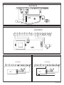
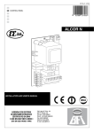
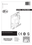
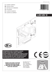
D811509_02 04/06/07
I
QUADRO COMANDO
GB CONTROL PANEL
F
CENTRALE DE COMMANDE
D
STEUERPLATINE
E
CUADRO DE MANDOS
P
QUADRO DE COMANDO
8
027908
297068
ALCOR N
1 2 3 4 5 6 7 8
18 19
15 16 17
12 13 14
9 10 11
ISTRUZIONI D'USO E DI INSTALLAZIONE
INSTALLATION AND USER'S MANUAL
INSTRUCTIONS D'UTILISATION ET D'INSTALLATION
MONTAGE- und BEDIENUNGSANLEITUNG
INSTRUCCIONES DE USO Y DE INSTALACION
INSTRUÇÕES DE USO E DE INSTALAÇÃO
Via Lago di Vico, 44
36015 Schio (VI)
Tel.naz. 0445 696511
Tel.int. +39 0445 696533
Fax 0445 696522
Internet: www.bft.it
E-mail: [email protected]
20
D811509_02
- ALCOR N
D811509_02
ITALIANO
MANUALE D’USO
ENGLISH
USER’S MANUAL
Nel ringraziarVi per la preferenza accordata a questo prodotto, la ditta è certa
che da esso otterrete le prestazioni necessarie al Vostro uso.
Leggete attentamente l’opuscolo “Avvertenze” ed il “Libretto istruzioni” che
accompagnano questo prodotto in quanto forniscono importanti indicazioni
riguardanti la sicurezza, l’installazione, l’uso e la manutenzione. Questo prodotto risponde alle norme riconosciute della tecnica e della disposizioni
relative alla sicurezza. Confermiamo che esso è conforme alle seguenti
direttive europee: 89/336/CEE, 73/23/CEE e loro modifiche successive.
Thank you for buying this product, our company is sure that you will be more
than satisfied with the product’s performance. The product is supplied with
a “Warnings” leaflet and an “Instruction booklet”. These should both be
read carefully as they provide important information about safety, installation, operation and maintenance. This product complies with the recognised
technical standards and safety regulations. We declare that it is in conformity
with the following European Directives: 89/336/EEC, 73/23/EEC and subsequent amendments.
1) GENERALITÀ
La centralina Mod. ALCOR N è adatta per cancelli a battente. Può comandare
uno o due operatori.
1) GENERAL OUTLINE
The ALCOR N mod. control units have been designed to control one single
operator.
2) DEMOLIZIONE
Attenzione: Avvalersi esclusivamente di personale qualificato.
L’eliminazione dei materiali va fatta rispettando le norme vigenti. Nel caso di
demolizione, non esistono particolari pericoli o rischi derivanti dal prodotto
stesso. È opportuno, in caso di recupero dei materiali, che vengano separati
per tipologia (parti elettriche - rame - alluminio - plastica - ecc.).
2) SCRAPPING
Warning: This operation should only be carried out by qualified personnel. Materials must be disposed of in conformity with the current regulations.
In case of scrapping, the automation devices do not entail any particular risks
or danger. In case of materials to be recycled, these should be sorted out by
type (electrical components, copper, aluminium, plastic etc.).
3) SMANTELLAMENTO
Attenzione: Avvalersi esclusivamente di personale qualificato.
Nel caso la centralina venga smontata per essere poi rimontata in altro
sito bisogna:
• Togliere l’alimentazione e scollegare tutto l’impianto elettrico.
• Nel caso alcuni componenti non possano essere rimossi o risultino danneggiati, provvedere alla loro sostituzione.
4) AVVERTENZE
• Assicurarsi che sia presente sulla rete di alimentazione dell’automazione,
un interruttore o un magnetotermico onnipolare con distanza di apertura
dei contatti uguale o superiore a 3,5 mm.
• Assicurarsi che sia presente a monte della rete di alimentazione un
interruttore differenziale con soglia da 0.03A.
• Assicurarsi che i dispositivi di sicurezza applicati al cancello siano sempre funzionanti, altrimenti togliere alimentazione, sbloccare il motore e
rivolgersi subito a personale qualificato.
• Non permettere a persone e bambini di sostare nell’area d’azione dell’automazione.
• Non lasciare radiocomandi o altri dispositivi di comando alla portata dei
bambini onde evitare azionamenti involontari dell’automazione.
• L’utilizzatore deve evitare qualsiasi tentativo di intervento o riparazione
dell’automazione e rivolgersi solo a personale qualificato.
Il buon funzionamento dell’attutatore è garantito solo se vengono
rispettati i dati riportati in questo manuale. La ditta non risponde dei
danni causati dall’inosservanza delle norme di installazione e delle
indicazioni riportate in questo manuale.
Le descrizioni e le illustrazioni del presente manuale non sono impegnative. Lasciando inalterate le caratteristiche essenziali del prodotto,
la Ditta si riserva di apportare in qualunque momento le modifiche che
essa ritiene convenienti per migliorare tecnicamente, costruttivamente
e commercialmente il prodotto, senza impegnarsi ad aggiornare la
presente pubblicazione.
3) DISMANTLING
Warning: This operation should only be carried out by qualified personnel. When the control unit is disassembled to be reassembled on another
site, proceed as follows:
• Disconnect the power supply and the entire electrical installation.
• In the case where some of the components cannot be removed or are
damaged, they must be replaced.
4) WARNING
• Make sure that an omnipolar or magnetothermal switch, having a contact
opening distance equal to or greater than 3,5 mm, is fitted to the automation power supply mains.
• Make sure that a differential switch with a 0.03A threshold is fitted before
the power supply mains.
• Make sure that all safety devices installed on the gate are always in working order; otherwise, disconnect the power supply, release the motors
and immediately request assistance from qualified personnel.
• Do not allow persons or children to remain within the automation operation area.
• Keep radio control or other control devices out of children’s reach, in
order to avoid unintentional automation activation.
• The user must avoid any attempt to carry out work or repair on the automation system, and always request the assistance of qualified personnel.
Correct controller operation is only ensured when the data contained
in the present manual are observed. The company is not to be held
responsible for any damage resulting from failure to observe the
installation standards and the instructions contained in the present
manual.
The descriptions and illustrations contained in the present manual are
not binding. The Company reserves the right to make any alterations
deemed appropriate for the technical, manufacturing and commercial
improvement of the product, while leaving the essential product features unchanged, at any time and without undertaking to update the
present publication.
ALCOR N- D811509_02
INSTALLATION MANUAL
Thank you for buying this product, our company is sure that you will be more
than satisfied with its performance.
This product is supplied with an “Instruction Manual” which should be read
carefully as it provides important information about safety, installation, operation and maintenance.
This product complies with recognised technical standards and safety regulations. We declare that it is in conformity with the following European Directives:
89/336/EEC, 73/23/EEC and subsequent amendments.
1) GENERAL SAFETY
WARNING! An incorrect installation or improper use of the product
can cause damage to persons, animals or things.
• The “Warnings” leaflet and “Instruction booklet” supplied with this
product should be read carefully as they provide important information
about safety, installation, use and maintenance.
• Scrap packing materials (plastic, cardboard, polystyrene etc) according
to the provisions set out by current standards. Keep nylon or polystyrene
bags out of children’s reach.
• Keep the instructions together with the technical brochure for future
reference.
• This product was exclusively designed and manufactured for the use
specified in the present documentation. Any other use not specified in
this documentation could damage the product and be dangerous.
• The Company declines all responsibility for any consequences resulting
from improper use of the product, or use which is different from that
expected and specified in the present documentation.
• Do not install the product in explosive atmosphere.
• The construction components of this product must comply with the following
European Directives: 89/336/CEE, 73/23/EEC, 98/37/EEC and subsequent amendments. As for all non-EEC countries, the above-mentioned
standards as well as the current national standards should be respected
in order to achieve a good safety level.
• The Company declines all responsibility for any consequences resulting
from failure to observe Good Technical Practice when constructing closing
structures (door, gates etc.), as well as from any deformation which might
occur during use.
• The installation must comply with the provisions set out by the following
European Directives: 89/336/CEE, 73/23/EEC, 98/37/EEC and subsequent
amendments.
• Disconnect the electrical power supply before carrying out any work on
the installation. Also disconnect any buffer batteries, if fitted.
• Fit an omnipolar or magnetothermal switch on the mains power supply,
having a contact opening distance equal to or greater than 3,5 mm.
• Check that a differential switch with a 0.03A threshold is fitted just before
the power supply mains.
• Check that earthing is carried out correctly: connect all metal parts for
closure (doors, gates etc.) and all system components provided with an
earth terminal.
• Fit all the safety devices (photocells, electric edges etc.) which are needed
to protect the area from any danger caused by squashing, conveying and
shearing.
• Position at least one luminous signal indication device (blinker) where it
can be easily seen, and fix a Warning sign to the structure.
• The Company declines all responsibility with respect to the automation safety
and correct operation when other manufacturers’ components are used.
• Only use original parts for any maintenance or repair operation.
• Do not modify the automation components, unless explicitly authorised
by the company.
• Instruct the product user about the control systems provided and the
manual opening operation in case of emergency.
• Do not allow persons or children to remain in the automation operation area.
• Keep radio control or other control devices out of children’s reach, in
order to avoid unintentional automation activation.
• The user must avoid any attempt to carry out work or repair on the automation system, and always request the assistance of qualified personnel.
• Anything which is not expressly provided for in the present instructions,
is not allowed.
• �����������������������������������������������������������������������
Installation must be carried out using the safety devices and controls
prescribed by the EN 12978 Standard.
2) GENERAL OUTLINE
ALCOR N mod. control unit has been designed to be applied on swing gates.
It can control one or two operators.
3) TECHNICAL DATA
Power supply: ...............................................................230V±10%, 50Hz(*)
Mains insulation/very low voltage: ................................... > 4MΩ , 500V
Working temperature:................................................................ -10 / +55°C
ENGLISH
Dielectric strength:…. .......................mains/low voltage 3750V~ for 1 minut
Maximum motor power...........................................................1 motor 300W
................................................................................2 motors 300W + 300W
Supply to accessories: . ................................. 24V~, (0.2A max absorption)
Incorporated Rolling-Code radio receiver: . ............. Frequency 433.92MHz
Coding: ...............................................Rolling-Code Algorithm to be cloned
No. combinations:........................................................................... 4 milliard
Antenna impedance:............................................................ 50Ohm (RG58)
Max no. radio transmitters to be memorised:............................................ 63
Dimensions: ...............................................................................see figure 1
(* other voltages available on request)
4) TERMINAL BOARD CONNECTIONS (Fig.2)
For the wiring diagram and the cable section, make reference to the operator’s manual.
WARNING – During the wiring and installation operations, refer to the current
standards as well as principles of good technical practice.
Wires powered at different voltages must be physically separated, or suitably
insulated with at least 1 mm extra insulation. The wires must be clamped by
an extra fastener near the terminals, for example by bands.
All the connection cables must be kept at an adequate distance from the
dissipator.
Connect the yellow/green conductor of the power supply cable to the earth terminal.
230V cables must be physically separate from the safety very low voltage circuits.
Keep the mains voltage connections definitely separate from the (24V) very
low voltage connections.
The capacitors inside the control unit must be positioned in such a way
as not to decrease the surface and air distances with respect to the safety
very low voltage.
WARNING! For connection to the mains, use a multipolar cable with a
minimum of 3x1.5mm2 cross section and complying with the previously mentioned regulations. For example, if the cable is out side (in the
open), it has to be at least equal to H07RN-F, but if it is on the inside
(or outside but placed in a plastic cable cannel) it has to be or at least
egual to H05VV-F with section 3x1.5mm2.
1-2 Power supply 230V +/- 10% 50/60 Hz (Neutral wire to terminal 1).
3-4-5 M1 motor connection (terminal 4 common wire, terminals 3-5 motor
and capacitor operation).
1-4 Blinker connection 230V
6-7-8 M2r motor connection (terminal 7 common wire, terminals 6-8 motor
and capacitor operation).
1-7 Electric lock connection 230V mod. EBP.
9-10 Input for START Button (N.O.).
9-11 Input for STOP Button (N.C.). If not used, leave bridged.
9-12 Input for Photocell (N.C.). If not used, leave bridged.
9-13 Input with function selectable from DSW9:
with DSW9 OFF, Input for Opening Limit Switch (N.C.). If not used,
leave bridged.
with DSW9 ON Input for OPEN Button (N.O.).*
9-14 Input with function selectable from DSW9 and DSW10:
with DSW9 OFF, Input for Closing Limit Switch (N.C.). If not used,
leave bridged.
with DSW9 ON and DSW10 OFF, Input for CLOSE Button (N.O.).*
with DSW9 ON and DSW10 ON, Input for PEDESTRIAN Button
(N.O.). The pedestrian command is active from gate fully closed; if the
gate is not closed, the PEDESTRIAN button carries out the START
functions.*
15-16Output 24V for accessory power supply 200mA MAX.
17-18 Output for second radio channel, N.O. contact (24V / 1A max.). If an
external receiver is used, it must be a double-channel receiver.
A dry N.O. contact must be electrically connected to the terminals.
19-20Input for receiver antenna (20 Braid, 19 Signal).
*With operation without limit switches, the motors remain active for the
working time set.
RX Connector for the external receiver board.
5) LED (Fig.3)
The ALCOR N control units are provided with a series of self-diagnosis
LEDs which control all the functions.
POWER:Led for power supply on.
OP: Led for Signal indication of Motors active on Opening / Led for
Radio Programming.
CL: Led for Signal indication of Motors active on Closing.
START: It comes on with the START command.
STOP: goes off when a STOP command is given.
PHOT: photocell - goes off when the photocells are not aligned or in the
presence of obstacles.
ALCOR N- SWO:
SWC:
INSTALLATION MANUAL
Led for signal indication of input 13 status:
led on= input closed, led off= input open.
Led for signal indication of input 14 status:
led on= input closed, led off= input open.
6) DIP-SWITCH SELECTION (Fig.3)
DIP1)TCA [ON] - Automatic closing time TCA.
ON: Activates automatic closing
OFF: Excludes automatic closing
DIP2) FCH [OFF] - Photocells.
ON: Photocells are only active in the closing phase. If the photocells are
obstructed during closing, the gate reverses its movement and carries
out an opening manoeuvre.
OFF: Photocells are active both in the closing and opening phase. If the
photocells are obstructed, the gate stops. When the photocells are
cleared, the gate resumes it opening manoeuvre.
DIP3) BLI -[OFF] Blocks impulses.
ON: START commands are not accepted during the opening phase.
OFF: START commands are accepted during the opening phase.
DIP4) 3P/4P -[OFF] 3 Steps/4 Steps
ON: Enables 3-step logic. A start impulse has the following effects:
door closed:..............................................................................opens
on opening:.................................stops and enters TCA if configured
door open:................................................................................closes
on closing:................................................................................opens
after stopping:...........................................................................opens
OFF: Enables 4-step logic. A start impulse has the following effects:
door closed:..............................................................................opens
on opening:.................................stops and enters TCA if configured
door open:................................................................................closes
on closing:................................stops and does not enter TCA (stop)
after stopping:...........................................................................opens
DIP5) CODE FIX [OFF] – Fixed code.
ON: Activates incorporated receiver in fixed code mode.
OFF: Activates incorporated receiver in rolling-code mode.
DIP6) RADIO LEARN [OFF] - Radio transmitter programming
ON: This enables transmitter storage via radio:
1 – First press the hidden key (P1) and then the normal key (T1, T2,
T3 or T4) of a transmitter already memorised in standard mode by
means of the radio menu.
2 – Within 10s press the hidden key (P1) and the normal key (T1, T2,
T3 or T4) of a transmitter to be memorised.
The receiver exits the programming mode after 10s, other new transmitters can be entered before the end of this time.
This mode does not require access to the control panel.
OFF: This disables transmitter storage via radio. The transmitters can only be
memorised by pressing the SW1 and SW2 keys (see paragraph 10).
DIP7)Lock hold [OFF]
ON: If the motors remain still in a totally open or closed position for over
one hour, they are activated for about 3 seconds in the respective
direction. This operation takes place once every hour.
N.B.: This function has the purpose of compensating any oil volume
decrease in the hydraulic motors, due to a temperature drop during
prolonged pauses, for instance at night, or to internal leaks.
IMPORTANT - When no adequate mechanical backstops are installed, do not use this function. It is also to be absolutely avoided in the
automation of sliding gates.
OFF: Excludes the said function.
DIP8) Ram blow on opening [OFF]
ON: It pushes for approx. 2 seconds in closing direction before opening.
This allows the electric lock to be released more easily (not affected
by limit switches).
OFF: Excludes the ram blow in closing.
IMPORTANT - When no adequate mechanical backstops are installed, do not use this function. It is also to be absolutely avoided in the
automation of sliding gates.
DIP 9) Function Selection for inputs 13-14 Limit Switches / Buttons
ON: Inputs 13 and 14 are set as Control button inputs. Input 13 for OPEN
button, input 14 according to DSW 10 configuration. With this configuration, the motors remain active for the working time set.
OFF: Inputs 13 and 14 are set as Opening and Closing limit switch inputs,
respectively.
DIP 10) Function Selection for control button inputs 13-14*
N.B. Only with DSW 9 ON. With DSW 9 OFF, the DSW 10 position has no effect.
OFF: Input 14 configured as CLOSE input.
ON: Input 14 configured as PEDESTRIAN input.
*If, when the board is activated, the closing limit switch is neither enabled
nor operating, at the time of the first manoeuvre neither the ram blow nor
the pedestrian opening are carried out.
10 - ALCOR N
D811509_02
ENGLISH
7) TRIMMER ADJUSTMENT (Fig.3)
TCA (Dip1 ON).
It is used to set the automatic closing time, after which the gate closes
automatically (adjustable from 0 to 120 sec.).
TW
It is used to set the motor working time, after which the motor stop (adjustable
from 1 to 90 sec.). When using electrical limit switches, increase the motor
stopping time by a few seconds with respect to the leaf closing time.
DELAY M2
Sets the delay time on closing of motor 2 (M2) (adjustable from 1 to 30
sec.)
8) INTEGRATED RECEIVER TECHNICAL SPECIFICATION
Receiver output channels:
- output channel 1, if activated, controls a START command.
- output channel 2, if activated, controls the excitation of the 2nd radio
channel relay for 1s.
Transmitter versions which can be used:
all Rolling Code transmitters compatible with
.
ANTENNA INSTALLATION
Use an antenna tuned to 433MHz.
For Antenna-Receiver connection, use RG8 coaxial cable.
The presence of metallic masses next to the antenna can interfere with radio
reception. In case of insufficient transmitter range, move the antenna to a
more suitable position.
9) PROGRAMMING
Transmitter storage can be carried out in manual mode, or by means of the
universal palmtop programmer which allows you to create installations in
the “collective receivers” mode, as well as manage the complete installation
database using the EEdbase software.
10) MANUAL PROGRAMMING
In the case of standard installations where no advanced functions are required,
it is possible to proceed to manual storage of the transmitters
1)If you wish the transmitter T key to be memorised as Start, press thSW1 button
on the control unit, otherwise if you wish the transmitter key to be memorise
as second radio channel, press the SW2 button on the control unit.
2)When the OP LED blinks, press the transmitter P1 hidden key, and the
OP LED will stay on permanently.
3)Press the key to be memorised on the transmitter, LED OP will start
blinking again.
4)To memorise another transmitter, repeat steps 2) and 3).
5)To exit the storage mode, wait until the LED is switched off completely.
IMPORTANT NOTE: ATTACH THE ADHESIVE KEY LABEL TO THE FIRST
MEMORISED TRANSMITTER (MASTER).
In the case of manual programming, the first transmitter assigns the key
code to the receiver; this code is necessary in order to carry out subsequent
cloning of the radio transmitters.
10.1) CONTROL UNIT MEMORY CANCELLATION
In order to cancel the control unit memory completely, simultaneously press
for 10 seconds the SW1 and SW2 buttons on the control unit (OP LED
blinking). Correct memory cancellation will be indicated by the OP LED
staying on permanently. To exit the storage mode, wait until the LED is
switched off completely.
11) RECEIVER CONFIGURATION
The on-board receiver combines characteristics of utmost safety in copying
variable code (rolling code) coding with the convenience of carrying out
transmitter “cloning” operations thanks to an exclusive system.
Cloning a transmitter means creating a transmitter which can be automatically
included within the list of the transmitters memorised in the receiver, either
as an addition or as a replacement of a particular transmitter.
Cloning by replacement is used to create a new transmitter which takes
the place of the one previously memorised in the receiver; in this way a
specific transmitter can be removed from the memory and will no longer
be usable.
Therefore it will be possible to remotely program a large number of additional
transmitters or, for example, replacement transmitters for those which have
been lost, without making changes directly to the receiver.
When coding safety is not a decisive factor, the on-board receiver allows
you to carry out fixed-code additional cloning which, although abandoning
the variable code, provides a high number of coding combinations, therefore keeping it possible to “copy” any transmitter which has already been
programmed.
D811509_02
INSTALLATION MANUAL
ENGLISH
12) RADIO-TRANSMITTER CLONING (Fig.7)
Rolling-code cloning / Fixed-code cloning
Make reference to the universal palmtop programmer Instructions and the
CLONIX Programming Guide.
12.1) ADVANCED PROGRAMMING: COLLECTIVE RECEIVERS
Make reference to the universal palmtop programmer Instructions and the
CLONIX Programming Guide.
13) ACCESSORIES
SPL(fig.4). Pre-heating optional board. Recommended for temperatures
below -10°C. (In the case of hydraulic motors).
ME (fig.5).
Optional board used to connect a 12V~ electric lock.
SS (Fig.6/6A) Optional board for gate-open warning light.
WARNING: only works if electrical limit switches are used.
With the limit switches connected (configuration DSW 9 OFF) use the
diagram in figure 6.
With the OPEN - CLOSE/PEDESTRIAN buttons (configuration DSW 9
ON) use the diagram in figure 6A.
EBP(fig.2). The EBP electric lock with continuous service can be connected
directly to terminals 1 and 4.
14) SCRAPPING
Warning: This operation should only be carried out by qualified personnel. Materials must be disposed of in conformity with the current regulations.
In case of scrapping, the automation devices do not entail any particular risks
or danger. In case of materials to be recycled, these should be sorted out by
type (electrical components, copper, aluminium, plastic etc.).
15) DISMANTLING
Warning: this operation should only be carried out by qualified personnel. When the control unit is disassembled to be reassembled on another
site, proceed as follows:
• Disconnect the power supply and the entire electrical installation.
• In the case where some of the components cannot be removed or are
damaged, they must be replaced.
The descriptions and illustrations contained in the present manual are
not binding. The Company reserves the right to make any alterations
deemed appropriate for the technical, manufacturing and commercial
improvement of the product, while leaving the essential product features unchanged, at any time and without undertaking to update the
present publication.
ALCOR N- 11
Fig. 2
D811509_02
Fig. 1
N
1
L
2
207
Fo
ri Ø
6
120
3
M1
~
4
5
EBP
236
6
100
M2r
~
194
7
8
Fig. 3
9
NO
START
NC
STOP
NC
PHOT
12
SWO N.C.
OPEN N.O.
13
SWO N.C.
CLOSE/PED N.O.
14
ALCOR N
0V
24V~
10
11
15
16
17
IIo RC 18
ANTENNA
ANTENNE
ANTENNA
ANTENA
ANTENNE
24 - ALCOR N
19
20
D811509_02
Fig. 4
ALCOR N
SPL
Fig. 5
ALCOR N
ME
Fig. 6
Fig. 6A
ALCOR N
SS
ALCOR N
SS
SWC(N.C.)
ALCOR N- 25
ALCOR N
D811509_02
Fig. 7
4
Programmatore palmare universale
Universal palmtop programmer
Programmateur de poche universel
Universellen Palmtop-Programmierer
Programador de bolsillo universal
Programador palmar universal
UNIDA
Contatti
Contacts
Contacts
Kontakte
Contactos
Contatos
UNIFLAT
UNIFLAT
Contatti
Contacts
Contacts
Kontakte
Contactos
Contatos
UNITRC
UNITRC
P1
T1
UNIFLAT
Contatti
Contacts
Contacts
Kontakte
Contactos
Contatos
T1 2
T 3
T 4
T
T2
Led
UNIMITTO
P1
UNITRC
1
Contatti
Contacts
Contacts
Kontakte
Contactos
Contatos
3
26 - ALCOR N
P1
P1
UNIMITTO
P1
P1
2
1
4
3
2
4
D811509_02
ALCOR N- 27