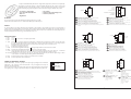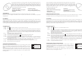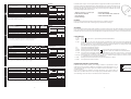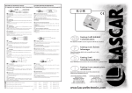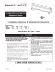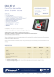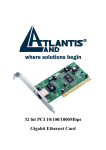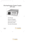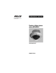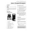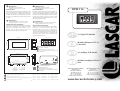
1
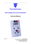
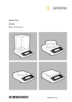
GB
DIMENSIONS
Alle Abmessungen in mm (Zoll)
Einbauausschnitt 45 x 22,2 (1,77 x 0,87)
PANEL FITTING
EINBAUHINWEISE
Fit the bezel to the front of the panel and then locate the
meter into the bezel from behind. Alternatively the
meter and bezel may be assembled before fitting into
the front of the panel but care must be taken not to use
excessive force. Finally fit the window into the front of
the bezel.
F
ABMESSUNGEN
D
All dimensions in mm (inches)
Panel cut-out 45 x 22.2 (1.77 x 0.87)
Bauen Sie die Fassung von vorne in die Frontplatte ein,
und setzen Sie danach das Meßgerät von hinten in die
Fassung ein. Das Meßgerät und die Fassung können auch
vor dem Einbau zusammengebaut werden, dabei muß
jedoch darauf geachtet werden, daß keine Gewalt
angewandt wird. Zu letzt kann das Fenster von vorne in
die Fassung eingesetzt werden.
DIMENSIONS
Tutte le dimensioni sono espresse in mm (pollici)
Finestra pannello 45 x 22,2 (1,77 x 0,87)
INSERTION DANS UN PANNEAU
MONTAGGIO SU PANNELLO
Approchez le cadre par l’avant du panneau et le module
par l’arrière. Alternativement le module et le cadre
peuvent être assemblés avant l’insertion dans le
panneau mais vous devez veiller à ne pas forcer.
Finalement, insérez la glace sur l’avant du cadre.
Montare la cornice sulla parte anteriore del pannello e
posizionare il contatore all’interno della cornice
inserendolo dalla parte posteriore. In alternativa, il
contatore e la cornice possono essere assemblati prima
di essere montati sulla parte anteriore del pannello, ma
in questo caso prestare attenzione a non applicare una
pressione eccessiva. Infine, montare la finestra sulla
parte anteriore della cornice.
a
24 (0.94)
(0.06)
(0.35)
(0.20)
(0.06)
(0.16)
Area di visualizzazione illustrante il display nella
modalità TEST
18.2 (0.72)
9
DP1
DP2
DP3
VTEST
V+
IN HI
IN LO
COM
HOLD
ROH
RHI
1.50
9.00
5.00
1.60
4.00
Sichtfläche mit der Anzeige im Testmodus
I
1
10.4
7.50
2.54
0.50
DP3 DP2 DP1
2
12
e
i
f.
g.
h.
i.
3½-stelliges LCD-Modul
11
4
1
h
a.
b.
c.
d.
e.
Affichage en mode TEST
d
12
g
F
D
c
f
20.4 (0.80)
Module Miniature LCD 3½
Caractères
GB Viewing Area showing display in TEST mode
40.5 (1.59)
38.0 (1.50)
GB
3½ Digit LCD Module
31.0 (1.22)
b
14.0 (0.55)
48 (1.89)
-+
DIMENSIONI
I
Toutes les dimensions sont en mm (pouces)
Découpe panneau 45 x 22,2 (1,77 x 0,87)
DPM 116
1
Modulo con display LCD a 3,5
cifre
GB ON BOARD SOLDER LINKS
(0.41)
(0.30)
(0.10)
(0.02)
F
LIAISONS A SOUDER
D
ZINNBRÜCKEN AUF DER PLATINE
I
COLLEGAMENTI INCORPORATI MEDIANTE
SALDATURA
Specifications liable to change without prior warning
DPM 116
Issue 3
November/1999
M.C.
Applies to DPM 116/2
F
Spécifications peuvent changer sans préavis
DPM 116
Edition 3
novembre/1999
M.C.
Applique à DPM 116/2
D
Die technischen Daten können ohne vorherige Ankündigung geändert werden
DPM 116
Ausgabe 3
November/1999
M.C.
Gilt für DPM 116/2
I
Specifiche soggette a variazione senza preavviso
DPM 116
Versione 3
Novembre/1999
M.C.
Applicabile a DPM 116/2
8
LASCAR ELECTRONICS LIMITED,
MODULE HOUSE,
WHITEPARISH, SALISBURY,
WILTSHIRE SP5 2SJ UK
TEL: +44 (0)1794 884567
FAX: +44 (0)1794 884616
E-MAIL: [email protected]
LASCAR ELECTRONICS, INC.
PO BOX 8204,
SAVANNAH, GA 31412
TEL: +1 (912) 234 2048
FAX: +1 (912) 234 2049
E-MAIL: [email protected]
www.lascarelectronics.com
1
A compact LCD DPM ideally suited to low or high volume applications, it features an exceptionally
large display in a miniature package. The meter will plug directly into a SIL socket or can be panel
mounted using the snap-in bezel provided. The low profile bezel incorporates a flat reverse
printed window giving a superb appearance that cannot be damaged or rubbed off by contact.
• 12.5mm (0.5“) Digit Height
• Logic Selectable Decimal Points
• Auto-zero
• Digital Hold
6
V+
±200mV
• Auto-polarity
• 200mV d.c Full Scale Reading (F.S.R.)
• Low Battery Indication
+
7 IN HI
-
8 IN LO
V5
F
Two resistors may be used to alter the full scale reading of the meter - see table.
Note that the meter will have to be re-calibrated by adjusting the calibration pot .
D
I
SAFETY
7
+
PIN FUNCTIONS
199.9
19.99
Connect to V+ to display required DP.
1.999
Connect to V+ to display segments as illustrated. It should not be operated for more than a few seconds as the
d.c. voltage appliedto the LCD may 'burn' the display. This pin is normally at 5V below V+ and is the ground for
the digital section of the meter. It can be used to power external logic up to a maximum of 1mA.
5. VNegative power supply connection.
6. V+
Positive power supply connection.
7. IN HI Positive measuring differential input.
Analogue inputs must be no closer than 1V to either
8. INLO Negative measuring differential input. the positive or negative supply
9. COM The ground for the analogue section of the A/D converter, held actively at 2.8V (nom.) below V+. COM must
not be allowed to sinkexcessive current (>100µA) by connecting it directly to a higher voltage.
10. HOLD If left floating or connected to TEST (pin 10), the meter will continuously measure the input voltage. When
connected to V+ the last displayed reading will be held indefinitely.
11. RHI
Positive input for reference voltage (connected via Link 1 to ROH).
12. ROH Positive output from internal reference.
D
I
Normally SHORTED
Cut to OPEN
6R2
5K
ZERO
Normally OPEN
Solder to SHORT
IOUT
F
D
I
-
8
F
D
I
V+
V1
IN LO
5
V-
6
V+
IN HI
V2
V-
Measuring 4-20mA to read 0-999. (supply MUST be isolated).
Vérifier que la liaison 2 est OUVRIR
Mesure de 4-20mA pour lire 0-999. (L’alimentation DOIT être isolée).
Prüfen Sie, ob Verbindung 2 OFFEN ist.
Messung von 4 - 20 mA bei Anzeige 0 - 999.
(Versorgung muß elektrisch getrennt sein.)
Verificare che il collegamento 2 sia APERTO.
Misurazione di 4-20mA per leggere 0-999.
(l’alimentazione DEVE essere isolata).
14V max
7V min
IN LO
V5
V-
Split supply operation.
Vérifier que la liaison 2 est OUVRIR
Utilisation en alimentation séparées.
Prüfen Sie, ob Verbindung 2 OFFEN ist.
Betrieb mit aufgespaltener Stromversorgung.
Verificare che il collegamento 2 sia APERTO.
Funzionamento mediante alimentazione separata.
V+
IN HI
V5
GB Check Link 2 is OPEN.
9 COM
V-
GB Check Link 2 is OPEN.
2
8
SET
6
+
7
0V
1V
min.
Measuring current. Supply MUST be isolated.
Vérifier que la liaison 2 est FERMER
Mesure de courant. L’alimentation DOIT être isolée.
Prüfen Sie, ob Verbindung 2 KURZGESCHLOSSEN ist.
Strommessung. Versorgung muß elektrisch getrennt sein.
Verificare che il collegamento 2 sia CORTOCIRCUITATO.
Misurazione della corrente. L’alimentazione DEVE essere isolata.
7
IN LO
510K
Check Link 2 is OPEN.
Measuring a supply voltage. (min. 7.5V, max. 14V).
Vérifier que la liaison 2 est OUVRIR
Mesure d’une tension d’alimentation. (min. 7,5V - max. 14V).
Prüfen Sie, ob Verbindung 2 OFFEN ist.
Messung einer Versorgungsspannung. (min. 7,5 V, max. 14 V)
Verificare che il collegamento 2 sia APERTO.
Misurazione di una tensione di alimentazione (min. 7,5V, max. 14V).
±200mV
GB Check Links 2 is SHORTED.
F
IN HI
V+
V+
6
V+
IN HI
100K
ON-BOARD LINKS: In order to quickly and easily change operating modes for different
applications, the meter has several on-board links. They are designed to be easily cut
(opened) or shorted (soldered).
Do not connect more than one meter to the same power supply if the meters cannot use the
same signal ground. Taking any input beyond the power supply rails will damage the meter.
I
8 IN LO
VR=0.2
5 VIF.S.R.
-
IIN
VARIOUS OPERATING MODES
F
D
R-
DP1
DP2
DP3
TEST
8
TENSIONE
D'INGRESSO
GB
V+
10K
VERSORGUNGSSPANNUNG
Measuring a floating voltage source of 200mV full scale.
Vérifier que la liaison 2 est FERMER
Mesure d’un voltage flottant de 200mV pleine échelle.
Prüfen Sie, ob Verbindung 2 KURZGESCHLOSSEN ist.
Messung einer potentialfreien Spannung mit 200 mV Vollausschlag.
Verificare che il collegamento 2 sia CORTOCIRCUITATO.
Misurazione di una sorgente di tensione oscillante di 200mV in grandezza
naturale.
To comply with the Low Voltage Directive (LVD 93/68/EEC), input voltages to the module’s pins must not exceed 60Vdc. If
voltages to the measuring inputs do exceed 60Vdc, then fit scaling resistors externally to the module. The user must ensure that
the incorporation of the DPM into the user’s equipment conforms to the relevant sections of BS EN 61010 (Safety Requirements
for Electrical Equipment for Measuring, Control and Laboratory Use).
7
TENSION
D’ALIMENTATION
V-
6
V+
510K
SUPPLY
VOLTAGE
GB Check Links 2 is SHORTED.
SCALING
1.
2.
3.
4.
V+
GB Check Links 1 & 4 are OPEN.
F
7
6
V+
+ 7 IN HI
8
IN LO
+ 11 REF HI
- 10 REF LO
V5
Measuring the ratio of two voltages.
Reading = 1000 V1/V2
50mV< V2<200mV
V1<2V2
Vérifier que les liaisons 1 & 4
sont OUVERTES.
Mesure du ratio de deux voltages
Lecture = 1000V1/V2
50mV<V2<200mV
V1<2V2
D
I
V+
V-
Überprüfen Sie, daß Brücke 1 u. 4
OFFEN sind.
Messung eines
Spannungsverhältnisses.
Meßwert = 1000 V1/V2
50 mV < V2 < 200 mV
V1 < 2 V2
Controllare che i collegamenti
1 e 4 siano APERTI.
Misurazione del rapporto delle
due tensioni.
Lettura = 1000 V1/V2
50mV <V2 <200mV
V1,2V2
GB
Specification
Accuracy (overall error) *
Linearity
Sample rate
Operating temperature range
Temperature stability
Supply voltage (V+ to V-)
Supply current
Input leakage current (Vin = 0V)
Min.
Typ.
Max.
Unit
0.05
0.1
±1
%(±1 count)
count
samples/sec
°C
ppm/°C
V
µA
pA
3
0
50
100
9
150
1
7.5
14
10
* To ensure maximum accuracy, re-calibrate periodically.
** Ensure Ra is rated for high voltage use.
F
Caractéristiques
Précision (erreur globale) *
Linéarité
Taux d’échantillonnage
Températures limites d’utilisation
Stabilité thermique
Voltage d’alimentation (de V+ à V-)
Courant d’alimentation
Courant d’entrée de fuite (Vin = 0V)
Min.
Typ.
Max.
Unité
0,05
0,1
±1
%(±1 compte)
compte
éch./sec
°C
ppm/°C
V
µA
pA
3
0
7,5
50
100
9
150
1
14
10
* Pour obtenir une précision maximum, recalibrez périodiquement.
** Assurez-vous que Ra peut supporter des voltages importants.
D
Parameter
Genauigkeit (Gesamtfehler) *
Linearität
Abtastrate
Betriebs-temperatur-bereich
Temperatur-stabilität
Versorgungs-spannung (V+ bis V-)
Versorgungsstrom
Kriechstrom am Eingang (Vein = 0V)
Min. Typisch Max.
Einheit
0,05
%(±1 Zählwert)
Zählwert
Proben/sek.
°C
ppm/°C
V
µA
pA
0,1
±1
3
0
7,5
50
100
9
150
1
14
10
* Um maximale Genauigkeit zu gewährleisten, periodisch kalibrieren.
** Sorgen Sie dafür, daß Ra auf hohe Spannungen ausgelegt ist.
I
Specifica
Precisione (errore complessivo) *
Linearità
Frequenza di campionamento
Gamma temperatura di esercizio
Stabilità temperatura
Tensione di alimentazione (da V+ a V-)
Corrente di alimentazione
Corrente di perdita in entrata (Vin = 0V)
Min.
Tip.
Max.
Unitá
0,05
0,1
±1
%(± 1 conteggio)
conteggio
campioni /sec.
°C
ppm/°C
V
µA
pA
3
0
7,5
50
100
9
150
1
14
10
* Per garantire la massima precisione, rieffettuare periodicamente la taratura.
** Assicurarsi che Ra sia regolato per impiego ad alta tensione.
6
SCALING
+
Ra
IN HI (7)
Rb
INPUT
IN LO (8)
Required F.S.R.
2V
20V
200V
2kV **
200µA
2mA
20mA
200mA
Ra
Rb
910k
1M
1M
1M
0R
0R
0R
0R
100k
10k
1k
100R
1k
100R
10R
1R
Ce DPM LCD est compact et convient parfaitement aux applications à faible ou à grand volume de
production. Il offre un grand afficheur dans un boîtier miniature. Il se connecte directement sur un
support SIL ou peut être monté sur un panneau en encliquetant le cadre fourni. Le cadre à profil
bas intègre une glace plate imprimée au dos qui procure une apparence esthétique qui ne peut
être ni endommagée ni effacée par contact.
• Taille des Caractères : 12,5 mm (0,5")
• Point Décimal Contrôlable
• Zéro Automatique
• Gèle de l’Affichage
• Polarité Automatique
• Lecture Pleine Echelle (L.P.E) : 200mV d.c.
• Témoin de Batterie Faible
ECHELLE
Deux résistances peuvent être ajoutées pour changer la L.P.E. (cf. tableau ci dessous).
Notez que l’instrument devra être re-calibré grâce au potentiomètre de calibrage.
ECHELLE
+
Ra
ENTREE
IN HI (7)
Rb
IN LO (8)
L.P.E. Désirée
2V
20V
200V
2kV **
200µA
2mA
20mA
200mA
Ra
Ra
100k
10k
1k
100R
1k
100R
10R
1R
EIN HI (7)
Rb
EINGANG
-
EIN LO (8)
Erforderlicher Endausschlag
Ra
Rb
2V
20V
200V
2kV **
200µA
2mA
20mA
200mA
910k
1M
1M
1M
0R
0R
0R
0R
100k
10k
1k
100R
1k
100R
10R
1R
DIMENSIONAMENTO IN SCALA
+
Ra
ENTRATA
IN HI (7)
Rb
IN LO (8)
F.S.R Richiesto
2V
20V
200V
2kV **
200µA
2mA
20mA
200mA
Ra
910k
1M
1M
1M
0R
0R
0R
0R
Pour respecter le Directif Bas Voltage (LVD 93/68/EEC), les voltages d’entrées sur les broches du module ne doivent pas dépasser
60Vcc. Si les voltages sur les broches de mesure dépassent 60Vcc, il faut monter les résistances d’echelle à l’externe du module.
L’utilisateur doit s’asseur que l’incorporation du DPM dans son équipement respecte les sections concernées de l’IEC 1010.
Rb
910k
1M
1M
1M
0R
0R
0R
0R
MESSBEREICH
+
SECURITE
CONNEXIONS
1.
2.
3.
4.
DP1
DP2
DP3
TEST
199.9
19.99
A connecter à V+ pour afficher le point décimal (DP) désiré.
1.999
A connecter à V+ pour activer tous les segments comme illustré. La tension ne doit pas être appliquée plus que
quelques secondes pour ne pas endommager l’afficheur. La tension de cette broche est normalement inférieure
de 5V par rapport à V+ et est aussi la masse pour la partie digitale du voltmètre. Ce contact peut aussi être utilisé
pour alimenter un circuit logique externe dans la limite de 1mA.
5. VConnexion de l’alimentation négative.
6. V+
Connexion de l’alimentation positive.
7. IN HI Entrée positive de mesure différentielle.
Les tensions des entrées analogiques ne doivent pas
8. IN LO Entrée négative de mesure différentielle.
s’approcher à moins d’un volt des tensions D’alimentation.
9. COM Terre de la section analogique de l’ADC, elle est maintenue à 2,8V (nom.) en dessous de V+ et ne doit pas être
traversée par un courant de fuite excessif (>100µA), en la connectant, par exemple, à une tension supérieure.
10. HOLD Si laissée flottante ou connectée à TEST (broche 10), le voltmètre mesurera l’entrée en continu. Si connectée à
V+ la dernière lecture sera maintenue indéfiniment.
11. RHI
Entrée positive de la tension référence (Connectée via la liaison 1 à ROH).
12. ROH
Sortie positive de la référence interne.
EXEMPLE DE MODES D’UTILISATION
LIAISONS SITUEES SUR LA CARTE : Pour changer facilement et rapidement de mode
d’utilisation pour des applications différentes, le voltmètre possède plusieurs liaisons sur la
carte imprimée. Elles sont conçues pour être facilement ouvertes (désoudées) ou courtcircuitées (soudées).
Ne pas connecter plus d’un voltmètre à la même alimentation s'ils ne peuvent utiliser la
même masse. Le filtre d’entrée doit se trouver le plus près possible du voltmètre. Ce dernier
sera endommagé si l’une des entrées va au-delà des tensions d’alimentation.
Rb
100k
10k
1k
100R
1k
100R
10R
1R
3
Normalement FERMEE
Couper pour OUVRIR
Normalement OUVERTE
Souder pour FERMER
Ein kompaktes LCD-DPM, das sich ideal für Klein- und Großserien eignet und gemessen an
seinem kleinen Format eine außerordentlich große Anzeige aufweist. Dieses Gerät läßt sich
einfach in einen SIL-Sockel stecken oder mit dem mitgelieferten Einrastrahmen direkt in ein
Gehäuse einbauen. Der Niederprofilrahmen beinhaltet ein flaches Fenster mit Druckbild von
hinten. Diese Darstellungsweise bietet ein hervorragendes Erscheinungsbild, das durch Kontakt
weder beschädigt noch abgerieben werden kann.
Apparecchio DPM LCD compatto particolarmente indicato per applicazioni a bassi o alti volumi.
Questo modulo è dotato di un display estremamente ampio contenuto in una custodia in formato
miniatura. Il misuratore può essere inserito direttamente in una presa single in line oppure
montato a pannello mediante la cornice a scatto fornita. La cornice a basso profilo racchiude
un'elegante finestra piatta con stampa sul retro, che ne impedisce il danneggiamento o la
cancellazione per effetto del contatto.
• Ziffernhöhe 12,5 mm (0,5")
• Durch die Logik wählbarer Dezimalpunkt
• Automatische Nullstellung
• Digitalhalt
• Altezza cifre 12,5 mm (0,5")
• Punti decimali selezionabili mediante logica
• Automatische Polarität
• 200 mV= Vollausschlag (F.S.R.)
• Anzeige für niedrige Batteriespannung
MESSBEREICH
Der Wert für den Vollausschlag des Meßgeräts kann durch zwei Widerstände geändert werden – siehe Tabelle.
Beachten Sie, daß das Meßgerät neu kalibriert werden muß, indem das Potentiometer zum Kalibrieren entsprechend
nachgestellt wird.
SICHERHEIT
• Autoazzeramento
• Mantenimento del display
• Autopolarità
• Lettura valori in grandezza naturale
(F.S.R.) 200 mV c.c.
• Segnalazione batteria in esaurimento
DIMENSIONAMENTO IN SCALA
Per modificare la lettura dei valori in grandezza naturale del contatore, possono essere utilizzati due resistori – ved. tavola.
Va sottolineato che sarà necessario rieseguire la taratura del contatore regolando il potenziometro di taratura.
SICUREZZA
Damit den Niederspannungsvorschriften (LVD 93/68/EEC) entsprochen wird, dürfen die Spannungen, die an die Kontakte des
Moduls angeschlossen werden, nicht über 60 V= liegen. Sollte es erforderlich sein, eine Spannung über 60 V= an die
Meßgeräteeingänge anzulegen, dann muß an das Modul ein externer Spannungsteiler angeschlossen werden. Außerdem muß
der Benutzer dafür sorgen, daß der Einbau des DPM in die Geräte des Anwenders den zutreffenden Abschnitten von BS EN
61010 entspricht (Sicherheitsbestimmungen für elektrische Geräte zum Einsatz für Meßzwecke, Steuerung und im Labor).
Per essere conformi alla Direttiva sulla bassa tensione (LVD 93/68/EEC), le tensioni in entrata ai pin del modulo non devono
essere superiori a 60V c.c. Nel caso in cui le tensioni alle entrate di misurazione oltrepassino 60V c.c., montare i resistori di
dimensionamento in scala all’esterno del modulo. L’utente deve assicurasi che l’integrazione del DPM nell’apparecchiatura
dell’utente sia conforme alle sezioni pertinenti della normativa BS EN 61010 (Requisiti di sicurezza relativi alle apparecchiature
elettriche per la misurazione, il controllo e l’uso in laboratorio).
STIFTBELEGUNG
FUNZIONI DEI PIN
1.
2.
3.
4.
DP1
DP2
DP3
TEST
199.9
19.99
An Pluspol anschließen, um gewünschten DP anzuzeigen.
1.999
An V+ anschließen, um die Segmente wie dargestellt anzuzeigen. Die Spannung sollte jedoch nicht länger als
einige Sekunden angelegt werden, da die Anzeige durch die Gleichspannung eingebrannt werden kann.
Dieser Stift liegt normalerweise auf 5 V unter V+ und ist der Masseanschluß für den Digitalteil des Meßgerätes.
Dieser Kontakt kann auch zur Versorgung einer externen Schaltung verwendet werden, und zwar maximal
1mA.
5. VAnschluß für die negative Spannungsversorgung.
6. V+
Anschluß für die positive Spannungsversorgung.
7. IN HI Positiver Differenzialeingang Meßwert.
Analoge Eingangsspannung dürfen weder
8. INLO Negativer Differenzialeingang Meßwert.
an plus noch an minus über 1 V liegen.
9. COM Die Masse für den Analogteil des A/D-Wandlers; liegt bei 2,8 V (nominal) unter V+. Es ist nicht zulässig, daß
der Masseanschluß einen übermäßigen Strom aufnimmt (> 100 µA), indem der Anschluß an eine höhere
Spannung angeschlossen wird.
10. HOLD Im fließenden Zustand oder bei Anschluß an TEST (PIN 10) mißt dieses Gerät ununterbrochen die
Eingangsspannung. Bei Anschluß an V+ wird die letzte Messung unbeschränkt gehalten.
11. RHI
Pluspol Eingang für die Referenzspannung (kann über die Brücke 1 an R OH angeschlossen werden).
12. ROH Pluspol Ausgang von der internen Referenz.
1.
2.
3.
4.
DP1
DP2
DP3
TEST
5.
6.
7.
8.
9.
VV+
IN HI
INLO
COM
10. HOLD
11. RHI
12. ROH
199.9
Collegare a V + per visualizzare il DP necessario.
19.99
1.999
Collegare a V + per visualizzare i segmenti come illustrato. Non deve essere messo in funzione per più di alcuni
secondi, poiché la tensione c.c. applicata al display LCD può “bruciare” il display. Questo pin si trova
normalmente a 5V al di sotto di V + e rappresenta la massa per la sezione digitale del contatore. Può essere
utilizzato per alimentare la logica esterna fino ad un massimo di 1 mA.
Collegamento alimentazione negativa.
Collegamento alimentazione positiva.
Entrata positiva differenziale di misurazione.
Le entrate analogiche non devono essere di oltre 1V sia
Entrata negativa differenziale di misurazione. rispetto all’alimentazione positiva che a quella negativa.
Massa per la sezione analogica del convertitore analogico-digitale, mantenuta attivamente a 2,8V (nom.) al di
sotto di V+. Non deve essere consentito a COM di disperdere una corrente eccessiva (> 100µA) collegandolo
direttamente ad una tensione superiore.
Se viene lasciato fluttuante o collegato a TEST (pin 10), il misuratore rileverà continuamente la tensione
d'ingresso. Se collegato a V+, l'ultima lettura visualizzata verrà mantenuta per un tempo indeterminato.
Entrata positiva per tensione di riferimento (collegata tramite il collegamento 1 a ROH).
Uscita positiva dal riferimento interno.
VARIE MODALITÀ DI FUNZIONAMENTO
VERSCHIEDENE BETRIEBSARTEN
BRÜCKEN AUF DER PLATINE: Damit die Betriebsart rasch und einfach geändert werden
kann, ist das Meßgerät mit einigen Brücken auf der Platine ausgestattet. Sie sind so
konzipiert, daß sie einfach durchgetrennt (geöffnet) oder kurzgeschlossen (verlötet) werden
können.
Mehrere Meßgeräte dürfen nicht an die gleiche Stromversorgung angeschlossen werden,
wenn nicht die gleiche Signalmasse verwendet werden kann. Sollte die Spannung an
irgendeinem Eingang über der Versorgungsspannung liegen, kann das Meßgerät dadurch
beschädigt werden.
4
Normalerweise
KURZGESCHLOSSEN
Zum ÖFFNEN durchtrennen
Normalerweise OFFEN Zum
KURZSCHLIESSEN zulöten
COLLEGAMENTI INCORPORATI: Al fine di modificare in modo rapido e semplice le
modalità di funzionamento per le varie applicazioni, il contatore è dotato di numerosi
collegamenti incorporati, che sono stati progettati in modo da essere facilmente interrotti
(aperti) o chiusi (saldati).
Non collegare più di un contatore alla stessa alimentazione, se i contatori non possono
utilizzare la stessa massa del segnale. Non utilizzare nessuna entrata oltre le rotaie
dell’alimentazione per non danneggiare il contatore.
5
Normalmente CHIUSO
Interrompere per APRIRE
Normalmente APERTO
Saldare per CHIUDERE
GB
Specification
Accuracy (overall error) *
Linearity
Sample rate
Operating temperature range
Temperature stability
Supply voltage (V+ to V-)
Supply current
Input leakage current (Vin = 0V)
Min.
Typ.
Max.
Unit
0.05
0.1
±1
%(±1 count)
count
samples/sec
°C
ppm/°C
V
µA
pA
3
0
50
100
9
150
1
7.5
14
10
* To ensure maximum accuracy, re-calibrate periodically.
** Ensure Ra is rated for high voltage use.
F
Caractéristiques
Précision (erreur globale) *
Linéarité
Taux d’échantillonnage
Températures limites d’utilisation
Stabilité thermique
Voltage d’alimentation (de V+ à V-)
Courant d’alimentation
Courant d’entrée de fuite (Vin = 0V)
Min.
Typ.
Max.
Unité
0,05
0,1
±1
%(±1 compte)
compte
éch./sec
°C
ppm/°C
V
µA
pA
3
0
7,5
50
100
9
150
1
14
10
* Pour obtenir une précision maximum, recalibrez périodiquement.
** Assurez-vous que Ra peut supporter des voltages importants.
D
Parameter
Genauigkeit (Gesamtfehler) *
Linearität
Abtastrate
Betriebs-temperatur-bereich
Temperatur-stabilität
Versorgungs-spannung (V+ bis V-)
Versorgungsstrom
Kriechstrom am Eingang (Vein = 0V)
Min. Typisch Max.
Einheit
0,05
%(±1 Zählwert)
Zählwert
Proben/sek.
°C
ppm/°C
V
µA
pA
0,1
±1
3
0
7,5
50
100
9
150
1
14
10
* Um maximale Genauigkeit zu gewährleisten, periodisch kalibrieren.
** Sorgen Sie dafür, daß Ra auf hohe Spannungen ausgelegt ist.
I
Specifica
Precisione (errore complessivo) *
Linearità
Frequenza di campionamento
Gamma temperatura di esercizio
Stabilità temperatura
Tensione di alimentazione (da V+ a V-)
Corrente di alimentazione
Corrente di perdita in entrata (Vin = 0V)
Min.
Tip.
Max.
Unitá
0,05
0,1
±1
%(± 1 conteggio)
conteggio
campioni /sec.
°C
ppm/°C
V
µA
pA
3
0
7,5
50
100
9
150
1
14
10
* Per garantire la massima precisione, rieffettuare periodicamente la taratura.
** Assicurarsi che Ra sia regolato per impiego ad alta tensione.
6
SCALING
+
Ra
IN HI (7)
Rb
INPUT
IN LO (8)
Required F.S.R.
2V
20V
200V
2kV **
200µA
2mA
20mA
200mA
Ra
Rb
910k
1M
1M
1M
0R
0R
0R
0R
100k
10k
1k
100R
1k
100R
10R
1R
Ce DPM LCD est compact et convient parfaitement aux applications à faible ou à grand volume de
production. Il offre un grand afficheur dans un boîtier miniature. Il se connecte directement sur un
support SIL ou peut être monté sur un panneau en encliquetant le cadre fourni. Le cadre à profil
bas intègre une glace plate imprimée au dos qui procure une apparence esthétique qui ne peut
être ni endommagée ni effacée par contact.
• Taille des Caractères : 12,5 mm (0,5")
• Point Décimal Contrôlable
• Zéro Automatique
• Gèle de l’Affichage
• Polarité Automatique
• Lecture Pleine Echelle (L.P.E) : 200mV d.c.
• Témoin de Batterie Faible
ECHELLE
Deux résistances peuvent être ajoutées pour changer la L.P.E. (cf. tableau ci dessous).
Notez que l’instrument devra être re-calibré grâce au potentiomètre de calibrage.
ECHELLE
+
Ra
ENTREE
IN HI (7)
Rb
IN LO (8)
L.P.E. Désirée
2V
20V
200V
2kV **
200µA
2mA
20mA
200mA
Ra
Ra
100k
10k
1k
100R
1k
100R
10R
1R
EIN HI (7)
Rb
EINGANG
-
EIN LO (8)
Erforderlicher Endausschlag
Ra
Rb
2V
20V
200V
2kV **
200µA
2mA
20mA
200mA
910k
1M
1M
1M
0R
0R
0R
0R
100k
10k
1k
100R
1k
100R
10R
1R
DIMENSIONAMENTO IN SCALA
+
Ra
ENTRATA
IN HI (7)
Rb
IN LO (8)
F.S.R Richiesto
2V
20V
200V
2kV **
200µA
2mA
20mA
200mA
Ra
910k
1M
1M
1M
0R
0R
0R
0R
Pour respecter le Directif Bas Voltage (LVD 93/68/EEC), les voltages d’entrées sur les broches du module ne doivent pas dépasser
60Vcc. Si les voltages sur les broches de mesure dépassent 60Vcc, il faut monter les résistances d’echelle à l’externe du module.
L’utilisateur doit s’asseur que l’incorporation du DPM dans son équipement respecte les sections concernées de l’IEC 1010.
Rb
910k
1M
1M
1M
0R
0R
0R
0R
MESSBEREICH
+
SECURITE
CONNEXIONS
1.
2.
3.
4.
DP1
DP2
DP3
TEST
199.9
19.99
A connecter à V+ pour afficher le point décimal (DP) désiré.
1.999
A connecter à V+ pour activer tous les segments comme illustré. La tension ne doit pas être appliquée plus que
quelques secondes pour ne pas endommager l’afficheur. La tension de cette broche est normalement inférieure
de 5V par rapport à V+ et est aussi la masse pour la partie digitale du voltmètre. Ce contact peut aussi être utilisé
pour alimenter un circuit logique externe dans la limite de 1mA.
5. VConnexion de l’alimentation négative.
6. V+
Connexion de l’alimentation positive.
7. IN HI Entrée positive de mesure différentielle.
Les tensions des entrées analogiques ne doivent pas
8. IN LO Entrée négative de mesure différentielle.
s’approcher à moins d’un volt des tensions D’alimentation.
9. COM Terre de la section analogique de l’ADC, elle est maintenue à 2,8V (nom.) en dessous de V+ et ne doit pas être
traversée par un courant de fuite excessif (>100µA), en la connectant, par exemple, à une tension supérieure.
10. HOLD Si laissée flottante ou connectée à TEST (broche 10), le voltmètre mesurera l’entrée en continu. Si connectée à
V+ la dernière lecture sera maintenue indéfiniment.
11. RHI
Entrée positive de la tension référence (Connectée via la liaison 1 à ROH).
12. ROH
Sortie positive de la référence interne.
EXEMPLE DE MODES D’UTILISATION
LIAISONS SITUEES SUR LA CARTE : Pour changer facilement et rapidement de mode
d’utilisation pour des applications différentes, le voltmètre possède plusieurs liaisons sur la
carte imprimée. Elles sont conçues pour être facilement ouvertes (désoudées) ou courtcircuitées (soudées).
Ne pas connecter plus d’un voltmètre à la même alimentation s'ils ne peuvent utiliser la
même masse. Le filtre d’entrée doit se trouver le plus près possible du voltmètre. Ce dernier
sera endommagé si l’une des entrées va au-delà des tensions d’alimentation.
Rb
100k
10k
1k
100R
1k
100R
10R
1R
3
Normalement FERMEE
Couper pour OUVRIR
Normalement OUVERTE
Souder pour FERMER
A compact LCD DPM ideally suited to low or high volume applications, it features an exceptionally
large display in a miniature package. The meter will plug directly into a SIL socket or can be panel
mounted using the snap-in bezel provided. The low profile bezel incorporates a flat reverse
printed window giving a superb appearance that cannot be damaged or rubbed off by contact.
• 12.5mm (0.5“) Digit Height
• Logic Selectable Decimal Points
• Auto-zero
• Digital Hold
6
V+
±200mV
• Auto-polarity
• 200mV d.c Full Scale Reading (F.S.R.)
• Low Battery Indication
+
7 IN HI
-
8 IN LO
V5
F
Two resistors may be used to alter the full scale reading of the meter - see table.
Note that the meter will have to be re-calibrated by adjusting the calibration pot .
D
I
SAFETY
7
+
PIN FUNCTIONS
199.9
19.99
Connect to V+ to display required DP.
1.999
Connect to V+ to display segments as illustrated. It should not be operated for more than a few seconds as the
d.c. voltage appliedto the LCD may 'burn' the display. This pin is normally at 5V below V+ and is the ground for
the digital section of the meter. It can be used to power external logic up to a maximum of 1mA.
5. VNegative power supply connection.
6. V+
Positive power supply connection.
7. IN HI Positive measuring differential input.
Analogue inputs must be no closer than 1V to either
8. INLO Negative measuring differential input. the positive or negative supply
9. COM The ground for the analogue section of the A/D converter, held actively at 2.8V (nom.) below V+. COM must
not be allowed to sinkexcessive current (>100µA) by connecting it directly to a higher voltage.
10. HOLD If left floating or connected to TEST (pin 10), the meter will continuously measure the input voltage. When
connected to V+ the last displayed reading will be held indefinitely.
11. RHI
Positive input for reference voltage (connected via Link 1 to ROH).
12. ROH Positive output from internal reference.
D
I
Normally SHORTED
Cut to OPEN
6R2
5K
ZERO
Normally OPEN
Solder to SHORT
IOUT
F
D
I
-
8
F
D
I
V+
V1
IN LO
5
V-
6
V+
IN HI
V2
V-
Measuring 4-20mA to read 0-999. (supply MUST be isolated).
Vérifier que la liaison 2 est OUVRIR
Mesure de 4-20mA pour lire 0-999. (L’alimentation DOIT être isolée).
Prüfen Sie, ob Verbindung 2 OFFEN ist.
Messung von 4 - 20 mA bei Anzeige 0 - 999.
(Versorgung muß elektrisch getrennt sein.)
Verificare che il collegamento 2 sia APERTO.
Misurazione di 4-20mA per leggere 0-999.
(l’alimentazione DEVE essere isolata).
14V max
7V min
IN LO
V5
V-
Split supply operation.
Vérifier que la liaison 2 est OUVRIR
Utilisation en alimentation séparées.
Prüfen Sie, ob Verbindung 2 OFFEN ist.
Betrieb mit aufgespaltener Stromversorgung.
Verificare che il collegamento 2 sia APERTO.
Funzionamento mediante alimentazione separata.
V+
IN HI
V5
GB Check Link 2 is OPEN.
9 COM
V-
GB Check Link 2 is OPEN.
2
8
SET
6
+
7
0V
1V
min.
Measuring current. Supply MUST be isolated.
Vérifier que la liaison 2 est FERMER
Mesure de courant. L’alimentation DOIT être isolée.
Prüfen Sie, ob Verbindung 2 KURZGESCHLOSSEN ist.
Strommessung. Versorgung muß elektrisch getrennt sein.
Verificare che il collegamento 2 sia CORTOCIRCUITATO.
Misurazione della corrente. L’alimentazione DEVE essere isolata.
7
IN LO
510K
Check Link 2 is OPEN.
Measuring a supply voltage. (min. 7.5V, max. 14V).
Vérifier que la liaison 2 est OUVRIR
Mesure d’une tension d’alimentation. (min. 7,5V - max. 14V).
Prüfen Sie, ob Verbindung 2 OFFEN ist.
Messung einer Versorgungsspannung. (min. 7,5 V, max. 14 V)
Verificare che il collegamento 2 sia APERTO.
Misurazione di una tensione di alimentazione (min. 7,5V, max. 14V).
±200mV
GB Check Links 2 is SHORTED.
F
IN HI
V+
V+
6
V+
IN HI
100K
ON-BOARD LINKS: In order to quickly and easily change operating modes for different
applications, the meter has several on-board links. They are designed to be easily cut
(opened) or shorted (soldered).
Do not connect more than one meter to the same power supply if the meters cannot use the
same signal ground. Taking any input beyond the power supply rails will damage the meter.
I
8 IN LO
VR=0.2
5 VIF.S.R.
-
IIN
VARIOUS OPERATING MODES
F
D
R-
DP1
DP2
DP3
TEST
8
TENSIONE
D'INGRESSO
GB
V+
10K
VERSORGUNGSSPANNUNG
Measuring a floating voltage source of 200mV full scale.
Vérifier que la liaison 2 est FERMER
Mesure d’un voltage flottant de 200mV pleine échelle.
Prüfen Sie, ob Verbindung 2 KURZGESCHLOSSEN ist.
Messung einer potentialfreien Spannung mit 200 mV Vollausschlag.
Verificare che il collegamento 2 sia CORTOCIRCUITATO.
Misurazione di una sorgente di tensione oscillante di 200mV in grandezza
naturale.
To comply with the Low Voltage Directive (LVD 93/68/EEC), input voltages to the module’s pins must not exceed 60Vdc. If
voltages to the measuring inputs do exceed 60Vdc, then fit scaling resistors externally to the module. The user must ensure that
the incorporation of the DPM into the user’s equipment conforms to the relevant sections of BS EN 61010 (Safety Requirements
for Electrical Equipment for Measuring, Control and Laboratory Use).
7
TENSION
D’ALIMENTATION
V-
6
V+
510K
SUPPLY
VOLTAGE
GB Check Links 2 is SHORTED.
SCALING
1.
2.
3.
4.
V+
GB Check Links 1 & 4 are OPEN.
F
7
6
V+
+ 7 IN HI
8
IN LO
+ 11 REF HI
- 10 REF LO
V5
Measuring the ratio of two voltages.
Reading = 1000 V1/V2
50mV< V2<200mV
V1<2V2
Vérifier que les liaisons 1 & 4
sont OUVERTES.
Mesure du ratio de deux voltages
Lecture = 1000V1/V2
50mV<V2<200mV
V1<2V2
D
I
V+
V-
Überprüfen Sie, daß Brücke 1 u. 4
OFFEN sind.
Messung eines
Spannungsverhältnisses.
Meßwert = 1000 V1/V2
50 mV < V2 < 200 mV
V1 < 2 V2
Controllare che i collegamenti
1 e 4 siano APERTI.
Misurazione del rapporto delle
due tensioni.
Lettura = 1000 V1/V2
50mV <V2 <200mV
V1,2V2
GB
DIMENSIONS
Alle Abmessungen in mm (Zoll)
Einbauausschnitt 45 x 22,2 (1,77 x 0,87)
PANEL FITTING
EINBAUHINWEISE
Fit the bezel to the front of the panel and then locate the
meter into the bezel from behind. Alternatively the
meter and bezel may be assembled before fitting into
the front of the panel but care must be taken not to use
excessive force. Finally fit the window into the front of
the bezel.
F
ABMESSUNGEN
D
All dimensions in mm (inches)
Panel cut-out 45 x 22.2 (1.77 x 0.87)
Bauen Sie die Fassung von vorne in die Frontplatte ein,
und setzen Sie danach das Meßgerät von hinten in die
Fassung ein. Das Meßgerät und die Fassung können auch
vor dem Einbau zusammengebaut werden, dabei muß
jedoch darauf geachtet werden, daß keine Gewalt
angewandt wird. Zu letzt kann das Fenster von vorne in
die Fassung eingesetzt werden.
DIMENSIONS
Tutte le dimensioni sono espresse in mm (pollici)
Finestra pannello 45 x 22,2 (1,77 x 0,87)
INSERTION DANS UN PANNEAU
MONTAGGIO SU PANNELLO
Approchez le cadre par l’avant du panneau et le module
par l’arrière. Alternativement le module et le cadre
peuvent être assemblés avant l’insertion dans le
panneau mais vous devez veiller à ne pas forcer.
Finalement, insérez la glace sur l’avant du cadre.
Montare la cornice sulla parte anteriore del pannello e
posizionare il contatore all’interno della cornice
inserendolo dalla parte posteriore. In alternativa, il
contatore e la cornice possono essere assemblati prima
di essere montati sulla parte anteriore del pannello, ma
in questo caso prestare attenzione a non applicare una
pressione eccessiva. Infine, montare la finestra sulla
parte anteriore della cornice.
a
24 (0.94)
(0.06)
(0.35)
(0.20)
(0.06)
(0.16)
Area di visualizzazione illustrante il display nella
modalità TEST
18.2 (0.72)
9
DP1
DP2
DP3
VTEST
V+
IN HI
IN LO
COM
HOLD
ROH
RHI
1.50
9.00
5.00
1.60
4.00
Sichtfläche mit der Anzeige im Testmodus
I
1
10.4
7.50
2.54
0.50
DP3 DP2 DP1
2
12
e
i
f.
g.
h.
i.
3½-stelliges LCD-Modul
11
4
1
h
a.
b.
c.
d.
e.
Affichage en mode TEST
d
12
g
F
D
c
f
20.4 (0.80)
Module Miniature LCD 3½
Caractères
GB Viewing Area showing display in TEST mode
40.5 (1.59)
38.0 (1.50)
GB
3½ Digit LCD Module
31.0 (1.22)
b
14.0 (0.55)
48 (1.89)
-+
DIMENSIONI
I
Toutes les dimensions sont en mm (pouces)
Découpe panneau 45 x 22,2 (1,77 x 0,87)
DPM 116
1
Modulo con display LCD a 3,5
cifre
GB ON BOARD SOLDER LINKS
(0.41)
(0.30)
(0.10)
(0.02)
F
LIAISONS A SOUDER
D
ZINNBRÜCKEN AUF DER PLATINE
I
COLLEGAMENTI INCORPORATI MEDIANTE
SALDATURA
Specifications liable to change without prior warning
DPM 116
Issue 3
November/1999
M.C.
Applies to DPM 116/2
F
Spécifications peuvent changer sans préavis
DPM 116
Edition 3
novembre/1999
M.C.
Applique à DPM 116/2
D
Die technischen Daten können ohne vorherige Ankündigung geändert werden
DPM 116
Ausgabe 3
November/1999
M.C.
Gilt für DPM 116/2
I
Specifiche soggette a variazione senza preavviso
DPM 116
Versione 3
Novembre/1999
M.C.
Applicabile a DPM 116/2
8
LASCAR ELECTRONICS LIMITED,
MODULE HOUSE,
WHITEPARISH, SALISBURY,
WILTSHIRE SP5 2SJ UK
TEL: +44 (0)1794 884567
FAX: +44 (0)1794 884616
E-MAIL: [email protected]
LASCAR ELECTRONICS, INC.
PO BOX 8204,
SAVANNAH, GA 31412
TEL: +1 (912) 234 2048
FAX: +1 (912) 234 2049
E-MAIL: [email protected]
www.lascarelectronics.com
1