1
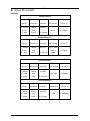
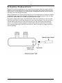
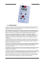
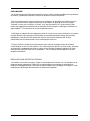
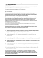
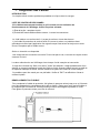
Time Electronics
1044 Voltage and Current Calibrator
Technical Manual
V1.1 09/01/11
Time Electronics Ltd
Botany Industrial Estate, Tonbridge, Kent, TN9 1RH
Tel: +44(0)1732 355993 Fax: +44(0)1732 770312
Email: [email protected]
Web Site: www.TimeElectronics.com
2
C ontents
1.
Introduc tion ........................................................................................................ 3
2.
S pec ific ations ..................................................................................................... 4
3.
Operation of the 1044 ........................................................................................ 6
3.1.
Preliminary .......................................................................................................... 7
3.2.
Setting a voltage output ..................................................................................... 7
3.3.
Setting a current output ..................................................................................... 7
3.4.
Measuring a voltage input .................................................................................. 8
3.5.
Measuring a current input .................................................................................. 8
4.
Operation of the 4-20mA S ys tem ...................................................................... 9
5.
B attery R eplac ement ....................................................................................... 10
6.
R ec alibration .................................................................................................... 11
7.
F ault Diagnos tic s ............................................................................................. 12
8.
G uarantee & S ervic ing ..................................................................................... 13
Manuel T ec hnique (F ranc ais ) ................................................................................. 14
T ec hnis c hes Handbuc h (Deuts c h)......................................................................... 28
All Time Electronics' instruments are subject to continuous development and improvement and in
consequence may incorporate minor detail changes from the information contained herein.
V1.1 09/01/11
Page |2
1044 Technical Manual
3
1. Introduc tion
The 1044 has been designed to offer solutions in many applications from the R&D lab to the
service engineer; in fact anywhere an accurate and low cost calibrator is needed.
We have used our experience in designing instrumentation to bring you the most versatile
and practical calibrator yet. The 1044 can source and measure voltage and current in one
compact unit and the 0.05% accuracy is ideal for simulation and calibration in most
engineering applications.
Being virtually foolproof in operation, the 1044 combines the advantages of digital accuracy
with analog controls. Progressing from the familiar functions of our popular 1030 calibrator,
the 1044 offers more ranges, better accuracy and the ability to measure as well as source,
making it even more of an asset.
The large, easy to read LCD display shows the actual output, even if the connected load
exceeds the specifications. This important feature eliminates the risk of large errors when
connecting to unknown loads. The display even shows if the battery becomes low.
In the source mode, voltage up to 20v and current up to 20mA may be generated in three
ranges, whilst in current source mode; the 1044 has a high 24V compliance voltage which is
ideal powering process control loops.
In the measurement mode, the range and function can be easily selected and will operate
as a multimeter. The measured input is accurately shown on the LCD display.
The 1044 is housed in a pocket sized, rugged ABS case and comes with a leatherette carry
case containing a compartment for storing test leads. Connections are by standard 4mm
plugs or by simply clamping the wires under the terminals.
The instrument is powered from an internal 9V alkaline battery (see page 10). Alternatively
the 1044 can be powered from an optional external linear AC/DC power supply (Time
Electronics code 7643). If power is supplied via other means, such as an in-vehicle 12V DC
socket, a 200mA fuse must be fitted to the socket adaptor.
V1.1 09/01/11
Page |3
1044 Technical Manual
4
2. S pec ific ations
RANGES
Voltage Source
Range
Resolution
Accuracy
0 - 200mV
100uV
± 0.05%
0 - 2V
1mV
+
0 - 20V
10mV
± 2 Counts
O/P Current
T/C per °C
20mA
± 150ppm
Voltage Measure
Range
Resolution
Accuracy
O/P Voltage
0 - 200mV
100uV
± 0.05%
<2V = 1MΩ
0 - 2V
1mV
+
0 - 20V
10mV
± 2 Counts
<20V =
10MΩ
T/C per °C
± 150ppm
Current Source
Range
Resolution
Accuracy
0 - 200uA
100nA
± 0.05%
0 - 2mA
1uA
+
0 - 20mA
10uA
± 3 Counts
O/P Voltage
T/C per °C
24V Max
± 200ppm
Current Measure
V1.1 09/01/11
Range
Resolution
Accuracy
0 - 200uA
100nA
± 0.05%
0 - 2mA
1uA
+
0 - 20mA
10uA
± 3 Counts
Page |4
Impedance
T/C per °C
10Ω
± 200ppm
1044 Technical Manual
5
OUTPUT NOISE
<30ppm of f.s. on voltage, <50ppm of f.s. on current
CONNECTIONS
Connections are made by 4mm banana type connectors or may be clamped using the wire
compression feature.
BATTERIES
1 off PP3, 6AM6, MN1604 or 6LR61 type battery.
Battery life is approximately 30 Hours depending on the current sourced. Alternatively an
optional 12V power supply can be plugged into the 2.5mm socket located on the end of the
unit, the tip of the plug should be positive.
PROTECTION
The 1044 can withstand open circuits, short circuits and reverse polarity up to 25V.
Additional protection is by an 20mm F100mA internal fuse.
CONSTRUCTION
Construction is in a durable plastic case with sliding cover for battery storage. Internally the
circuit is built on a single compact PCB with plug in display module. A carry case is also
supplied for moderate protection.
DIMENSIONS AND WEIGHT
Length 142mm (5.6”) x Width 75mm (2.9”) x Height 50mm (2.0”)
Weight 280g (0.6 lbs)
V1.1 09/01/11
Page |5
1044 Technical Manual
6
3. Operation of the 1044
CONTROLS
All the operator controls are located on the front panel with calibration adjustments located
inside the unit along with the input/output protection fuse. Refer to the Fault Diagnosis
section for more information.
V1.1 09/01/11
Page |6
1044 Technical Manual
7
3.1. Preliminary
Operation of the 1044 can be defined as four different procedures; voltage source, current
source, voltage measure and current measure.
For correct operation ensure that the battery low indicator is not showing in the display. The
output will only be indicated when the polarity switch is in either ‘normal’ or ‘reverse’
positions, not in the ‘off’ position. Be certain to check the polarity settings before connecting
the unit under test. The display will show a negative sign ‘-’ if the output is in reverse polarity
mode.
The display will show the actual applied output in source mode so if the value alters when
the unit under test is connected, the loading specifications might be exceeded. This is also
useful because it eliminates potential errors when connecting to an unknown U.U.T.
Always check the mode of operation and range values before connecting to the unit under
test or to the circuit being measured. If the 1044 will not source or measure the protection
fuse has probably blown due to an excessive current being applied to the unit. This can be
found inside the 1044 - refer to section 7, page 12 for more details.
3.2. Setting a voltage output
To set a voltage output, set the function switch to V and set the appropriate voltage
range.Set to the desired voltage by turning the output adjust multiturn potentiometer, the
output voltage shown in the display will alter. The unit under test may now be connected
observing the polarity.
3.3. Setting a current output
To set a current output, set the function switch to mA and set the appropriate current range
ensuring that the output adjust potentiometer is set to zero. Connect the unit under test. The
desired current can be set by turning the output adjust multiturn potentiometer where the
output current shown in the display will alter. To obtain a current reading, a load must be
connected to the output of the 1044.
Note that if the current output is set to its maximum but is not indicated on the display, the
output load is probably too high or the battery is low. Therefore reduce the loop resistance
or replace the battery.
V1.1 09/01/11
Page |7
1044 Technical Manual
8
3.4. Measuring a voltage input
To measure a voltage input select the V function and select the appropriate range. If the
input is unknown then choose the highest range. Select the measure mode and ensure that
the polarity switch is set to normal. The reading should now be displayed. If the display
shows the digit 1 with a blank character then the unit has over-ranged and must be switched
to the next highest range.
3.5. Measuring a current input
To measure a current input select the mA function and select the appropriate range. If the
input is unknown then choose the highest current range. Select the measure mode and
ensure that the polarity switch is set to normal. The reading should now be displayed. If the
display shows the digit 1 with a blank character then the unit has over-ranged and must be
switched to the next highest range.
V1.1 09/01/11
Page |8
1044 Technical Manual
9
4. Operation of the 4-20mA S ys tem
Introduction
A common use of the 1044 would be to simulate a transducer or measure the current flow in
a transducer loop. The following brief explanation, which is intended as a guideline only,
may help when operating the 1044 in a 4-20mA system.
The 4-20mA System
The basic requirement for any transducer with remote display is:
A) To use as few wires as possible.
B) That errors are not introduced into the signal from the transducer by the effects of
interference due to lead resistance.
C) To supply power to the transducer to enable amplifiers to be built into the transducer
when the signal produced by the sensing element is too small to be transmitted without
amplification.
In the 4-20mA system the transducer is supplied with D.C. power from the 2 wire line. The
transducer takes the current from the line proportional to the stimulus (i.e. pressure,
temperature, etc.). By measuring the current flowing in the line, the output of the transducer
can be monitored.
Since the signal is transmitted as a current, lead resistance and voltage drop do not affect
the accuracy. The basic requirements are therefore fulfilled using just two wires - the
minimum possible.
To enable a certain amount of standardisation, and to compensate for voltage drop or
variation in the supply, transducers are designed to operate over a wide voltage range,
usually between 15 and 30 volts, and to take a ‘zero’ current of 4mA and a full scale current
of 20mA.
The simplest 4-20mA current loop system consists of 3 parts, although often 2 parts are
incorporated into the same unit. The 3 main parts are 1) D.C. Power supply usually 24V.
2) 4 - 20mA current meter/recorder.
3) The transducer.
The D.C. power supply generates the drive power for the system and can be considered as
a battery.
The 4-20mA meter/recorder can be a passive moving coil mA meter with a zero offset. To
obtain a reading, current must be applied.
The transducer completes the loop and allows a current flow around the loop dependent on
the level of stimulus to the transducer. It can be considered as a potentiometer changing in
resistance to let between 4 and 20 mA to flow.
The 1044 can be used to check this system in either source or measure modes of operation
and has a 24V compliance voltage when set to current source mode that will power a loop.
V1.1 09/01/11
Page |9
1044 Technical Manual
10
5. B attery R eplac ement
Battery life is primarily dependent on the output currents drawn. With low output currents,
battery life can exceed 50 hours, but with high currents battery life may be reduced to less
than 5 hours. If a short battery life is experienced, rechargeable batteries may be used but
the battery must be charged externally.
Battery replacement is by sliding the rear panel up to its stopping point revealing the battery
compartment (see page 12 for diagram). The battery may now be replaced. Only use high
quality PP3, 6AM6, MN1604 or 6LR61 batteries that will not leak.
An optional mains power supply Time Electronics order code 7643 may be used to power
the instrument via the 2.5mm jack socket at the end of the instrument. This will cut out the
internal battery and power the 1044. Note that the tip of the 2.5mm jack plug should be
positive. The 1044 is protected against reverse polarity and will not function in this state.
If an external power supply other than the above is used it must be 12V supply and up to
200mA capability.
V1.1 09/01/11
P a g e | 10
1044 Technical Manual
11
6. R ec alibration
Introduction
Recalibration of the 1044 is essential to ensure both correct operation and maintain
accuracy. Recalibration is recommended annually.
This chapter gives calibration information.
Recalibration
This instrument is calibrated before it leaves the factory and the calibration controls will not
normally need adjustment, although periodic annual re-calibration is recommended. If recalibration is found to be necessary then follow this calibration procedure and adjust the
outputs to the published specifications.
All readings are taken from the front panel LCD display. Once calibrated, the 1044 would
only need verification that these readings are accurate. Equipment required for verification is
a digital multimeter with accuracy of at least 0.01% and a voltage and current source of
similar accuracy. Suggested items would be the Time Electronics 5075 High Resolution
Digital Multimeter and the Time Electronics 5018 Voltage and Current calibrator.
The calibrator procedure is as follows To adjust the trim pots follow the procedure described in fuse replacement.
The zero is factory set and should not require adjustment. Set the Output Adjust
potentiometer to full scale. All adjustments are to be within 0.05% ± 1 count and are taken
from the front panel LCD display.
1) Locate the 200mV trimmer pot on the rear of the LCD display. This can be reached via a
hole in the PCB. Set the 1044 to the 200mV range and adjust the trimmer to give 200mV.
2) Locate VR7 - 20V adjust. Select the 20V range and adjust VR7 for reading of 20V.
3) Locate VR6 - 2V adjust. Select the 2V range and adjust VR6 for a reading of 2V.
4) Locate VR5 - 20mA adjust. Select the 20mA current range and adjust VR5 for a reading
of 20mA.
5) Locate VR4 - 2mA adjust. Select the 2mA current range and adjust VR4 for a reading of
2mA.
6) Locate VR3 - 200uA adjust. Select the 200uA current range and adjust VR3 for a reading
of 200uA.
Once these readings have been completed, verification that the LCD display is reading
correctly is necessary. This is performed by injecting a known 200mV signal into the 1044
whilst in measure mode and set to the 200mV range. If the reading is out of specification,
the unit is faulty and must be repaired.
V1.1 09/01/11
P a g e | 11
1044 Technical Manual
12
7. F ault Diagnos tic s
Introduction
This section gives details of some possible problems and how to correct them.
Fault Check List
If the 1044 is completely dead without any indication of the display working, check
the following
1) Battery condition - replace battery.
2) Polarity of external power unit - reverse connections.
The 1044 indicates an output but there is not an output at the terminals.
1) The output protection fuse has blown. Check why this might have blown, commonly
caused by a signal being applied while still in the source mode. Replace with the correct
fuse.
Current output is not available.
Is there a load connected to the output? If not, current will not flow through the circuit.
The value selected on the display drops when the unit under test is connected.
This is a feature of the 1044 where the ‘actual’ value is indicated. This is probably
insufficient current drive from the 1044 because the unit under test is loading the output
beyond its 20mA drive capability. Check the unit under test for faults.
It might be due to a low battery condition. Check to see if ‘BAT’ is showing on the LCD
display.
Fuse replacement
To replace the output fuse slide the rear panel up to its stopping point revealing the battery
and fuse compartment. Carefully remove the old fuse and replace with a 100mA fuse.
Always replace with a 100mA fuse or serious damage to the 1044 could result. Slide the
rear panel firmly closed.
V1.1 09/01/11
P a g e | 12
1044 Technical Manual
13
8. G uarantee & S ervic ing
Guarantee Period.
This unit is guaranteed against defects in materials and workmanship for a period of one
year from its delivery to the customer.
We maintain comprehensive after sales facilities and the unit can, if necessary be returned
to us for servicing. During this period, Time Electronics Ltd will, at its discretion, repair or
replace the defective items. For servicing under guarantee, the instrument type and serial
number must always be quoted, together with details of any fault and the service required.
The purchaser of the instrument must prepay all shipping charges. Time Electronics Ltd will
pay return shipping charges.
This guarantee is void if servicing has been attempted by an unauthorised person or agent
If, during the guarantee period, failure is due to misuse or abuse of the unit, the repair will
be put in hand without delay and charged unless other instructions are received.
Please note that if you require a new UKAS Certificate during the warranty period, this will
be charged at the current rate on our price list.
Service after Guarantee Period.
Even after the guarantee period has expired, Time Electronics Ltd., can still service your
instrument. As the manufacturer, we have the specialised knowledge needed to keep your
instrument in peak condition and we also maintain a comprehensive spare parts service.
Please enclose details of the service required and your full company details including a
contact name when returning for servicing.
Returning Instruments
when returning instruments please ensure that they have been adequately packed,
preferably in the original packing supplied. Time Electronics Ltd will not accept
responsibility for units returned damaged. Please ensure that all units have details of the
service required and all relevant paperwork.
Send the instrument, shipping charges paid to:-
Time Electronics Ltd
Botany Industrial Estate, Tonbridge, Kent, TN9 1RH
Tel: +44(0)1732 355993 Fax: +44(0)1732 770312
Email: [email protected]
Web Site: www.TimeElectronics.com
Disposal of your old equipment
1. When this crossed-out wheeled bin symbol is attached to a product it means the
product is covered by the European Directive 2002/96/EC.
2. All electrical and electronic products should be disposed of separately from the
municipal waste stream via designated collection facilities appointed by the
government or the local authorities.
3. The correct disposal of your old appliance will help prevent potential negative
consequences for the environment and human health.
4. For more detailed information about disposal of your old appliance, please contact
your city office, waste disposal service or return to Time Electronics.
V1.1 09/01/11
P a g e | 13
1044 Technical Manual
14
Time Electronics
Calibrateur De Tension et de Courant 1044
Manuel Tec hnique (F ranc ais )
V1.1 09/01/11
P a g e | 14
1044 Technical Manual
15
Table des Matieres
1. Introduction
16
2. Caracteristiques Techniques
17
3. Fonctionnement du 1044
19
4. Fonctionnement du Systeme de 4-20mA
23
5. Remplacement de la Pile
24
6. Re-Etalonnage
25
7. Diagnostic des Pannes
26
8. Garantie et Entretien
27
Tous les instruments Time Electronics font l'objet d'une politique de développement et d'amélioration
continus et, par conséquent, il est possible que l'instrument présente quelques changements mineurs
par rapport aux informations figurant dans ce manuel.
V1.1 09/01/11
P a g e | 15
1044 Technical Manual
16
1. Introduction
Le 1044 a été conçu pour offrir des solutions dans de nombreuses applications allant du
laboratoire de recherche et développement au technicien d'entretien, en fait n'importe où un
calibrateur précis et peu onéreux est réclamé.
Nous avons utilisé notre expérience en matière de conception d'instrumentation pour vous
offrir le calibrateur le plus polyvalent et le plus pratique du moment. Le 1044 peut générer et
mesurer une tension et une intensité en une unité compacte et sa précision de 0,05% est
idéale pour la simulation et le calibrage dans la plupart des applications d’ingénierie.
Pratiquement indéréglable à l'usage, le 1044 combine les avantages de la précision
numérique et des commandes analogiques. Se basant sur les fonctions familières de notre
calibrateur 1030 populaire, le 1044 offre plus de plages, une plus grande précision et la
capacité de mesurer aussi bien que de générer, ce qui en fait un calibrateur encore plus
avantageux.
Le grand affichage à cristaux liquides aisé à lire indique la sortie réelle, même lorsque la
charge connectée dépasse les caractéristiques techniques. Cette importante fonction élimine
le risque de grosses erreurs en cas de connexion à des charges inconnues. L'affichage
indique même l'état de charge de la pile.
En mode source, une tension de jusqu'à 20V et une intensité de jusqu'à 20mA peuvent être
générées en trois plages, alors qu'en mode source d'intensité, le 1044 possède une tension
en courant constant élevée de 24V qui est idéale pour l'alimentation de boucles de
commande de processus.
En mode mesure, la plage et la fonction peuvent être facilement sélectionnées et l'instrument
va fonctionner en tant que multimètre. L'entrée mesurée est indiquée avec précision sur
l'affichage à cristaux liquides.
Le 1044 est logé dans un boîtier ABS solide de poche et est fourni avec un étui de transport
en similicuir contenant un compartiment pour ranger les cordons d'essai. Les connexions sont
assurées par des fiches de 4mm ou simplement par serrage des fils sous les bornes.
Une pile simple de 9V alimente l'unité ou une alimentation de 12V c.c. externe en option à
partir d'un transformateur d'alimentation, dont le code de commande Time Electronics est
7643, ou une prise d’allume-cigares dans une voiture peuvent être utilisés.
V1.1 09/01/11
P a g e | 16
1044 Technical Manual
17
2. Caracteristiques Techniques
PLAGES
Source de Tension
Intensité
Plage
Résolution
Précision
de Sortie
0 - 200mV
100uV
± 0.05%
20mA
0 - 2V
1mV
+±2
0 - 20V
10mV
Chiffres
Coefficient de
Température par
°C
± 150ppm
Mesure de Tension
Plage
Résolution
Précision
Impédance
d'entrée
Coefficient de
Température par
°C
0 - 200mV
100uV
± 0.05%
<2V = 1MΩ
± 150ppm
0 - 2V
1mV
+±2
0 - 20V
10mV
Chiffres
<20V =
10MΩ
Source D'Intensité
Plage
Résolution
Précision
Tension de
Sortie
Coefficient de
Température
par °C
0 - 200uA
100nA
± 0.05%
24V Max
± 200ppm
0 - 2mA
1uA
+±3
0 - 20mA
10uA
Chiffres
Mesure D'Intensité
Plage
Résolution
Précision
0 - 200uA
100nA
± 0.05%
0 - 2mA
1uA
+±3
0 - 20mA
10uA
Chiffres
V1.1 09/01/11
P a g e | 17
Impédance
Coefficient de
Température
par °C
10Ω
± 200ppm
1044 Technical Manual
18
BRUIT A LA SORTIE
<30 ppm en tension maximale, <50 ppm en intensité maximale.
CONNEXIONS
Les connexions sont assurées par des connecteurs de type banane de 4mm ou peuvent être
serrées à l'aide du système de compression des fils.
PILES
1 batterie de type PP3, 6AM6, MN1604 ou 6LR61.
La durée de vie de la pile est d'environ 30 heures, selon l'intensité générée. Alternativement,
une alimentation de 12V en option peut être enfichée dans la prise de 2,5mm située à
l'extrémité de l'unité, la pointe de la fiche doit être positive.
PROTECTION
Le 1044 peut supporter des circuits ouverts, des courts-circuits et une polarité inverse allant
jusqu'à 25V. La protection supplémentaire est assurée par un fusible interne.
STRUCTURE
L'unité se présente dans un boîtier en plastique solide équipé d'un couvercle coulissant pour
accéder à la pile. A l'intérieur, le circuit est construit sur une carte de circuit imprimé compacte
simple avec un module d'affichage enfichable. Un étui de transport est également fourni pour
une protection modérée.
DIMENSIONS ET POIDS
Longueur 142mm x largeur 75mm x hauteur 50mm
Poids 280g
V1.1 09/01/11
P a g e | 18
1044 Technical Manual
19
3. Fonctionnement du 1044
COMMANDES
Toutes les commandes de l'opérateur sont situées sur le panneau avant et les réglages
d'étalonnage sont situés à l'intérieur de l'unité, ainsi que le fusible de protection
d'entrée/sortie. Voir la rubrique Diagnostic des Pannes pour de plus amples informations.
V1.1 09/01/11
P a g e | 19
1044 Technical Manual
20
PRELIMINAIRE
Le fonctionnement du 1044 peut être défini comme quatre procédures différentes: génération
de tension, génération d'intensité, mesure de tension et mesure d'intensité.
Pour le fonctionnement correct, s'assurer que l'indicateur de pile faible ne s'affiche pas. La
sortie va seulement être indiquée lorsque le commutateur de polarité est soit en position
"normale" (norm) soit en position "inverse" (rev), pas en position "off" (hors tension). Bien
vérifier les réglages de polarité avant de brancher l'unité essayée. L'affichage va indiquer un
signe négatif "-" si la sortie est en mode de polarité inverse.
L'affichage va indiquer la sortie appliquée réelle en mode source; par conséquent, si la valeur
change lorsque l'unité essayée est branchée, les caractéristiques de charge peuvent être
dépassées. Cette fonction est également utile car ceci permet d'éliminer les erreurs
potentielles lors du branchement à une unité essayée inconnue.
Toujours vérifier le mode de fonctionnement et les valeurs de plages avant de brancher
l'unité essayée ou au circuit à mesurer. Si le 1044 ne génère pas ou ne mesure pas, le fusible
de protection a probablement sauté en raison d'une intensité excessive appliquée à l'unité.
Ceci peut être vérifié à l'intérieur du calibrateur - voir la rubrique Etalonnage pour de plus
amples informations.
REGLAGE D'UNE SORTIE EN TENSION
Pour définir une sortie en tension, régler le commutateur de fonction sur V et sélectionner la
plage de tension appropriée. Régler sur la tension désirée en tournant le potentiomètre
multitour d'ajustage de sortie; la tension de sortie indiquée sur l'affichage va changer. L'unité
essayée peut désormais être branchée en observant la polarité.
V1.1 09/01/11
P a g e | 20
1044 Technical Manual
21
REGLAGE D'UNE SORTIE EN COURANT
Pour définir une sortie en courant, régler le commutateur de fonction sur mA et sélectionner
la plage d'intensité appropriée en s'assurant que le potentiomètre d'ajustage de sortie est
réglé sur zéro. Brancher l'unité essayée. L'intensité désirée peut être réglée en tournant le
potentiomètre multitour; l'intensité de sortie indiquée sur l'affichage va changer. Pour obtenir
une mesure d'intensité, une charge doit être connectée à la sortie du 1044.
A noter que si la sortie en courant est réglée à son maximum mais n'est pas indiquée sur
l'affichage, la charge à la sortie est probablement trop élevée ou la pile est trop faible. Par
conséquent, réduire la résistance de boucle ou remplacer la pile.
V1.1 09/01/11
P a g e | 21
1044 Technical Manual
22
MESURE D'UNE ENTREE EN TENSION
Pour mesurer une entrée en tension, sélectionner la fonction V et sélectionner la plage
appropriée. Si l'entrée est inconnue, choisir la plage la plus élevée. Sélectionner le mode
mesure et s'assurer que le commutateur de polarité est réglé sur normale. La mesure devrait
désormais être affichée. Si l'affichage indique le chiffre 1 avec un blanc, l'unité a effectué un
dépassement de calibre et la plage la plus élevée suivante doit être sélectionnée.
MESURE D'UNE ENTREE EN COURANT
Pour mesurer une entrée en courant, sélectionner la fonction mA et sélectionner la plage
appropriée. Si l'entrée est inconnue, choisir la plage d'intensité la plus élevée. Sélectionner le
mode mesure et s'assurer que le commutateur de polarité est réglé sur normale. La mesure
devrait désormais être affichée. Si l'affichage indique le chiffre 1 avec un blanc, l'unité a
effectué un dépassement de calibre et la plage la plus élevée suivante doit être sélectionnée.
V1.1 09/01/11
P a g e | 22
1044 Technical Manual
23
4. Fonctionnement du Systeme de 4-20mA
INTRODUCTION
Le 1044 est fréquemment utilisé pour simuler un transducteur ou mesurer la circulation du
courant dans une boucle de transducteur. La brève explication suivante, présentée
uniquement à titre indicatif, peut faciliter l'utilisation du 1044 dans un système de 4-20mA.
LE SYSTEME DE 4-20mA
Les exigences de base pour n'importe quel transducteur à affichage à distance sont les
suivantes:
a) Utiliser le moins de fils possible.
b) Que les erreurs ne soient pas introduites dans le signal à partir du transducteur par les
effets de l'interférence ou de la chute de tension due à une résistance des conducteurs.
c) Alimenter le transducteur pour permettre aux amplificateurs d'être incorporés au
transducteur lorsque le signal produit par l'élément de détection est trop faible pour être
transmis sans amplification.
Dans le système de 4-20mA, le transducteur est alimenté en courant continu à partir d'une
ligne à 2 fils. Le transducteur prélève le courant de la ligne proportionnel au stimulus (c.-à-d la
pression, la température, etc.). En mesurant la circulation du courant dans la ligne, la sortie du
transducteur peut être contrôlée.
Etant donné que le signal est transmis en tant qu'intensité, la résistance des conducteurs et
la chute de tension n'affecte pas la précision. Les exigences de base sont par conséquent
remplies en utilisant uniquement deux fils - le minimum possible.
Pour permettre une certaine normalisation et pour compenser la chute de tension ou la
variation dans l'alimentation, les transducteurs sont conçus pour fonctionner sur une vaste
plage de tension, généralement entre 15 et 30 volts, et pour accepter une intensité "nulle" de
4mA et une intensité maximale de 20mA.
Le système à ventre de courant de 4-20mA le plus simple comprend 3 parties, bien que 2
parties soient incorporées dans la même unité. Les 3 parties principales sont:
1) Alimentation c.c. généralement de 24V.
2) Ampèremètre/enregistreur d'intensité de 4-20mA.
3) Transducteur.
L'alimentation c.c. génère la puissance de commande pour le système et peut être
considérée comme une batterie.
L'ampèremètre/enregistreur de 4-20mA peut être un appareil de mesure mA à cadre mobile
avec un décalage du zéro.
Le transducteur complète la boucle et permet au courant de circuler autour de la boucle,
selon le niveau de stimulus vers le transducteur. Il peut pratiquement être considéré comme
un potentiomètre changeant la résistance pour laisser passer le courant entre 4 et 20mA.
Le 1044 peut être utilisé pour vérifier ce système soit en mode source soit en mode mesure
et possède une tension en courant constant de 24V lorsque l'unité est réglée en mode source
d'intensité qui va alimenter une boucle.
V1.1 09/01/11
P a g e | 23
1044 Technical Manual
24
5. Remplacement de la Pile
La durée de vie de la pile dépend principalement des courants de sortie absorbés. Avec des
sorties à courant faible, la durée de vie de la pile peut dépasser 50 heures, mais avec des
sorties à courant fort, la durée de vie de la pile peut être réduite jusqu'à moins de 5 heures.
En cas de courte durée de vie de pile, il est possible d'utiliser des piles rechargeables mais la
pile doit être chargée hors de l'instrument.
Pour remplacer la pile, faire coulisser le panneau arrière jusqu'à son point d'arrêt pour révéler
le compartiment de la pile. La pile peut désormais être remplacée. N'utiliser que des piles de
haute qualité PP3, 6AM6, MN1604 ou 6RL61 qui ne vont pas fuir.
Une alimentation par secteur en option Time Electronics de code de commande 7643 peut
être utilisée pour alimenter l'instrument via la prise de jack de 3,5mm à l'extrémité de
l'instrument. Ceci coupe la pile et alimente le 1044. A noter que la pointe de la fiche de jack de
2,5mm doit être positive. Le 1044 est protégé contre la polarité inverse et ne fonctionnera pas
dans cet état.
Si une alimentation externe autre que celle susmentionnée est utilisée, il doit s'agir d'une
alimentation de 12V et d'une capacité allant jusqu'à 200mA.
V1.1 09/01/11
P a g e | 24
1044 Technical Manual
25
6. Re-etalonnage
INTRODUCTION
Le ré-étalonnage du 1044 est essentiel pour assurer un fonctionnement correct et maintenir
la précision de l'instrument. Un ré-étalonnage annuel est recommandé.
Ce chapitre présente des informations sur le ré-étalonnage.
RE-ETALONNAGE
Cet instrument est étalonné avant de quitter l'usine et les commandes d'étalonnage ne
nécessitent généralement pas d'ajustage, mais un ré-étalonnage annuel est recommandé. Si
le ré-étalonnage s'avère nécessaire, observer la procédure d'étalonnage suivante et ajuster
les sorties conformément aux caractéristiques techniques publiées.
Toutes les mesures sont relevées sur l'affichage à cristaux liquides du panneau avant. Une
fois le 1044 étalonné, il suffit de vérifier que ces mesures sont précises. L'équipement exigé
pour la vérification est un multimètre numérique d'une précision d'au moins 0,01% et une
source de tension et d'intensité de précision similaire. Nous suggérons l'utilisation d'un
multimètre numérique à haute définition 5075 Time Electronics et d'un calibrateur de tension
et d'intensité 5018 Time Electronics.
La procédure d'étalonnage est la suivante:
Pour régler le potentiomètre d'ajustage, observer la procédure décrite sous la rubrique
consacrée au remplacement du fusible.
Le zéro est réglé en usine et ne devrait nécessiter aucun ajustage. Régler le potentiomètre
d'ajustage de sortie sur sa valeur maximale. Tous les ajustages sont à 0,05% près ± 1 chiffre
et sont relevés sur l'affichage à cristaux liquide du panneau avant.
1) Localiser le potentiomètre d'ajustage de 200mV sur l'arrière de l'affichage à cristaux liquides. Il
est possible d'y accéder à travers un orifice dans la carte de circuit imprimé. Régler le 1044 sur
la plage de 200mV et ajuster le potentiomètre pour fournir 200mV.
2) Localiser l'ajustage VR7 - 20V. Sélectionner la plage de 20V et ajuster VR7 pour une
mesure de 20V.
3) Localiser l'ajustage VR6 - 2V. Sélectionner la plage de 2V et ajuster VR6 pour une mesure de 2V.
4) Localiser l'ajustage VR5 - 20mA. Sélectionner la plage d'intensité de 20mA et ajuster VR5 pour
une mesure de 20mA.
5)
Localiser l'ajustage VR4 - 2mA. Sélectionner la plage d'intensité de 2mA et ajuster VR4 pour
une mesure de 2mA.
6) Localiser l'ajustage VR3 - 200mA. Sélectionner la plage d'intensité de 200mA et ajuster VR3
pour une mesure de 200mA.
Une fois ces mesures effectuées, il est nécessaire de vérifier que l'affichage à cristaux
liquides fonctionne correctement. Pour ce faire, injecter un signal de 200mV connu dans le
1044 en mode mesure et régler sur la plage de 200mV. Si la mesure est non nominale, l'unité
est défectueuse et doit être réparée.
V1.1 09/01/11
P a g e | 25
1044 Technical Manual
26
7. Diagnostic des Pannes
INTRODUCTION
Ce chapitre décrit certains problèmes possibles et la façon dont les corriger.
LISTE DE CONTROLE DES PANNES
Si le 1044 est sans aucune tension et qu'il n'existe aucune indication de
fonctionnement de l'affichage, vérifier les points suivants:
1) Etat de la pile - remplacer la pile.
2) Polarité de l'entrée d'alimentation externe - inverser les connexions.
Le 1044 indique une sortie mais il n'y a pas de sortie au niveau des bornes.
1) Le fusible de protection de sortie a sauté. En trouver la raison; ce problème étant
généralement causé par l'application d'un signal lorsque l'instrument est toujours en mode
source. Remplacer par le fusible correct.
Sortie en intensité non disponible
Une charge est-elle connectée à la sortie? Si tel n'est pas le cas, le courant ne va pas circuler
à travers le circuit.
La valeur sélectionnée sur l'affichage chute lorsque l'unité essayée est connectée.
Il s'agit d'une fonction du 1044 où la valeur "réelle" est indiquée. Il s'agit probablement d'une
attaque en courant insuffisante à partir du 1044 car l'unité essayée charge la sortie au-delà de
sa capacité d'attaque de 20mA. Vérifier l'absence de panne au niveau de l'unité essayée.
Ce problème peut être causé par une pile faible. Vérifier si "BAT" est affiché sur l'écran à
cristaux liquides.
REMPLACEMENT DU FUSIBLE
Pour remplacer le fusible de protection, fairi glisser le panneau arriere jusqu a ce qu’il s’arrete
pour faire apparaitre le compartiment de la pile et fusible. Retirer avec soin l’ancien fusible et
le remplacer par un fusible de 100mA pourrait provoquer des degats importants au 1044.
Faire glisser le panneau arriere pour bien le refermer.
V1.1 09/01/11
P a g e | 26
1044 Technical Manual
27
8. Periode de Garantie
Cet instrument est garanti contre tout défaut de matériau et de fabrication pendant une
période d'un an à dater de sa livraison au client.
Nous assurons un service après-vente complet et, si nécessaire, l'unité peut nous être
retournée pour entretien. Au cours de cette période, Time Electronics Ltd réparera ou
remplacera l'article défectueux, à sa discrétion.
Pour l'entretien sous garantie, le type et le numéro de série de l'instrument doivent toujours
être indiqués, ainsi que les détails de toute défectuosité et de l'entretien exigé. L'acquéreur de
l'instrument doit régler d'avance tous les frais d'expédition. Time Electronics Ltd réglera tous
les frais de renvoi.
Cette garantie est annulée si une opération d'entretien a été tentée par une personne ou un
agent non agréé.
Si, au cours de la période de garantie, une panne est causée par le mauvais usage ou
l'usage anormal de l'instrument, les réparations seront effectuées sans retard et facturées
sauf réception d'instructions contraires.
SERVICE APRES LA PERIODE DE GARANTIE
Même après la période de garantie, Time Electronics Ltd peut toujours se charger du réétalonnage et de l'entretien de votre instrument. En tant que fabricant, nous possédons les
connaissances nécessaires pour conserver votre instrument en parfait état de marche et nous
assurons également un service de pièces de rechange complet.
Veillez à joindre les détails du service exigé ainsi que les coordonnées complètes de la
société, y compris le nom d'un contact.
RETOUR DES INSTRUMENTS
Lors du retour des instruments, s'assurer qu'ils ont été correctement emballés, de préférence
dans leur emballage d'origine. Time Electronics Ltd n'acceptera aucune responsabilité
pour les instruments retournés endommagés. Veiller à ce que tous les instruments soient
accompagnés des détails du service exigé et toute documentation appropriée y compris
l'adresse complète, le numéro de téléphone et le nom d'un contact. Retourner l'instrument,
frais d'expédition réglés d'avance à:
Time Electronics Ltd
Botany Industrial Estate, Tonbridge, Kent, TN9 1RH
Tel: +44(0)1732 355993 Fax: +44(0)1732 770312
E-Mail: [email protected]
Web Site: www.TimeElectronics.com
V1.1 09/01/11
P a g e | 27
1044 Technical Manual
28
Time Electronics
1044 SPANNUNGS - UND
STROMKALIBRATOR
Tec hnis c hes Handbuc h (Deuts c h)
V1.1 09/01/11
P a g e | 28
1044 Technical Manual
29
Inhalt
1. Einfuehrung
30
2. Spezifikation
31
3. Betrieb der 1044
33
4. Betrieb des 4 – 20mA-Systems
36
5. Batterietausch
37
6. Rekalibrierung
38
7. Fehlerdiagnose
39
8. Garantie
40
Alle Time Electronics' instrumente unterliegen einer staendigen Entwicklung und Verbesserung und
deswegen in Konsequenz, kann es kleinere Abweichungen vom technischen Handbuch geben.
V1.1 09/01/11
P a g e | 29
1044 Technical Manual
30
1. Einfuehrung
Die 1044 wurde fuer den Entwicklungsingeneur fuer vielfaeltige Anwendungen entwickelt,
ueberall dort, wo ein genauer und kostenguenstiger Kalibrator gebraucht wird.
Wir haben unsere gesamte Erfahrung eingebracht, um ein moeglichst vielseitiges und
praktisches Geraet anzubieten. Die 1044 kann sowohl als Spannungs- und Stromquelle und
zusaetzlich als Messgeraet mit einer Genauigkeit von 0.05% benutzt werden und ist damit
ideal fuer die Simulation and Kalibrierung in den meisten Ingeneursanwendungen
einsetzbar.
Die 1044 ist im Betrieb sehr robust und vereinigt die Vorteile von digitaler Genauigkeit mit
analoger Kontrolle. Ausgehend von unserem sehr beliebten Kalibrator 1030, haben wir der
1044 mehr Bereiche, eine hoehere Genauigkeit und die Moeglichkeit, sowohl als Quelle als
auch als Messinstrument benutzt zu werden, gegeben. Dadurch wird sie ein echtes
Wertstueck.
Das grosse, leicht lesbare Display zeigt den aktuellen Ausgangswert, auch wenn die
verbundene Last ausserhalb der Spezifikation liegt. Diese wichtige Eigenschaft eliminiert
das Risiko grosser Fehler, wenn die Last unbekannt ist. Das Display zeigt auch an, wenn
die Batterie schwach wird.
Im Quellmodus koennen Spannungen bis 20V und Stroeme bis 20mA in je 3 Bereichen
erzeugt werden, dabei hat die 1044 im Strom-quell-modus eine 24V-Kopfspannung, die
ideal fuer Prozesskontrollschleifen benutzt werden kann.
Im Messmodus koennen der Bereich und die Funktion sehr einfach ausgewaehlt werden
und das Geraet arbeitet dann als Multimeter. Der gemessene Eingangswert wird auf dem
Display dargestellt.
Die 1044 ist in einem ABS-Gehaeuse in Taschenformat eingebaut und wird in einer
Ledertragetasche mit einer Huelle fuer Kabel geliefert. Verbindungen koennen mit Standard
4mm Steckern oder durch Klemmen unter den Buchsen hergestellt werden.
Eine 9V-Batterie oder ein optionales 12V externes Netzteil (Time Ordercode 7643) oder der
Zigarettenanzuender des Autos koennen als Versorgungsspannung benutzt werden.
V1.1 09/01/11
P a g e | 30
1044 Technical Manual
31
2. Spezifikation
BEREICHE
Spannungsquelle
Bereich
Aufloesung Genauigkeit
0 - 200mV
100uV
± 0.05%
0 - 2V
1mV
+ ± 2 Count
0 - 20V
10mV
O/P
Stromt
T/C per °C
20mA
± 150ppm
Spannungsmessung
Bereich
Aufloesung Genauigkei
t
Eingangs
T/C per °C
Impedanz
0 - 200mV
100uV
± 0.05%
<2V = 1MΩ
0 - 2V
1mV
+±2
0 - 20V
10mV
Count
<20V =
10MΩ
± 150ppm
Stromquelle
Bereich
Aufloesung Genauigkeit
O/P
T/C per °C
Spannung
0 - 200uA
100nA
0 - 2mA
1uA
0 - 20mA
10uA
± 0.05%
+
24V Max
± 200ppm
Impedanz
T/C per °C
10Ω
± 200ppm
± 3 Count
Strommessung
Bereich
V1.1 09/01/11
Aufloesung Genauigkeit
0 - 200uA
100nA
± 0.05%
0 - 2mA
1uA
+
0 - 20mA
10uA
± 3 Count
P a g e | 31
1044 Technical Manual
32
AUSGANGSRAUSCHEN
<30 ppm von Vollausschlag bei Spannung,
<50 ppm von Vollausschlag bei Strom.
VERBINDUNGEN
Verbindungen werden mit 4 mm Bananensteckern oder durch Klemmen unter die Buchsen
hergestellt.
BATTERIEN
1 Batterie Typ PP3 oder 6AM6 oder MN1604 oder 6LR61
Die Batterielebensdauer betraegt ca 30 Stunden, abhaengig vom gezogenen Strom.
Alternativ kann ein 12V-Netzteil in die 3.5 mm Buchse am Kopfende eingesteckt werden,
plus auf dem Pin.
SCHUTZ
Die 1044 vertraegt offene Schaltungen, ist kurzschluss sicher und vertraegt auch eine
Verpolung bis 25 V.Zusaetzlicher Schutz erfolgt durch eine interne Sicherung.
KONSTRUKTION
Die Konstruktion ist ein robustes Plastikgehaeuse mit einer Oeffnung fuer die Batterie. Der
Schaltkreis befindet sich auf einem PCB mit aufgestecktem Display. Ferner wird eine
Tragetasche fuer einen moderaten Schutz mitgeliefert.
DIMENSIONEN UND GEWICHT
Laenge 142 mm x Breite 75 mm x Hoehe 50 mm
Gewicht 280 g
V1.1 09/01/11
P a g e | 32
1044 Technical Manual
33
3. Betrieb der 1044
KONTROLLE
Alle fuer den Betrieb notwendigen Kontrollen sind auf der Frontplatte angebracht, die
Kalibrierungspotentiometer sind jedoch innen neben der Sicherung. Im Fehlerdiagnostiksektor gibt es weitere Hinweise.
VORLAEUFIGES
Der Betrieb der 1044 kann fuer 4 Prozeduren definiert werden: Spannungsquelle,
Stromquelle, Spannungsmessung und Strommessung.
Fuer korrekten Betrieb sollte auf dem Display die Batterie keine Entladung anzeigen. Der
Ausgang wird nur dann auf dem Display angezeigt, wenn der Polaritaetsschalter entweder
auf ‘normal’ oder ‘reverse’ eingstellt ist., das Display zeigt nicht in der ‘OFF-‘ -Position an.
Auf die korrekte Polaritaet sollte vor dem Verbinden geachtet werden. Das Display zeigt ein
Minuszeichen ‘-‘ bei Verpolung.
Das Display zeigt in Quellmodus den aktuellen Wert, sollte such dieser veraendern, so ist
evtl. der Ladezustand veraendert. Das kann sehr praktisch sein, wenn man die 1044 an
eine unbekannte Einheit angeschliesst.
Man sollte immer den Bereich, die Polaritaet und den Betriebsmodus ueberpruefen, bevor
man die Einheit anschliesst. Sollte die 1044 weder als Quelle noch im Messmodus
funkitionieren, so ist wahrscheinlich die Sicherung wegen zu hoher Last durchgebrannt.
Diese finden Sie im Innern des Geraetes –siehe Beschreibung: Kalibrierung.
EINSTELLUNG DES SPANNUNGSAUSGANGS
Um eine Ausgangsspannung einzustellen, setze den Funktionsschalter auf ‘V’ und waehle
den entsprechenden Bereich. Die Ausgangsspannung wird dann mit dem Potentiometer
eingestellt, automatisch veraendert sich die Displayanzeige. Bei Beachtung der richtigen
Polaritaet kann die Testeinheit jetzt angeschlossen werden.
V1.1 09/01/11
P a g e | 33
1044 Technical Manual
34
EINSTELLEN EINES AUSGANGSSTROMS
Um einen Ausgangsstrom einzustellen, muss der Funktionsschalter auf mA gestellt und ein
angemessener Bereich ausgewaehlt und mit dem Potentiometer der Strom auf Null gesetzt
werden.Verbinde die zu testende Einheit.Danach kann der gewuenschte Strom durch das
Potentiometer eingestellt und auf dem Display beobachtet werden.Um eine Stromanzeige zu
erhalten, muss eine Last zugeschaltet sein.
Bemerke,wenn der Stromausgang auf Maximum steht , aber nicht angezeigt wird, dann ist
entweder die Ausgangslast zu hoch oder die Batterie ist leer.Deswegen muss entweder der
Widerstand verkleinert oder die Batterie ausgetauscht werden.
V1.1 09/01/11
P a g e | 34
1044 Technical Manual
35
MESSUNG EINER EINGANGSSPANNUNG
Um eine Eingangsspannung zu messen , waehle die V- Funktion und einen erwarteten
Bereich.Falls die Spannung gaenzlich unbekannt ist , waehle auf jeden Fall den hoechsten
Bereich.Waehle den Messmodus und versichere Dich , dass der Polaritaetsschalter auf
‘Normal’ steht.Nach Herstellung der Verbindung wird die Spannung angezeigt.Zeigt das
Display eine 1 und einem Leerzeichen , dann besteht Overflow und der naechst hoehere
Bereich muss gewaehlt werden.
MESSUNG EINES EINGANGSSTROMS
Um den Eingangsstrom zu messen , waehle mA-Funktion und einen erwarteten
Bereich.Wenn der Strom gaenzlich unbekannt ist ,dann waehle den hoechsten
Bereich.Waehle den Messmodus und setze den Polaritaetsschalter auf ‘Normal’.Das Display
sollte nun anzeigen.Falls das Display eine 1 sowie ein blank zeigt , dann besteht Overflow
und der naechst hoehere Bereich muss ausgewaehlt werden.
V1.1 09/01/11
P a g e | 35
1044 Technical Manual
36
4. Betrieb Als 4 - 20mA – System
EINFUEHRUNG
Eine allgemeine Anwendung ist die Simulation eines Uebertragers oder die Messung eines
Stroms in einer Uebertragungsschleife. Die folgende kurze Erklaerung, die nur als
Anregung dienen soll, moege dabei helfen die 1044 in einem 4 – 20mA-System zu
benutzen.
DAS 4 – 20mA-SYSTEM
Die Grundlegende Forderung fuer jeden Uebertrager mit einem externen Display ist:
a) Benutze so wenig Verbindungen wie moeglich.
b) Es sollten keine Fehler in das Signal vom Uebertrager durch Interferenzen oder durch
Spannungsverluste von Leitungen erzeugt werden koennen.
c) Falls das Signal am Sensor zu klein ist, muss die Moeglichkeit bestehen den
Uebertrager und einen zusatzlichen Verstaerker mit einer externen Spannung zu versorgen.
In einem 4 – 20 mA-System wird der Uebertrager mit einer 2- Draht-Verbindung
versorgt.Der Uebertrager nimmt Strom entsprechend dem Stimulus ( Druck , Temperatur,
etc)auf.In dem man den Linienstrom misst,kann der Ausgang des Uebertragers dargestellt
werden .
Da das uebertragene Signal ein Strom ist , koennen der Linienwiderstand und ein
Spannungsverlust die Genauigkeit nicht beeintraechtigen.Die Basisforderung wird dadurch
erfuellt , das man nur 2 Draehte nimmt- das moegliche Minimum.
Um zu standadisieren , werden Uebertrager in der Regel fuer einen Spannungsbereich von
15 – 30 V und einen ‘Nullstrom ‘ von 4 mA und einen Vollausschlag von 20 mA ausgelegt.
Das einfachste 4 – 20 mA-System enhaelt 3 Teile , obwohl haeufig 2 Teile bereits eine
Einheit bilden.Diese 3 Teile sind;
1) DC –Netzteil , normal 24 V
2) 4 – 20 mA Strommessgeraet
3) Der Uebertrager
Das Netzteil kann als Batterie betrachtet werden und uebernimmt die Versorgung des
Systems.
Das 4 – 20mA –Messgeraet kann ein passives Drehspulinstrument sein mit Nulloffset, in
jedem Fall muss ein Strom indiziert werden .
Der Uebertrager komplettiert die Regelschleife und er erlaubt , dass ein Strom in
Abhaengigkeit von dem Stimulus fliessen kann.
Die 1044 kann benuzt werden entweder um das System zu ueberpruefen oder die
Betriebsmoden zu messen und schliesslich kann es die 24 V –Versorgung uebernehmen ,
wenn es im Strom-Quell-modus betrieben wird.
V1.1 09/01/11
P a g e | 36
1044 Technical Manual
37
5. Batterieaustausch
Die Lebensdauer der Batterie haengt vom gezogenen Strom ab.Mit kleinen
Ausgangsstroemen kann die Lebensdauer groesser als 50 std sein, aber mit grossen
Stroemen kann sie durchaus auf 5 std limitiert sein.Bei kurzen Lebensdauern werden
wiederladbare Batterein von Vorteil sein.Das Geraet kann von extern geladen werden.
Auf der Rueckseite des Geraets kann das Batteriefach geoeffnet werden.Danach kann die
Batterie austauscht werden. Geeignete Batterien sind die Typen PP3 , 6AM6, MN1604
oder6LR61 , die nicht auslaufen.
Ferner kann ein externes Netzteil von Time mit dem Bestellcode 7643 verwendet werden ,
in dem man es in den 3.5 mm Sockel am Kopfende des Geraetes einsteckt.
Damit wird automatisch die Batterieversorgung abgetrennt und die 1044 von extern
betrieben.Bemerke , sollten Sie eine eigenes Netzteil verwenden , dann muss der positive
Pol eingefuehrt werden. Andernfalls ist das Geraet nicht Betriebsbereit , ist jedoch gegen
Verpolung geschuetzt.
Die benoetigte externe Spannung ist 12 V und sollte eine Last von 200mA treiben koennen.
V1.1 09/01/11
P a g e | 37
1044 Technical Manual
38
6. Rekalibrierung
EINFUEHRUNG
Die Rekalibrierung der 1044 ist wichtig , um beides -korrekten Betrieb und Messgenaigkeitzu erhalten.Es wird empfohlen die Einheit jaehrlich zu rekalibrieren.
Dieses Kapitel gibt Informationen zur Kalibrierung.
REKALIBRIERUNG
Das Geraet verlaesst kalibriert die Fabrik und normalerweise benoetigt das Geraet keine
Ueberpruefung der Kalibrierung, dennoch empfehlen wir eine jaehrliche Rekali-Bierung.Falls
dennoch eine Re-Kalibrierung notwendig ist, dann folgen Sie bitte folgenden Vorschriften.
Alle Werte werden vom Frontplattendisplay entnommen.Einmal kalibriert, benoetigt die
1044 nur eine Verifizierung der exakten Werte.Sie benoetigen dazu ein Digitalmultimeter mit
0.01 % Genauigkeit und eine Strom – und Spannungsquelle mit aehnlicher
Genauigkeit.Geeignete Geraete sind Das Time Electronics Multimeter 5075 und der Time
Electronics Strom-/Spannungskalibrator 5018.
Die Kalibrierprozedur ist wie folgt:
Um die Potentiometer zu justieren folge der Beschreibung :Sicherungsaustausch.
Die Nulleinstellung bedarf keiner Korrektur.Setze das Ausgangspotentiometer auf
Vollausschlag.Alle Abgleiche sollen innerhalb +/- 0.05 % +/- 1 Count sein und sollen vom
Frontplattendisplay abgelesen werden.
1) Finde das 200mV-Potentiometer auf der Rueckseite des Displays.Es kann durch ein
Loch in der Leiterplatte erreicht werden.Stelle an der 1044 den 200mV-Bereich ein und
justiere auf 200mV
2) Finde VR7-20V Potentiometer. Waehle 20 V –Bereich und justiere mit VR7 auf 20 V auf
dem display.
3) Finde VR 6-2V-Bereich , waehle 2V-Bereich und justiere mit VR6 auf 2V auf dem
display.
4) Finde VR 5-20mA;waehle 20mA Strombereich und justiere mit VR 5 auf 20mA auf dem
Display.
5) Finde VR4 2mA; waehle 2 mA-Strombereich und justiere mit VR 4 2mA auf dem Display.
6) Finde VR3 –200 mikro A; waehle 200mikroA und justiere mit VR 3 auf 200 mikroA.
Wenn alle diese Werte korrekt sind , muss das LCD-Display ueberprueft werden.Dieses
wird dadurch erreicht , dass man ein bekanntes 200mV-Signal auf das Geraet gibt waehren
man im Messmodus und 200mV-Breich arbeitet.Falls das Display nicht korrekt anzeigt, dann
ist die Einheit defekt und muss eingeschickt werden.
V1.1 09/01/11
P a g e | 38
1044 Technical Manual
39
7. Fehlerdiagnose
EINFUEHRUNG
Dieses Kapitel beschaeftigt sich im Detail mit moeglichen Problemen und wie man sie
korrigieren kann.
FEHLERDIAGNOSELISTE
Falls die 1044 total tot ist , ohne jegliche Anzeige , dann ueberpruefe das Folgende:
1) Batteriezustand-Ersetze die Batterie.
2) Polaritaet des externen Netzteils – tausche die Polaritaet.
Die 1044 zeigt einen Ausgang auf dem Display, aber es ist kein Signal auf den Buchsen.
Die Ausgangsschutzsicherung ist defekt.Ueberpruefe zunaechst wie es dazu kommen
konnte, normalerweise weil ein Signal auf das Geraet gegeben wurde, aber man befand
sich noch im Quellmodus.Ersetze die Sicherung.
Kein Stromausgangssignal
Ist eine Last mit dem Ausgang verbunden? Falls nicht, so wird auch kein Strom fliessen.
Der eingestellte Wert auf dem Display sinkt , wenn die zu pruefende Einheit
angeschlossen wird.
Dieses ist ein Feature der 1044 wo der ‘aktuelle ‘ Wert angezeigt wird. Offensichtlich wird
zuwenig Strom von der 1044 getrieben, das liegt daran , dass die Last hoeher als die
Maximallast von 20 mA.Ueberpruefe , ob die Testunit in Ordnung ist.
Es kann aber auch am zu niedrigen Ladezustand der Batterie liegen.Ueberpruefe , ob ‘Bat’
auf dem Display angezeigt wird.
SICHERUNGSAUSTAUSCH
Um die Ausgangssicherung zu ersetzen, muss man die Rucksette sowen oeffnen, sodass
die Batterie und der Sicherungskasten sichtbar werden. Entferne die alte Sicherung
vorsichag und seize eine 100mA-Sicherung neu ein. Immer eine 100mA Sicherung
nehmen, amit die 1044 keinen Schaden erleidet. Schliesse die Ruecksette wieder fest.
V1.1 09/01/11
P a g e | 39
1044 Technical Manual
40
8. Garantie
GARANTIEPERIODE
Dieses Instrument unterliegt einer Garantiezeit von einem Jahr, gerechnet ab Auslieferung
zum Kunden.Die Garantie gilt fuer Material- und Fertigungsmaengel.
Wir unternehmen einige After-Sales –Anstrengungen und die Einheit kann falls notwendig
ins Werk zurueckgeschickt werden.Waehrend dieser Zeit ersetzt oder repariert Time
Electronics Ltd defekte Bauteile.
Fuer den Service geben sie bitte jeweils den Instrumententyp und die Seriennummer mit
Ferner sollte eine detailiierte Fehlerbeschreibung beiliegen.Der Kaeufer des Instruments
uebernimmt die Transportkosten zu Time Electronics Ltd, waehrend TE die
Ruecktransportkosten uebernimmt.
Die Garantie erlischt sowie eine nicht authorisierte Person oder die Agentur eine Reparatur
versucht hat.
Falls,waehrend der Garantieperiode, die Einheit durch Falschbetrieb oder durch
Missbrauch beschaedigt wird, dann ist die Reparatur kostenpflichtig, es sei denn es werden
durch Verhandlung andere Absprachen getroffen.
SERVICE NACH ABLAUF DER GARANTIEPERIODE
Auch nach Ablauf der Garantie uebernimmt TE selbstverstaendlich die Reparatur und die
Rekalibrierung und den Service der Geraete.Durch unser Knowhow als Hersteller und durch
und grosses Ersatzteillager sind wir in der Lage ,Ihr Produkt weiter in Spitzenkondition zu
erhalten.
Bitte teilen sie unbedingt den gewuenschten Service und eine Kontaktperson schriftlich mit.
RUECKSENDUNG VON GERAETEN
Falls sie Geraete zurueckschicken, achten Sie bitte auf eine adaequate Verpackung, nach
Moeglichkeit sogar in der Originalverpackung.TE uebernimmt keine Verantwortung fuer
Transportschaeden.Stellen sie sicher, dass die Transportpapiere ordnungsgemaess
sind und Namen, Adresse, Telefon und Kontaktperson enthalten. Senden Sie das
Instrument, Frachtkosten im Voraus bezahlt, an:
Time Electronics Ltd
Botany Industrial Estate, Tonbridge, Kent, TN9 1RH
Tel: +44(0)1732 355993 Fax: +44(0)1732 770312
E-Mail: [email protected]
Web Site: www.TimeElectronics.com
V1.1 09/01/11
P a g e | 40
1044 Technical Manual