1
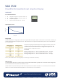
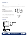
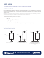
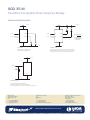
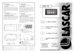
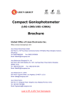
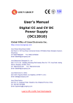
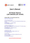
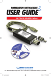
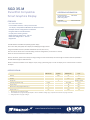
SGD 35-M PanelPilot Compatible
Smart Graphics Display
ORDERING INFORMATION
FEATURES
Standard Display
(Panel meter, fixing kit,
quick start guide)
SGD 35-M
USB Cable
(Type A to mini-B)
CABLE USB A-MF
• 3.5” colour TFT screen
• Use PanelPilot software, to setup and customise
the display. Compatible with Windows XP, 2000, Vista and 7
• Multiple voltmeter configurations included free
• Programmable via the USB interface
• Simple panel mounting solution
• Wide operating voltage of 4V – 30V d.c.
• Measures voltage from 0 – 40V d.c.
• Digital hold
The SGD 35-M is a PanelPilot Compatible graphics display
with a 320 x 240 pixel (QVGA) colour display and USB programming interface.
Using the PanelPilot software (available for Windows XP, 2000, Vista and 7),
users are able to choose from an ever-increasing number of configurations (six voltmeters at launch)
which can then be customised to their needs.
Colours, text labels, splash screen and input voltage scaling can all be customised by the user through the software and then uploaded to
the SGD 35-M through the USB connection.
Panel or enclosure installation of the display is simple, using a panel fixing clip to mount the display, and 4 screw terminals to connect
the inputs.
SPECIFICATIONS
Minimum
Accuracy
Typical 0.05
Linearity
Sample rate
Maximum
Unit
0.1
%
±1*
Count
Samples / second
3
0 (+32)
+40 (+104)
°C (°F)
Supply voltage
4
30
V d.c.
Measurement voltage (single ended only)**
0
40
V d.c.
50
300
mA
Operating temperature range
Supply current ***
* Depending on user calibration settings
** The SGD 35-M uses a programmable gain amplifier. There are 8 different voltage ranges, to optimise the resolution. See page 2 for details.
*** Voltage dependent. See graph on Page 2.
www.lascarelectronics.com Specifications liable to change without prior warning Issue 2 12/2011 S.L Applies to SGD 35-M
Page 1 of 5
SGD 35-M PanelPilot Compatible Smart Graphics Display
HARDWARE
Screw Terminal Functions
1 IN2 Analogue voltage input 2 (maximum of 40V d.c.)
2 IN1 Analogue voltage input 1 (maximum of 40V d.c.)
3 0V
0V power supply input
4 V+
Positive power supply input (4V – 30V d.c.)
Typical Supply Current
Current (mA)
300
150
0
4
30
13
Voltage (V)
Voltage Input
The SGD 35-M features 2 voltage inputs, which use a Programmable Gain Amplifier (PGA) to make the best use of available resolution (the
smallest voltage range offers the highest resolution). Each channel can be programmed independently, with the option of eight different
input voltage ranges:
The input voltage range is decided using the two voltages that the user enters in the
scaling section of the Panel Pilot software. The software uses the smallest range
available, which can accommodate both of the voltages entered by the user. The
absolute maximum voltage input is 40V d.c.
Voltage Range (V)
Resolution (mV)
0 - 1.25
0.3
0 - 2.5
0.6
0-4
0-5
1.0
1.2
For example:
0-8
2.0
0 - 10
2.4
0 - 20
4.9
Entering a voltage scale of 0 – 30V in the software will use the 0 – 40V range.
Entering a voltage scale of 0 – 3V in the software will use the 0 – 4V range.
Entering a voltage scale of 5 – 15V in the software will use the 0 – 20V range.
0 - 40
9.8
Note: V+, IN1 and IN2 share a common ground (i.e. not floating or isolated from each other).
USB connection
A ‘Type A to Mini-B’ USB cable is required to program and customise the SGD 35-M. It typically takes 10 seconds to send a configuration,
with an additional 5 seconds needed for the hardware to reset.
The SGD 35-M can be powered directly from USB and is compatible with both USB 1.1 and USB 2.0. The screw terminals and advanced
connector can remain connected whilst using USB, but it is not necessary for V+ to be powered.
www.lascarelectronics.com Specifications liable to change without prior warning Issue 2 12/2011 S.L Applies to SGD 35-M
Page 2 of 5
SGD 35-M PanelPilot Compatible Smart Graphics Display
Display
The display is a 3.5” TFT panel, with a resolution of 320 x 240 pixels and a 16-bit color depth. Any graphics that are uploaded to the
meter are automatically converted to this specification. A resistive touchscreen is fitted, for use with supporting applications. Clean the
screen with a damp, soft, lint free cloth.
Panel Mounting
The SGD 35-M can be fitted into panels 1mm - 3mm deep.
A silicone seal is included to improve fitting on thin panels.
Panel cut-out is 92mm x 74mm.
NOTE: The display is NOT protected against moisture or dust.
Advanced Connector
The DIL IDC socket provides an alternative connection method to the
screw-teminals (V+, 0V, IN1 and IN2 are duplicated). It also includes
provision for future expansion using data buses (SPI and I2C) and
alarm ouputs. Some expansion options may require an additional
interface board - Visit www.panelpilot.com for information on which
features are currently supported.
14
13
0V
DIGI6
DIGI4
DIGI2
ALM2
V+
IN2
DAC1
DIGI5
DIGI3
DIGI1
ALM1
0V
IN1
2
1
DIMENSIONS
All dimensions in mm (inches)
96.0 3.8
52.7 2.1
78.5 3.1
70.1 2.8
Viewing Area
Panel Cut-out: 92 x 75 (3.62 x 2.95)
2.7 0.1
18.7 0.7
17.7 0.7
39.9 1.6
16.2 0.6
8.7 0.3
5.7 0.2
10.0 0.4
8.7 0.3
24.3 1.0
8.0 0.3
23.8 0.9
23.3 0.9
10.5 0.4
TERMINALS USE
WIRE SIZE = 16-26 AWG
www.lascarelectronics.com Specifications liable to change without prior warning Issue 2 12/2011 S.L Applies to SGD 35-M
Page 3 of 5
SGD 35-M
PanelPilot Compatible Smart Graphics Display
PANELPILOT SOFTWARE
Lascar’s PanelPilot software is available for download free of charge from www.PanelPilot.com. Easy to install and use, the control software
runs under Windows 2000, XP, Vista and 7. The software is used to setup the appearance and operation of the meter and then upload these
settings to the meter.
Multiple types of voltmeter are supplied with the software. Additional voltmeters and functions will be made available using an annual subscription based service through www.PanelPilot.com. See the website for details of available meters.
The software allows the following parameters to be configured:
• Meter type
• Text labels (including units and graph labels)
• Background, graph segment and text colors
• Input scaling / calibration (at two points)
• Decimal points (entered during scaling)
• Splashscreen image selection (to display a user image, such as a logo, when the meter is powered up)
VARIOUS OPERATING MODES
4 - 30 V
4 - 30V
4 - 30V
0 - 100V
(V1)
V+
0 - 40V
V+
IN1
V+
910K
IN1
0 - 2A
IN1
100K
4W
V2
0V
0V
0V
Measuring a voltage source
0V
0V
Measuring 0 - 2 amps current range.
Use a 1 Ω resistor, with a 4W rating.
Setup scaling in software: 0V = 0.00 and 2V = 2.00
0V
Measuring 0 - 100V (d.c. only).
Input a known voltage of between 0 and 100V (V1)
Measure the voltage between IN1 and 0V (V2)
Setup scaling in software: 0V = 0.0
V2 = V1 (Enter with the same number of decimal points,
i.e 50.0)
www.lascarelectronics.com Specifications liable to change without prior warning Issue 2 12/2011 S.L Applies to SGD 35-M
Page 4 of 5
SGD 35-M
PanelPilot Compatible Smart Graphics Display
VARIOUS OPERATING MODES
4 - 30V
4 - 30V
R
IN1
0 - 40V
IN2
0 - 40V
DIGI1
0 - 40V
DIGI2
0 - 40V
IN1
ALM1
IN2
ALM2
R
R = (VS - VL)
IL
VS = Supply voltage
VL = LED Voltage drop
IL = LED current
0V
0V
DIGITAL HOLD
ALARM OUTPUTS
DIGI1 will hold the display for IN1
DIGI2 will hold the display for IN2
Applications that feature an alarm can be connected as above.
ALM1 and ALM2 must not sink more than 10mA maximum each.
If supply voltage varies, use an appropriate voltage regulator.
4 - 30V
V-
4 - 20mA
IN1
50
200mW
0V
0V
MEASURING 4-20mA
Use a 50 Ω resistor with a 200mW rating.
Setup scaling in software 0.2V=4.0 and 1V=20.0
Cannot be loop powered. Supply must be isolated from current loop.
Module House
Whiteparish, Salisbury
Wiltshire SP5 2SJ
UK
T +44 (1794) 884567
F +44 (1794) 884616
E [email protected]
4258 West 12th Street
Erie
PA 16505
USA
T +1 (814) 835 0621
F +1 (814) 838 8141
E [email protected]
8th Floor, China Aerospace Centre
143 Hoi Bun Road
Kwun Tong, Kowloon
HONG KONG
T +852 2389 6502
F +852 2389 6535
E [email protected]
www.lascarelectronics.com Specifications liable to change without prior warning Issue 2 12/2011 S.L Applies to SGD 35-M
Page 5 of 5