1
GSM BASED EMERGENCY NOTIFICATION VIA SMS
MOHD RIZUAN BIN MAT AMIN
A thesis submitted in fulfillment of the
requirements for the award of the degree of Bachelor of
Engineering (Electrical - Telecommunication)
Faculty of Electrical Engineering
Universiti Teknologi Malaysia
JULY 2012
I
I
n
I hereby doclare that tltis thesis entitled *GSM Based hrcrgency Notification via SI49' is the
rpzult of my own research c!rc€pt cited in the rcference. The thesis has not
degree and is not concuneirtly zubmitted in
Namp
DAt€
:
MOHD RIZUAI{ BIN MAT AMIN
:5JT.JLY2O12
berl
accepd€d
cadideturc ofany otlrerdegree.
for any
To my parents,
Mat Amin Bin Sulong & Late Zainun Binti Ali
To my adoptive mother,
Maimunah bt Ismail
To my siblings
Kamariah, Yusuf, Asro, Rohayu, Mariati
To my helpful friends
Zaki, Shafiq, Najib,
To all my lovely course mates
4SET 2011/2012
To my specials
Nurul Syazlin Binti Saharin
Thank you for always with my side along to complete this
journey, I very appreciate with your support and help.
Thank you for all the memories...........
ii
ACKNOWLEDGEMENT
Alhamdulillah and thanks to Allah S.W.T because I can finish my work for final
year project with successfully.
I am very thankful to everyone who all supported me for I have completed my
project effectively and moreover on time.
I am equally grateful to my supervisor Pn Fareha Bt Abd Rahman. She gave me
moral support and guided me in different matters regarding the topic in how to do my
research. She had been very kind and patient while suggesting me the outlines of this
project and correcting my doubts. I thank her for her overall supports.
Besides that, l also thank to Mr Hamdan, Phd student at telecom lab because help me a
lot while doing the program for the PIC.
iii
ABSTRACT
Human nowadays are exposed to the roadside danger especially women.
Women are especially prone to be the victims of snatch thieves. If this incident happens,
they do not know how to handle the situation and become panic for instantly losing all
of the important things such as hand phone, driving license, and sometimes jewelry. At
a time like this, all women would wish to have a device that can send an auto and
immediate SOS message instantaneously to a close friend or to a nearby police station.
This project is to design such a device. A device consists of small transmitter,
GPS receiver and GSM modem that can be used to send an immediate message to the
preselected numbers within a short time. The device should also give information on the
exact location of the incident. In other words, a system is created so that it could be a
backup device if the entire telecommunication devices are taken away. The victim does
not have to call the emergency number like 999 and describe the situation or to write a
message, but she just need to press a button. In a short time, the auto message will be
sent.
The major part of this project is on writing the source code using C language so
that the GPS module and GSM modem can be connected together and functioning well.
When the GPS module received the information about longitude and latitude, the
information will be send to the GSM modem. Then, the GSM modem will send the
message to the user as an end of receiver.
iv
ABSTRAK
Sekarang manusia terdedah kepada bahaya di tepi jalan terutamanya wanita.
Wanita adalah lebih terdedah untuk menjadi mangsa ragut pencuri. Jika kejadian ini
berlaku, mereka tidak tahu bagaimana untuk menangani keadaan tersebut dan menjadi
panik serta-merta kehilangan semua perkara penting seperti telefon bimbit, lesen
memandu, dan kadang-kadang barang kemas. Pada masa seperti ini, semua wanita ingin
mempunyai alat yang boleh menghantar mesej automatik dan serta-merta SOS sertamerta kepada rakan rapat atau ke balai polis berdekatan.
Projek ini adalah untuk merekabentuk peranti sedemikian. Sejenis alat yang
terdiri daripada pemancar kecil, modem penerima GPS dan GSM yang boleh digunakan
untuk menghantar mesej segera kepada nombor diprapilih dalam masa yang singkat.
Peranti juga harus memberi maklumat mengenai lokasi sebenar kejadian itu. Dalam erti
kata lain, sistem diwujudkan supaya ia boleh menjadi peranti sandaran jika peranti
telekomunikasi seluruh dibawa pergi. Mangsa tidak perlu untuk memanggil nombor
kecemasan seperti 999 dan menerangkan keadaan atau menulis mesej, tetapi dia hanya
perlu menekan butang. Dalam masa yang pendek, mesej auto akan dihantar.
Sebahagian besar daripada projek ini adalah untuk menulis kod sumber dengan
menggunakan bahasa C bahawa modul GPS dan GSM modem boleh disambungkan
bersama dan berfungsi dengan baik. Apabila modul GPS menerima maklumat tentang
longitud dan latitud, maklumat akan dihantar ke modem GSM. Kemudian, modem
GSM akan menghantar mesej kepada pengguna sebagai satu matlamat penerima.
v
TABLE OF CONTENT
CHAPTER
1
TITLE
PAGE
TITTLE
i
DECLARATION
ii
DEDICATION
iii
ACKNOWLEDGEMENT
iv
ABSCTRACT
v
ABSTRAK
vi
TABLE OF CONTENTS
vii
LIST OF TABLES
xi
LIST OF FIGURES
xii
LIST OF ABBREVIATIONS
xv
INTRODUCTION
1
1.1
Background of Study
1
1.2
Basis of Project
2
vi
2
1.3
Problem Statement
2
1.4
Objective
3
1.5
Scope of Study
4
LITERATURE REVIEW
2.1
Related Works
5
2.2
GSM Modem
7
2.3
Global Position System (GPS) Module
9
2.4
Microcontrollers
11
2.4.1
PIC microcontroller
12
2.4.2
PIC16f877A
13
2.4.3
Universal Asynchronous Receiver
14
Transmitter (UART)
2.4.4
2.5
2.6
MAX232
14
Software Development
16
2.5.1
16
MicroC Pro
Radio Frequency (RF) Transmission
17
vii
3
METHODOLOGY
3.1
Problem Identification and Analysis
19
3.2
Preliminary Research
19
3.3
Components and tools Identification
20
3.3.1
Protoboard
20
3.3.2
Transmitter and receiver module
22
3.4
3.3.3. Decoder and encoder
24
3.3.4
Testing result for transmitter and receiver
31
3.3.5
Power Supply
31
GSM Modem
32
3.4.1
GSM Modem interface Description
32
3.4.2
GSM RS-232 Interface
33
3.4.3
SIM Interface
34
3.5
MAX232
35
3.6
Flow Chart
37
3.7
Gantt Chart
38
3.8
Expected problem
40
3.9
Software Development
41
3.9.1
MicroC Pro
41
3.9.2
UIC00B
42
viii
3.9.3
4
5
X-CTU
43
RESULT AND DISCUSSION
4.1
Project Hardware
44
4.2
Project Test on Software
45
4.3
Project Test on Prototype board
47
CONCLUSION AND RECOMMENDATION
5.1
Introduction of Conclusion
49
5.2
Project limitation recommendation
49
REFERENCES
APPENDICES
44
ix
LIST OF TABLES
TABLE NO.
TITLE
PAGE
2.1
Examples of the AT command for SMS
8
3.1
Description Transmitter Pin
23
3.2
Description Receiver Pin
24
3.3
Value of Oscillator Resistor
25
3.4
Testing Result
31
3.5
GSM RS232 Pin Assignment
34
3.6
Gantt chart for FYP -1
39
3.7
Gantt chart for FYP -2
39
x
LIST OF FIGURES
FIGURE NO
1.1
TITLE
Basic Block Diagram of the Emergency
PAGE
2
Notification System
1.2
System Diagram
3
1.3
Distance between Tx and Rx
4
2.1
Phone Dialing Panic Alarm
7
2.2
GSM Modem
7
2.3
GPS module
10
2.4
Basic Idea Calculation for Position
11
2.5
PIC16f877A
13
2.6
Pins Configuration and Typical Operation
15
Circuit for MAX232
2.7
MikroC PRO for PIC IDE
17
2.8
Frequency Band
18
3.1
Breadboard
21
xi
3.2
Breadboard with Completed Transmitter
21
And Receiver Circuit
3.3
The Length of Antenna Is 18cm
22
3.4
Transmitter Module 433 MHz
23
3.5
Receiver module 433MHz
24
3.6
Pin of the Decoder
25
3.7
Pin of the Encoder
25
3.8
Block Diagram for Decoder PT2272
26
3.9
Flow Chart Diagram for PT2272
27
3.10
Block Diagram for Encoder PT2262
28
3.11
Flow Chart Diagram for PT2262
29
3.12
Schematic Diagram for Transmitter and Receiver
30
3.13
AC to DC Power Supply
32
3.14
GSM Interface
33
3.15
GSM RS232 interface
34
3.16
SIM Interface
35
3.17
MAX232 connection
36
3.18
Methodology of Project
37
3.19
Coding using MicroC Pro
41
3.21
UIC00B and UIC-S
42
xii
3.21
X-CTU Configuration
43
4.1
Completed Circuit Design
44
4.2
PIC Test
45
4.3
Testing For Sending Actual Message
46
4.4
Reset the Circuit
47
4.5
Message Has Been Sent To Mobile Phone
48
xiii
LIST OF ABBREVIATIONS
GSM
-
Global System for Mobile Communication
GPS
-
Global Positioning System
PIC
-
Peripheral Interface Controller
TX
-
Transmitter
RX
-
Receiver
UART
-
Universal Asynchronous Receiver Transmitter
USART
-
Universal Synchronous/Asynchronous Receiver Transmitter
TTL
-
Transistor- Transistor Logic
SMS
-
Short Message Service
SIM
-
Subscriber Identity Module
RFID
-
Radio Frequency Identification
CDMA
-
Code Division Multiple Access
AT
-
Attention
2D
-
Two Dimension
3D
-
Three Dimension
xiv
CPU
-
Central Processing Unit
MCU
-
Microcontroller Unit
PC
-
Personal Computer
PCB
-
Printed Circuit Board
RF
-
Radio Frequency
CHAPTER 1
INTRODUCTION
This section gives an overview about the project such as idea of the project and
the project’s background.
1.1
Background Of Study
GPS is a wonderful technology with many applications in our society. It is
common for drivers nowadays to use GPS to go their destination. Without GPS, they
have to use map. The function of GPS is not only to know the direction of specific
places, but it can also be used as tracking device.
Generally tracking is observing
persons or objects on the move and supplying a timely ordered sequence of respective
location data to a model [14]. This project is not to observe a person but to provide the
information such as longitude and latitude where the person. This information will be
given when the system is activated.
Normally this project is necessary when the persons are in the critical situation
such as when the snatch theft happened. Besides that, this project can also benefit those
who want to enter into the huge jungle. When they are lost, they can send critical
information to the authority or anyone as long as the device can transmit signal.
However, because this project uses line from base station, the signal is quite limited in
certain areas only.
2
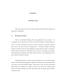
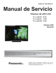
1.2
Basis Of Project
The idea of this project is to have a transmitter that will activate the PIC that
already attached with the GPS module. The information gathered and will be sent via
SMS to the other person.
Figure 1.1: Basic Block Diagram of the Emergency Notification System
1.3
Problem Statement
Nowadays, many cases of snatch theft occurred in our country and it becomes
the serious issues. There are lots of articles in the newspapers and on the internet to
show the seriousness of the offence of snatch theft. On January 30th 2005, our nation's
leading newspapers, namely Berita Minggu and The Star had reported snatch theft
crimes, which had happened near Ipoh, Perak. The suspect had snatched the bag from a
sixty year old woman at a shopping mall at Jalan Kampar, as the woman was walking to
her car. The twenty years old thief, who had tried to escape in his car, also knocked
down a man, who suffered minor injuries. The suspect ran through the traffic lights and
collided with two cars. This has caused him to lose control of his vehicle, which then hit
the road sign. The suspect then was detained [17].
According to the statistic of the theft in Malaysia, snatch theft has recorded the
third highest of the theft cases in Malaysia. It has been recorded from year 2000 until
year 2006. The snatch theft were seeing drop since year 2003, from 15798 cases to 9551
3
cases in 2006, or equivalent to a drop of 39.5% [15]. Because of that situation, it is
necessary to develop a system that can alert someone about the snatch theft incident by
sending a short message (SMS) by pressing one button.
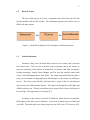
Figure 1.2: System Diagram
1.4
Objective
The objective of this project is to design an alert system which can send a short
message (SMS) about an emergency that had occurred. Referred to the figure 1.2 above,
the detector is an emergency button (Tx) consist of transmitter and receiver (transceiver)
which will activate the GSM based device and send emergency message that already
programmed in the PIC. That person does not have to type any words, but just press the
button and the message will be sent automatically.
4
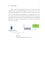
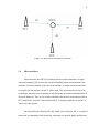
1.5
Scope of Study
Figure 1.2 shows the block diagram for the system. It consists of four main
components which are GPS module, transmitter and receiver (Rx and Tx), PIC
microcontroller and GSM mobile. The transmitter (Tx) will be hold by the person that
will be used to press the button when emergency occur. The signal will receive by the
receiver (Rx) and it will be activated the PIC microcontroller. The PIC stores the data
from GPS module and the transceiver. The data will be sent to the user via SMS using
GSM mobile. The distance for emergency button (Tx) and Rx are limited less than
100m if it is in line of sight.
Figure 1.3: Distance between Tx and Rx
CHAPTER 2
LITERATURE REVIEW
Literature review consists of previous related to the project, information, articles
and theories that make up the whole project. This chapter highlights the basic concepts
and the fundamental theories of the part that will be used in the project. The parts
discussed in the project are GSM mobile, GPS module, PIC microcontroller and mobile
phone.
Besides that, this chapter will also explain the universal asynchronous receiver
transmitter (UART) which is used at to connect the GPS and GSM, MAX232 and
microC Pro.
2.1
Related Works
There are several studies have been done before to develop similar emergency
system project. These previous projects can be used as references to develop
methodology and instruments used with some modification.
The first project is from Khafidha Binti Adi Azahar [4] who designed RFID
tagged services using GPS and SMS for tracking purposes. This project focused on
tracking the packages brought by the delivery lorry.
To make that possible, each
package was tagged by RFID electronic tag. She used passive RFID instead of bar code
6
because RFID electronic tags do not require a visual scan and can carry significantly
more information. Bar coding is almost everywhere these days, but it requires a close
and accurate visual scan by a bar code reader. RFID tags on the other hand require only
that the package be within radio frequency range of the RFID receiver or RFID
interrogator.
The other previous work that is related to this project is Smart Vehicle Data
Logger Using GPS and GSM. This project has been done by Wan Mohd Amir Haris Bin
Wan Sallehuddin. The objective of this project is to store the data that from GPS to the
memory card [2].
Next the commercial product that already widely used is panic alarm. Panic
alarm is an electronic device designed to assist in alerting somebody in the emergency
situations where a threat to persons or property exists. Normally panic alarm will used
in critical system such as a nuclear weapon system. It is used to quickly activate an
extreme measure to mitigate an emergency situation. Panic alarm has a unique system.
This system can be used with elderly and vulnerable family member. The system will
dial out up to 3 programmed telephone contact after a button is pressed [2]. Refer to
appendix A for complete user manual of the panic alarm.
7
Figure 2.1: Phone Dialing Panic Alarm [16]
2.2
GSM Modem
Figure 2.2: GSM Modem
8
GSM stands for Global System for Mobile Communications and is the most
popular mobile phone standards commonly used in the world [13]. Normally GSM
modem has built in antenna and has a slot. The function of that slot is to insert the SIM
card. This SIM card is used to get the signal from telecommunication provider such as
Celcom, Maxis and Digi. GSM modem also can be found in the mobile phones as long
as the mobile phone is using GSM and not CDMA.
The GSM Modem terminal uses a specific programming language, or a set of
commands called AT Commands, from the HAYES AT commands, created by Dennis
Hayes[7]. AT stands for attention which means the commands will attract the modem’s
attention. Besides modem mobile, HyperTerminal also use the AT command.
There are a lot of AT commands that can be used to for the GSM modem. But
for this project, the commands that will be used are only focus on sending and receiving
text message only. The software that will be used to implement the AT commands is
PIC Basic Pro. The table below shows several of the AT command.
Table 2.1: Examples of the AT command for SMS
GSM function can also be obtained from mobile phone. It is because mobile
phone is one of the GSM devices. But to make it function as GSM modem, it needs a lot
of modification. Therefore, the used of GSM modem are more preferred.
9
There are some benefits of using this GSM modem such as:
i.
GSM modem are low cost compared to mobile phone
ii.
Easier to operate without doing any modification
iii.
It is compact and have a nice look with the silver casing
iv.
Easier to interface with the PIC
v.
Have its standard power adapter with the standard power supply and come up
with the modem cable.
2.3
Global Position System (GPS) Module
The Global Positioning System (GPS) is a satellite-based navigation system
made up of a network of 24 satellites placed into orbit by the U.S. Department of
Defense. GPS was originally intended for military applications, but in the 1980s, the
government made the system available for civilian use. GPS works in any weather
conditions, anywhere in the world, 24 hours a day [12]. To get the accurate longitude
and latitude, the GPS receiver or also known as GPS modules in this project will use the
concept of triangle to determine the exact location of the user or anything that attach to
the GPS module.
The concept is called triangle concept because a GPS receiver must be locked on
the signal of at least three satellites. So that the satellite can calculate the position of the
GPS receiver in 2D position accurately. Normally the GPS used to monitor the motion
of transports are in 3D view. To get that view, it must use at least four satellites. The
function of GPS not limited to only calculate the position of the GPS receiver, it also can
determine the speed, track, trip distance, distance to the destination, the shortest distance
to the destination, sunrise and sunset time.
10
GPS also widely used in fleet system. It is a brilliant solution in order to increase
the efficiency of the management of group of vehicle. [12] To build this system, digital
maps, mobile communications and embedded system are combined in one system. This
system has three parts which is localization and position module, communication
module and CPU module.
Figure 2.3: GPS module
11
Figure 2.4: Basic Idea Calculation for Position
2.4
Microcontrollers
Microcontroller unit (MCU) or famously knows as microcontroller is a single
chip microcomputer [10] are more used in the controlling system and animation of the
machines. It does not depend on the size of the machine, as long as the microcontroller
are suitable for that machine, the MCU will be used. This microcontroller is one of the
technologies that have been developing to help the human to continue miniaturization of
electronic hardware. There is a lot of microcontroller that has their own function such as
PIC, Atmel AVR, Freescale Colfire and Intel 8051. Normally people like to use PIC or
Atmel to do their project.
The main difference between PIC and Atmel is their function. PIC is to reduced
instruction set computing which means the instruction can provide higher performance.
12
But for the Atmel it is complex instruction set computer based. Meaning that, a single
instruction can execute several low level operations.
Besides that, PIC and Atmel comes from different manufacturer. For this project,
using PIC is more suitable because PIC have built in analog to digital converter (ADC).
This ADC is important for communication port because signal received normally in
analog.
2.4.1
PIC microcontroller
PIC or peripheral Interface Controller is a type of microcontroller, product from
Microchip technology. PIC is suitable used in wide range and have a lot of attractive
features [10]. PIC has its own family that is define according to the pin. For examples is
PIC 16 family, PIC 18 family and PIC 30 family. It also differentiates the maximum
speed of the PIC, program memory size, maximum clock speed and the availability.
13
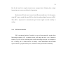
2.4.2
PIC16f877A
Figure 2.5: PIC16f877A
The pin instruction already attach at the Appendix C
The PIC16f877A contains of 8k Read Only Memory (ROM). This PIC can be
program using pin PGM, PGC and PGD [8]. The number of instruction has been limited
to 35 in the mid-range PIC. Therefore, it has been classified as reduce instruction set
computer (RISC).
When the power down, the data will be stored in nonvolatile user memories
block in the PIC MCU. For example, the data for secure code for smart card reader of
code for an electronic. The PIC16F877A has 256 bytes for a block which is typical
value.
14
2.4.3
Universal Asynchronous Receiver Transmitter (UART)
UART is a communication port that built in the PIC. Normally UART will use
max232 connection. Besides UART, there is another communication port that has
similar function like UART which is USART. USART stand for Universal
Synchronous/Asynchronous Receiver Transmitter. This serial connection are useful
because it only use one or two wire that carries signal for a parallel bus plus control
compared with another serial that used at least eight data lines. This USART connection
only needs three wires which is data send, data received and ground wire. So there is no
separated clock signal is needed. Because of that, it is called asynchronous [3].
Not all the PIC will come up with UASRT or UART port. Because of that, using
some simple programming, we can define any input output pin to be UART port. It is
called software UART.
2.4.4
MAX232
MAX232 is widely used in order to convert signal from serial port to a signal
that suitable use in TTL (transistor- transistor logic). MAX232 normally use in portable
computers, mow power modems, interface translation and multidrop RS-232 network.
MAX232 use no external component. That is why it is recommended where the space is
limited in printed circuit board (PCB).
MAX232 used output voltage +5V and is required some external capacitor which
are 1uF. The functions of the capacitor that attach to the MAX232 are as protection
device. Besides that, capacitor also used to stabilize the input voltage.
15
When a MAX232 IC receives a TTL signal, it will convert the signal to the
positive and negative value such as when the logic is 0, the TTL change the voltage from
+3 to +15V and when the logic is 1, and the output voltage is -3 to -15V.
Figure 2.6: Pins Configuration and Typical Operation Circuit for MAX232
16
2.5
Software Development
There is a lot of software that can be used to program the PIC. For examples are
MPLAB IDE and MicroC Pro. These two programs are basically used to program the
PIC and also change the command into the Hex format.
2.5.1
MicroC Pro
MicroC Pro is one of the product produce by Microchip. It is a full- featured
ANSI C compiler for PIC and a best solution to develop coding for the PIC. It provides
examples along with tutorial, thus learning the coding process becomes easier.
Compared to the MPLAB, the coding quit lent because of all the parameters must be
defined first. But the MicroC Pro is simpler. The programming process not only easy,
but it has shorter coding which have the same function as the command in the MPLAB
[].
The main function of the designing the MicroC Pro is to provide the programmer
with the easiest possible solution in order to develop applications for embedded system.
Besides that, the performance of the system also maintained while using this software.
There are a lot of improvements have been done in the IDE for MicoC Pro. Some
changes have done to make this software more compatible compared to IDE MPLAB.
For example, this software have fixed the error in Code explore. Normally code explorer
will define error if there are no brackets “()” put after void command, but with this
MicroC Pro, there is no error if there are no brackets.
17
Figure 2.7: MikroC PRO for PIC IDE
2.6
Radio Frequency (RF) Transmission
The distance may be short (remote control) or long (normally radio
communication that involve thousand kilometers). The range for radio frequency is from
a few ten hertz until gigahertz.
18
Figure 2.8: Frequency Band
From the figure above, the radio frequency starts from 100MHz until 10GHz.
That frequency are standardize to the entire world. The frequency above is also known
as ISM (industrial, scientific and medical) band. This frequency is standardizing by ITUR. ITU-R is one of the sectors in International Telecommunication Union.
CHAPTER 3
METHODOLOGY
This chapter explains more on procedures and process of the overall project
that’s related to the objective of the project.
3.1
Problem Identification and Analysis
Before the project can be started, the first thing that needs to do is to identify
and analysis the problem exist. Problem identification may refer to the challenges or
problems which will be faced while doing the project, and may affect objectives of the
project. After deciding the suitable title for the project, I have to analyze whether this
project can help the community or not.
Besides that, I have to understand the
importance of integrating the whole system, so that, the objective of this project can be
achieved.
3.2
Preliminary Research
Preliminary research is the important part of this project. Preliminary research
can also be called as the backbone of the project. Extensive researches related to this
project are needed to gain sufficient knowledge and strong understanding about the
project. Preliminary research is ongoing and done in every stages of developing this
project.
20
The first stage of the research includes the finding on the information needed so
that the objective can be achieved. Besides that, the research also covers the literature
review from journals, books, and internet that will support to understand more on this
project especially the information about the GPS, modem mobile and PIC
microcontroller.
3.3
Components and Tools Identification
The main component to build up the system of this project are GPS module that
act as GPS receiver, modem mobile, mobile phone that will receive all the information
sent and PIC microcontroller that will process all the gathered information.
3.3.1
Protoboard
Protoboard or also known as breadboard is a board that normally used in the
electronic first design circuit. The construction of the breadboard is based for
prototyping of the electronic. Solder less breadboard is the term that normally used to be
referred to this breadboard. For this project, the circuit is being tested using breadboard
and after the entire components are working well, the circuit is fabricated.
21
Figure 3.1: Breadboard
Tx
Rx
Antenna
Figure 3.2: Breadboard with Completed Transmitter and Receiver Circuit
22
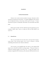
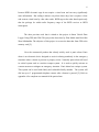
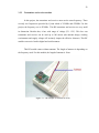
3.3.2
Transmitter and receiver module
In this project, the transmitter and receiver must use the same frequency. There
are only two frequencies provided by Cytron which is 315MHz and 433MHz. For this
project, the frequency use is 433MHz. This RF transmitter and receiver are very small
in dimension. Besides that, it has wide range of voltage (3V- 12V). This low cost
transmitter and receiver can be used up to 100 meters (the antenna design, working
environment and supply voltage will seriously impact the effective distance). This RF
module can receive both in digital and serial manners.
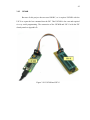
This RF module comes without antenna. The length of antenna is depending on
the frequency used. For this module, the length of antenna is 18cm.
Figure 3.3: The Length of Antenna Is 18cm
23
Figure 3.4: Transmitter Module 433 MHz
Table 3.1: Description Transmitter Pin
Label
Description
Data
The Data pin of the transmitter
VCC
The power supply of the transmitter
GND
The ground of the transmitter
ANT
The hole to solder and connect antenna)
24
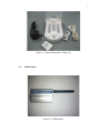
Figure 3.5: Receiver module 433MHz
Table 3.2: Description Receiver Pin
Label
Description
Data
The data pin of the receiver
VCC
The power supply(5v) to the receiver
GND
The ground of the receiver. (2 GDN are internally connected each other)
ANT
The hole to solder and connect antenna)
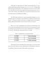
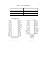
3.3.3
Decoder and encoder
This pair of transmitter and receiver comes with pair of decoder which is PT2262
for transmitter module and PT2272-L4 for receiver module. This decoder also has its
own value of resistor that act as oscillator.
25
Table 3.3: Value of Oscillator Resistor
PT2262
PT2272
4.7MΩ
820KΩ *
3.3MΩ
680KΩ *
1.2MΩ
200KΩ **
Figure 3.6: Pin of the Decode
Figure 3.7: Pin of Encoder
26
Figure 3.8: Block Diagram for Decoder PT2272
27
Figure 3.9: Flow Chart Diagram for PT2272
Flow chart in figure 3.8 explains about how the decoder PT2272 operates. First,
when the power is ON, the decoder is in standby mode. After PT2272 received input 1,
it will enable the transmission of the data. But, if the decoder does not received input 1,
it will maintain in the standby mode. After the transmission is enabled, the data from the
input port will be sent. These steps will continue as long as the transmission port is
enabled.
28
Figure 3.10: Block Diagram for Encoder PT2262
29
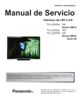
Figure 3.11: Flow Chart Diagram for PT2262
Figure 3.10 above describes the operation of the encoder PT2262. The first step
is similar to the decoder PT2272 which is in standby mode if there is power supply
connected to it. Then this encoder will wait the signal from decoder PT2272. If there is
no signal coming in, it will continue in standby mode. After the encoder received the
signal from decoder PT2272, it will read the address sending in. if the address received
30
is different, it will disable the VT (valid transmission). Then, the encoder will enter in
the standby mode again. After the address receives is match with the encoder’s address,
it will enable the VT. The process of matching the address will continue until all bits are
correctly sent.
After all the specification is chosen, the transmitter and receiver circuit can be
design and constructed.
Figure 3.12: Schematic Diagram for Transmitter and Receiver
31
3.3.4
Testing result for transmitter and receiver circuit.
Even though this project only use this transmitter and receiver circuit just to
trigger the PIC, but it is still need to be tested so that we know this circuit are
functioning well and can be act as wireless switch [1]. It is also known as remote.
Table 3.4: Testing Result
TRANSMITTER
RECCEIVER
S0
S1
S2
D0
D1
D2
0
0
1
0
0
1
0
1
0
0
1
0
0
1
1
0
1
1
1
0
0
1
0
0
1
0
1
1
0
1
1
1
0
1
1
0
1
1
1
1
1
1
From the result above, it can say that, this transmitter and receiver circuit is
working well. But for this project, we want to use only one output that can trigger the
PIC to send the message. So we set S0 is high and the rest are low. Then, the D0 are
connected to one of the I/O pin of the PIC.
3.3.5
Power Supply
To make the PIC function very well, it requires a suitable power source. Because
of that, a power supply that has output voltage 5V is used in this project. The power
supply is one type of the step down transformer. In this project the AC voltage are being
step down to 5V DC voltage. If there is no power supply that can gives the output 5V,
32
we also can use 12V DC or 9V DC, but it required voltage regulator 5V to step down the
voltage until 5V.
Figure 3.13: AC to DC Power Supply
3.4
GSM Modem
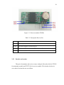
3.4.1
GSM Modem interface Description
1. This GSM has one serial port that used 3.3V TTL voltage level/ RS232 Voltage
level optional with the bit rate 115200bps
33
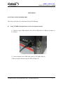
2. The power supply for this GSM modem is 7.5V with 500mA using direct current
(DC)
3. It has antenna interface so that it can received from the mobile station
4. It has a status light that indicates the power status. The red light will appear when
the power is ON
5. It is come up with SIM card holder.
6. For the installation and checking the GSM modem, refer to the appendix A [5]
Figure 3.14: GSM Interface [6]
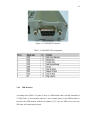
3.4.2
GSM RS-232 Interface
Figure 2.4 below shows the interface of RS 232 (D-SUB 9-pin female) of the
GSM modem.
34
Figure 3.15: GSM RS232 interface
Table 3.5: GSM RS232 Pin Assignment
3.4.3
SIM Interface
According to the GSM 11.12 phase 2, there is a SIM interface that’s already intended for
3V SIM cards. A wire interface which is 5 wires already places in the GSM modem to
interface the GSM modem with the card holder [3]. To put the SIM card or eject the
SIM card, the button must be push.
35
Figure 3.16: SIM Interface
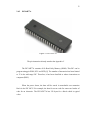
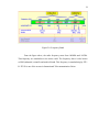
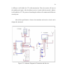
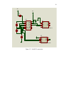
3.5
MAX232
In this project, MAX 232 is required to convert the signal from RS232 port of
GSM modem and GPS module to the signal that the PIC can read. The diagram below
shows the schematic diagram for connection between MAX232, GPS module and GSM
modem.
36
VDD
VDD
C2
1u
1
2
3
4
5
C1
1u
7
8
C3
U3
C1+
VCC
V+
GND
C1T1OUT
C2+
R1IN
C2R1OUT
VT1IN
T2OUT T2IN
R2IN R2OUT
MAX232
U1
16
15
14
13
12
11
10
9
5
4
3
2
1
GND
DTR
RXD
RXD
DCD
RI
CTS
RTS
DSR
9
8
7
6
MALE DB9 PORT FOR GPS MODULE
1u
U2
C4
1u
5
4
3
2
1
GND
DTR
RXD
RXD
DCD
RI
CTS
RTS
DSR
9
8
7
6
MALE DB9 PORT FOR GSM MODEM
Figure 3.17: MAX232 connection
37
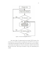
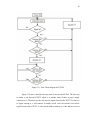
3.6
Flow Chart
Figure 3.18: Methodology of Project
38
Figure 3.11 above shows the flowchart of the methodology to conduct the
project. The first step is doing the search and study about the previous project or any
other articles, relevant paper and publication that related to this project. This project can
be divided into two parts which is software part and hardware part.
For the hardware part, it is important to know what types of components those
want to be used in this project. For example is PIC microcontroller. Microcontroller is
the most important part that will act like a brain of this system. It will control the system
according to the program that already stored to it. While the software part are more on
program the PIC by using C language. C language is the best in term of performance
when compared with Java or other language. Besides that, the C language is not too
difficult to learn in comparison to Java.
Next, the system must be tested after hardware part is done. If the system does
not work, the system must be troubleshooted and the problem identified. The process
will be repeated until the project is successful.
3.7
Gantt Chart
Gantt chart has been done to plan the process of this project. It is important to
make sure the project can be done at the given time.
39
Table 3.6: Gantt chart for FYP -1
Table 3.7: Gantt chart for FYP -2
40
3.8
Expected problem
After doing some literature study, expected problem have been identified such as
the limitation in distance and the size of the device. This is important to make sure that
the project can be done smoothly without any difficulty because of minor or major
problem.
In this project, the major problem is the limitation of the distance between the
emergency button and the receiver (Rx) that attach with the PIC. The signal can be
received by the RX if the distance between Rx and Tx are about 100m or less. The
maximum distance that these devices can operate is 100m if the RX and Tx are in line of
sight.
The second problem is the prepaid of the SIM card. Because of this project use
the existing telecommunication provider such as Celcom, Maxis and Digi, the SIM card
must have credit. So that, the message that already program in the PIC can be sent to
the person though modem mobile.
Next is the size of transmitter. Because of the transmitter is always carried by
person, so the size must as small as possible, so that, there is no one can know the
location of the transmitter.
41
3.9
Software Development
3.9.1
MicroC Pro
The program for this project has been done using MicoC Pro. As said earlier,
using MicroC Pro are more easily compared with MPLAB. Besides that, the program is
also quite short.
Figure 3.19: Coding using MicroC Pro
42
3.9.2
UIC00B
Because of this project does not used SK40C, so it requires UIC00B with the
UIC-S to export the hex command into the PIC. This UIC00B is low cost and required
six way serial programming. The connection of the UIC00B and UIC-S with the PIC
already attach at Appendix D
Figure 3.20: UIC00B and UIC-S
43
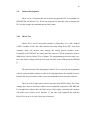
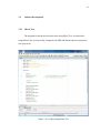
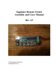
3.9.3
X-CTU
X-CTU is software provide by Digi. It is a windows- based application. This
software has been design to test the RF product from Digi. Because of my project also
used RF to send the data, so it is suitable for me to test the circuit and also the operation
in the PIC using X-CTU. X-CTU can either download from Digi’s web site or from the
installation CD.
Figure 3.21: X-CTU Configuration
From the figure above, there are two colors which are blue and red. Blue colors
the data types from computer and directed out to the communication port (UART port).
Next is the red color. The red color means the incoming data from communication port
of the PIC to the RS232 connection. Normally to do this testing, it requires DB9
connection or commonly known as RS232.
CHAPTER 4
RESULTS AND DISCUSION
In this chapter, the circuit design is being tested and the failure of the circuit is
being troubleshooted. The steps for the testing are shown in this part.
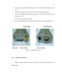
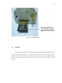
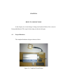
4.1
Project Hardware
The completed hardware design is shown as below.
Figure 4.1: Completed Circuit Design
45
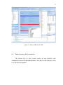
4.2
Project Test on Software
Before the project is being fabricated, the prototype of the project is tested. The
program of the PIC is tested using X-CTU. This is the example just to send “Hello” to
the number “+60139153008”.
Figure 4.2: PIC Test
46
This result shows all the connections for the circuit to the PIC are connected
well. If the components are not connected well, there is no “Hello” message display or
there is wrong mobile phone number.
Figure 4.3: Testing For Sending Actual Message
47
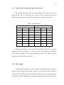
4.3
Project Test on Prototype board
After the test is done using X-CTU, the GSM modem is connected to the
protoboard. If the connection for the GSM modem is correct, the message can be sent to
the mobile phone.
Figure 4.4: Reset the Circuit
48
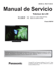
I’m in danger
Figure 4.5: Message Has Been Sent To Mobile Phone
From the figure 4.5, we can say that this project is able to send the
emergency message to the mobile phone with only one button is pressed. But there is no
message for location such as longitude and latitude are being sent.
CHAPTER 5
CONCLUSION AND RECOMMENDATIONS
5.1
Introduction of Conclusion
The aim of this project is to send the SOS message that can alert the receiver
about the danger. For the conclusion, this project has been successfully designed and
tested. The message can be sent to the user when the button is pressed. The system needs
to create the interface between receiver 433MHz, GSM modem and GPS module. This
entire element is being controlled by microcontroller that will act as the brain of this
project. The microcontroller will control the message sending when receives the signal
from receiver 433MHz.
For longitude and latitude, this design is not completed yet because the system is
unable to send the message with the data that already read by the GPS. It is because
there are some errors in the programing related to the GPS module. But the system still
can send the message “i’m in danger”.
5.2
Project limitation recommendation
This project has several limitations that can be improved. For example is the
distance between transmitter 433MHz to the receiver 433MHz. As mentioned in the
50
scope of study, the distance is limited until 100m only. Further than that, the signal does
not reach the receiver. To overcome this problem, we need to change the transmitter and
receiver. Besides that, we can also change the antenna. Instead of using copper wire as
the antenna, we can change it using high gain antenna. Next the other suggestion to
increase the length is replace the transmitter with the GSM. The coverage of the GSM is
same with the module phone, so it is suitable for the long distance.
Next is about the data received from the GPS module. The data that received
from the GPS such as longitude and latitude is not 100% correct. There is still minor
error in calculating the distance and location by the satellite. But it is still can be used
because the range are below than 1km square of area. To overcome this problem, the
GPS module that is used must have high sensitivity. So that, it can measures the location
correctly.
Then, it is about GSM module. This GSM module uses SIM card to operate. The
SIM card can be obtained from the provider such as Celcom, Maxis of Digi. For this
project, I use SIM card from Celcom. The main problem is the balance credit in the SIM
card. So, when dealing with this system, the credit left must always be checked, so that
the system can run properly. Besides that, using the different provider also make the
system fail to send the message. Even though it is only simple modification in the
programming, but it will give major impact to the system.
51
References
1. Murniwati Bt Anwar, “Wireless Notification System For The Hearing Impaired”,
Master of Engineering (Electrical – Mechatronic & Automatic Control),
Universiti Teknologi Malaysia, 2007.
2.
MicroC PRO for PIC Help “Introduction to mikroC”, version 4.60, 2002-2011
3. Wan Mohd Amir Haris Bin Wan Sallehuddin “Smart Vehicle Data Logger Using
Global Positioning System And Global System For Mobile Communication”,
Bachelor of Degree, Universiti Malaysia Pahang, 2008
4. Khafidha binti Adi Azahar, “RFID tagged courier services using GPS and SMS
for tracking purposes”, Bachelor of Degree, University Technology Malaysia,
2008.
5. Martin P. Bates, “programming 8-bit PIC Microcontrollers in C with interactive
Hardware Simulation”, Elsevier Ltd, USA, 2008.
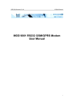
6. “MOD 9001D RS232 GSM/GPRS Modem User Manual”, (2007) Sky
Microwave Co. Ltd
7. “SIM300 AT Commands Set”, SIMCOM Limited,2008
8. Microchip Technology Inc, “PIC16F877A Data Sheet”, USA, 2003
9. M Popa, member IEEE, and B Suta “A Solution For Tracking A Fleet Of
Vehicles”, 2011
10. Avay V Deshmukh, “Microcontroller: Theory and Application”, Tata McGrawHill Publishing Company limited, New Delhi, 2007
11. W.M Fahmi Fathuddin bin Wan Mokhtar, “Smart Office Using RFID Via PIC
and PLC”, Universiti Teknologi Malaysia, 2009
12. Pratap Misra and Per Enge , “Global Positioning System: Signals,
Measurements, and Performance Second Edition” , 2006
13. Syazana Binti Mustafah “RFID Campus Security System Via GSM”, Bachelor of
Electrical Engineering (Mechatronics), University Technology of Malaysia, 2009
52
14. “Introduction to the Global Positioning System for GIS and TRAVERSE”, First
U.S. Publication in June, 1996, Corvallis Microtechnology, Inc.
15. SMALL – M, “Malaysia: Crime Statistic 2000-2006 (I)”, from
http://micpohling.wordpress.com/2007/05/30/malaysia-crime-statistic-20002006-i/ retrieve from Polis Diraja Malaysia website.
16. QUICKSAVE Security System, “Panic Alarms (Phone Dialling) with neck worn
panic pendant and panic button” from http://www.quicksafe.co.uk/phone-panicalarm.htm
17. Feisal Azmi (2005, December 09) “Criminal:Snatch Theft”, retrieved December
12, 2005 from http://legalstudy.blogspot.com/2005/12/criminal-snatchtheft.html
APPENDIX A
PANIC ALARM SYSTEM
DAS1100
Distress alertsystem
• Alerts friends
and family at the press of a button
• Allows independence while keeping you in touch
• Helps you maintain your active lifestyle
User Manual
Keep this manual safe for future reference
(2007) Sky Microwave Co.
All Rights
APPENDIX B
GSM MODEM
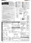
5. Installation
a) Open the SIM card holder, insert in a valid SIM Card provided by GSM network operator or
service provider.
b) Install the GSM Modem to your location and connect the antenna to the SMA connector.
c) Fix the serial cable to the GSM modem, the supplied cable will connect the unit to a PC. For
other devices you may need a crossover cable.
d) Connect the GSM Modem power supply interface with the power adapter’s output
jack, and then connect the adapter to its power supply source.
Make sure that all connections are properly
(2007) Sky Microwave Co.
All Rights
6. Modem Basic Operation
A. Module connection with Hyper Terminal.
1. Establish or Open Hyper Terminal from All Programs Æ
Accessories-
Æ Communications and setting up relevant parameters. Module baud rate is
115200. (1). Establish connection.
(2). Setting up usage port.
(2007) Sky Microwave Co.
(3). Setting up port parameters.
(4). Setting up property in File Menu of Hyper Terminal
All Rights
(2007) Sky Microwave Co.
All Rights
2. You can input word “AT” then press “Enter” key, it should be response word “OK” means
work property. All commands are executed by pressing “Enter” key.
Example as below:
(2007) Sky Microwave Co.
All Rights
3. If SIM card requires switch on password, please enter: AT+CPIN=“password”
4. Read module information
AT+CGMI (Manufacture name
) AT+CGMM (Read Module
model)
AT+CGMR (Read module current SW version information)
AT+CGSN (Module serial number)
B. Dial call or receive call (Modem doesn’t provide voice port even with
relevant command)
1. Dial call ATDxxxxxxxxx; (xxxxxxxxx is phone number,example:ATD1860;)
2. Call waiting function:AT+CCWA
3. Hold function:AT+CHLD=?
4. Dial latest call number:AT+CLCC=?
5. Enter information once connection established(DTMF):AT+VTS=(0-9,#,*,A-Z)
Dial Extension number(example:1234):AT+VTS=1
AT+V
TS=2
AT+V
ST=3
AT+V
ST=4
6. Receive call: ATA
7. Hang off call: ATH
8. Incoming call ID: AT+CLIP=1
9、SMS function:
⑴ Setting up SMS Center number:AT+CSCA=“+8613800XXXXXX”,145
SMS Center number:+8613800XXXXXX
⑵ TEXT parameter:AT+CSMP=17,168,0,0 English format
AT+CSMP=17,168,0,0 Chinese format
⑶ Send SMS:AT+CMGS
⑷ Read single SMS:AT+CMGR=1
⑸ List multiple SMS:AT+CMGF=1
AT+CM
GF=4
(2007) Sky Microwave Co.
⑹ Delete SMS:AT+CMGD
Example 1:Send English character SMS
AT+CMGF=1
AT+CSMP=17,168,0,0
AT+CMGS=“Telephone number”
>Character information Ctrl+z
Example 2:Send Chinese character SMS
AT+CMGF=1
AT+CSMP=17,168,0,8
AT+CMGS=“Telephone number”
>Chinese character information Ctrl+z
10. Chinese character information is Unicode.
All Rights
APPENDIX C
Pin Instruction and Internal Architecture for PIC16877A
ROBOT . HEAD to TOE
Product User’s Manual – UIC00B
APPENDIX D
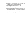
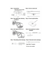
6. INSTALLATION (HARDWARE)
This section will show the connection during UIC00B usage.
6.1 Using UIC00B with application circuit (development board)
1. Connect A-type USB connector (one end of USB cable) to USB port at laptop or
PC desktop.
2. Connect another end of USB cable (mini) to UIC00B USB port.
• Power supply indication green LED will light ON.
Created by Cytron Technologies Sdn. Bhd. – All Rights Reserved
9
ROBOT . HEAD to TOE
Product User’s Manual – UIC00B
3. Continue to software installation if this is the first time usage. Refer to section 6
for software installation guide.
4. Connect one side of programming cable to box header of UIC00B and the
other side to box header of development board (target device) to be program.
• Use external power for the target board, UIC00B cannot support large
power usage.
Created by Cytron Technologies Sdn. Bhd. – All Rights Reserved
1
0
ROBOT . HEAD to TOE
Product User’s Manual – UIC00B
6.2 Using UIC00B with UIC-S (optional, buy separately)
1. Connect A-type USB connector (one end of USB cable) to USB port at laptop or
PC desktop.
2. Connect another end of USB cable (mini) to UIC00B USB port.
• Power supply indication green LED will light ON.
3. Continue to software installation if this is the first time usage. Refer to section 6
for software installation guide.
4. Connect one side of programming cable to box header of UIC00B and the other
side to box header of UIC-S board.
• No external power required for UIC-S to function.
Created by Cytron Technologies Sdn. Bhd. – All Rights Reserved
11
ROBOT . HEAD to TOE
Product User’s Manual – UIC00B
UIC-S
UIC00B
Created by Cytron Technologies Sdn. Bhd. – All Rights Reserved
12
ROBOT . HEAD to TOE
Product User’s Manual – UIC00B
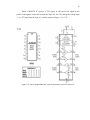
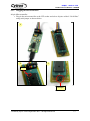
6.2.1 Plugging the microcontroller
40-pin Microcontroller
• Plug in the microcontroller at the ZIF socket and select 40 pins at label “28/40 Pins”
using mini jumper as shown below.
1
2
3
Pin 1
Select to
28/40 pins
Created by Cytron Technologies Sdn. Bhd. – All Rights Reserved
13
ROBOT . HEAD to TOE
Product User’s Manual – UIC00B
28-pin Microcontroller
• Plug in the microcontroller at the upper portion of the ZIF socket and select 28 pins at
label “28/40 Pins” using mini jumper as shown below.
1
3
2
Pin 1
Select to
28/40 pins
Created by Cytron Technologies Sdn. Bhd. – All Rights Reserved
14
ROBOT . HEAD to TOE
Product User’s Manual – UIC00B
18-pin Microcontroller
• Plug in the microcontroller at the lower portion of the ZIF socket and select 18 pins at
label “18 Pins” using mini jumper as shown below.
1
2
3
Pin 1
Select to 18
pins
Created by Cytron Technologies Sdn. Bhd. – All Rights Reserved
15