1
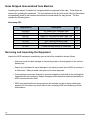
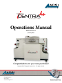
Operations Manual
Manual Version 2.2
January 2015
Congratulations on your new purchase!
Copyright Allen Datagraph Systems Inc. - All rights reserved.
01
02
Thank You for Selecting an Allen Datagraph Product
At Allen Datagraph Systems, Inc. (ADSI), we are committed to serving you, our customer. Our goal is
to provide you with competitive, quality products and services to meet your needs. Customer input is of
great value to Allen Datagraph Systems, Inc.; therefore, we encourage any comments or suggestions.
The instructions contained in this manual are intended to ensure the safe installation, operation,
and maintenance of your machine. Please read this manual carefully before performing any activity
on the equipment. Please note information contained in this manual does not modify or alter, in any
way, the standard terms, and conditions of your Allen Datagraph Systems, Inc. purchase contract.
This manual should be readily accessible to operating and maintenance personnel at all times.
Proper use of this manual, in addition to other Original Equipment Manufacturer’s manuals and your
in-house manuals, will assure safe, reliable and cost-effective performance of ADSI machinery.
If you are in need of service, please contact our Technical Support staff as instructed on the following
pages. In order to expedite your request please include the serial number of your machine. Each Allen
Datagraph Systems, Inc. machine has a label identifying its serial number.
General Information
Allen Datagraph Systems, Inc. (Hereafter known as ADSI) Operating Manuals and Addenda
provide a general understanding of the operation of the contracted system, its major components,
and the functional elements of those components.
The Manuals and Addenda contain Safety, Description, Installation, Operation, and Maintenance
information. We strongly recommend thoroughly reading and understanding the information in this
manual before operating this equipment. If additional information is required, or clarification needed,
feel free to contact ADSI.
The Manuals and Addenda may not be copied or reproduced, in whole or part, without written
consent of Allen Datagraph Systems, Inc
03
Disclaimer of Warranties and Limitation of Liabilities
ADSI Digital Printing Systems are warranted free of defects in both materials and workmanship.
Should any part of this equipment be defective, it will be repaired or replaced, at the option of the
manufacturer, at no charge for parts or factory labor for a period of one (1) year from the date of
installation. All warranty services are performed at the ADSI factory. Replacement parts not
installed at the factory will be billed to the customer at regular prices and credit will be issued when
the defective parts are returned. The customer is responsible for freight on warranty parts and
repairs.
This warranty is void if:
The equipment has been damaged by negligence, accident or mishandling, or has not been operated
in accordance with the procedures described in the operating instructions;
or:
The equipment has been altered or repaired by other than an approved service station or factory
service center, or adaptations or accessories have been attached to the equipment that shall have
adversely affected the performance, safety, or reliability of the equipment.
NO OTHER WARRANTY, EXPRESSED OR IMPLIED, APPLIES to the equipment. ADSI does not
assume any responsibility for consequential damages occasioned by the equipment, or inconvenience or interruption in operation.
In case of unsatisfactory operation, ADSI or its Dealer should be notified immediately.
Technical Support
Technical support is available during business hours based on Eastern Time Monday through
Friday 7:30 am to 4:30 pm.
For Technical support please access our free e-mail support or visit our web site at http://www.
allendatagraph.com, and then clicking on tech support and the email link.
Service Policy – All service is subject to ADSI service policy. You can read the policy here: Web
Site Copy - www.allendatagraph.com/wp-content/uploads/2014/01/ADSI-ServicePolicy.pdf
There are many online documents available to help you to operate the Centra HS at our technical
support page at http://www.allendatagraph.com. Mouse-over Tech Support then Online Documents,
and fill out the form.
04
Specifications
System Data:
Print Technology
Resolution
Speed
Web Width
Media Core
Max Input Roll Diameter
Cutter Management Tool
LED Toner
Up to 600 x 1200 dpi
Up to 30 ft/min (7.6 M/min)
8.5 to 12.9 inches (215-325 mm)
3 inches (75mm) nominal dia.
14 inches (355 mm)
Allen Direct-Cut
Network Connections:
Ethernet
USB
· 100BASE-TX
· 10BASE-T
High Speed 2.0
Power Requirements:
Centra HS Print Base & Printer: 720 watts voltage input ranges
100-132 VAC / 47-63 Hz or
180-240 VAC / 47-63 Hz
Dimensions and Weight:
Length
Width
Height
Weight
63 inches (160 cm)
26 inches (71 cm)
45 inches (44 cm)
200 Lbs (91 Kg)
05
Items Shipped Unassembled from Machine
A packing box marked “Accessories” is shipped with the equipment in the crate. These items are
required for operating the equipment. The tools included in this kit (such as the Hex Key Wrenches)
are specifically sized for the machine and should be stored nearby for easy access. The box
contains the following items:
Accessory Kit:
Component ID
Description
Qty
40239063
H05-353
H05-361
H05-360
DF-212
H21-010
H21-021
AC Power Cord, European Style
Ethernet Crossover Adapter
Black CAT 5E Ethernet Patch Cable, 14ft
USB Cable, 10ft Grey (A Male to B Male)
3/16” Hex Key Wrench (Long)
3/32” Hex Key Wrench (L Shape)
3.0 MM Hex Key Wrench (L Short Arm)
1
1
1
1
1
1
1
Receiving and Inspecting the Equipment
Inspect the ADSI equipment immediately upon arrival at the installation site as follows:
06
· Note any visual in-transit damage to the packing crate or the equipment on the carrier’s delivery slip.
· Report any concealed in-transit damage to the delivery carrier and to ADSI as soon as it is discovered. When possible, take pictures for claim purposes.
· Cross-reference amounts received to amounts shipped as indicated on the packing lists forwarded with the machinery. Report shortages and/or defective material immediately to ADSI customer service office.
· ADSI may require defective components to be returned in order to issue credit under warranty. Do not return any items without first contacting ADSI and obtaining a Return Authorization.
Table of Contents
1.0.0 Introduction . . . . . . . . . . . . . . . . . . . . . . . . . . . . . . . . . . . . . . . . . . . . . . . . . . . . . . . . . . . . . . 08
1.0.1 Safety . . . . . . . . . . . . . . . . . . . . . . . . . . . . . . . . . . . . . . . . . . . . . . . . . . . . . . . . . . . . . . . . . . . 08
1.0.2 Site Preparation . . . . . . . . . . . . . . . . . . . . . . . . . . . . . . . . . . . . . . . . . . . . . . . . . . . . . . . . . . 09
1.1.0 Installation of Centra HS Digital Label Print Station . . . . . . . . . . . . . . . . . . . . . . . . . . . . . . 11
1.1.1 Setup Printer Base . . . . . . . . . . . . . . . . . . . . . . . . . . . . . . . . . . . . . . . . . . . . . . . . . . . . . . . . . 11
1.1.2 Setup Printer . . . . . . . . . . . . . . . . . . . . . . . . . . . . . . . . . . . . . . . . . . . . . . . . . . . . . . . . . . . . . . 11
1.1.3 Set Printer on Printer Base . . . . . . . . . . . . . . . . . . . . . . . . . . . . . . . . . . . . . . . . . . . . . . . . . . . 11
1.1.4 Connecting the Printer Base to the Printer . . . . . . . . . . . . . . . . . . . . . . . . . . . . . . . . . . . . . . .11
1.1.5 Assembling the Printer . . . . . . . . . . . . . . . . . . . . . . . . . . . . . . . . . . . . . . . . . . . . . . . . . . . . . . 12
1.1.5.1 Accessing Printer . . . . . . . . . . . . . . . . . . . . . . . . . . . . . . . . . . . . . . . . . . . . . . . . . . . . . . . . . 12
1.1.5.2 Installing the Imagin Drums . . . . . . . . . . . . . . . . . . . . . . . . . . . . . . . . . . . . . . . . . . . . . . . . 12
1.1.5.3 Installing the Transfer Belt . . . . . . . . . . . . . . . . . . . . . . . . . . . . . . . . . . . . . . . . . . . . . . . . . . 13
1.1.5.4 Installing the Fuser . . . . . . . . . . . . . . . . . . . . . . . . . . . . . . . . . . . . . . . . . . . . . . . . . . . . . . . 13
1.1.6 Powering the Printer Base . . . . . . . . . . . . . . . . . . . . . . . . . . . . . . . . . . . . . . . . . . . . . . . . . . . 14
1.1.7 Connecting Printer Base to PC . . . . . . . . . . . . . . . . . . . . . . . . . . . . . . . . . . . . . . . . . . . . . . . 15
1.1.8 Printer Base Controls . . . . . . . . . . . . . . . . . . . . . . . . . . . . . . . . . . . . . . . . . . . . . . . . . . . . . . 15
1.1.9 Printer Driver . . . . . . . . . . . . . . . . . . . . . . . . . . . . . . . . . . . . . . . . . . . . . . . . . . . . . . . . . . . . . 15
1.2.0 Webbing the Roll Media and Test Print . . . . . . . . . . . . . . . . . . . . . . . . . . . . . . . . . . . . . . . . 16
1.2.1 Installing Wasatch SoftRIP . . . . . . . . . . . . . . . . . . . . . . . . . . . . . . . . . . . . . . . . . . . . . . . . . . 17
1.2.2 Setting up the Centra HS in Wasatch . . . . . . . . . . . . . . . . . . . . . . . . . . . . . . . . . . . . . . . 17
1.2.3 Wasatch Test Print . . . . . . . . . . . . . . . . . . . . . . . . . . . . . . . . . . . . . . . . . . . . . . . . . . . . . . . . 18
1.2.4 Printing a Job from Wasatch . . . . . . . . . . . . . . . . . . . . . . . . . . . . . . . . . . . . . . . . . . . . . . . . 18
1.3.0 Cleaning the Printer . . . . . . . . . . . . . . . . . . . . . . . . . . . . . . . . . . . . . . . . . . . . . . . . . . . . . . . . 20
1.3.1 Cleaning the LED Lens Array . . . . . . . . . . . . . . . . . . . . . . . . . . . . . . . . . . . . . . . . . . . . . . . . . 21
1.3.2 Cleaning the Imaging Drums . . . . . . . . . . . . . . . . . . . . . . . . . . . . . . . . . . . . . . . . . . . . . . . . . 21
1.4.0 Troubleshooting & FAQ . . . . . . . . . . . . . . . . . . . . . . . . . . . . . . . . . . . . . . . . . . . . . . . . . . . . . 22
1.4.1 Material Compatibility . . . . . . . . . . . . . . . . . . . . . . . . . . . . . . . . . . . . . . . . . . . . . . . . . . . . . . . 22
1.4.2 Material Test Procedure . . . . . . . . . . . . . . . . . . . . . . . . . . . . . . . . . . . . . . . . . . . . . . . . . . . . . 22
1.4.3 Media Weight Settings . . . . . . . . . . . . . . . . . . . . . . . . . . . . . . . . . . . . . . . . . . . . . . . . . . . . . . 23
1.4.4 Troubleshooting with Media Weight Settings . . . . . . . . . . . . . . . . . . . . . . . . . . . . . . . . . . . . . 24
1.4.5 Exit Speed Settings . . . . . . . . . . . . . . . . . . . . . . . . . . . . . . . . . . . . . . . . . . . . . . . . . . . . . . . . 24
1.4.6 Troubleshooting with Exit Speed Settings . . . . . . . . . . . . . . . . . . . . . . . . . . . . . . . . . . . . . . . 24
07
1.0 Introduction
The Centra HS Digital Label Printing System is shipped assembled, however it must be properly
unpacked, installed, and set up to run prior to operating. This manual will guide you through each of
these processes.
1.0.1 Safety
For your own safety, read this instruction manual before operating the equipment.
Knowledge of the machine’s components and specific hazards will minimize the possibility of
accidents and injury.
Wear proper clothing. Do not wear loose clothing, neckties, necklaces, or jewelry, which may be
caught in moving parts. Shoulder length hair and longer should be pulled back, and secured at all
times to prevent entanglement in equipment.
Keep your work area clean and well lit to prevent tripping or accidentally placing body parts in danger.
An Emergency Stop (E-Stop) push button located on the front of the machine near the cutter. Do
not use the E-stop to power off equipment unless there is an emergency. NOTE: The E-Stop only
powers off the systems printer base of the equipment. It does not power off the printer.
08
1.0.2 Site Preparation
The following are guidelines for preparing the customer site for installation of the ADSI equipment.
Location:
1. Provide a sturdy level area for equipment weighing 200+ lbs.
3. Ensure there is an appropriate power source and ethernet connection nearby.
2. Provide adequate clearance around the machine to allow easy access for inspection and maintenance.
Power Requirements:
Use of a HIGH QUALITY surge protector or uninterruptible power supply is REQUIRED by ADSI.
Failure to do so could affect your warranty coverage if a problem arises due to improper power
connection!
Risk of Electric Shock - The power cord is a three-conductor cable that uses a safety (earth) ground connection. The power cord must be plugged into an outlet that has an earth ground contact. NEVER plug the power cord into a two-prong outlet by using a 3=2 cord adapter.
Risk of Electrical Fire - NEVER allow roll or sheet goods to rub on the power cord as the material may damage the cord causing an electrical fire hazard!
Power Configuration:
ADSI products are factory preset for the power requirements of the destination country. The machine
configuration is indicated on the power input module as either 115V or 230V.
Changing the Fuse Configuration:
1. Disconnect the AC power cord from the fuse block on the power input end panel.
2. Open the fuse block cover with a small flat screwdriver and pull out the fuse block.
09
1.0.2 Site Preparation
Changing the Fuse Configuration (continued):
3. Reverse the position of the fuse block so that the desired voltage will appear in the fuse block cover.
4. Close the fuse block cover and verify that the desired voltage is showing.
Risk of Electrical Fire - Do not change the fuse location in the fuse block. Do not put a 10-amp fuse in place of a 5-amp fuse. Do not put a 5-amp fuse in place of a
10-amp fuse.
10
1.1.0 Installation of Centra HS Digital Label Print Station
1.1.1
•
•
•
•
•
•
•
•
•
•
•
•
•
•
•
•
•
•
•
•
•
•
•
•
•
•
•
Precautions
Keep away from high temperatures and open flames.
Please do not install in a place from which a chemical reaction is started (laboratory etc.).
Do not install near inflammable solutions such as alcohol or thinner.
Keep out of reach of children.
Do not install on an unstable surface (shaky stand, leaning place, etc.).
Keep away from dust, humidity, and direct sunlight.
Keep away from the sea breeze and corrosive gases.
Keep away from sources of vibration.
If the printer is dropped or the cover is damaged, remove the plug from the power outlet. There
is a risk of getting an electric shock and/or causing fire leading to personal injury
Do not use a power cord, a printer cable, or a ground wire other than those that are indicated
in User’s Manual. Doing so may cause fire.
Do not insert materials into any vent hole. Doing so may cause an electric shock and/or fire
leading to personal injury.
Do not put a cup with liquids such as water on the printer. Doing so may cause an electric shock
and/or fire leading to personal injury.
Do not touch the fuser and other parts when cover is open. Doing so may result in burns.
Do not throw toner cartridges and image drum cartridges into fire. Doing so may cause dust
explosion leading to burns.
Do not use an inflammable spray near the printer as this may cause a fire.
If the cover becomes unusually hot, smoking, giving off questionable odor, or making a strange
noise, disconnect the power cord from the outlet and contact customer service. These symp
toms could result in fire.
If liquid such as water enters the internal parts of the printer, unplug the power from the outlet.
There is a risk of fire
Pull the power plug out of the socket and remove foreign materials such as clips if they fall
inside the printer. There is a risk of getting an electric shock and/or causing fire leading to
personal injury.
Do not operate and/or disassemble the printer other than that which is directed in User’s Manual.
Doing so may cause an electric shock and/or fire leading to personal injury.
Do not block the vents on the printer.
Do not place printer directly onto a carpet.
Ensure printer has adequate ventilation.
Keep printer away from sources of noise and magnetic fields.
Do not install near a monitor or television.
Please lift both sides when moving the printer.
Printer weighs approximately 77kg (170lbs), please lift with three or more persons.
Do not come close to the paper’s exit area when the power is turned on, and while in printing.
Doing so may result in personal injury.
11
1.1.2 Printer Unpacking Procedure
Printer Installation Instructions
• Install a printer within the suggested temperature and humidity conditions:
• Ambient Temperature : 10° to 32°C
• Ambient Humidity : 20% to 80% relative humidity
Maximum Wet-Bulb Temperature : 25°C
• Do not to allow condensation on printers.
• When installing printers in an area of which
ambient humidity is 30% or less, use a
humidifier or antistatic mat.
• Each printer weighs about 77 kg (170lbs).
• Lift with three persons or more.
• Remove plastic handles from handle holes in
the side of the box.
• Lift the carton box.
• Open plastic bag covering printer.
1.1.2.1 Remove Protective Equipment
1. Remove protection tape on the side of printer (6 places), a sheet of paper, desiccant
and Pad-Guard-Stacker on the top.
2. Open the top cover.
3. Pull out the protective equipment (8 places)
and remove protection tape.
4. Open the paper cassette.
5. If there is protective equipment inside the paper
cassette, remove it.
12
1.1.4.2 Install Toner Cartridge in the Printer
1. Open the top cover of printer and remove orange protection sheet, stoppers, and toner cover
which are installed in the printer drums.
2. Shake the toner cartridge well and remove the tape.
3. Place the toner cartridge on the image drum cartridge, fitting the post into the hole.
13
4. Tightly turn the lever (blue) of the toner cartridge toward the arrow direction.
5. Close the top cover.
14
1.1.5.2 Changing the Image Drums
NOTE: Never expose the image drum to light for more than 5 minutes and never expose the
image drum to direct sunlight. If you are going to leave the drums out for 5+ minutes, cover them.
Never touch the surface of the green drum inside the image drum unit as they are extremely sensitive and can affect print quality.
Remove the toner cartridge:
1. Turn off the printer and open the top cover.
2. Select the relevant image drum (C, Y, M or K). The toner cartridge sits on top of the image
drum and has a blue locking lever at the front. Move the toner locking lever counter clockwise to
unlock the toner cartridge from the image drum and seal its base so that toner does not escape.
3. Lift the toner cartridge up at the front, then pull towards the front of the printer to release it from
the image drum. Keep this toner cartridge safely stored as it will be returned to the printer once
the new drum is installed.
4. Lift the image drum from the printer. Take precautions not to spill any toner that is still inside
the drum.
Note: The printer has a special mechanism that allows all of the image drums to be lifted together
to allow easier access for clearing paper jams, please ensure that this mechanism is fully seated
before removing any of the image drums.
Removing the used drum:
Place the old image drum into the recycling bag provided with the new image drum and follow
your local recycling protocol.
Installing the new drum:
Remove the new drum from its bag. An orange protection sheet has been included to ensure that
the image drum surface is not damaged whilst in transit. To remove this sheet: release the tape at
the top of the sheet and then pull the sheet firmly upwards. Remove the orange protective clips.
The image drum has a special alignment pin to ensure that it is correctly installed. This should be
slid into the appropriate color coded slot.
Reinstalling the toner:
Reinstall the toner cartridge by sliding forward into the top of the image drum and then pushing
down at the front. Complete the toner cartridge installation by moving the locking lever clockwise
to lock into place.
15
1.1.5.3 Installing the Transfer Belt
To replace the Transfer Belt follow the directions below:
1. Open the top cover.
2. Remove the four imaging drums, toners, and then cover them with a dark cloth or plastic to
protect them from light damage.
3. Rotate the two blue lock levers on both sides of the belt unit in the direction of arrow, and hold
the blue handle to remove the belt unit.
1.1.5.4 Installing the Fuser
To remove the Fuser follow the following directions:
1. Open the top cover.
2. Push the lock lever (a) in the direction shown to release the unit.
3. Holding the fuser unit (b) by the handle, lift it out of the printer and place it on a flat surface.
CAUTION: Fuser may be hot. Wear appropriate
skin protection if necessary.
4. Carefully replace the fuser unit into the printer
and turn the lock lever in the opposite direction
shown to lock the fuser unit in place.
16
1.1.6 Powering the Printer Base
WARNING: THE Centra HS PRINTER IS AVAILABLE IN TWO POWER MODELS. YOU MUST
ORDER THE CORRECT MODEL FOR YOUR POWER SOURCE. DO NOT PLUG PRINTER IN
IF YOUR POWER SOURCE DOES NOT MATCH THE PRINTER MODEL YOU ORDERED.
Power requirements:
Centra HS Print Base & Printer: 720 watts voltage input ranges
100-132 VAC / 47-63 Hz or 180-240 VAC / 47-63 Hz
Important Note: Use of a HIGH QUALITY surge protector or uninterruptible power supply is
REQUIRED by Allen Datagraph Systems. Failure to do so could affect your warranty coverage
if a problem arises due to improper power connection.
CAUTION: The power cord is a three-conductor cable that incorporates a safety (earth) ground
connection. For the machine to operate safely and correctly, the power cord must be plugged into
an outlet that has an earth ground contact. Never plug the power cord into a two-prong outlet by
using a 3=2 cord adapter.
CAUTION: Never allow roll or sheet goods to rub on the power cord because the material can cut
the cord causing an electrical fire hazard!
Connect the power supply cable to the power port on the back side of the machine and to your
surge protector or UPS (as noted in Site Preparation).
17
1.1.7 Connecting Printer Base to PC
The Centra HS print station can be connected to the PC via Ethernet or USB. These connectors
are located on the left rear (gear side) of the printer base directly behind the in-feed. Be sure that
you have also connected the fixed USB and Ethernet cables to the back of the printer itself.
NOTE: Connect the USB and Ethernet before powering on the system. If you are using USB
connection, install the printer driver files on computer prior to powering on printer.
1.1.8 Printer Base controls
There are three control buttons on the printer base operator panel:
HOME:
Rotates the silver in-feed roller until the flat spot is facing downward to expose a gap between the silver roller and black roller allowing media to be hand fed through.
HOLD:
Rotates the silver in-feed roller slightly to pinch the material in place.
CUT:
Actuates cutting head to square the media’s leading edge prior to feed.
1.1.9 Printer Driver
A guide on how to install the printer driver can be found on our website:
http://allendatagraph.com/tech-support/online-documents/tech-support-library/digital-label-systems-support/
Follow this guide to install the Printer Driver on multiple Windows platforms.
“How to Install Centra HS Printer Driver
The printer driver for Centra HS Printer is available on same page
Printer driver is titled: “Printer Driver for Centra HS”
18
1.2 Identifying the parts of the Centra HS
Centra HS Printer
Feed Roller (Silver)
Take-up Dancer
Grip Roller (Rubber)
Emergency Stop
Media Centering Guides
& Guide Adjustment
Supply Guide Roller
Supply Dancer
Take-up Mandrel
Media Centering Guides
& Guide Adjustment
Rewind Discs
CENTRAhs
Supply Mandrel
DIGITAL PRINTING SYSTEM
Knowing the parts of the system will aid in the webbing of the system in the next section.
Review these parts to understand what they are called and what they do.
Supply Mandrel - Where the blank stock is loaded onto the press.
Media Centering Guides & Guide Adjustment - Centers the material on the supply mandrel.
Supply Guide Roller - Guides the material into the feed mechanism of the press.
Supply Dancer - Controls the speed of the supply mandrel.
Feed & Grip Roller - Holds and feeds material into the printer.
Emergency Stop - In case of emergency, press to power off the printer base.
Take-up Dancer - Controls the speed of the take-up madrel.
Media Centering Guide - Guides the material into the rewind mechanism of the press.
Take-up Mandrel - Rewinds printed material.
Rewind Discs - Aids in keeping the printed roll straight.
19
1.2 Webbing the CENRTA HS
Webbing the Infeed of the Centra HS
= UNPRINTED MEDIA
1. Open the media guides by turning the guide handle counter clockwise. Lift the guide arm closest to
the operator side to allow the roll of media to be loaded onto the mandrel.
2. Close the guide arm and rotate the guide handle clockwise to close the guides in on the material
in order to center the roll. Turn the red knob on the mandrel to tighten the roll. Turn the guide handle
counterclockwise to loosen the guides until there is about 1/32” gap on either side of the roll.
3. Web the media over the outside of the supply guide roller, then bring the material back to the supply
roll. Square the edges of the material, while keeping material tight adjust your guides on the supply
guide roller and tighten them in place. Remember to leave 1/32” gap betweek material and guide.
4. Web the material over the supply guide roller then under the supply dancer, and then between
the silver feed roller & rubber grip roller. Hand feed a couple inches of material through so it can be
grabbed after cutting.
5. Holding the material as taught and straight as possible, press hold. Lower the supply dancer bar
onto the media if raised.
6. Press cut to cut the media and allow a straight edge to be created. Remove excess media from cut.
NOTE: Measure the take up mandrel core stop from the back plate to equal distance as the
material to the back plate.
20
1.2 Webbing the Centra HS
= UNPRINTED MEDIA
= PRINTED MEDIA
Attaching the Printed Material to Rewinder
Once a print job has been sent from Wasatch, the base will automatically feed material into the
printer. The media will then be ejected from the rear of the printer. The web path goes over the
black rubber roller, under the take up dancer arm, then over the web guide bar (with centering
arms), and attach media to a core on the take up mandrel. Once media is attached lower the
wpresse out-feed dancer arm onto the media, this will keep constant tension on the web and
automatically adjust the speed of the rewind.
NOTE: The unwind/rewind will adjust speeds automatically to keep up with printer speed.
Rewinder Wait Time
The rewinder wait time will cause the printer to eject enough material to attach it to the rewind
mandrel. Then it will pause for a set time to allow the user to attach the material. Then the system
will start the print job. The printer will eject approximatly 5-10’ of blank stock before an image will
appear. This is because the printer turns off the fuser when in pause. Once the print is restarted
and the temperature is appropriate, the fuser will turn back on and begin printing images.
To turn this setting on/off go to the front panel of the printer and follow these steps:
1. Press the up arrow to enter the printer menus.
2. Scroll down to Continuous Print Setup, press Enter.
3. Scroll down to Rewinder Wait Time, press Enter.
4. Set to 5 seconds (to activate) or off (to deactivate).
5. Press Online to exit to main menu.
NOTE: The recommended setting is 5 seconds. Setting this to a higher value will make more
blank media eject before printing starts, as it takes longer for the fuser to reach temperature.
21
1.2.1 Installing Wasatch SoftRIP
Each complete Centra HS Digital Label System comes with a Wasatch SoftRIP. To install the SoftRIP, insert the CD-ROM into the PC and follow the prompts. If you have further questions about
the SoftRIP installation, please consult the Wasatch SoftRIP user manual.
After Wasatch is installed, download and install the Wasatch color profiles for Centra HS printer.
They are available here: www.allendatagraph.com then click on tech support → online documents
→ fill out form → select AXXIS → Firmware updates and Technical support bulletins.
Wasatch color profiles titled: Color profiles for Centra HS printer 4-26-13
1.2.2 Setting up the Centra HS in Wasatch
To set up the Wasatch SoftRIP to manage the Centra HS printer, follow these instructions:
1. Open Wasatch SoftRIP
2. Go to the PRINT menu at the top of the screen then select SETUP and a new menu will appear.
You may also use the blue gear icon on the upper right of the main screen.
3. Select the PRINTER MODEL dropdown menu and select Allen Datagraph, then select Centra HS
from this menu.
4. Set Image Configuration: Select Image Configuration drop down menu and select the profile
you previously installed.
5. Select the physical connection drop-down menu to set up the printer physical connection in SoftRIP:
For USB physical connection:
Verify that the printer driver is installed and select the Centra HS (USB) from this drop down
menu.
For Ethernet or LAN connections:
Go to the Centra HS printer display panel on the printer to find the IP Address.
Select Menu (UP ↑) → select Configuration Menu → select Network → select IPv4 Address to
display the IP Address of the printer on the Network it is connected to; RECORD THIS NUMBER.
22
Select the [TCP/IP List] button in Wasatch setup menu. The TCP/IP Print Server list will appear.
Enter IP Address → Select ADD → Select SAVE LIST, which returns you to the Wasatch Setup
Menu. Make sure the Physical Connection dropdown menu shows the IP Address you just added
and select it.
6. Set up paper width in Wasatch: Go to Setup Menu → select EDIT → PROPERTIES.
Make sure paper source is set to Roll Feed and width matches the roll media width that is loaded.
Select OK > OK to return to Setup Menu. Select Set Maximum Width and check Width Center (if
not using pre die cut labels). Click on Set Maximum Height and uncheck Height Center. Select OK.
1.2.3 Wasatch Test Print
To ensure the connection to the Centra HS printer is operating correctly, in SoftRIP go to FILE →
OPEN and select one of the training label files on the AllenDirectCUT CD:
“Centra HSTrainingLabel_5_inch.eps”, labels in CorelLabel.zip, IllustratorLabel.zip in the techsupport \ Centra HS directory or any other EPS, PDF, JPEG or TIFF that may be readily available.
The file will load in SoftRIP Job screen → right click on label in job screen → select Add to Layout.
On the Layout Screen, click on the printer icon at the top of the screen to RIP & Print.
1.2.4 Printing a Job from Wasatch
Start by opening the file you wish to print, or use one of the training label files on the
AllenDirectCUT CD. To open these in Wasatch SoftRIP, while on the Job tab go to FILE → OPEN
and select one of the training label files on the AllenDirectCUT CD:
“Centra HSTrainingLabel_5_inch.eps”, labels in CorelLabel.zip, IllustratorLabel.zip in the
techsupport \ Centra HS directory or any other EPS, PDF, JPEG or TIFF that may be readily
available.
The Job screen is the preview screen of your image. In this screen you can correct color, crop, and
rotate. The file will load in Wasatch SoftRIP Job screen → press the Rotate Right button at the top
of the screen → right click on label in job screen → select Add to Layout.
Now that the print is on the Layout Screen, the print can be set up. To send the job to the printer the
page height in the Layout Screen needs to be set to a minimum of 5” and a maximum of 46”. If the
23
label frame is not 5” long, add copies until it is. On the Layout Screen, right click on the label image
→ select Add Copies → select number of copies you need to make your layout at least 5” long →
press OK.
Now that the copies are in the layout
screen, make the page length match the
length of the labels in the layout. If using
the sample label, there should be just
over 12”. To change these settings go to
the PRINT menu at the top of the screen
then select SETUP and a new menu
will appear. You may also use the blue
gear icon on the upper right of the main
screen as a shortcut in the future. Now in
the Print Setup Menu → select EDIT →
PROPERTIES. Set the setting to match
the image below. If you are not using the
sample label then your page length will
be different.
Press OK until you are back in the Print
Setup Menu → press Set Maximum
Height → press Okay.
In the layout there are 3 labels in each frame (per SmartMark) and 3 frames in the layout. This
means there are 9 labels per layout. If you want to print a job of 100 labels, print the layout twelve
times (9 x 12 = 108). To do this change the Copies to Print to 12, see below.
To print the job click on the printer icon at the top of the screen to RIP & Print. The job will rasterize,
then spool, then print. The copy count on the front panel of the printer will count how many layouts
have printed.
24
1.3.0 Cleaning the Printer
Occasionaly you will need to clean the loose toner inside and outside of the printer. The toner will
adhere to the internal components and needs to be regualarly cleaned. This can be done with a
clean dry cloth and a toner vacuum. Follow the steps below:
NOTE: Try not to touch the image drum terminals, the LED lens array, or the LED head
connectors when cleaning the printer.
1. Turn off the power of the printer.
2. Press down the OPEN to open the top cover.
3. Remove the image drum cartridge.
a) Remove the four image drum cartridges and place them on a flat surface.
b) Cover the removed image drum cartridge with a dark material.
4. Remove the fuser unit.
a) Raise the blue fuser unit lock lever.
b) Using the handle of the fuser unit, remove it.
5. Using a similar soft clean cloth or soft tissue paper, wipe away any loose toner within the
printer. If there is a large build up of toner, use a toner vacuum to clean it out.
6. All of the internal components that were removed to perform cleaning will have contact point
terminals that send signals to the printer. Pay special attention to these contact points and do
not clean them with any chemicals. Use a toner vacuum to clean up any loose toner on the
connectors. This will ensure a good connection without damaging them.
7. Reinstall the fuser unit.
8. Return the four image drum cartridges to the printer gently and carefully.
9. Close the top cover.
25
1.3.1 Cleaning the LED Lens Array
If there is loose toner on the LED lens array or if you are getting a wpresse band or a wpresse
stripe (light printing) in a vertical direction well printing, then it is time to clean the LED head as
descried below.
1. Turn off the power of the printer.
2. Press down the OPEN button to open the top cover.
3. Gently wipe the lens surface (at the four positions) of
the LED head with soft tissue paper. Be sure to clean
both ends of the array as this is what posistions it into
the imaging drum.
NOTE: Do not use the solvents such as methyl alcohol or thinner for cleaning the LED
head lens because they can damage the LED head.
4. Close the top cover.
1.3.2 Cleaning the Imaging Drums
NOTE: The image drum (green imaging cylinder on bottom) is very fragile. Please pay
special attention when handling it. Do not expose the image drum cartridge to direct
sunshine or strong light. Do not expose it to room light for more than 5 minutes.
CAUTION: Cleaning the imaging drum is a last resort to save the drum, cleaning the green
imaging cylinder can cause damage to it that is non repairable. If drum is damaged
please replace with a new image drum.
If you notice a repeating pattern on your prints you may need to clean the imaging drum. This
should only be done when there is an adhesive build up on the imaging surface of the drum. If
you are seeing a repeating dot on you print, see if you can locate the corresponding mark on the
color matching drum. If it appears to be adhesive, then follow the steps below to clean it off. If it
appears that it is a ding in the green imaging surface and the mark repeats after cleaning, then
the drum must be replaced.
1. Press down the OPEN button to open the top cover.
2. Remove the suspected imaging drum carefully.
3. Place the imaging drum on a piece of newspaper to protect it, flip the imaging drum over and
inspect it. Use the wpresse gear to spin the green imaging cylinder. Locate the damage to the
drum and determine if it is adhesive or a ding in the surface.
26
4. If it is adhesive then use a soft clean cloth and gently try to wipe away adhesive. If the adhesive
is built up and wiping will not clean, you may use a small amount denatured alcohol or DVD
cleaner (best) to help break it loose. After cleaning a section, wipe with a clean dry soft cloth
before continuing to spin the drum to the next section.
1.4 Troubleshooting & FAQ
This document gives some basic advice about troubleshooting your Centra HS Printer. There are
some simple steps you can take to try and diagnose a problem. If you have managed to perform
some basic troubleshooting procedures, then our tech support team will be in a much better position
to help before you contact them.
1.4.1 Material Compatibility
Using a compatible media is critical for proper operation of this printer. Using incompatible media
will result in print job failures, poor output quality, possible damage to the printer and its
components, lost time and down time. This guide will help you determine what media will safely run
through your system.
NOTE: Avoid rubber based adhesives, polypropylene and polystyrene substrates. Any damage
caused by improper media is not covered by warranty.
1.4.2 Material Test Procedure
Before we start printing on a new material, we want to first make sure it can handle the printers
high fusing temperatures. Start by cutting off an 8.5”x11” sheet of the material you are testing.
1. To get the fuser up to temperature: Open and Close the top cover by pressing down on the
OPEN button, and open the top cover. Then push it back down until it locks closed. The unit will
make some noise and the LED display should say Adjusting Temperature.
2. Wait 30 seconds.
3. Open the top cover by pressing down on the OPEN button.
4. Lift up on the two blue lock levers on each side of the fuser unit in the direction of the unlock
arrow. Lift up the fuser only by the handle to remove.
NOTE: Fuser unit will be very hot. Be careful when handling.
5. Take the 8.5”x11” sheet of the material and gently touch it to the red roller through the larger
opening, removing it within 3 seconds. If you see any warping, melting or damage of the
media DO NOT use this media in the printer. If material is unaffected then it is okay to try a roll
test print. NOTE: This test is not a guarantee that the media will work with this system.
This test will help prevent damage to the printers internal components.
6. Return the Fuser unit by its handle to printer. Lock down the two blue lock levers on each side
of the fuser unit in the direction of the lock arrow and close the top cover.
If you see any damage to the media then DO NOT print with it.
If the media is unaffected continue with your print quality testing.
27
1.4.3 Media Weight Settings
Using a compatible media is critical for proper operation of the printer because the fuser operates
at extremely high temperatures. This guide will help you determine what media weight setting is
best for your job.
NOTE: Avoid rubber based adhesives, polypropylene, and polystyrene substrates. Any damage to
the image drums, transfer belt, fuser, or printer components caused by improper media or media
weight settings are not covered by warranty.
The media weight setting effects the speed at which the material feeds through the printer along
with the fuser temperature. The combination of these two variables are extremely important to
achieve optimal print quality and avoid reduced life of the consumables.
Media weight settings can range from “Ultra Heavy” to “Medium”. Choosing a ‘heavier’ setting will
feed the material at a slower rate. Using a ‘lighter’ setting will feed material through the printer at a
faster rate.
It is recommended to start with “Ultra Heavy” and work your way down the list. Below the media
weight choice is critical with different materials since each setting offers different speeds and fuser
temperatures which will greatly influence toner adhesion, registration, and overall quality. Change
the media weight settings in the following order to extend the life of the fuser and decide which is
best for your material.
-
Ultra Heavy
Label 1
Ultra Heavy 2
Ultra Heavy 3
Heavy
Light
Medium Light
Medium
(slow)
(fast)
To change the media weight settings with in the Wasatch SoftRIP :
1. Click Setup (blue gears)
NOTE: MEDIA CHECK BOX MUST BE UNCHECKED AT ALL TIMES
2. To the right of imaging configuration click “Edit”
3. Click “Properties”
4. Change the “Weight” dropdown to desired setting.
5. Click OK
6. It is recommended to save each profile as a descriptive name when settings are changed.
28
1.4.4 Troubleshooting with Media Weight Settings
Warning - If an incompatible media weight is used, it may result in overheating and/or damaging
the internal components of the printer.
Toner Flaking - If the toner is flaking off your media after it has been printed, this is a sign that
your media weight setting was not heavy enough. Try a heavier setting until the toner is cured to
the media.
Hot Melt - If the toner has a brownish hue and/or the colors are bleeding into each other, this is a
sign that your media weight is to heavy and is burning the toner. Try a lighter media weight setting
until the image is acceptable.
Registration - If you are having registration issues, going to a heavier media weight will slow your
print speed down and may improve the registration of your print.
1.4.5 Exit Speed Settings
The Exit Speed setting fine tunes the fusing speed of the printer. The user selects a value from
the scale. It is recommended to not go below -15 or higher than +15. The speed adjusts based on
the value the user selected.
To get to the Exit Speed setting follow the steps below:
Press Up on the printer front panel d-pad, this will open the Menu → scroll down to Calibration
→ press Enter → scroll down to Exit Speed Adjust → press Enter → set the Exit Speed → press
Enter → press back or left arrow until you are at main screen.
1.4.6 Troubleshooting with Exit Speed Settings
To get to the Exit Speed setting follow the steps below:
If the registration of the print looks as if it is getting pulled out of alignment in the media length
direction, then try lowering the exit speed. This will slow the fuser speed down slightly, which
could stop it from pulling the print. Note your changes to the settings and results as you may
want to go back to original settings.
If your exit speed is set too slow you could have what is know as blousing. Blousing is when the
fusers exit speed is set too slow, this causes the material to wave inside the printer because the
fuser is not taking up material fast enough. If this happens cancel the print job, increase your exit
speed and try again.
29