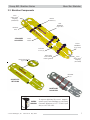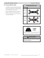
1
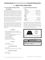
Users’ Manual
Scoop EXL
Stretcher Series
May 2006 GLO
Pub. No. 234-2125-05
Scoop EXL Stretcher Series
Disclaimer
This manual contains general instructions for the use, operation and
care of this product. The instructions are not all-inclusive. Safe and
proper use of this product is solely at the discretion of the user. Safety
information is included as a service to the user. All other safety
measures taken by the user should be within and under consideration
of applicable regulations. It is recommended that training on the proper
use of this product be provided before using this product in an actual
situation.
Retain this manual for future reference. Include it with the product in
the event of transfer to new users. Additional free copies are available
upon request from Customer Service.
Proprietary Notice
The information disclosed in this manual is the property of FernoWashington, Inc., Wilmington, Ohio, USA. Ferno-Washington, Inc.,
reserves all patent rights, proprietary design rights, manufacturing
rights, reproduction use rights, and sales use rights thereto, and to any
article disclosed therein except to the extent those rights are expressly
granted to others or where not applicable to vendor proprietary parts.
© Copyright Ferno-Washington, Inc. All rights reserved.
Ferno-Washington, Inc.
70 Weil Way
Wilmington, OH 45177-9371, U.S. A
Telephone (Toll Free) ......................... 1.877.733.0911
Telephone ........................................... 1.937.382.1451
Fax (Toll Free) .................................... 1.888.388.1349
Fax ..................................................... 1.937.382.6569
Internet ............................................... www.ferno.com
2
© Ferno-Washington, Inc. 234-2125-05 May 2006
Scoop EXL Stretcher Series
TABLE OF CONTENTS
Section
Page
Section
Page
1 - Safety Information ..................................................... 4
5 - Maintenance ........................................................ 14-16
1.1 Warning ................................................................ 4
5.1 Maintenance Schedule ....................................... 14
1.2 Important .............................................................. 4
5.2 Disinfecting the Stretcher .................................. 14
1.3 Bloodborne Disease Notice ................................. 4
5.3 Cleaning the Stretcher ........................................ 14
2 - Operator Skills and Training .................................... 5
5.4 Disinfecting and Cleaning the Restraints .......... 14
2.1 Skills .................................................................... 5
5.5 Inspecting the Stretcher ..................................... 15
2.2 Training ................................................................ 5
5.6 Lubricating the Stretcher ................................... 15
3 - About the Stretcher ................................................ 6, 7
5.7 Checking/Securing Pins in the Couplings ....... 15, 16
3.1 Scoop EXL Stretcher Series Description ............ 6
6 - Stretcher Setup ................................................... 17, 18
3.2 General Specifications ......................................... 6
6.1 Attaching Restraints to the Scoop EXL and Scoop
3.3 Stretcher Components .......................................... 7
EXL Mortuary Stretchers .................................. 17
4 - Using the Stretcher ............................................... 8-13
6.2 Attaching Restraints to the Scoop EXL Stretcher
4.1 Before Placing the Stretcher in Service ............... 8
with Pins ............................................................ 18
4.2 General Guidelines for Use ................................. 8
7 - Parts and Service ..................................................... 19
4.3 Folding/Unfolding the Stretcher .......................... 8
8 - Accessories and Related Products .......................... 20
4.4 Adjusting the Stretcher Length ............................ 9
9 - Limited Warranty .................................................... 21
4.5 Applying the Stretcher ....................................... 10
10 - Ferno Customer Relations .................................... 21
4.6 Applying the Stretcher in a “V” Configuration .. 11
Training Record ............................................................. 22
4.7 Lifting and Carrying the Stretcher ..................... 12
Maintenance Record ..................................................... 23
4.8 Using Additional Help ....................................... 13
Illustrations
Illustration
Page
Illustration
Page
Stretcher Components ....................................................... 7
Figure 10 - Lifting the Stretcher ...................................... 12
Figure 1 - Stretcher in Folded Position ............................. 8
Using Additional Help ..................................................... 13
Figure 2 - Foot Section Locking Positions ........................ 9
Maintenance Schedule ..................................................... 14
Figure 3 - Using the Lock-Pin Lever ................................ 9
Figure 11 - Pin in Coupling Half ..................................... 15
Figure 4 - End Coupling Joined ...................................... 10
Figure 12 - Attaching a Two-Piece Restraint .................. 17
Figure 5 - Pressing the Lock Levers and Separating
Figure 13 - Attaching a Speed Clip to a Pin .................... 18
the End Coupling ............................................. 10
Figure 6 - Applying the Stretcher Halves ........................ 10
Figure 7 - Fastening Restraints ........................................ 10
Figure 14 - Speed Clip Attached from Top of
Stretcher ........................................................ 18
Figure 15 - Speed Clip Attached from Underside of
Figure 8 - Applying Stretcher in a “V” Configuration ..... 11
Stretcher ........................................................ 18
Figure 9 - Preparing to Lift the Stretcher ........................ 12
Parts Diagram .................................................................. 19
Serial Number Location .................................................. 21
© Ferno-Washington, Inc. 234-2125-05 May 2006
3
Safety Information
Scoop EXL Stretcher Series
1 - SAFETY INFORMATION
1.1 Warning
1.2 Important
Warning notices indicate a potentially hazardous
situation which, if not avoided, could result in injury. .
Important notices emphasize important usage or
maintenance information.
! WARNING
Untrained operators can cause injury or be
injured. Permit only trained personnel to
operate the stretcher.
Improper use of the stretcher can cause
injury. Use the stretcher only for the purpose
described in this manual.
Improper operation can cause injury. Operate
the stretcher only as described in this
manual.
An unattended patient can be injured. Stay
with the patient at all times.
Important
Do not attach lifting devices (such as ropes or
bridles) to stretcher handholds or pins. Always
lift and carry the stretcher by hand, grasping
the handholds and main frame. In heavy rescue
situations, secure the stretcher in a transport
basket and attach lifting devices to the basket.
1.3 Bloodborne Disease Notice
To reduce the risk of exposure to bloodborne diseases
such as HIV-1 and hepatitis when using the Scoop EXL
Stretcher, follow the disinfecting and cleaning
instructions in this manual.
An unrestrained patient can fall off the
stretcher and be injured. Use restraints to
secure the patient on the stretcher.
Helpers can cause injury or be injured.
Operate and maintain control of the stretcher
and direct all helpers.
Improper maintenance can cause injury.
Maintain the stretcher only as described in
this manual.
Improper parts and service can cause injury.
Use only Ferno parts and Ferno-approved
service on the stretcher.
Modifying the stretcher can cause injury and
damage. Use the stretcher only as designed
by Ferno.
Attaching improper items to the stretcher can
cause injury. Use only Ferno-approved items
on the stretcher.
4
© Ferno-Washington, Inc. 234-2125-05 May 2006
Scoop EXL Stretcher Series
Operator Skills and Training
2 - OPERATOR SKILLS AND TRAINING
2.1 Skills
Operators using the stretcher need:
a working knowledge of emergency patienthandling procedures.
! WARNING
Untrained operators can cause injury or be
injured. Permit only trained personnel to
operate the stretcher.
the ability to assist the patient.
a complete understanding of the procedures
described in this manual.
2.2 Training
Trainees need to:
follow a training program designed by their
training officer.
read this manual. For additional free users’
manuals, contact your Ferno distributor or Ferno
Customer Relations (page 21).
© Ferno-Washington, Inc. 234-2125-05 May 2006
practice with the stretcher before using it in
regular service.
be tested on their understanding of the stretcher.
record their training information. A sample
training record sheet is provided on page 22.
5
About the Stretcher
Scoop EXL Stretcher Series
3 - ABOUT THE STRETCHER
3.1 Scoop EXL Stretcher Series
Description
The Scoop EXL Stretcher (called the “stretcher” in
this manual) is a patient-handling device designed to
“scoop” patients from the ground or floor in confined
spaces, or when the patient needs to be moved with
little change of body position. The stretcher is for
professional use by a minimum of two trained operators.
The stretcher series comprises three models: Scoop
EXL Stretcher; Scoop EXL Stretcher with Pins; and
Scoop EXL Mortuary Stretcher. Operation of all
stretcher models is identical. The type of patient
restraints selected or supplied varies.
All three models of the stretcher are constructed in two
halves that uncouple to slide under the patient or body,
then re-couple for lifting. The stretcher may also be
uncoupled at only the foot end and opened into a “V”
configuration to “scoop” the patient or body. Other
features are:
3.2 General Specifications
Length
Maximum ................................... 79 in (201 cm)
Intermediate 1 ............................. 74 in (189 cm)
Intermediate 2 ............................. 70 in (177 cm)
Minimum .................................... 65 in (165 cm)
Folded ......................................... 47 in (120 cm)
Width .............................................. 17 in (43 cm)
Depth
Open ................................................. 3 in (7 cm)
Folded ............................................... 3 in (8 cm)
Weight ................................................ 18 lb (8 kg)
Load Limit .................................. 350 lb (159 kg)
General specifications are rounded to the nearest whole
number. Metric conversions are calculated before
rounding the English measurements. For more
information, contact Ferno Customer Relations (page
21) or your Ferno distributor. Ferno reserves the right
to change specifications without notice.
ALL MODELS
• Polymer panel material is X-ray translucent,
impervious to fluids, and does not conduct heat or
cold to the patient.
• Telescoping foot section adjusts to four locking
positions for length adjustment
• Four corner handholds
• Eight side handholds
• Stretcher folds for storage
• Twin Safety Lock® couplings
SCOOP EXL
• Color: Yellow
• Set of 3 patient restraints
350 lb
159 kg
LOAD
LIMIT
Inspect the stretcher if the load limit has been
exceeded (see Inspecting the Stretcher, page 15).
! WARNING
Improper use of the stretcher can cause
injury. Use the stretcher only for the purpose
described in this manual.
SCOOP EXL WITH PINS
• Color: Yellow
• Eight pins for attaching restraints with speed clips
MORTUARY SCOOP EXL
• Color: Gray
• Set of 3 restraints
6
© Ferno-Washington, Inc. 234-2125-05 May 2006
Scoop EXL Stretcher Series
About the Stretcher
3.3 Stretcher Components
Twin
Safety-Lock®
Coupling
(Head End)
Patient
Restraint (3)
Side
Handhold
(4 per side)
Headrest
Area
STANDARD
SCOOP EXL
Torso
Panel
Corner
Handhold
(2 per end)
Lock Pin
Lever (2)
Telescoping
Foot Section
with Leg Panels
Pin for Speed Clip
(4 per side)
Twin
Safety-Lock®
Coupling
(Foot End)
Restraint
(3)
SCOOP EXL
WITH PINS
MORTUARY
SCOOP EXL
USERS’
MANUAL
© Ferno-Washington, Inc. 234-2125-05 May 2006
To request additional free users’ manuals,
contact your Ferno distributor or call Ferno
Customer Relations at 1.877.733.0911 (toll
free) or 1.937.382.1451.
7
Using the Stretcher
Scoop EXL Stretcher Series
4 - USING THE STRETCHER
4.1 Before Placing the Stretcher
in Service
1. Personnel who will use the stretcher need to read
this manual.
! WARNING
Improper operation can cause injury. Operate
the stretcher only as described in this
manual.
2. Set up the stretcher, following the instructions in
Stretcher Setup, pages 17 and 18.
3. Confirm that the stretcher operates properly. See
Inspecting the Stretcher, page 15.
4.2 General Guidelines for Use
! WARNING
An unattended patient can be injured. Stay
with the patient at all times.
A minimum of two trained operators is required.
Operators may need help when working with
heavy patients. For placement and direction of
helpers, see Using Additional Help, page 13.
Follow standard patient-handling procedures
when using the stretcher.
! WARNING
An unrestrained patient can fall off the
stretcher and be injured. Use restraints to
secure the patient on the stretcher.
Stay with the patient at all times.
Always use patient restraints.
4.3 Folding/Unfolding the Stretcher
To fold the stretcher:
1. Lay the stretcher flat on the floor or ground.
2. Move the lock-pin levers to the unlocked position
(the upper notch, as in Figure 3, page 9).
3. Fully extend the foot section by pulling it out until
the hinges are completely visible.
4. Lift the foot section and fold it over onto the torso
panel (Figure 1).
Figure 1 - Stretcher in Folded Position
The stretcher can be stored folded or in the shortest
unfolded position.
To unfold the stretcher: lay the stretcher flat on the
floor or ground. Lift the foot section off the torso panel
and unfold until it lies flat, then follow instructions in
Adjusting the Stretcher Length, page 9.
8
© Ferno-Washington, Inc. 234-2125-05 May 2006
Using the Stretcher
Scoop EXL Stretcher Series
Closed Position
4.4 Adjusting the Stretcher Length
The stretcher length can be adjusted to the patient’s
height by moving the telescoping foot section to one of
four locking positions (Figure 2).
To determine if length adjustment is needed, position
the stretcher beside the patient and align the headrest
area with the patient’s nose. Adjust the foot section to
extend a little beyond the bottom of the patient’s feet.
Extended Positions (3)
Adjust the length of the stretcher before uncoupling
the halves. This ensures equal adjustment to both
halves.
TO LENGTHEN OR SHORTEN THE STRETCHER
1. Move the lock-pin lever on each side of the frame
to the unlocked position (Figure 3).
Note: When the stretcher is lying face-up on a flat
surface, the locked position is “down” and the unlocked
position is “up” (Figure 3).
2. Pull the foot section outward to the desired length,
stopping near one of the locking positions located
at the holes along the foot-section frame.
3. Return both lock-pin levers to the locked position
(Figure 3).
Figure 2 - Foot Section Locking Positions
4. Push or pull the foot section a little until it locks
into place.
5. Make sure both sides are securely locked.
Locked
Unlocked
Figure 3 - Using the Lock-Pin Lever
© Ferno-Washington, Inc. 234-2125-05 May 2006
9
Using the Stretcher
4.5 Applying the Stretcher
Scoop EXL Stretcher Series
Twin Safety Lock® Levers
To apply the stretcher to a patient, separate the stretcher
halves and use local protocols when carefully moving
the stretcher under the patient as follows:
1. Unfold the stretcher (See Folding/Unfolding the
Stretcher, page 8).
2. Lay the stretcher next to the patient and adjust
the length to the patient’s height (see Adjusting
Stretcher Length, page 9).
Figure 4 - End Coupling Joined
3. Unfasten the restraints (if stored on stretcher).
4. To separate the stretcher halves, unlock the Twin
Safety Lock® coupling (Figure 4) at each end of
the stretcher. To unlock a coupling, press both
levers of the Twin Safety Lock® and pull the
coupling halves away from each other (Figure 5).
5. Position half of the stretcher on each side of the
patient, aligning the center of the headrest area
with the patient’s nose (Figure 6).
6. Use local protocols to carefully work the stretcher
halves under the patient until the end couplings
meet.
Note: Use care to avoid pinching or pulling the
patient’s skin, hair, or clothing while working the
stretcher halves into place.
Figure 5 - Pressing the Lock Levers and
Separating the End Coupling
Headrest Area Centered
with Patient’s Nose
7. To rejoin the stretcher halves, align the right and
left halves of the head and foot couplings and push
them together until the Twin Safety Locks®
engage.
8. Check that the Twin Safety Locks® at both ends
of the stretcher are fully engaged.
To test for proper lock engagement, pull the
coupling halves away from each other without
pressing on the lock levers. The couplings will
remain securely joined if the locks are fully
engaged.
Foot Panel
Adjusted to
Patient’s Height
Figure 6 - Applying the Stretcher Halves
9. Fasten and tighten all patient restraints (Figure 7).
Figure 7 - Fastening Restraints
10
© Ferno-Washington, Inc. 234-2125-05 May 2006
Scoop EXL Stretcher Series
4.6 Applying the Stretcher in a “V”
Configuration
1. Unfold the stretcher and adjust the length (see
Adjusting Stretcher Length, page 9).
Using the Stretcher
Head-End Closed
Foot-End Open
2. Unfasten the restraints (if stored on stretcher).
3. Open only the foot-end coupling. To open, press
the Twin Safety Lock® levers on the foot-end
coupling and pull the foot-end halves of the
stretcher apart to form an inverted “V.”
4. Position the stretcher with the patient’s head at
the coupled head-end of the stretcher (Figure 8).
5. Use local protocols to work the stretcher inward
and under the patient. Work from head to foot
until the coupling halves at the foot end meet.
Figure 8 - Applying Stretcher in “V”
Configuration
Note: Use care to avoid pinching or pulling the
patient’s skin, hair, or clothing while working the
stretcher halves into place beneath the patient.
6. Push the foot-end coupling halves together until
the Twin Safety Locks® meet and lock.
7. Check that the Twin Safety Locks® at both ends
of the stretcher are fully engaged.
To test for proper lock engagement, pull the
coupling halves away from each other without
pressing on the lock levers. The couplings will
remain securely joined if the locks are fully
engaged.
8. Fasten and tighten all patient restraints.
© Ferno-Washington, Inc. 234-2125-05 May 2006
11
Using the Stretcher
Scoop EXL Stretcher Series
4.7 Lifting and Carrying
the Stretcher
•
•
Always lift and carry the stretcher by hand. Do
not attach lifting devices such as ropes or bridles
to the stretcher handholds or pins.
For heavy rescue situations, secure the stretcher
in a transport basket and attach the lifting devices
to the basket.
Use a minimum of two operators to lift the
stretcher. Use two operators and two helpers to
maintain stability of the stretcher when carrying
an adult patient.
Figure 9 - Preparing to Lift the Stretcher
To carry the stretcher:
1. Operators stand at opposite ends of the stretcher.
Helpers position themselves as shown in Using
Additional Help, page 13.
2. Grasp the handholds with an underhand grip
(palms up), Figure 9.
3. Use proper lifting techniques to lift and carry the
stretcher and patient (Figure 10).
Note: Lift only the weight you can safely handle.
Use additional help as needed when lifting and
carrying the stretcher. See Using Additional Help,
page 13.
Figure 10 - Lifting the Stretcher
Important
Do not attach lifting devices (such as ropes or
bridles) to stretcher handholds or pins. Always
lift and carry the stretcher by hand, grasping
the handholds and main frame. In heavy rescue
situations, secure the stretcher in a transport
basket and attach lifting devices to the basket.
12
© Ferno-Washington, Inc. 234-2125-05 May 2006
Scoop EXL Stretcher Series
Using the Stretcher
4.8 Using Additional Help
•
At minimum, two trained operators are required
to operate the stretcher. They will need help when
carrying the stretcher with an adult patient and
when working with a heavy patient.
•
Operators should maintain control of the stretcher,
operate moving parts, and direct any helpers.
•
The chart at right shows the suggested placement
for operators and helpers.
Using Additional Help
Helpers
Lifting and Carrying
Two
Operators
+
Two
Helpers
Two
Operators
+
Four
Helpers
Key:
O = Operator
350 lb
159 kg
H = Helper
P = Patient
LOAD
LIMIT
Inspect the stretcher if the load limit has been
exceeded (see Inspecting the Stretcher, page 15).
! WARNING
Helpers can cause injury or be injured.
Operate and maintain control of the stretcher
and direct all helpers.
© Ferno-Washington, Inc. 234-2125-05 May 2006
13
Maintenance
Scoop EXL Stretcher Series
5 - MAINTENANCE
5.1 Maintenance Schedule
5.2 Disinfecting the Stretcher
The stretcher requires regular maintenance. Set up and
follow a maintenance schedule. A sample maintenance
record sheet is provided on page 23. The table below
represents minimum intervals for maintenance.
Disinfecting (this page)
Each Month
As Needed
Maintenance
(Minimum Intervals)
Each Use
When using maintenance products, follow the
manufacturers’ directions and read the manufacturers’
material safety data sheets.
•
1. Wipe all surfaces with disinfectant after each use.
Follow disinfectant manufacturer’s instructions.
2. Inspect the stretcher for obvious damage as you
disinfect it.
Important
Disinfectants and cleaners containing bleach,
phenolics, or iodines can damage the stretcher.
Disinfect and clean only with products that do
not contain these chemicals.
5.3 Cleaning the Stretcher
Cleaning (this page)
•
Inspecting (page 15)
•
Lubricating (page 15)
•
Clean the stretcher with warm, soapy water and a cloth
or soft brush, or wipe with a mild solvent.
•
The stretcher panels are composed of a polymer
material that does not require waxing.
Important
! WARNING
Improper maintenance can cause injury.
Maintain the stretcher only as described in
this manual.
Steam and water under high pressure penetrate
joints, flush away lubricant, and cause
corrosion. Do not use steam or a high-pressure
washer to clean the stretcher.
5.4 Disinfecting and Cleaning
the Restraints
Disinfecting and cleaning procedures vary according
to restraint model. For disinfecting and cleaning
instructions, refer to the restraint users’ manual
packaged with the restraints.
Important
Restraints may be damaged by improper
maintenance. Follow the disinfecting and
cleaning instructions in the restraint users’
manual packaged with the restraints.
14
© Ferno-Washington, Inc. 234-2125-05 May 2006
Maintenance
Scoop EXL Stretcher Series
5.5 Inspecting the Stretcher
5.6 Lubricating the Stretcher
Have your service’s equipment maintenance personnel
inspect the stretcher regularly. Follow the checklist
below and work the stretcher through all its functions
as described in this manual.
The stretcher’s head-end and foot-end couplings are
lubricated during assembly but may require additional
lubrication with use.
INSPECTION CHECKLIST
Are all components present?
Is the stretcher free of excessive wear?
Do all moving parts (couplings, levers, hinges,
and sliding frame) operate smoothly and
properly?
Are the coupling pins securely in place? (See
subsection 5.7, pages 15 and 16.)
Does the foot section lock properly into each
position?
Are all 8 speed-clip pins securely in place?
(For stretchers with pins.)
Do the head- and foot-end couplings require
lubrication?
Is restraint webbing in good condition with
no cuts or frayed edges?
Are restraint buckles free of visible damage
and do they operate properly?
Do speed clips on restraints function properly?
If inspection indicates damage or excessive wear, take
the stretcher out of service until repairs are made (see
Parts and Service, page 19).
If inspection indicates damage or excessive wear to
restraint(s), take restraint(s) out of service and destroy
to prevent accidental use. For replacement restraints,
contact your Ferno distributor or Ferno Customer
Relations (page 21).
Choose one of the following lubrication methods. Apply
lubricant(s) to the points indicated below:
METHOD A
(WHITE LITHIUM GREASE)
1. Apply a small amount of white lithium grease to
the sliding surfaces of the end couplings.
2. Wipe off excess lubricant.
METHOD B
(DRY-COATING TEFLON™ LUBRICANT)
1. Spray a very small amount of general purpose,
dry coating Teflon™ lubricant onto the sliding
surfaces of the end couplings. Follow the lubricant
manufacturer’s instructions.
2. Wipe off excess lubricant.
5.7 Checking and Securing Pins in
the Couplings
Follow the instructions below to check that the pins in
the Twin Safety Lock® couplings are securely in place.
If a pin has loosened, follow the instructions on page
16 to tighten it. If a pin is missing, remove the stretcher
from service until the pin has been replaced (see Parts
and Service, page 19).
CHECKING THE PINS
There are four threaded pins in the couplings: one pin
in each half of each coupling (Figure 11). Loctite® 270
threadlocker is applied to the pins during assembly of
Pin
Keep maintenance records.
Figure 11 - Pin in Coupling Half
© Ferno-Washington, Inc. 234-2125-05 May 2006
15
Maintenance
Scoop EXL Stretcher Series
the stretcher. If a pin becomes loose, it can be tightened
by applying additional threadlocker as directed below
in Reinstalling a Pin.
To check for loose pins:
1. Use pliers that are maximum 1/2 inch (12mm)
thick.
2. Wrap tape around the pliers jaws to prevent
damaging the pins.
3. Attempt to unthread the first pin. If the pin holds
and you cannot unthread it without extra effort, it
is secure and no repair is needed on that pin.
If you are able to unthread the pin, follow
instructions in Reinstalling a Pin, below.
4. Check the remaining three pins and reinstall any
that are not securely in place.
REINSTALLING A PIN
1. Finish unthreading the loose pin and remove it
from the Twin Safety Lock®.
2. Remove any particles of used threadlocker from
the screw thread and the lock body.
3. Dry the cleaned surfaces of the pin and lock body.
4. Apply Loctite® 270 to the dry screw thread until
the thread is fully covered with the threadlocker.
5. Insert the pin into the lock body and thread the
pin in using the pliers.
6. Remove all excess threadlocker material.
7. Allow the threadlocker to cure for several hours
before returning the stretcher to service.
16
© Ferno-Washington, Inc. 234-2125-05 May 2006
Scoop EXL Stretcher Series
Stretcher Setup
6 - STRETCHER SETUP
6.1 Attaching Restraints to the
Scoop EXL and Scoop EXL
Mortuary Stretchers
The Scoop EXL Stretcher and the Scoop EXL Mortuary
Stretcher include a set of three patient restraints. The
restraints may be constructed in one or two pieces.
Follow the setup instructions that apply to the restraints
shipped with your stretcher.
Important
Restraints fitted with plastic buckles (Model
430-P and 430-PA) are secondary restraints.
Do not use them on ambulance cots or other
equipment requiring primary restraints. Use
only as described in the restraint users’ manual.
TWO-PIECE RESTRAINTS
To attach a two-piece restraint:
1. Unbuckle the restraint, separating it into two
pieces.
2. Pass the looped end of one restraint piece upward
through a handhold opening on the stretcher frame
(Figure 12).
3. Hold the loop open and thread the buckle of the
restraint through the loop (Figure 12).
4. Pull the buckle and webbing through the loop until
the loop is snug against the stretcher frame.
Buckle
ONE-PIECE RESTRAINTS
To attach a one-piece restraint:
1. Place the patient on the stretcher using local
protocols and following the instructions in this
manual.
2. One operator lifts one end of the stretcher while
the other operator places the one-piece restraint
under the stretcher.
Loop
Handhold
Opening
3. Feed the restraint up through the handholds and
fasten it around the patient.
4. Repeat Steps 2-3 to attach additional restraints.
5. Confirm that all restraints are securely fastened.
Figure 12 - Attaching a Two-Piece Restraint
5. Repeat Steps 2-4 to attach the other half of the
restraint to opposite handhold.
6. Repeat Steps 1-5 to attach additional restraints.
7. Confirm that all restraints are securely fastened.
© Ferno-Washington, Inc. 234-2125-05 May 2006
17
Stretcher Setup
Scoop EXL Stretcher Series
6.2 Attaching Restraints to the
Scoop EXL Stretcher with Pins
The Scoop EXL Stretcher with Pins requires restraints
fitted with speed clips. Ferno recommends using fiveor seven-foot, two-piece restraints.
Pin
Important
Restraints fitted with plastic buckles (Model
773-P) are secondary restraints. Do not use
them on ambulance cots or other equipment
requiring primary restraints. Use only as
described in the restraint users’ manual.
Spring Latch
Figure 13 - Attaching a Speed Clip to a Pin
To attach a speed clip to the pin:
1. Unbuckle the restraint, separating it into two
pieces.
2. Press the spring latch of the speed clip against a
speed clip pin (Figure 13) until the clip snaps into
place around the pin (Figure 14).
3. Confirm that the speed clip is securely fastened
to the pin.
4. Repeat Steps 2 and 3 to fasten the other half of
the restraint to the matching pin on the opposite
side of the stretcher.
5. Attach remaining restraints following Steps 1-4.
Figure 14 - Speed Clip Attached
from Top of Stretcher
(viewed from
top of stretcher)
Note: Speed clips are usually attached from the top of
the stretcher as in Figure 14, but this may be difficult
in some situations. If the patient is large or lying in an
unusual position, it may be easier to attach speed clips
from the underside of the stretcher as in Figure 15.
Important
Do not attach lifting devices (such as ropes or
bridles) to stretcher handholds or pins. Always
lift and carry the stretcher by hand, grasping
the handholds and main frame. In heavy rescue
situations, secure the stretcher in a transport
basket and attach lifting devices to the basket.
18
Figure 15 - Speed Clip Attached
from Underside of Stretcher
(viewed from
top of stretcher)
© Ferno-Washington, Inc. 234-2125-05 May 2006
Scoop EXL Stretcher Series
Parts and Service
7 - PARTS AND SERVICE
7.1 Parts and Service U.S.A. and Canada
To order stretcher parts or for professional stretcher
repair, contact EMSAR® - the only agent authorized by
Ferno to manage, service, and repair Ferno products.
EMSAR factory-trained technicians use Fernoapproved parts and repair procedures. EMSAR has a
franchise location serving you. For details, phone, fax,
or visit EMSAR’s web site.
! WARNING
Improper parts and service can cause injury.
Use only Ferno parts and Ferno-approved
service on the stretcher.
1.800.73.EMSAR (Phone)
1.937.383.1051 (Fax)
www.EMSAR.com (Internet)
7.2 Parts and Service Worldwide
! WARNING
Modifying the stretcher can cause injury and
damage. Use the stretcher only as designed
by Ferno.
To order Ferno parts and for professional stretcher
repair, contact your Ferno distributor. Your distributor
is the only agent authorized by Ferno to manage,
service, and repair Ferno products.
7.3 Parts List
Ref.#
Yellow
Part #
Description
Gray
Part #
1 ......... Two folding hinges (right/left) with lock pin levers ................................ 190-1041 ...................... 190-1041
2 ......... Two folding hinges (right/left) w/torso panels (right/left) ...................... 190-1042 ...................... 190-1345
3 ......... Two folding hinges (right/left) w/foot panels (right/left) ........................ 190-1043 ...................... 190-1346
4 ......... Folding hinge, lock pin lever w/torso panel (patient’s left) ..................... 190-1044 ...................... 190-1347
5 ......... Folding hinge, lock pin lever w/torso panel (patient’s right) .................. 190-1045 ...................... 190-1348
6 ......... Folding hinge, lock pin lever w/foot panel (patient’s left) ...................... 190-1046 ...................... 190-1349
7 ......... Folding hinge, lock pin lever w/foot panel (patient’s right) .................... 190-1047 ...................... 190-1350
8 ......... Pins for Twin Safety Lock coupling, M8X.75 (pair) ............................... 190-1584 ...................... 190-1584
9 ......... Restraints (see Accessories, page 20)
4
2
8
6
1
5
9
© Ferno-Washington, Inc. 234-2125-05 May 2006
3
8
7
19
Accessories and Related Products
Scoop EXL Stretcher Series
8 - ACCESSORIES AND RELATED PRODUCTS
The Ferno accessories listed here are approved for use
with the stretcher. Ferno also has a full line of
emergency products for the EMS professional.
Always follow the instructions packed with accessories.
Keep the instructions with this manual. Contact Ferno
Customer Relations (page 21) or your Ferno distributor
for product information.
Part
Description
430 Restraint (nylon webbing, metal buckle)
1-pc., 7-ft. maroon .................................031-2600
2-pc., 5-ft. maroon .................................031-3752
430-PA Restraint for EXL (polyester webbing, plastic
buckle)
2-pc., 5-ft. maroon .................................031-4018
773-P Restraint w/ Swivel Speed Clips (plastic buckle)
2-pc., 5-ft burgundy ...............................031-3992
770 Fastrap™ Restraint System ....................031-3265
449 WizLoc® Cervical Collar (3-pack) ........081-9750
455 HeadHugger™ Disposable Head Immobilizer
(10 pack) ................................................083-1919
Universal Scoop Storage Brackets ...............081-9876
71 Basket Stretcher .......................................010-7100
71-S (Split) Basket Stretcher ........................010-7130
! WARNING
Attaching improper items to the stretcher can
cause injury. Use only Ferno-approved items
on the stretcher.
20
© Ferno-Washington, Inc. 234-2125-05 May 2006
Scoop EXL Stretcher Series
Warranty, Ferno Customer Relations
9 -WARRANTY
Limited Warranty Summary
Ferno products are warranted to be free from defects in material and workmanship for a period of one year, except:
• External finishes (gelcoat, paint, powdercoat, decals, etc.) are warranted for 90 days.
• Soft goods (webbing, vinyl, fabric, foam, etc.) are warranted for 90 days.
• Fiberglass AquaCiser tanks are warranted against leakage for 5 years.
• Stainless hydrotherapy tanks are warranted against tank shell leakage and corrosion for 5 years.
• Mortuary products (except hydraulic parts and soft goods) are warranted for 2 years.
• Ambulance cots and ambulance transporters (except external finish and soft goods) are warranted for 2 years.
• EZ Glide™ Chairs are warranted for 2 years.
• EMS bags (replaceable bottom excluded) and backboards are warranted for lifetime replacement. (Damage caused by
accident, abuse, misuse or improper care will be repaired at a reasonable charge for which you will be informed prior to
the repair work being done.)
• Integrated Charging System (ICS) is warranted for 2 years
Ferno repairs are warranted for 90 days from the date of repair.
This limited warranty applies only when the product is used as described in the instructions provided. The warranty period
begins when the product is shipped from Ferno or when you receive it if you have proof of delivery. Shipping charges are not
covered by this limited warranty. Ferno is not liable for shipping damages or damages sustained through using the product.
Non-Ferno products sold by Ferno retain the product manufacturer’s original warranties. Ferno offers no warranties of any
kind additional to those of the product manufacturer, nor does Ferno assume any liability for products manufactured by others.
Limited Warranty Obligation
If a product is proven defective, Ferno will repair or replace it, or, at our option, refund the item’s purchase price. In no event
is Ferno liable for more than the selling price of the product. The purchaser accepts these terms in lieu of all damages.
This is a summary of the limited warranty. The actual terms and conditions of the limited warranty, and the limitations
of liability and disclaimers, are available upon request by calling 800-733-3766 or 937-382-1451.
10 - FERNO CUSTOMER RELATIONS
Customer service and product support are important
aspects of each Ferno product. For assistance, please
contact Ferno Customer Relations:
Serial Number
Please have the serial number of your Scoop EXL
Stretcher available when calling Ferno Customer
Relations, and include it in all written communications.
Telephone (Toll-free).......................... 1.877.733.0911
Telephone ........................................... 1.937.382.1451
Fax (Toll-free) .................................... 1.888.388.1349
Fax ...................................................... 1.937.382.6569
Internet ............................................... www.ferno.com
© Ferno-Washington, Inc. 234-2125-05 May 2006
(Serial Number located on
underside of stretcher)
21
Scoop EXL Stretcher Series
TRAINING RECORD
Date
22
Name
Training Method
© Ferno-Washington, Inc. 234-2125-05 May 2006
Scoop EXL Stretcher Series
MAINTENANCE RECORD
Date
Maintenance Performed
© Ferno-Washington, Inc. 234-2125-05 May 2006
By
23