1
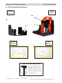
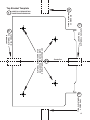
Installation and Users’ Manual
Accessory Kit 082-2072
Secure Lock Storage Brackets
For Model 59 Series
EZ Glide Evacuation Chairs
November 2005 GLO
Pub. No. 234-3340-00
Secure Lock Storage Brackets
Disclaimer
This manual contains general instructions for the use, operation and
care of this product. The instructions are not all-inclusive. Safe and
proper use of this product is solely at the discretion of the user. Safety
information is included as a service to the user. All other safety
measures taken by the user should be within and under consideration
of applicable regulations. It is recommended that training on the proper
use of this product be provided before using this product in an actual
situation.
Retain this manual for future reference. Include it with the product in
the event of transfer to new users. Additional free copies are available
upon request from Customer Relations.
Proprietary Notice
The information disclosed in this manual is the property of FernoWashington, Inc., Wilmington, Ohio, USA. Ferno-Washington, Inc.
reserves all patent rights, proprietary design rights, manufacturing
rights, reproduction use rights, and sales use rights thereto, and to any
article disclosed therein except to the extent those rights are expressly
granted to others or where not applicable to vendor proprietary parts.
© Copyright Ferno-Washington, Inc. All Rights Reserved.
Ferno-Washington, Inc.
70 Weil Way
Wilmington, OH 45177-9371 U.S.A.
Telephone (Toll Free) ......................... 1.877.733.0911
Telephone ........................................ +1.937.382.1451
Fax (Toll Free) ................................... 1.888.388.1349
Fax .................................................. +1.937.382.6569
Internet ............................................... www.ferno.com
2
© Ferno-Washington, Inc. 234-3340-00 November 2005
Secure Lock Storage Brackets
TABLE OF CONTENTS
Section
Page
Section
Page
1 - Safety Information ..................................................... 4
4 - Using the Brackets ................................................... 10
1.1 Warning ................................................................ 4
4.1 Securing the Chair In the Brackets .................... 10
1.2 Important.............................................................. 4
4.2 Removing the Chair From the Brackets ............ 10
1.3 Bloodborne Disease Notice ................................. 4
5 - Maintenance ............................................................. 11
5.1 Maintenance Schedule ........................................ 11
2 - About the Brackets ................................................. 4, 5
5.2 Disinfecting and Cleaning .................................. 11
2.1 Product Description ............................................. 4
5.3 Inspecting the Brackets ....................................... 11
2.2 General Specifications ......................................... 4
5.4 Lubrication ......................................................... 11
2.3 Kit Components ............................................... 4, 5
6 - Replacement Parts ................................................... 12
3 - Installation ............................................................... 6-9
6.1 Parts and Service - U.S.A. and Canada ............. 12
3.1 Selecting the Mounting Surface and Fasteners ... 6
6.2 Parts and Service - Worldwide .......................... 12
3.2 Selecting a Mounting Location ........................... 6
6.3 Parts List ............................................................ 12
3.3 Tools Required..................................................... 6
7 - Limited Warranty Statement .................................. 12
3.4 Additional Parts Needed ...................................... 6
8 - Ferno Customer Relations ...................................... 12
3.5 Mounting the Bottom Bracket ............................. 7
Bottom Bracket Template ............................................. 13
3.6 Mounting the Top Bracket ................................ 8,9
Top Bracket Template ................................................... 15
Illustrations
Kit Components ................................................................. 5
Figure 10 - Removing Bracket and Chair
Figure 1 - Minimum Mounting Space Required ............... 6
from Template ................................................. 9
Figure 2 - Bottom Template Taped to Bracket .................. 7
Figure 11 - Drilling the Mounting Holes .......................... 9
Figure 3 - Re-marking Holes on Template ........................ 7
Figure 12 - Mounting Top Bracket .................................... 9
Figure 4 - Drilling the Mounting Holes ............................ 7
Figure 13 - Chair Crosstube in Bracket .......................... 10
Figure 5 - Mounting Bottom Bracket ................................ 7
Figure 14 - Capturing Lift Bar in Bracket ....................... 10
Figure 6 - Re-mark Holes on Top Template ...................... 8
Figure 15 - Lift Bar Captured in Bracket Latch .............. 10
Figure 7 - Chair Resting in Bracket Cradle ....................... 8
Figure 16 - EZ Glide Chair Stored
Figure 8 - Bracket/Template Centered and Latched on Lift
in Secure Lock Mount ................................. 10
Bar (Above: front. Below: side) ........................ 8
Figure 17 - Releasing Chair from Bracket ...................... 10
Figure 9 - Sides of Template Taped to Wall ...................... 9
Serial Number Location .................................................. 12
© Ferno-Washington, Inc. 234-3340-00 November 2005
3
Safety Information, About the Brackets
Secure Lock Storage Brackets
1 - SAFETY INFORMATION
1.1 Warning
1.2 Important
Warning notices indicate a potentially hazardous
situation which, if not avoided, could result in injury
or death.
Important notices emphasize important usage or
maintenance information.
! WARNING
Improper use of the brackets can cause
injury. Use the brackets only for the purpose
described in this manual.
Improper maintenance can cause injury.
Maintain the brackets only as described in
this manual.
Improper parts can cause injury. Use only
Ferno parts on the brackets.
Important
It is the responsibility of the installer to select
mounting points and mounting fasteners that
will support the chair and brackets under all
conditions of use.
1.3 Bloodborne Disease Notice
To reduce the risk of exposure to bloodborne diseases
such as HIV-1 and hepatitis when using the brackets,
follow the disinfecting and cleaning instructions in this
manual.
Modifying the brackets can cause injury and
damage. Use the brackets only as designed
by Ferno.
2 - ABOUT THE BRACKETS
2.1 Product Description
2.2 General Specifications
Accessory Kit 082-2072 contains the Secure Lock
Storage Brackets (referred to as the bracket(s) in this
manual), a two-bracket storage system for use with a
Model 59, Model 59-T, or Model 59-E EZ Glide
Evacuation Chair.
Weight
Brackets Only ................................ 7.7 lb (3.5 kg)
Brackets + Chair
Maximum Weight* ............... 47.7 lb (21.6 kg)
* Maximum combined weight includes chair, brackets,
patient restraints, IV Bag Holder, Locking Auxiliary
Handles, and Headrest Assembly. Ferno reserves the
right to change specifications without notice.
The brackets may be mounted on the wall of an
ambulance or building. The bottom bracket supports the
rear-wheel crosstube of the folded chair. The top bracket
grasps the chair’s lift bar.
! WARNING
Improper use of the brackets can cause
injury. Use the brackets only for the purpose
described in this manual.
4
2.3 Kit Components
1 ea .................................................... Top Bracket
1 ea ............................................. Bottom Bracket
1 ea ...................... Installation and Users’ Manual
1 ea ........ Template for Bottom Bracket (Page 13)
1 ea .............. Template for Top Bracket (Page 15)
© Ferno-Washington, Inc. 234-3340-00 November 2005
Secure Lock Storage Brackets
About the Brackets
2.3 Kit Components (continued)
TOP
BRACKET
BOTTOM
BRACKET
Release
Handle
Cradle
Spring
BOTTOM
TEMPLATE
TOP
TEMPLATE
INSTALLATION AND USERS’ MANUAL
To request additional free
Installation and Users’
Manuals, contact Ferno
Customer Relations (Page
12) or visit us at
www.ferno.com
© Ferno-Washington, Inc. 234-3340-00 November 2005
5
Installation
Secure Lock Storage Brackets
3 - INSTALLATION
3.1 Selecting the Mounting Surface
and Fasteners
Because of the varying conditions of use and the variety
of surfaces that might be selected for mounting the
brackets, Ferno cannot recommend specific mounting
fasteners.
Important
It is the responsibility of the installer to select
mounting points and mounting fasteners that
will support the chair and brackets under all
conditions of use.
It is the responsibility of the installer to select mounting
points and mounting fasteners that are strong enough
to support the brackets and chair under all conditions
of use.
If the brackets are to be mounted in an ambulance,
backing plates or other support (not supplied) may be
needed, and the fasteners used should be SAE Grade
5, UNC 2.
MINIMUM MOUNTING SPACE REQUIRED
21 in. (53.3 cm)
Minimum Horizontal
Space Required
3.2 Selecting a Mounting Location
Select a mounting surface strong enough to support the
weight of the brackets and chair under all conditions
of use.
TOP BRACKET
Latch Handle
The available mounting space must be at least 21 in.
wide by 42 in. high (53.3 cm wide by 106.6 cm high ).
See Figure 1.
The height allows clearance for raising the latch handle
and the width accommodates the overall width of the
chair.
Do not use these figures to calculate placement of
fasteners. Follow the mounting instructions and use
the templates provided on Pages 13 and 15.
Template
42 in. (106.6 cm)
Minimum
Vertical Space
Required
BOTTOM BRACKET
3.3 Tools Required
• Level
• Masking tape
• Pencil
• Measuring tape
• Screwdriver
or wrench
• Drill
• Drill bit
3.4 Additional Parts Needed
8 ea ................... Appropriate Mounting Fasteners
(see Section 3.1 above)
6
Mount
Template
Figure 1
© Ferno-Washington, Inc. 234-3340-00 November 2005
Secure Lock Storage Brackets
Installation
3.5 Mounting the Bottom Bracket
Important
To ensure proper fit of the chair in the brackets,
the bottom bracket must be mounted before
the top bracket. Follow installation instructions
in this section (3.5) , then in Section 3.6.
Important
Figure 2 - Bottom Template Taped to Bracket
An improper installation surface, fastener, or
location can result in an unsatisfactory or
unsafe installation. Read and follow instructions
in Sections 3.1 and 3.2 on Page 6 before
beginning your installation.
1. The template for mounting the bottom bracket is
on Page 13. Remove and use the entire page.
2. Set the bottom bracket on the template, aligning
the bottom holes in the bracket with the bottom
hole markings on the template.
Figure 3 - Re-marking Holes on Template
Note: Because of tolerance variation during
manufacture, the bracket holes may not align perfectly
with the hole markings on the template. Align them as
evenly as possible.
3. Tape the template to the bracket flanges as
indicated on the template (Figure 2).
4. To ensure accuracy, re-mark the four mounting
points onto the template through the bracket holes
(Figure 3).
5. Hold the bracket/template unit against the
installation location on the wall and use a level
to make sure the bracket is straight.
Figure 4 - Drilling the Mounting Holes
6. Tape the sides of the template to the wall as
indicated on the template.
7. Peel the tape back from the flanges of the bracket
and lift the bracket off the template. Leave the
template taped on the wall.
8. Drill the holes for the fasteners (Figure 4) and
mount the bracket (Figure 5).
9. Verify the bracket is securely fastened to the wall.
© Ferno-Washington, Inc. 234-3340-00 November 2005
Figure 5 - Mounting Bottom Bracket
7
Installation
Secure Lock Storage Brackets
3.6 Mounting the Top Bracket
1. The template for mounting the top bracket is on
Page 15. Remove and use the entire page.
2. Set the top bracket on the template, aligning the
holes in the bracket as evenly as possible with
the hole markings on the template.
Re-Mark
Holes on
Template
3. Tape the template to the bottom edge and top
flange of the bracket.
4. To ensure accuracy, re-mark the four mounting
points onto the template through the bracket holes
(Figure 6).
Figure 6 - Re-mark Holes on Top Template
5. Place the lift bar of the EZ Glide Chair in the
lowest position, then fold the chair and check to
make sure it is locked.
6 . With the chair seat facing you, stand the rearwheels crosstube of the folded chair in the cradle
of the bottom bracket (Figure 7).
Rear-Wheels
Crosstube
7. Attach the top bracket (with template) to the lift
bar of the chair (see Step 3, Using the Brackets,
Page 10 for instructions.) Make sure the bracket
is centered on the lift bar (Figure 8, two views).
Cradle
Figure 7 - Chair Resting in Bracket Cradle
Lift
Bar
Figure 8 - Bracket/Template Centered and
Latched on Lift Bar
(Above: front view. Below: side view)
Release
Handle
Lift
Bar
8
© Ferno-Washington, Inc. 234-3340-00 November 2005
Secure Lock Storage Brackets
Installation
8. Hold the template and back of the bracket
flush against the wall and tape the sides of the
template to the wall as indicated on the template
(Figure 9).
9. Peel the tape back from the top and bottom of the
bracket and lift the bracket and chair off the
bottom bracket, leaving the template taped to
the wall (Figure 10).
10. Drill the four holes for the fasteners (Figure 11).
Figure 9 - Sides of Template Taped to Wall
11. Mount the bracket (Figure 12).
12. Verify that the bracket is securely fastened to the
wall.
Figure 10 - Removing Bracket from Template
(and Chair from Lower Bracket)
Figure 11 - Drilling the Mounting Holes
Figure 12 - Mounting Top Bracket
© Ferno-Washington, Inc. 234-3340-00 November 2005
9
Using the Brackets
Secure Lock Storage Brackets
4 - USING THE BRACKETS
4.1 Securing the Chair
in the Brackets
1. Place the lift bar in its lowest position, then fold
and lock the chair.
2. Hold the chair with the folded seat facing you
and rest the rear-wheels crosstube in the cradle
of the bottom bracket (Figure 13).
3. Firmly push the lift bar against the lower edge of
the bracket release handle (Figure 14) until the
handle latch captures the lift bar (Figure 15). Press
down on the release handle to make sure the
capture is complete.
Figure 15 - Lift Bar Captured in
Bracket Latch
Lift Bar
in Latch
When secured in both brackets, the chair will look
like the one in Figure 16.
4. Verify that the chair is secure in both brackets.
4.2 Removing the Chair
From the Brackets
Raise the red release handle (Figure 17), tilt the chair
forward, and lift it out of the bottom-bracket cradle.
Rear-Wheels
Crosstube
Rear-Wheels
Crosstube in
Cradle
Figure 16 - EZ Glide Chair in
Storage Brackets
Figure 13 - Chair Crosstube in Bracket
Figure 14 -Capturing Lift Bar in Bracket
10
Figure 17 - Releasing Chair from Bracket
© Ferno-Washington, Inc. 234-3340-00 November 2005
Secure Lock Storage Brackets
Maintenance
5 - MAINTENANCE
Improper maintenance can cause injury.
Maintain the brackets only as described in
this manual.
Minimum Intervals
for Maintenance
Each Month
When using maintenance products, follow the
manufacturers’ directions and read the manufacturers’
material safety data sheets. You can purchase a
recommended disinfectant from your Ferno distributor
or Ferno Customer Relations (Page 12).
! WARNING
As Needed
The brackets require regular maintenance. Set up and
follow a maintenance schedule. The table at the right
represents minimum intervals for maintenance.
Each Use
5.1 Maintenance Schedule
5.2 Disinfecting and Cleaning
Disinfect, clean, and inspect the mount at regular
intervals.
To disinfect the brackets: Remove the chair from the
brackets and wipe or spray all bracket surfaces with
disinfectant. Follow disinfectant manufacturer’s
instructions.
Ferno recommends inspecting all parts of the brackets
as you disinfect them.
To clean the brackets: Use a nonabrasive applicator
to clean the brackets with a solution of warm water
and a mild detergent. Rinse with a clean cloth dampened
with clean water. Dry with a towel.
5.3 Inspecting the Brackets
Have your equipment maintenance personnel inspect
the brackets regularly, following the list at the right. If
the inspection shows damage or excessive wear, replace
the bracket(s) or remove them from service until repair
is made.
5.4 Lubrication
The brackets do not require lubrication.
© Ferno-Washington, Inc. 234-3340-00 November 2005
Disinfecting (this page)
•
Cleaning (this page)
•
Inspecting (this page)
•
•
Important
Disinfectants and cleaners containing bleach,
phenolics, or iodines can damage the brackets.
Use caution when disinfecting and cleaning
with products containing these chemicals.
INSPECTION CHECKLIST
Are all components present?
Are all nuts and bolts securely in place?
Does the release handle function
properly?
Does the release-handle spring function
properly?
Are top and bottom brackets securely
fastened to the wall?
11
Parts, Warranty, Customer Relations
Secure Lock Storage Brackets
6 - REPLACEMENT PARTS
6.1 Parts and Service U.S.A. and Canada
To order parts in the U.S.A. and Canada, contact
EMSAR® - the only agent authorized by Ferno to
manage, service, and repair Ferno products. EMSAR
factory-trained technicians use Ferno-approved parts
and repair procedures. EMSAR has a franchise serving
you. For details, phone, fax, or visit EMSAR’s web site.
1.800.73.EMSAR (Phone)
1.937.383.1051 (Fax)
www.EMSAR.com (Internet)
! WARNING
Improper parts and service can cause injury.
Use only Ferno parts on the brackets.
! WARNING
Modifying the brackets can cause injury and
damage. Use the brackets only as designed
by Ferno.
6.2 Parts and Service Worldwide
6.3 Parts List
To order Ferno parts, contact your Ferno distributor.
Your distributor is the only agent authorized by Ferno
to manage, service, and repair Ferno products.
Spring ...........................................................190-1554
Top Bracket ..................................................090-5852
Bottom Bracket .............................................090-5853
Description
Part #
7 - LIMITED WARRANTY STATEMENT
The products sold by Ferno are covered by a limited warranty. The actual terms and conditions of the limited
warranty, and the limitations of liability and disclaimers, are available upon request by calling 1.800.733.3766 or
1.937.382.1451.
8 - FERNO CUSTOMER RELATIONS
Customer service and product support are important
aspects of each Ferno product. Please have the serial
number of your brackets available when calling Ferno
Customer Relations, and include it in all written
communications.
For assistance, please contact Ferno Customer
Relations:
Telephone (Toll-free).......................... 1.877.733.0911
Telephone ........................................... 1.937.382.1451
Fax (Toll-free) .................................... 1.888.388.1349
Fax ...................................................... 1.937.382.1191
Internet ............................................... www.ferno.com
12
Serial Number ________________________
© Ferno-Washington, Inc. 234-3340-00 November 2005
TEMPLATE TO WALL
3
2
TAPE BRACKET
TO TEMPLATE
HOLE MARKINGS ON TEMPLATE
SET BRACKET ON TEMPLATE AND
ALIGN HOLES IN BRACKET WITH
Centerline
LEVEL BRACKET
THEN TAPE SIDE OF
CAREFULLY REMOVE THIS PAGE
FROM THE MANUAL
1
4
Bottom Bracket Template
5
TAPE SIDE OF
TEMPLATE TO WALL
13
THIS PAGE LEFT BLANK INTENTIONALLY
14
3
TAPE SIDE OF
TEMPLATE TO WALL
CAREFULLY REMOVE THIS
PAGE FROM THE MANUAL
1
5
Top Bracket Template
TO BRACKET
TAPE BOTTOM
OF TEMPLATE
TO BRACKET
TAPE TOP OF TEMPLATE
4
HOLE MARKINGS ON TEMPLATE
SET BRACKET ON TEMPLATE AND
ALIGN HOLES IN BRACKET WITH
2
Centerline
6
TAPE SIDE OF
TEMPLATE TO WALL
15