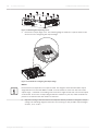
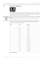
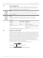
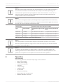
1
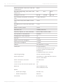
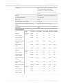
PROMATRIX 8000 POWER AMPLIFIER
en | User manual
PROMATRIX 8000 POWER AMPLIFIER
Table of contents | en
3
Table of contents
1
Safety information
4
2
Brief description
6
3
System overview
6
4
Scope of delivery and warranty
6
5
Installation
7
5.1
Front
7
5.2
Back
10
5.3
Installation
12
5.4
Cooling
12
6
Connections
13
6.1
Audio inputs
13
6.2
Power outputs on the output stage
15
6.3
CONTROL PORT
18
6.4
REMOTE CAN BUS
20
6.5
Supply voltage
22
6.6
End of line (EOL)
23
7
Configuration
25
7.1
Configuration of the output voltage
25
7.2
Setting the CAN address
28
7.3
Configuring the CAN baud rate
29
7.4
Pilot tone generator
30
7.5
Impedance measurement
30
8
Operation
31
9
Trouble shooting
33
10
Maintenance
33
11
Technical data
33
11.1
DPA 8150
33
11.2
DPA 8225
37
11.3
DPA 8412
40
11.4
Block diagram
42
11.5
Dimensions
43
User manual
19-Aug-13 | 03 | F01U217494
4
en | Safety information
1
PROMATRIX 8000 POWER AMPLIFIER
Safety information
Danger!
The lightning symbol inside a triangle notifies the user of high-voltage, uninsulated lines and
contacts inside the devices that could result in fatal electrocution if touched.
Warning!
!
An exclamation mark inside a triangle refers the user to important operating and service
instructions in the documentation for the equipment.
1.
Read these safety notes.
2.
Keep these safety notes in a safe place.
3.
Heed all warnings.
4.
Observe all instructions.
5.
Do not operate the device in close proximity to water.
6.
Use only a dry cloth to clean the unit.
7.
Do not cover any ventilation slots. Always refer to the manufacturer's instructions when
installing the device.
8.
Do not install the device close to heaters, ovens, or other heat sources.
9.
Note: The device must only be operated via the mains power supply with a safety ground
connector. Do not disable the safety ground connection function of the supplied power
cable. If the plug of the supplied cable does not fit your mains socket, please contact
your electrician.
10. Ensure that it is not possible to stand on the mains cable. Take precautions to ensure the
mains cable cannot become crushed, particularly near the device connector and mains
plug.
11. Only use accessories/extensions for the device that have been approved by the
manufacturer.
12. Unplug the device if there is risk of lightning strike or in the event of long periods of
inactivity. However, this does not apply if the device is to be used as part of an
evacuation system!
13. Have all service work and repairs performed by a trained customer service technician.
Service work must be carried out immediately following any damage such as damage to
the mains cable or plug, if fluid or any object enters the device, if the device has been
used in rain or become wet, or if the device has been dropped or no longer works
correctly.
19-Aug-13 | 03 | F01U217494
User manual
PROMATRIX 8000 POWER AMPLIFIER
Safety information | en
5
14. Please ensure that no dripping water or spray can penetrate the inside of the device. Do
not place any objects filled with fluids, such as vases or drinking vessels, on top of the
device.
15. To ensure the device is completely free of voltage, unplug the device from the power
supply.
16. When installing the device, ensure that the plug is freely accessible.
17. Do not place any sources of open flame, such as lit candles, on top of the device.
18. This PROTECTION CLASS I device must be connected to a MAINS socket with a safety
ground connection.
Caution!
Use only manufacturer-approved carts, stands, brackets, or tables that you acquired together
with the device. When using carts to move the device, make sure the transported equipment
and the cart itself cannot tip over or cause injury or material damage.
IMPORTANT SERVICE INFORMATION
Caution!
This service information is for use by qualified service personnel only. To avoid the risk of
!
electric shock, do not perform any maintenance work that is not described in the operating
instructions unless you are qualified to do so. Have all service work and repairs performed by
a trained customer service technician.
1.
Repair work on the device must comply with the safety standards specified in EN 60065
(VDE 0860).
2.
A mains isolating transformer must be used during any work for which the opened device
is connected to and operated with mains voltage.
3.
The device must be free of any voltage before performing any alterations with upgrade
4.
The minimum distance between voltage-carrying parts and metal parts that can be
sets, switching the mains voltage, or performing any other modifications.
touched (such as the metal housing) or between mains poles is 3 mm, and must be
observed at all times.
5.
The minimum distance between voltage-carrying parts and circuit parts that are not
connected to the mains (secondary) is 6 mm, and must be observed at all times.
6.
Special components that are marked with the safety symbol in the circuit diagram (note)
must only be replaced with original parts.
7.
Unauthorized changes to the circuitry are prohibited.
8.
The protective measures issued by the relevant trade organizations and applicable at the
place of repair must be observed. This includes the properties and configuration of the
workplace.
9.
Observe the guidelines with respect to handling MOS components.
Danger!
SAFETY COMPONENT (MUST BE REPLACED BY ORIGINAL PART)
User manual
19-Aug-13 | 03 | F01U217494
6
2
en | Safety information
PROMATRIX 8000 POWER AMPLIFIER
Brief description
The DPA POWER AMPLIFIERS in the DPA 8000 series are class-D amplifiers and can be
operated from both the mains and a DC supply. The output voltage is galvanically isolated and
is constantly monitored for ground fault. An energy-saving mode and temperature-controlled
fan reduce energy consumption and noise levels. The control and monitoring functions are
performed via REMOTE CAN BUS. The DPA POWER AMPLIFIERS are designed for operation in
an emergency sound system. The amplifiers are usually controlled via the DPM 8016
PROMATRIX CONTROLLER and configured using IRIS-Net. To use a DPA without the DPM
8016, a configuration can be created using IRIS-Net and stored permanently in the DPA. The
desired configuration (preset) is then applied each time the DPA is restarted.
3
System overview
The PROMATRIX 8000 system includes the following power amplifiers:
•
DPA 8150 with 1 x 500 W
•
DPA 8225 with 2 x 250 W
•
DPA 8412 with 4 x 125 W
All power amplifiers have the following features:
•
Ungrounded 100-volt power outputs (internally reconfigurable to 70 V or 50 V)
•
Amplifier blocks in class-D technology
•
Outputs idling and short circuit-protected
•
Mains operation 230 V/120 V AC and/or 24-V DC emergency backup
•
Electronically balanced inputs
•
Temperature monitoring function
•
Pilot tone and ground fault monitoring function
•
Malfunction message via potential-free READY contact
•
Processor control of all functions
•
Monitoring of the processor system via watchdog circuit
•
Non-volatile FLASH memory for configuration data
•
Internal monitoring function
•
Integrated audio relays
•
Line monitoring function
The power amplifiers are processor-controlled and equipped with extensive monitoring
functions. A watchdog circuit is built in to monitor the processor system. Line monitoring for
the CAN bus and for audio transmission allows line interruptions and short-circuits to be
detected and indicated to the user. The power amplifiers for the PROMATRIX 8000 system can
be configured quickly and easily using the IRIS-Net software. The properties can be configured
using a graphical dialog-based user interface.
4
Scope of delivery and warranty
Number
DPA 8150
Component
DPA 8225
DPA 8412
1
Output stage
1
Operating manual
1
Mains cable
1
2-pin connector (24-V DC input, F01U108398)
19-Aug-13 | 03 | F01U217494
User manual
PROMATRIX 8000 POWER AMPLIFIER
Safety information | en
Number
7
Component
DPA 8150
DPA 8225
DPA 8412
4
6
10
3-pin connector (audio input, F01U104680)
3
2
4
6-pin connector (audio output, F01U104179)
1
8-pin connector (GPIO, F01U108447)
1
Warranty card with safety information
Table 4.1: Scope of delivery
Warranty
For information regarding the warranty, see www.dynacord.com
5
Installation
5.1
Front
1
User manual
2
3
5
6 7 8
4
19-Aug-13 | 03 | F01U217494
8
en | Safety information
PROMATRIX 8000 POWER AMPLIFIER
Number Element
Description
1
SIGNAL LED and
There is a SIGNAL LED and a LIMIT LED for each channel of the
LIMIT LED
output stage:
•
The SIGNAL LED for a channel lights up green at approx.
30 dB below the manual override limit.
•
The LIMIT LED will light up red if the dynamic audio limiter
of the output has been activated. This can occur if the
input signal is too high or if the output load is too great. In
this case, lower the input signal. In the event of a shortcircuit to the output lines, the output voltage will be
reduced until the output current falls below the limit
value. The output voltage can remain at this reduced level
until the temperature level causes the output stage to be
switched off.
2
PROTECT LED
The PROTECT LED lights up red when an internal protective
circuit in the amplifier has been activated, for example in the
event of
•
Excessive temperature
•
Power supply under voltage
•
Battery under voltage
•
Short-circuit at the amplifier output
If PROTECT is active, the amplifier channel concerned or all
amplifier channels are switched off.
3
REMOTE LED
The REMOTE LED lights up green in the event of successful
data communication with the DPM 8016.
4
STANDBY LED
The STANDBY LED lights up yellow when the amplifier is in
standby mode. Further information can be found in the section
entitled Supply voltage, page 22
5
GROUND LED
The GROUND LED lights up red when a ground fault has
occurred at at least one output. The LED remains illuminated
even when the ground fault has been rectified. To deactivate
the LED, press the FAULT button (7) or use IRIS-Net. Further
information can be found in the section entitled Operation,
page 31
6
FAULT LED
The FAULT LED lights up yellow when a fault has occurred in
the amplifier. The types of faults to be displayed via these LEDs
are configured in IRIS-Net. Further information can be found in
the section entitled Operation, page 31
19-Aug-13 | 03 | F01U217494
User manual
PROMATRIX 8000 POWER AMPLIFIER
Safety information | en
Number Element
Description
7
The FAULT button has the following functions:
FAULT button
•
9
Resetting a ground fault: Press the FAULT button briefly to
confirm a ground fault. If the ground fault has been
rectified at the output, the GROUND LED switches off
•
Simulation of a fault: While the FAULT button is pressed, a
fault is simulated in the DPA. This makes it possible to
manually switch to corrective mode
•
Setting/displaying the CAN baud rate – see the section
entitled Configuring the CAN baud rate, page 29.
•
Resetting to delivery condition: To reset all settings to
their original configuration on delivery, set the CAN
address to 00. Then press the FAULT button for at least
three seconds to reset all amplifier settings
The FAULT button is protected to prevent it from being pressed
accidentally. Use a pointed object (such as a ballpoint pen) to
press the button.
8
POWER LED
The POWER LED lights up green when the power supply is OK.
User manual
19-Aug-13 | 03 | F01U217494
10
5.2
en | Safety information
PROMATRIX 8000 POWER AMPLIFIER
Back
1
13
3
2
12
11
10
4 5 6
7
9
8
Figure 5.1: DPA 8150
1
13
12
3
2
11
10
4 5 6
7
9
8
Figure 5.2: DPA 8225
1
13
12
3
2
11
10
4 5 6
9
Figure 5.3: DPA 8412
19-Aug-13 | 03 | F01U217494
User manual
7
8
PROMATRIX 8000 POWER AMPLIFIER
Safety information | en
11
Number
Element
Description
1
Power output terminals OUT
Power output for speaker zones; for further
information see the section entitled Power
outputs on the output stage, page 15
2
AEC audio input, AEC
Common audio input for all channels. For
further information see the section entitled
Audio inputs, page 13
3
CONTROL PORT with READY
Control port with inputs, open collector
contact
outputs and potential-free READY relay
contacts. For further information see the
section entitled CONTROL PORT, page 18
4
CAN ADDRESS selector switch
HIGH-byte and LOW-byte for configuring the
CAN address. For further information see
the section entitled Setting the CAN address,
page 28
5
STATUS LED
The yellow STATUS LED indicates the
current status of the CAN connection.
Further information can be found in the
section entitled Setting the CAN address,
page 28
6
REMOTE CAN BUS connections
Connection with CAN bus, e.g. DPM 8016.
For further information see the section
entitled REMOTE CAN BUS, page 20
7
Extension slot
Enables an extension module to be retrofitted.
8
Direct audio input
Direct audio input (IN) per channel; for
more information see the section entitled
Audio inputs, page 13
9
Type plate
10
DC INPUT 24 V
DC input; for further information see the
section entitled Supply voltage, page 22
11
VOLTAGE SELECTOR
Selection of the power supply voltage; for
further information see the section entitled
Supply voltage, page 22
12
AC MAINS INPUT
AC input; for further information see the
section entitled Supply voltage, page 22
13
POWER switch
Power switch; for further information see
the section entitled Supply voltage, page
22
User manual
19-Aug-13 | 03 | F01U217494
12
5.3
en | Safety information
PROMATRIX 8000 POWER AMPLIFIER
Installation
The DPA output stage has been designed to be installed horizontally in a conventional 19” rack
cabinet. In general, an installation location must be selected in which the output stage is
protected from the following conditions:
•
Dripping water or spray
•
Direct sunlight
•
High ambient temperatures or direct effect of sources of heat
•
High level of humidity
•
Heavy dust accumulation
•
Strong vibrations
Attaching the output stage to the front
Attach the output stage to the front using four screws and washers as shown in the following
diagram.
Figure 5.4: Attaching the DPA output stage
Notice!
Use of installation rails
When installing in rack cabinets, installation rails must always be used to prevent the front
panel becoming distorted.
5.4
Cooling
In the case of all fan-cooled DYNACORD output stages, the air flows from the front to the rear
as cool fresh air tends to be available outside the rack rather than inside. This way, the output
stage remains cooler and the resulting heat loss can be dissipated more efficiently.
Figure 5.5: Air supply and ventilation
As a rule, the output stage must be set up or mounted in such a way that the air supply at the
front and the ventilation at the rear of the device are not impeded. When installing in housings
and racks, it is important to ensure that the output stage is adequately ventilated. There must
be a free channel of air of at least 60 mm x 330 mm between the back of the output stage and
the interior of the cabinet/rack as far as the upper rack or cabinet ventilation system. There
must be free space of at least 100 mm above the cabinet for ventilation. Because the
temperature in the housing or cabinet can rise to as high as 40 °C when the output stage is in
19-Aug-13 | 03 | F01U217494
User manual
PROMATRIX 8000 POWER AMPLIFIER
Safety information | en
13
operation, the maximum permissible ambient temperature of the other devices in the rack
cabinet must be observed. DPA-series output stages can be mounted in racks directly on top
of one another without any clearance between them. However, since the amplifier housings
heat up during operation, it may be advisable to maintain a distance of 1 height unit (1 HU)
from other devices without forced cooling (e.g. controller).
Caution!
The ventilation openings on the output stage must not be blocked/closed. In the absence of
!
cooling, the output stage can shut down automatically. Keep all ventilation openings free of
dust/deposits that would impede the flow of air. Do not operate the output stage near heat
sources such as fan heaters, ovens or other heat-generating devices. To ensure problem-free
operation, the maximum ambient temperature of +45 °C must not be exceeded.
For installations with a central cooling system or air-conditioning units, which are often used
in permanent installations in special equipment rooms, it may be necessary to calculate the
maximum heat emission level. See also the following section for more information on this
topic.
Heat buildup
The requirements for the power supply and lines can be determined using the tables in the
section entitled Technical data, page 33 . The power received from the mains is converted
into output power for the speakers and into heat. The difference between the power received
and the output power is called power dissipation (Pd). Heat generated from this dissipated
power may remain in the rack. Appropriate measures must be taken to discharge the heat. The
tables can also be used to calculate the heat ratios in the rack/cabinet or to work out the
dimensions involved in any waste air measures required. The Pd column shows the power
dissipation values for various operating statuses.
Standby mode
In standby mode, the energy consumption of the output stage is substantially reduced. It does
not matter whether the output stage is supplied with power via the mains input or the DC
input. In standby mode, the following functions are still available:
•
Remote control via the CAN bus
•
Monitoring of the mains input
•
Monitoring of the DC input
•
Function of the control port
Standby mode is activated via the REMOTE CAN BUS, and is indicated by the STANDBY LED.
6
Connections
6.1
Audio inputs
The following section describes the various audio inputs on the output stage.
Direct input
User manual
19-Aug-13 | 03 | F01U217494
14
en | Safety information
PROMATRIX 8000 POWER AMPLIFIER
For each channel of the output stage there is a direct line input with additional plug contacts
switched in parallel which can be used to loop through the audio signal. With the help of
integrated pilot tone monitoring, a missing or faulty input signal can be detected reliably. The
audio inputs are electronically balanced. You must always use a balanced audio signal at the
input of the output stage where this is possible. The scope of delivery for the device includes
a 3-pin connector. Conductor cross-sections of 0.14 mm² (AWG26) to 1.5 mm² (AWG16) can
be used. Recommended connecting cable: balanced cable with flexible 2 x 0.14 mm²
shielding.
AEC input
The audio signal at the AEC input (audio emergency channel) can be switched internally to
each amplifier channel. The volume level of the AEC signal can be adjusted separately. The
plug contact switched in parallel can be used to loop through the audio signal. With the help
of integrated pilot tone monitoring, a missing or faulty input signal can be detected reliably.
The audio input is electronically balanced. You must always use a balanced audio signal at the
input of the output stage where this is possible. The scope of delivery for the device includes
a 3-pin connector. Conductor cross-sections of 0.14 mm² (AWG26) to 1.5 mm² (AWG16) can
be used. Recommended connecting cable: balanced cable with flexible 2 x 0.14 mm²
shielding.
Notice!
The separate level setting for the direct input or the AEC input is made during configuration in
IRIS-Net.
Balanced cabling
The following diagram shows the balanced cabling of an audio input on the DPA output stage.
Figure 6.1: Audio input balanced cabling
Unbalanced cabling
If the connecting cable(s) is/are very short and no interference signals are to be expected in
the environment of the output stage, then an unbalanced signal can also be connected. In this
case, it is imperative that a bridge in the input connector between the screen and the inverting
input is switched (see diagram below), otherwise the level can drop by 6 dB. However, for
reasons of immunity to external interference sources such as dimmers, mains supplies, HF
control lines etc., balanced cabling is always preferable.
19-Aug-13 | 03 | F01U217494
User manual
PROMATRIX 8000 POWER AMPLIFIER
Safety information | en
15
Figure 6.2: Audio input unbalanced cabling
6.2
Power outputs on the output stage
The audio outputs on the DPA output stage are galvanically isolated and are constantly
monitored for ground fault. The scope of delivery for the device includes a 6-pin connector.
Conductor cross-sections of 0.14 mm² (AWG26) to 1.5 mm² (AWG16) can be used.
Recommended connecting cable: flexible CU strand, LiY, 0.75 mm².
For ease of installation, the connector can be removed. With regard to the maximum number
of speakers that can be connected, speakers can be connected until the point at which the
total power consumption of the speaker network corresponds to the nominal power value of
the output stage, where the rated load resistance of the output stage outputs is not to be
exceeded. The nominal power values and the rated load resistances of the outputs can be
found in the section entitled Technical data, page 33. Please also refer to the section entitled
“Integrated relays” below.
Notice!
Outputs on the DPA 8150
Outputs F, G, and H on the DPA 8150 are arranged in ascending order from left to right.
User manual
19-Aug-13 | 03 | F01U217494
16
en | Safety information
PROMATRIX 8000 POWER AMPLIFIER
8 x 30 W
41 x 6 W
Figure 6.3: Example of a DPA 8225 with a load of 8 x 30 W = 240 W or 41 x 6 W = 246 W at the outputs on
the output stage
Danger!
The outputs can accept hazardous contact voltages during operation (> 34 V peak). For this
reason, the connected speaker circuits must be installed in accordance with the applicable
safety regulations. The VDE specification DIN VDE 0800 must be observed when setting up and
operating 100-volt speaker systems. Particularly with 100-volt speaker systems that are used
for alarm purposes, all protective measures must be designed for measuring class 3.
Integrated relays
The DPA output stages have integrated relays that can be configured using IRIS-Net. Whenever
the protective circuit of an output channel is activated (for example due to overload or
excessive temperature), the associated output relays are also switched off. This happens
regardless of how the relays are currently being used. When returning to normal operation, the
relays are released again for the configured task.
Usage options
The way in which the relays are used can be adapted to the desired speaker topology:
•
Output relay: If not configured otherwise, the relays become output relays. After the
amplifier is switched on, all output relays are switched on with a time delay
•
Line relay: If configured as a line relay, the relays are activated only when audio signals
are brought into the speaker line/zone
•
A/B relay: When relays are used as an A/B relay, it is possible to set up an A/B speaker
zone
The following diagrams show the internal circuitry of the relays integrated into the various
types of output stages.
19-Aug-13 | 03 | F01U217494
User manual
Safety information | en
PROMATRIX 8000 POWER AMPLIFIER
17
1
AEC
MUX
VCA
A
Power
B
Ground fault /
EOL
Gain
C
D
E
F
G
H
X
Figure 6.4: Internal routing of the DPA 8150; the DPA 8150 has a total of eight integrated relays
1
MUX
VCA
A
Power
B
Ground fault /
EOL
Gain
X
2
MUX
VCA
A
Power
B
AEC
Gain
Ground fault /
EOL
X
Figure 6.5: Internal routing of the DPA 8225; the DPA 8225 has two relays per channel
User manual
19-Aug-13 | 03 | F01U217494
18
en | Safety information
PROMATRIX 8000 POWER AMPLIFIER
1
MUX
VCA
A
Power
B
Ground fault /
EOL
Gain
X
2
MUX
VCA
A
Power
B
Ground fault /
EOL
Gain
X
3
MUX
VCA
A
Power
B
Ground fault /
EOL
Gain
X
4
MUX
VCA
A
Power
B
AEC
Gain
Ground fault /
EOL
X
Figure 6.6: Internal routing of the DPA 8412; the DPA 8412 has two relays per channel
6.3
CONTROL PORT
CONTROL can be used to signal internal operating status and transmit control signals to the
amplifier. The CONTROL PORT on the DPA output stage contains three control inputs/outputs
and reference connections for VCC (15 V) and ground. The scope of delivery for the device
includes a 8-pin connector. Conductor cross-sections of 0.14 mm² (AWG26) to 1.5 mm²
(AWG16) can be used. Recommended connecting cable: flexible CU strand, LiY, 0.25 mm². The
CONTROL PORT can be configured using IRIS-Net.
Notice!
In conjunction with a DPM 8016, the inputs and outputs on the CONTROL PORT can be
incorporated into the task engine of the DPM 8016.
Use as a control input
Connections 1, 2, and 3 have an internal “pullup resistor”. For activation purposes, therefore,
the control inputs must be closed to ground via external switches, buttons, or relays. Input
voltages below 5 V are considered as ON/active, and input voltages above 10 V are considered
as OFF/inactive.
19-Aug-13 | 03 | F01U217494
User manual
PROMATRIX 8000 POWER AMPLIFIER
Safety information | en
19
Figure 6.7: Sample application of a control input
Use as a control output
Connections 1, 2, and 3 are designed as open collector outputs that have a high resistance
when not active (OFF/inactive). When active (ON/active), the outputs are closed to ground.
LEDs, indicator lamps, and relays can be activated directly. The reference connection VCC can
be used to supply the externally connected elements.
Figure 6.8: Sample application of a control output
Caution!
!
The maximum total current at the VCC output is 100 mA.
READY contact
The CONTROL PORT on the DPA output stage features a READY potential-free changeover
contact. This changeover contact can be used to signal to other devices that the DPA output
stage is ready for operation, or that faults have occurred. The following table shows the
possible status of the READY contact.
Status
Switch position
Description
Ready for operation (=
The voltage supply is functioning,
ready)
the boot process of the device has
completed, and there are no faults
in the system. The relay has been
activated.
Not ready
The voltage supply is off/interrupted
or the boot process of the device
has not yet completed, or there is a
fault in the system. The relay has
dropped/is without power.
Table 6.1: READY contact
The changeover contact position for the “Not ready” status is displayed on the device. The
IRIS-Net software allows the user to configure the fault types for which the changeover
contact should switch over and signal the status “Not ready”. Use of the “Not ready” status
(standby current principle) is recommended when integrating the DPA output stage into
hazard alert systems.
User manual
19-Aug-13 | 03 | F01U217494
20
6.4
en | Safety information
PROMATRIX 8000 POWER AMPLIFIER
REMOTE CAN BUS
This section contains information about the connection of the DPA output stages to the
REMOTE CAN BUS and the correct setting of the CAN address.
Connection
The DPA output stage has two RJ-45 jacks for the REMOTE CAN BUS. The jacks are switched
in parallel, and act as an input and for looping the remote network. The CAN bus allows
different data rates to be used, where the data rate is indirectly proportional to the bus
length. If the network is only small, data rates of up to 500 kbit/s are possible. In larger
networks, the data rate must be decreased (down to the minimum data rate of 10 kbit/s).
Notice!
The data rate is preset to 10 kbit/s in the factory.
The following table explains the relationship between data rates and bus lengths/network
size. Bus lengths of over 1,000 m must be implemented only with CAN repeaters.
Data rate (in kbit/s)
Bus length (in meters)
500
100
250
250
125
500
62.5
1000
20
2500
10
5000
Table 6.2: Data rate and bus length of the REMOTE CAN BUS
The following diagrams show the assignment of the CAN jack/CAN connector.
Figure 6.9: Assignment of the CAN jack
19-Aug-13 | 03 | F01U217494
User manual
Safety information | en
PROMATRIX 8000 POWER AMPLIFIER
21
Figure 6.10: Assignment of the CAN connector
Pin
Designation
Cable color
T568A
T568B
Orange
2
CAN_GND
Green
4
CAN_H (+)
Blue
5
CAN_L (-)
Blue stripes
7
MONITOR BUS +
Brown stripes
8
MONITOR BUS -
Brown
Table 6.3: Assignment of the REMOTE CAN BUS interface
Cable specification
In accordance with the ISO 11898-2 standard, shielded or unshielded twisted-pair cables with
an impedance of 120 ohms are preferably to be used as the data transfer cable for the CAN
bus. A terminating resistance of 120 ohms must be provided at both ends as the cable
terminator. The maximum bus length depends on the data transmission rate, the type of data
transmission cable, and the number of bus participants.
Bus length (in
m)
0 to 40
40 to 300
Data transmission cable
Resistance per unit Cable cross-
Connection
Maximum data
resistance (in
transmission
mΩ)
rate
(in mΩ/m)
section
< 70
0.25 to 0.34 mm² 124
1000 kbit/s at
AWG23, AWG22
40 m
< 60
0.34 to 0.6 mm²
127
AWG22, AWG20
300 to 600
< 40
0.5 to 0.6 mm²
100 m
150 to 300
AWG20
600 to 1000
< 26
0.75 to 0.8 mm²
500 kbit/s at
100 kbit/s at
500 m
150 to 300
AWG18
62.5 kbit/s at
1000 m
Table 6.4: Relationships for CAN networks with up to 64 participants
If there are long cables and several devices on the CAN bus, terminating resistors with ohm
ratings higher than the specified 120 ohms are recommended in order to reduce the resistive
load for the interface drivers, which in turn reduces the voltage loss from one cable end to
another.
The following table allows initial estimates for the required cable cross-section for different
bus lengths and various numbers of bus participants.
User manual
19-Aug-13 | 03 | F01U217494
22
en | Safety information
PROMATRIX 8000 POWER AMPLIFIER
Bus length (in m)
Number of devices on the CAN Bus
32
64
100
100
0.25 mm² or AWG24
0.34 mm² or AWG22
0.34 mm² or AWG22
250
0.34 mm² or AWG22
0.5 mm² or AWG20
0.5 mm² or AWG20
500
0.75 mm² or AWG18
0.75 mm² or AWG18
1.0 mm² or AWG17
Table 6.5: REMOTE CAN BUS cable cross-section
If a participant cannot be directly connected to the CAN bus, a stub line (branch line) must be
used. Since there must always be precisely two terminating resistors on a CAN bus, a stub line
cannot be terminated. This creates reflections, which impair the rest of the bus system. To
minimize these reflections, these stub lines must not exceed a maximum individual length of
2 m at data transmission rates of up to 125 kbit/s, or a maximum length of 0.3 m at higher bit
rates. The overall length of all branch lines must not exceed 30 m.
The following applies:
•
In terms of rack wiring, standard RJ-45 patch cables with 100-ohm impedance (AWG 24/
AWG 26) can be used for short distances (up to 10 m).
•
The guidelines specified above for the network cabling must be used when wiring the
racks with each other and for the building installation.
6.5
Supply voltage
The DPA output stage is normally operated via the AC mains input (switchable between 115 V
and 230 V). In addition, a battery input is available for emergency power operation (24 V DC).
Mains input with mains fuse
The power supply to the output stage is provided via the mains input using the supplied IEC
cable only. During installation, always disconnect the output stage from all supply voltages.
Connect the output stage only to a suitable power supply that meets the requirements
specified on the type plate. The mains fuse holder is located directly under the mains input,
allowing the fuse to be changed conveniently without having to open the device.
Power supply voltage selector switch
The VOLTAGE SELECTOR switch can be switched between 230 V and 115 V.
Notice!
The device is set to 230 V AC in the factory. For 115 V AC operation, the mains fuse must be
replaced by a slow 10-amp fuse imprinted “T10A”.
19-Aug-13 | 03 | F01U217494
User manual
PROMATRIX 8000 POWER AMPLIFIER
Safety information | en
23
Power switch
The POWER switch at the rear separates the output stage from the power supply when the
switch is in the OFF position. The output stage starts booting up when the switch is in the ON
position. A soft-start circuit avoids any in-rush current peaks occurring during this process.
The speakers are switched on via the output relays after a time delay. This effectively
suppresses any audible in-rush noises.
DC input
The DPA output stage automatically switches to DC input in the event of failure of the mains
supply voltage. For this input, connect a 24-volt DC source to the DC INPUT input. The scope
of delivery for the device includes a 2-pin connector. Conductor cross-sections of 0.2 mm²
(AWG24) to 6 mm² (AWG10) can be used. Recommended connecting cable: flexible CU
strand, LiY, 4 mm². The DC input is protected against incorrect polarity and overload. The
associated fuse is located on the inside of the amplifier and is not accessible from outside of
the device.
Notice!
The DC input cannot be switched off. The power switch can only be used to switch off the
mains power supply.
6.6
End of line (EOL)
End-of-line (EOL) technology enables the speaker lines to be monitored for short-circuit and
interruptions.
Notice!
EOL monitoring can only be performed on devices with a serial number above 20,000.
Method of operation
An EOL slave module (PDC-121967) is installed at the end of the speaker line. The speaker
line is used for both the power supply of the module (via the
non-audible pilot tone) and for bi-directional communication between the EOL master in the
output stage and the EOL slave module (using very low-frequency signals).
If a communication error occurs – for example, if the EOL master does not receive a response
from the slave – then an error message is generated. The unique addressing of the slave
modules means that multiple slave modules can be connected to one speaker line.
User manual
19-Aug-13 | 03 | F01U217494
24
en | Safety information
PROMATRIX 8000 POWER AMPLIFIER
For communication between the master and the slave modules, the EOL slave modules must
be connected to ground. The shielding on the speaker cable, a free wire in the speaker cable,
or any other available ground point – such as the safety ground of the power supply system –
can be used for this purpose. The resistance between an output line of the DPA and the
ground must be at least 800 kOhms. The capacity between an output line of the DPA and the
ground must not be greater than 200 nF.
DPA
EOL
Slave
EOL
Master
Shield / Wire / Ground
Figure 6.11: EOL circuit diagram
EOL monitoring function setup
Connect the EOL slave modules to the end of the speaker line. Set the desired address at the
DIP switches.
DIP switch SW2
4
19-Aug-13 | 03 | F01U217494
3
2
DIP switch SW1
1
4
3
2
1
OFF
OFF
OFF
OFF
OFF
0 (not connected)
OFF
OFF
OFF
OFF
ON
1
OFF
OFF
OFF
ON
OFF
2
OFF
OFF
OFF
ON
ON
3
OFF
OFF
OFF
OFF
OFF
4
OFF
OFF
ON
OFF
ON
5
OFF
OFF
ON
ON
OFF
6
OFF
OFF
ON
ON
ON
7
OFF
ON
ON
OFF
OFF
8
OFF
ON
OFF
OFF
ON
9
OFF
ON
OFF
ON
OFF
10
OFF
ON
OFF
ON
ON
11
OFF
ON
ON
OFF
OFF
12
OFF
ON
ON
OFF
ON
13
OFF
ON
ON
ON
OFF
14
OFF
ON
ON
ON
ON
15
ON
OFF
OFF
OFF
OFF
16
ON
OFF
OFF
OFF
ON
17
:
:
:
:
ON
ON
ON
ON
User manual
:
OFF
:
30
Module address
PROMATRIX 8000 POWER AMPLIFIER
Safety information | en
DIP switch SW2
4
3
2
OFF
OFF
ON
ON
25
DIP switch SW1
1
4
3
2
1
Reserved
OFF
ON
To activate the
See Trouble
status LED for five
shooting, page 33
minutes, switch
from ON to OFF
Table 6.6: DIP switch settings on the EOL 8001 module (the settings on delivery are shown in bold)
Notice!
The addresses of the EOL slave modules on a speaker line must each be different.
Configuration of the EOL monitoring function
Enter in IRIS-Net the number and addresses of the EOL slave modules on the speaker lines
and activate the internal pilot tone generator on the DPA output stage.
Operation
The EOL master now monitors the presence of the configured EOL slave modules on a cyclical
basis, irrespective of the audio signal. If a slave does not respond within 100 seconds, an error
message is generated.
Troubleshooting
Information on troubleshooting can be found in the section entitled Trouble shooting, page
33
7
Configuration
7.1
Configuration of the output voltage
Notice!
The configuration of the output voltage in the device (terminal wiring) and in the software
settings (IRIS-Net) must always be identical.
The output voltage of the audio outputs is pre-set in the factory to 100 V. To switch to 70 V or
50 V, the connection of the output transformers must be changed. Please perform the
following steps:
1.
Switch off the output stage.
2.
Disconnect the output stage from the mains and DC power supply.
3.
Wait approx. two minutes to allow the internal capacitors to discharge.
4.
Remove the 12 screws from the output stage cover; please refer to the following diagram.
User manual
19-Aug-13 | 03 | F01U217494
26
en | Safety information
PROMATRIX 8000 POWER AMPLIFIER
Figure 7.1: Removing the output stage cover
5.
Remove the output stage cover. The following diagram shows the 7-pin terminals in the
device used for configuring the output voltage.
A A
AM AM MP MP
P1 P2 3 4
Figure 7.2: Terminals for configuring the output voltage
Notice!
Each terminal corresponds to an output channel. The diagram shows the DPA 8412 output
stage with the four terminals AMP 1 to AMP 4. The terminals are seen from the front of the
output stage – numbered in ascending order from left to right. Please also refer to the imprint
on the board. In the case of output stages with two channels or just one, fewer terminals are
present in accordance with the number of channels.
6.
Adjust the wiring of the terminal for the output for which you wish to change the output
voltage. The following diagrams show the correct wiring for the possible output voltages
of 100 V, 70 V, or 50 V.
19-Aug-13 | 03 | F01U217494
User manual
Safety information | en
PROMATRIX 8000 POWER AMPLIFIER
27
Figure 7.3: Wiring for 50 V
Figure 7.4: Wiring for 70 V
Figure 7.5: Wiring for 100 V
7.
Place the output stage cover back in position and tighten the 12 screws.
8.
Connect the power supply and switch on the output stage.
9.
Adjust the software configuration of the output stage output using the IRIS-Net software.
User manual
19-Aug-13 | 03 | F01U217494
28
7.2
en | Safety information
PROMATRIX 8000 POWER AMPLIFIER
Setting the CAN address
The CAN address of the DPA output stage is set using the two address selector switches HIGH
and LOW. Addresses 1 to 250 (01 hex to FA hex) can be used in a CAN network. The address
is set using the hexadecimal numbering system. The LOW selector switch is for the low-order
digit and the HIGH selector switch is for the high-order digit.
Notice!
Each address may only occur once in the system, otherwise network conflicts will occur.
The address 0 (00 hex, set on delivery) ensures that the DPA output stage is disconnected
from the remote communication. This means that the output stage does not appear in the
system, even if it is connected to the CAN bus.
HIGH
LOW
Address
0
0
Standalone
0
1 to F
1 to 15
1
0 to F
16 to 31
2
0 to F
32 to 47
3
0 to F
48 to 63
4
0 to F
64 to 79
5
0 to F
80 to 95
6
0 to F
96 to 111
7
0 to F
112 to 127
8
0 to F
128 to 143
9
0 to F
144 to 159
A
0 to F
160 to 175
B
0 to F
176 to 191
C
0 to F
192 to 207
D
0 to F
208 to 223
E
0 to F
224 to 239
F
0 to A
240 to 250
F
B to F
Reserved
Table 7.1: CAN addresses
19-Aug-13 | 03 | F01U217494
User manual
PROMATRIX 8000 POWER AMPLIFIER
Safety information | en
29
STATUS LED
The following statuses are indicated by the status LED for the REMOTE CAN BUS on the rear
panel:
•
Lights up continuously: Update of firmware or configuration is in progress
•
Flashes rapidly (50 ms on, 50 ms off): FIND function is active
•
Lights up for 100 ms: Data is sent via REMOTE CAN BUS
•
Flashes at 3-second intervals for 100 ms: CAN address is set to 00; the device is
disconnected from the REMOTE CAN BUS
•
7.3
Briefly flashes every second for 100 ms: normal operation; no data transmission
Configuring the CAN baud rate
The CAN baud rate can be configured using a UCC1 USB-CAN CONVERTER. For DPA output
stages with firmware version 1.4.0 or higher, the baud rate can also be displayed and
configured directly on the front of the device.
Displaying the CAN baud rate
To display the CAN baud rate, press the FAULT button and keep the button pressed down for
at least one second. The PROTECT, REMOTE, and STANDBY LEDs then display the set baud
rate for two seconds. Please refer to the following table for details.
Baud rate (in kbit/s)
PROTECT LED
REMOTE LED
STANDBY LED
10
Off
Off
On
20
Off
On
Off
62.5
Off
On
On
125
On
Off
Off
250
On
Off
On
500
On
On
Off
Table 7.2: Displaying the CAN baud rate via LEDs on the front panel
Changing the CAN baud rate
Notice!
The CAN baud rate can only be changed if the CAN address is set to 00.
To change the CAN baud rate, perform the following steps:
1.
Press the FAULT button and keep the button pressed down for at least one second. The
PROTECT, REMOTE, and STANDBY LEDs then display the set CAN baud rate for two
seconds. Please refer to the section entitled “Displaying the CAN baud rate” for more
information.
2.
As soon as the CAN baud rate is displayed, release the FAULT button.
3.
Briefly press the FAULT button to switch to the next-higher CAN baud rate. The LEDs
indicate the new setting.
4.
Repeat step 3 until the desired baud rate has been set. (Example: To change the baud
rate from 62.5 kbit/s to 20 kbit/s, press the FAULT button exactly five times, i.e. 62.5 >
125 > 250 > 500 > 10 > 20).
5.
The new CAN baud rate is applied two seconds after the last time that the FAULT button
is pressed.
User manual
19-Aug-13 | 03 | F01U217494
30
7.4
en | Safety information
PROMATRIX 8000 POWER AMPLIFIER
Pilot tone generator
The DPA output stage contains an internal, configurable pilot tone generator which can be
switched to the output channels. The pilot tone generator is configured using the IRIS-Net
software. The following table sets out the available parameters.
Notice!
Under certain conditions (such as high level or speakers with high sensitivity in the high
range), it may still be possible for some people to hear the pilot tone. If this is the case,
increase the frequency.
Notice!
The switching of speaker lines with an active pilot tone can be heard under certain
circumstances. It is therefore not advisable to use the pilot tone in “1 in N”-type line
topologies.
Parameter
Default setting
Range/values
Generator
Off
On or off
Frequency
19,600 Hz
15,000 Hz to 25,000 Hz
Amplitude (depending on
6V
6 V or 12 V (Note: The 12 V setting is only
load)
available for devices with a serial number
above 20,000.)
Table 7.3: Parameters of the pilot tone generator
7.5
Impedance measurement
The DPA output stage is equipped with a speaker line impedance measurement function. This
function measures the effective values of the output current and the output voltage, and the
impedance value of the connected speaker line is calculated using these measurements. Due
to the frequency and temperature dependence of the speaker line, the value obtained can vary
substantially. A continuous sinusoidal signal with an appropriate frequency is recommended
for the measurement. The voltage and current measurements do not claim to be a calibrated
measurement of absolute values. The measured value is compared with the reference
measurement for the amplifier/measuring system in question and a good/bad status is
indicated depending on the difference between these two values. If the amplifier is replaced,
the reference measurement must be performed again.
The impedance measurement is configured using the IRIS-Net software.
Ro
Amplifier
Speaker
Ri
Figure 7.6: Input resistance Ri and output resistance Ro of the DPA output
19-Aug-13 | 03 | F01U217494
User manual
PROMATRIX 8000 POWER AMPLIFIER
Safety information | en
31
Notice!
When the measurement is performed, the output transformer is in the measurement branch.
For measurements without an external load at the output on the DPA output stage, the
measured value represents the input impedance value of the transformer. In the case of a
short-circuit at the output on the DPA output stage, the measured value represents the
output impedance value of the transformer.
Notice!
The choice of test signal (frequency and voltage level) has a great influence on the accuracy
of the impedance measurement. In general, the higher the measurement signal and the closer
to 1 kHz, the more accurate the measurement result.
Output stage
Type
Measuring range for a tolerance of ±20%
Serial number
Measurement signal 1 kHz/ Measurement signal 66 Hz/
10 V
10 V
DPA 8150
≥ 20855
20–3,000 ohms, 3–500 W
20-1,000 ohms, 10–500 W
DPA 8225
≥ 20400
40-4,200 ohms, 2.4-250 W
40-1,400 ohms, 7.1-250 W
DPA 8412
≥ 20419
80-6,000 ohms, 1.7-125 W
80-2,000 ohms, 5-125 W
Table 7.4: Impedance measuring ranges (output voltage: 100 V)
Notice!
The total impedance connected at the output on the amplifier (speaker + lines) must be
within the specified impedance range in terms of the test frequency (see the table entitled
“Impedance measuring ranges”).
Notice!
To detect a line interruption to a single speaker, or the failure of a single speaker, the
following instructions must be observed: Do not connect more than five speakers to one
speaker line. All speakers on the speaker line must have the same impedance.
8
Operation
Fault monitoring
The following functions of the DPA output stage can be monitored:
•
Mains under-voltage
•
Battery under-voltage
•
Excessive temperature
•
Overload
•
Output voltage
•
Output current
•
Ground fault
•
Pilot tone monitoring
•
Monitoring of the microprocessor
•
REMOTE CAN BUS connection
User manual
19-Aug-13 | 03 | F01U217494
32
en | Safety information
PROMATRIX 8000 POWER AMPLIFIER
Whenever a fault occurs in the DPA output stage, this is always indicated by means of the red
FAULT LED lighting up and the READY relay switching to “Not ready”. IRIS-net can be used to
configure which DPA output stage fault types are to be displayed. The monitoring of functions
that are not being used (e.g. DC input) must be deactivated, otherwise a permanent fault is
displayed.
Ground fault monitoring
The VDE specification DIN VDE 0800 must be observed when setting up and operating 100-volt
speaker systems. Particularly with 100-volt speaker systems that are used for alarm purposes,
all protective measures must be designed for measuring class 3. The integrated ground fault
monitoring function in the DPA output stage allows the insulation of the ungrounded speaker
line network to be monitored. Any ground fault that occurs is an indication of either cable
damage, which means that a line interruption may occur in the near future, or a wiring fault,
which can result in malfunctions. A ground fault that has been present for at least five seconds
is indicated on the front panel by the GROUND LED lighting up red. The GROUND LED lights
up until the power supply to the output stage is disconnected or the error is reset by pressing
the FAULT button or using IRIS-Net.
Function testing
To test the ground fault monitoring function, use a 47-kOhm resistor (the DPA output stage
must not be in STANDBY mode during the testing process). If, with the relay closed at the
output, the resistance is switched from a terminal of the OUT power output terminals to
protective ground for approx. five seconds, the GROUND LED must light up and the READY
malfunction indicator relay must switch to “Not ready”. If the resistance is greater than
100 kOhms and the capacity is less than 5 μF, the GROUND LED must not light up. After the
resistor has been removed, the display and the malfunction message must continue to be
shown. To reset the ground fault monitoring function, press the FAULT button or use IRIS-Net.
Pilot tone monitoring
Each audio input on the DPA output stage has a pilot tone monitoring function. To perform
this function, the DPM 8016 feeds a permanent pilot tone signal to the audio connection for
the DPA output stage. In the DPA output stage, the level of the pilot tone is compared with a
threshold value. If the threshold value is not reached for a specific period of time, then an
error message is generated. The properties of the pilot tone generator in the DPM (AO-1 card,
frequency, and level) and the properties of the pilot tone monitoring function in the DPA
output stage (level and duration of the interruption) can be configured in IRIS-Net. In general,
the default values must be used.
Resetting to factory default settings
The DPA output stages are programmed in the factory with the following functions and
properties:
Parameter
Setting/description
CAN baud rate
10 kbit/s
Input routing
To the direct inputs (IN)
Output relays
All closed
Output level
0 dB
Internal pilot tone generator
Off
Table 8.1: DPA output stage factory default settings
The DPA output stage settings can be reset to the default values manually or using IRIS-Net.
To perform a manual reset, perform the following steps with the output stage switched on:
19-Aug-13 | 03 | F01U217494
User manual
PROMATRIX 8000 POWER AMPLIFIER
Safety information | en
33
1.
Disconnect the output stage from the REMOTE CAN BUS.
2.
Set the address to “00” using the CAN ADDRESS selector switch on the rear panel.
3.
Press the FAULT button on the front panel and keep the button pressed down for three
seconds.
The DPA output stage has now been reset to the factory default settings.
Caution!
!
9
Before reconnecting the DPA output stage to the REMOTE CAN BUS, note the CAN baud rate,
which may change under certain circumstances.
Trouble shooting
EOL
The status LED can be activated on the EOL slave module using the SW2-4 DIP switch. Various
fault types can be identified by observing the pattern of flashes.
Status LED
Description
Off
No voltage supply
Slow flashing (2 Hz)
Module ready
Rapid flashing (10 Hz)
Data is being received
To activate the LED, turn the SW2-4 switch from OFF to ON and then immediately back to
OFF. The status LED remains on for five minutes and then switches off automatically.
10
Maintenance
Firmware update
IRIS-Net can be used to update the firmware on the DPA output stage. Depending on the CAN
data rate used, the update will take one or more minutes to complete. Since development
work is always being performed in relation to all Promatrix 8000 software, it may be necessary
to update the firmware on the DPM 8016. Any software incompatibilities are displayed in IRISNet. For more information on firmware updates, please refer to the IRIS-Net documentation.
11
Technical data
Standards
The DPA output stage meets the following standards (as of October 2012):
11.1
•
EN 54-16
•
EN 55103-1
•
EN 55103-2
•
EN 55022
•
EN 55024
•
EN 60065
•
EN 60945
DPA 8150
Specification
Rated RMS voltage swing, 1 kHz, THD = 1%
50 V
70 V
100 V
Load impedance
5 ohms
9.8 ohms
20 ohms
Maximum mid-band output power, 1 kHz, THD
500 W
= 1.5%
User manual
19-Aug-13 | 03 | F01U217494
34
en | Safety information
PROMATRIX 8000 POWER AMPLIFIER
Rated output power, 1 kHz, THD < 0.5%, two
500 W
channels driven
Max. RMS voltage swing, 1 kHz, THD = 0.2%,
56 V
80 V
115 V
Voltage gain, ref. 1 kHz
30.2 dB
33.1 dB
36.2 dB
Input sensitivity, rated power at rated load,
+6 dBu (1.55 Vrms)
without load
1 kHz
THD at rated output power, MBW = 80 kHz,
< 0.5%
1 kHz
IMD-SMPTE, 60 Hz, 7 kHz, half rated output
< 1.0%
power
DIM 30, 3.15 kHz, 15 kHz
< 0.4%
Input level, max.
+18 dBu (6.15 Vrms)
Frequency response, ref. 1 kHz, rated load
50 Hz (-3 dB) to 20 kHz (-6 dB)
Input impedance, active balanced
20 kOhms
Damping factor, 1 kHz, rated load
>5
Slew rate
24 V/µs
Signal to noise ratio, A-weighted
> 104 dB
Output noise, A-weighted
< -66 dBu
CAN port
10 to 500 kbit/s, 2 x RJ-45
Control port
1 x 8-pin connector
3 control inputs/outputs (max. 60 V/1 A)
2 reference outputs (15 V/100 mA and
GND/100 mA)
1 ready/fault output (max. 30 V/1 A)
Output stage topology
Class-D, transformer, floating
Power requirements
115 V/230 V AC (-10%/+6%), 50 to 60 Hz or
24 V DC (-10%/+30%)
Power consumption, AC and DC
See table below
In-rush current
12 A
In-rush current, after five-second power cycle
7A
Mains fuse
230 V (-10%/+6%): T5A
115 V (-10%/+6%): T10A
Monitor
•
Rated output voltage
4.5 dBu (1.3 V)
•
Rated load impedance
600 ohms
Ground fault
19-Aug-13 | 03 | F01U217494
R < 50 kOhms
User manual
PROMATRIX 8000 POWER AMPLIFIER
Safety information | en
Protection
35
Audio limiter, high temperature, DC, short
circuit, mains over/under-voltage
protection, DC supply under-voltage
protection, in-rush current limiter, ground
fault
Cooling
Front-to-rear, temperature-controlled fans
Operating temperature
-5 °C to +45 °C
Safety class
Class I
Electromagnetic environment
E1, E2, E3
Product dimensions (Width by Height by
19”, 2HE, 483 x 88.1 x 374.8 mm
Depth)
Net weight
16 kg
Power consumption
Usupply
Isupply in A
Psupply in VA
Psupply in W
Pout in W Pd in W
230 V AC
0.050
12
7
0
7
0.220
52
30
0
30
0.670
155
96
42
54
2.320
530
400
208
192
4.220
975
810
412
398
5.370
1250
1085
516
573
0.080
9.6
6
0
6
0.430
50
28
0
28
1.330
153
96
42
54
4.490
516
400
208
192
8.570
990
832
412
420
10.600
1230
1070
516
554
0.126
-
3.1
0
3.1
Idle (no audio)
0.950
-
24
0
24
Announcement
4.400
-
94
42
52
Standby
Idle (no audio)
50 Hz
Announcement
mode (-10 dB)
Alert (alarm) mode
(-3 dB)
Rated output
power
Max. output power
Standby
Idle (no audio)
115 V AC
60 Hz
Announcement
mode (-10 dB)
Alert (alarm) mode
(-3 dB)
Rated output
power
Max. output power
Standby
24 V DC
mode (-10 dB)
User manual
19-Aug-13 | 03 | F01U217494
36
en | Safety information
PROMATRIX 8000 POWER AMPLIFIER
Usupply
Alert (alarm) mode
Isupply in A
Psupply in VA
Psupply in W
Pout in W Pd in W
16.000
-
370
208
162
30.000
-
720
412
308
(-3 dB)
Rated output
power
Pd = power dissipation
Sine signal modulation (1 kHz)
19-Aug-13 | 03 | F01U217494
User manual
PROMATRIX 8000 POWER AMPLIFIER
11.2
Safety information | en
37
DPA 8225
Specification
Rated RMS voltage swing, 1 kHz, THD = 1%
50 V
70 V
100 V
Load impedance
10 ohms
19.6 ohms
40 ohms
Maximum mid-band output power, 1 kHz, THD
260 W
56 V
80 V
115 V
Voltage gain, ref. 1 kHz
30.2 dB
33.1 dB
36.2 dB
Input sensitivity, rated power at rated load,
+6 dBu (1.55 Vrms)
= 1.5%
Rated output power, 1 kHz, THD < 0.5%, two
250 W
channels driven
Max. RMS voltage swing, 1 kHz, THD = 0.2%,
without load
1 kHz
THD at rated output power, MBW = 80 kHz,
< 0.5%
1 kHz
IMD-SMPTE, 60 Hz, 7 kHz, half rated output
< 0.8%
power
DIM 30, 3.15 kHz, 15 kHz
< 0.2%
Input level, max.
+18 dBu (6.15 Vrms)
Crosstalk, ref. 1 kHz at rated output power
< -70 dB
Frequency response, ref. 1 kHz, rated load
50 Hz (-3 dB) to 20 kHz (-6 dB)
Input impedance, active balanced
20 kOhms
Damping factor, 1 kHz, rated load
>5
Slew rate
14 V/µs
Signal to noise ratio, A-weighted
> 102 dB
Output noise, A-weighted
< -62 dBu
CAN port
10 to 500 kbit/s, 2 x RJ-45
Control port
1 x 8-pin connector
3 control inputs/outputs (max. 60 V/1 A)
2 reference outputs (15 V/100 mA and
GND/100 mA)
1 ready/fault output (max. 30 V/1 A)
Output stage topology
Class-D, transformer, floating
Power requirements
115 V/230 V AC (-10%/+6%), 50 to 60 Hz or
24 V DC (-10%/+30%)
Power consumption, AC and DC
See table below
In-rush current
< 20 A
User manual
19-Aug-13 | 03 | F01U217494
38
en | Safety information
PROMATRIX 8000 POWER AMPLIFIER
In-rush current, after five-second power cycle
<7A
Mains fuse
230 V (-10%/+6%): T5A
115 V (-10%/+6%): T10A
Monitor
•
Rated output voltage
4.5 dBu (1.3 V)
•
Rated load impedance
600 ohms
Ground fault
R ≤ 50 kOhms
Protection
Audio limiter, high temperature, DC, short
circuit, mains over/under-voltage
protection, DC supply under-voltage
protection, in-rush current limiter, ground
fault
Cooling
Front-to-rear, temperature-controlled fans
Operating temperature
-5 °C to +45 °C
Safety class
Class I
Electromagnetic environment
E1, E2, E3
Product dimensions (Width by Height by
19”, 2HE, 483 x 88.1 x 374.8 mm
Depth)
Net weight
16 kg
Power consumption
Standby
Idle (no audio)
Usupply
Isupply in A
Psupply in VA
Psupply in W
Pout in W Pd in W
230 V AC
0.050
12
7
0
7
0.220
52
30
0
30
0.670
155
96
21
54
2.320
530
400
104
192
4.220
975
810
206
398
5.370
1250
1085
258
573
0.080
9.6
6
0
6
0.430
50
28
0
28
1.330
153
96
21
54
4.490
516
400
104
192
8.570
990
832
206
420
50 Hz
Announcement
mode (-10 dB)
Alert (alarm) mode
(-3 dB)
Rated output
power
Max. output power
Standby
Idle (no audio)
Announcement
115 V AC
60 Hz
mode (-10 dB)
Alert (alarm) mode
(-3 dB)
Rated output
power
19-Aug-13 | 03 | F01U217494
User manual
PROMATRIX 8000 POWER AMPLIFIER
Safety information | en
Usupply
39
Isupply in A
Psupply in VA
Psupply in W
Pout in W Pd in W
10.600
1230
1070
258
554
0.126
-
3.1
0
3.1
Idle (no audio)
0.820
-
24
0
24
Announcement
3.900
-
94
22
52
16.000
-
370
104
162
30.000
-
720
206
308
Max. output power
Standby
24 V DC
mode (-10 dB)
Alert (alarm) mode
(-3 dB)
Rated output
power
Pd = power dissipation
Sine signal modulation (1 kHz)
User manual
19-Aug-13 | 03 | F01U217494
40
en | Safety information
11.3
PROMATRIX 8000 POWER AMPLIFIER
DPA 8412
Specification
Rated RMS voltage swing, 1 kHz, THD = 1%
50 V
70 V
100 V
Load impedance
20 ohms
39.2 ohms
80 ohms
Maximum mid-band output power, 1 kHz, THD
135 W
56 V
80 V
115 V
Voltage gain, ref. 1 kHz
30.2 dB
33.1 dB
36.2 dB
Input sensitivity, rated power at rated load,
+6 dBu (1.55 Vrms)
= 1.5%
Rated output power, 1 kHz, THD < 0.5%, two
125 W
channels driven
Max. RMS voltage swing, 1 kHz, THD = 0.2%,
without load
1 kHz
THD at rated output power, MBW = 80 kHz,
< 0.5%
1 kHz
IMD-SMPTE, 60 Hz, 7 kHz, half rated output
< 0.6%
power
DIM 30, 3.15 kHz, 15 kHz
< 0.2%
Input level, max.
+18 dBu (6.15 Vrms)
Crosstalk, ref. 1 kHz at rated output power
< -80 dB
Frequency response, ref. 1 kHz, rated load
50 Hz (-3 dB) to 20 kHz (-6 dB)
Input impedance, active balanced
20 kOhms
Damping factor, 1 kHz, rated load
>5
Slew rate
14 V/µs
Signal to noise ratio, A-weighted
> 100 dB
Output noise, A-weighted
< -58 dBu
CAN port
10 to 500 kbit/s, 2 x RJ-45
Control port
1 x 8-pin connector
3 control inputs/outputs (max. 60 V/1 A)
2 reference outputs (15 V/100 mA and
GND/100 mA)
1 ready/fault output (max. 30 V/1 A)
Output stage topology
Class-D, transformer, floating
Power requirements
115 V/230 V AC (-10%/+6%), 50 to 60 Hz or
24 V DC (-10%/+30%)
Power consumption, AC and DC
See table below
In-rush current
< 20 A
19-Aug-13 | 03 | F01U217494
User manual
PROMATRIX 8000 POWER AMPLIFIER
Safety information | en
In-rush current, after five-second power cycle
<7A
Mains fuse
230 V (-10%/+6%): T5A
41
115 V (-10%/+6%): T10A
Monitor
•
Rated output voltage
4.5 dBu (1.3 V)
•
Rated load impedance
600 ohms
Ground fault
R ≤ 50 kOhms
Protection
Audio limiter, high temperature, DC, short
circuit, mains over/under-voltage
protection, DC supply under-voltage
protection, in-rush current limiter, ground
fault
Cooling
Front-to-rear, temperature-controlled fans
Operating temperature
-5 °C to +45 °C
Safety class
Class I
Electromagnetic environment
E1, E2, E3
Product dimensions (Width by Height by
19”, 2HE, 483 x 88.1 x 374.8 mm
Depth)
Net weight
18 kg
Power consumption
Standby
Idle (no audio)
Usupply
Isupply in A
Psupply in VA
Psupply in W
Pout in W Pd in W
230 V AC
0.060
12.8
7.2
0
7.2
0.310
71
40
0
40
0.750
172
110
11
66
2.320
530
404
58
172
4.320
994
833
115
373
5.070
1165
1013
132
485
0.090
10.3
6.4
0
6.4
0.600
70
38
0
38
1.470
169
104
11
60
4.600
530
404
58
172
8.700
996
843
115
379
50 Hz
Announcement
mode (-10 dB)
Alert (alarm) mode
(-3 dB)
Rated output
power
Max. output power
Standby
Idle (no audio)
Announcement
115 V AC
60 Hz
mode (-10 dB)
Alert (alarm) mode
(-3 dB)
Rated output
power
User manual
19-Aug-13 | 03 | F01U217494
42
en | Safety information
PROMATRIX 8000 POWER AMPLIFIER
Usupply
Isupply in A
Psupply in VA
Psupply in W
Pout in W Pd in W
9.900
1140
985
132
453
0.144
-
3.4
0
3.4
Idle (no audio)
1.250
-
30
0
30
Announcement
4.100
-
102
11
58
16.000
-
384
58
153
30.000
-
732
115
272
Max. output power
Standby
24 V DC
mode (-10 dB)
Alert (alarm) mode
(-3 dB)
Rated output
power
Pd = power dissipation
Sine signal modulation (1 kHz)
11.4
Block diagram
DC
Mains
AC/DC
Supply
Limiter
Protection
A
Line In 1
Diff.
MUX
VCA
B
Power
X
Gain
AEC
Voltage Average
Output 1
Spare
Amp.
Ground fault
Diff.
Limiter
Protection
A
Line In 2
Diff.
MUX
VCA
B
Power
X
Gain
Voltage Average
Ground fault
Pilot-Detection
Spare Amp.
control
Voltage, current
measurement
I/O Port
Microcontroller
CAN
Figure 11.1: Block diagram
19-Aug-13 | 03 | F01U217494
User manual
Output 2
Spare
Amp.
PROMATRIX 8000 POWER AMPLIFIER
11.5
Safety information | en
43
Dimensions
Figure 11.2: Dimensions
User manual
19-Aug-13 | 03 | F01U217494
Bosch Sicherheitssysteme GmbH
Robert-Bosch-Ring 5
85630 Grasbrunn
Germany
www.dynacord.com
© Bosch Sicherheitssysteme GmbH, 2013