1
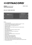
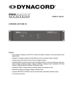
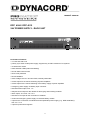
OWNER’S MANUAL
DPP 4004 / DPP 4012
24V POWER SUPPLY - RACK UNIT
Performance Features
• 19" rack size with 2 HU
• primary sync switch-mode power supply; supports any 24 VDC modules in PA-systems
• covered mains switch
• status indicator LEDs (mains and battery)
• smooth initial current inrush
• short circuit protected
• forced ventilation
• mains voltage 104-127 / 207-253 VAC; internally switchable
• rernote output for the remote switching of power amplifiers
• remote output for the remote switching of the battery supply of power amplifiers
• emergency power supply via battery input connector
• switched mains output, max. 1 A
• delayed control output for the release of alarm-gong and summing modules
• direct output, 24 V max. 4 A / 12 A
• switched 24 V output for the connection of modules
• continuous emergency power supply via external battery module
• output for the connection of modules that need persistent power supply (e. g. DPM 4000/4001);
max. 4 A / 12 A
• output for power fail recognition
11
CONTENTS
Performance Features . . . . . . . . . . . . . . . . . . . . . . . . . 11
Important Safety Instructions . . . . . . . . . . . . . . . . . . . . 13
Front View . . . . . . . . . . . . . . . . . . . . . . . . . . . . . . . . . . . 14
Rear View . . . . . . . . . . . . . . . . . . . . . . . . . . . . . . . . . . . 14
Utilization. . . . . . . . . . . . . . . . . . . . . . . . . . . . . . . . . . . . 15
First Operation . . . . . . . . . . . . . . . . . . . . . . . . . . . . . . . 15
Functions. . . . . . . . . . . . . . . . . . . . . . . . . . . . . . . . . . . . 15
Switching The Mains Voltage . . . . . . . . . . . . . . . . . . . . 17
Remote Control - Connector . . . . . . . . . . . . . . . . . . . . . 18
Specifications . . . . . . . . . . . . . . . . . . . . . . . . . . . . . . . . 19
Block Diagram . . . . . . . . . . . . . . . . . . . . . . . . . . . . . . . . 30
12
IMPORTANT SAFETY INSTRUCTIONS
The lightning flash with arrowhead symbol, within an
equilateral triangle is intended to alert the user to the
presence of uninsulated “dangerous voltage” within the
product’s enclosure that may be of sufficient magnitude to
constitute a risk of electric shock to persons.
The exclamation point within an equilateral triangle is
intended to alert the user to the presence of important
operating and maintance (servicing) instructions in the
literature accompanying the appliance.
1.
2.
3.
4.
5.
6.
7.
8.
9.
10.
Read these instructions.
Keep these instructions.
Heed all warnings.
Follow all instructions.
Do not use this apparatus near water.
Clean only with a damp cloth.
Do not block any of the ventilation openings.
Install in accordance with the manufactures instructions.
Do not install near any heat sources such as radiators, heat registers, stoves, or other apparatus
that produce heat.
Only use attachments/accessoris specified by the manufacturer.
Refer all servicing to qualified service personnel. Servicing is required when the apparatus has been
damaged in any way, such as power-supply cord or plug is damaged, liquid has been spilled or objects
have fallen into the apparatus, the apparatus has been exposed to rain or moisture, does not operate
normally, or has been
For US and CANADA only:
Do not defeat the safety purpose of the grounding-type plug. A grounding type plug has two blades and a third
grounding prong. The wide blade or the third prong are provided for your safety. When the provided plug does not
fit into your outlet, consult an electrican for replacement of the absolete outlet.
IMPORTANT SERVICE INSTRUCTIONS
1. Security regulations as stated in the EN 60065 (VDE 0860 / IEC 65) and the CSA E65 - 94 have to be
obeyed when servicing the appliance.
2. Use of a mains separator transformer is mandatory during maintenance while the appliance is
opened, needs to be operated and is connected to the mains
3. Switch off the power before retrofitting any extensions, changing the mains voltage or the output
voltage.
4. The minimum distance between parts carrying mains voltage and any accessible metal piece
(metal enclosure), respectively between the mains poles has to be 3 mm and needs to be minded
at all times.
The minimum distance between parts carrying mains voltage and any switches or breakers that are not
connected to the mains (secondary parts) has to be 6 mm and needs to be minded at all times.
5. Replacing special components that are marked in the circuit diagram using the security symbol (Note) is only
permissible when using original parts.
6. Altering the circuitry without prior consent or advice is not legitimate.
7. Any work security regulations that are applicable at the location where the appliance is being
serviced have to be strictly obeyed. This applies also to any regulations about the work place itself.
8. All instructions concerning the handling of MOS - circuits have to be observed.
NOTE:
SAFETY COMPONENT (HAS TO BE REPLACED WITH ORIGINAL PART ONLY)
13
DYNACORD
PROMATRIX SYSTEM
1.)
covered mains switch
2.)
mains LED-indicator (off, when the mains switch is not engaged)
3.)
battery LED-indicator (off, when the mains switch is not engaged)
4.)
mains input connector
5.)
mains fuse (input connector)
6.)
mains output connector
7.)
mains fuse (output connector)
8.)
ground-lift switch
9.)
DC-output via flat-connector: +24 V / 4 A (DPP4004) or +24 V / 12 A (DPP4012) direct / GROUND
10.)
remote control connector – for pin-assignment refer to diagram 1
11a.) battery fuse – input – negative pole
11b.) battery fuse – input – positive pole
12.)
battery flat-connector – input – negative pole
13.)
battery flat-connector – input – +24 VDC
14.)
DC-output via flat-connector: +24 V / 4 A (DPP4004) or +24 V / 12 A (DPP4012) switched
15.)
DC-output via flat-connector – negative pole
16.)
DC-output via flat-connector for the PROMATRIX SYSTEM; persistent power supply
17.)
ventilation louvres – airflow in
18.)
ventilation louvres – airflow out
14
DYNACORD
PROMATRIX SYSTEM
1. Utilization
The switch-mode power supply rack units DPP4004/4012 are meant for the incorporation into 19" rack
shelf systems and serve to supply PA-system installations with the operational voltage of 24 V.
The switch-mode power supplies DPP4004/4012 can be operated as single units, together with the
PA-system PROMATRIX, or battery-powered, as well as together with the DYNACORD DEM-system.
Caution: It is not permissible to expose this appliance to dripping or splashing water.
2. First Operation
The switch-mode power supply rack units DPP4004/4012 are to be operated on the 230 VAC mains
supply. Internally switching the appliances to different voltages is possible (please refer to the paragraph
4: adjusting the mains voltage). Connecting the power supplies is only licit on a accurately installed 3-pole
mains outlet.
The mains outlet connector (6) is meant for convenient connection within rack shelf systems. It is possible
to connect other devices to the mains output (6), using a common mains cord. A maximum power
consumption of 1 A should not be exceeded.
3. Functions of the DPP4004/4012
The power supply rack units DPP 4004 and 4012 were designed to supply PA-systems with or without
emergency battery power supply with the necessary power. They can also be used to remotely control
(on/off) several functions. Managing the switching between mains and battery supply is performed
automatically.
Using the mains switch (1) (main switch function) on the front of the appliance, it is possible to turn the
system power off completely. To prevent inadvertent erroneous switching, a cover lid can be installed
with the switch being ion its ON-position.
When the switch is set to OFF, all outputs are without current and the MAINS (2) and BATTERY (3) LEDs
are not lit. With the mains switch being engaged, the internal 24 V power supply is provided with mains
voltage. At the same time, the mains output connector on the rear of the appliance gets mains supply
(max. 1 A), allowing the connection of external low-level power consumers (tape decks, etc.). With the
mains switch being engaged and when the appliance is correctly connected and the mains is present, the
MAINS-LED will light. Correspondingly, the BATTERY-LED is lit when a battery power source providing
24 V is correctly connected to the BATTERY IN connectors – (12) and (13) – and with the mains switch
being engaged.
The output voltage of the internal power supply is present at the DIRECT OUT (9) connector. With the
DPP 4004 this connector’s maximum power handling capacity is 4 A; the DPP 4012 provides 12 A. The
output offers internal short-circuit protection and it can be operated without load. It also serves to use the
appliance as plain power supply – without battery supply and without remote control.
The output SWITCHED OUT (16) is meant for the connection of the DPM 4000 or other external devices
that need non-interrupted emergency power supply. With the DPP 4004 this connector’s maximum power
handling capacity is 4 A; the DPP 4012 provides 12 A. The output offers internal short-circuit protection
and it can be operated without load. Usually, this output is connected to the internal switch-mode power
supply, so that the connected load is supplied with the needed voltage. In case of temporarily insufficient
mains supply, power failure, malfunctioning of the switch-mode power supply or thermal overload of the
DPP 40xx, the SWITCHED OUT (16) is switched to battery supply (when present) within fractions of a
second, providing gapless power supply to the connected devices. When the mains is present again or
after solving the problem that caused the malfunction, the appliance automatically returns with a delay of
600 ms to mains operation. If there is no battery present during the occurrence of a mains complication,
the DPP 40xx behave as if the front mains switch has been switched off; except for the fact that the MAINS
LED is still lit.
The output MODULES OUT (14) is meant for the connection of devices (relay-fields, alarm-devices, voice
reproduction, etc.) that can be switched off during a power outage – during which time the PA-system
should operate in the stand-by mode. Switching off unnecessary devices during the occurrence of a power
failure is preferable, otherwise the battery is unnecessarily strained. The output employs a “softstart”
function that controls the initial current inrush, preventing the main supply from interference by possible
15
DYNACORD
PROMATRIX SYSTEM
capacitive loads connected. This output is controlled by the inputs ON/OFF (TOGGLE) (pin 1 of the remote
control connector) or ON/OFF (MODULES) (pin 2). If the ON/OFF (MODULES) input is connected to the
ground potential, the MODULES OUT output is constantly activated; otherwise it is constantly deactivated.
The input is controlled from the DPM 4000 or from an alarm or gong signal module.
The input ON/OFF (TOGGLE) can be used for installations, where the PA-system has to be switched
“on/off” via remote control (e. g. systems that include DEM-modules). A ground potential contact of the
input switches the system “on”, another one switches the system “off”. The ON/OFF (MODULES) input’s
priority in the “on” state overrides ON/OFF (TOGGLE). The ON/OFF (TOGGLE) condition is also stored
for the time of power failure. Switching the appliance’s mains switch off always sets the TOGGLE-state
to “off” as well. When utilizing the ON/OFF (TOGGLE) and ON/OFF (MODULES), it is important to
remember that the pin-assignment of the floating inputs corresponds to the illustration in chapter 5 (figure
2).
The ON/OFF (TOGGLE) function is deactivated when the appliance is shipped from the factory. To
activate the function, the appliance has to be separated from the mains and the internal jumper has to be
set to “open”.
This input can also be used to detect whether another phase failed. The corresponding jumper must be
in place. When short-circuiting the contact and ground, the appliance reacts as if its own mains failed. In
case external phase-monitoring is not wanted, leave this input unused.
The control output (pin 4) MAINS REMOTE ON on the REMOTE socket (10) carries ground potential
when the output MODULES OUT (14) is switched on and with the mains supply being constantly present.
This output can be used to switch remotely controllable power amplifiers of the PROMATRIX and the
DEM Series to mains supply.
The control output (pin 5) BATTERY REMOTE ON on the REMOTE socket (10) carries ground potential
when the output MODULES OUT (14) is switched on and with the mains supply being unstable. This
output can be used to switch remotely controllable power amplifiers of the PROMATRIX and the DEM
Series to battery supply.
The control output (pin 6) POWER FAIL OUT on the REMOTE socket (10) signals the loss of the mains
supply (main under voltage, mains failure, temperature overload with insufficient output voltage of the
switch-mode power supply). An output voltage of +24 V indicates that the mains supply is present and
stable. The output’s internal resistance is 1 kΩ. It is meant for the connection of the DPM 4000, indicating
mains failure conditions.
The control output (pin 7) DELAY OUT on the REMOTE socket (10) is switched to +24 V with a delay of
approximately 6 seconds after activating the output MODULES OUT. This function can be used to signal
that the installation is ready for operation, after booting the system. In installations incorporating
DEM-modules, the output provides the “release” function.
Procedures with occurring mains failure
In a standard application with mains and emergency battery supply, the outputs SWITCHED OUT and
MODULES OUT are switched to battery supply when a mains failure occurs. Despite, POWER FAIL OUT
signals the loss of mains power and the connected power amplifiers are switched from mains supply to
battery supply via the outputs MAINS REMOTE ON and BATTERY REMOTE ON. When the mains
returns, these functions are reversed after a delay of approximately 600 ms.
In case the power is gone for a longer period of time, the battery serves as emergency power supply until
the cut-off voltage of 21 V is reached. When declining that threshold for the first time, all outputs are being
switched off. After the mains being present and stable again, the outputs are switched on again. This
prevents over-discharging the battery.
16
DYNACORD
PROMATRIX SYSTEM
4. Mains Voltage Selection (only to be carried out by a qualified service technician)
After adjusting the mains voltage, operating the DPP 4004/4012 power supplies with 115 V is also
possible.
The adjustment has to be carried out before the operation:
- Remove the cover plate.
- Insert the flat wire bridge on the printed board assembly 86245 into the 115V~ position (red
conductor).
- With the DPP 4004 additional switching of a switch-mode power supply is necessary. The
correspondent switch is located inside the switch-mode power supply (see yellow label). Remove
the front panel (4 screws). Using a suitable screwdriver (size 1), the mains voltage selector
switch which is located behind the perforated coverage – has to be set to the 115V~ position.
A silvery label stating different voltages is located on the right inside of the enclosure. After switching
the appliance to 115V operation, the corresponding label has to be removed and attached to the rear
panel, so that it covers the imprinted marking 230V~ below the mains connector.
The following only applies to the DPP4012:
Exchanging the mains fuses to operate the appliance with 115 V ~ AC:
- Replace the mains fuse (T2,5A/H for 230 V operation) located in the fuse socket (5) with a
T5A-type fuse. The label on the rear panel T2,5A/H which is located below the fuse socket (5) has to
be replaced by the T5A-label.
Lock the top cover plate and the front panel in place.
4.1 Fuses IEC 127, 5 x 20 mm
DPP 4012:
fuse socket (5) F501
fuse socket (5) F501
fuse socket (7) F502
fuse socket (11a) F602
fuse socket (11b) F601
230 V ~ AC mains fuse:T2,5A/H/250V
(H = high switching ability, 1500 A, has to be replaced using an
original fuse only).
115 V ~ AC mains fuse:T5A/250V
output mains fuse:
T1A/250V
(-) pole battery fuse: T15A/32V DC
(+) pole battery fuse: T15A/32V DC
DPP 4004:
fuse socket (5) F501
fuse socket (5) F501
fuse socket (7) F502
fuse socket (11a) F602
fuse socket (11b) F601
230 V ~ AC mains fuse:T2,5A/H/250V
115 V ~ AC mains fuse:T5A/250V
output mains fuse:
T1A/250V
(-) pole battery fuse: T15A/32V DC
(+) pole battery fuse: T15A/32V DC
mains selector switch
only DPP 4004
label
mains selector
DPP 4004 and DPP 4012
17
DYNACORD
PROMATRIX SYSTEM
5. Remote Control Connector
figure 1:
pin assignment of the remote control plug
1 ON/OFF (TOGGLE)
INPUT
figure 2:
example for a remotely controlled application
ON/OFF function of the supply output for the modules MODULE
OUT through the pulse contact to the negative potential. Only
functions when pin 11 carries an analogous supply voltage and
when the internal jumper J502 is set to “open”; can be used to
remotely switch the PA-system ON/OFF.
The external power-failure-recognition only functions, when the
needed supply-voltage is connected to pin 11 and when the internal
jumper J 502 is in place. It can also be used for controlling the
PA-installation whenever another phase fails. In that case, identical
functions are carried out, as if a failure in the mains supply of the
DPP 40xx would occur. Contact connected to ground is equivalent
with an ext. mains failure.
2 ON/OFF (MODULES) INPUT
ON function of the supply output for the modules MODULE OUT
through permanent contact to the negative potential. Only functions
when pin 10 carries an analogous supply voltage; can be used to
remotely switch the PA-system via the PROMATRIX System ON/OFF.
3 GND
Negative potential for the inputs 1 and 2; in case the internal supply
voltage is utilized for the remote control.
4 MAINS REMOTE ON OUTPUT
Control output for power amplifiers of the PROMATRIX SYSTEM
without network operation and for power amplifiers of the DEM
System; signals the switching-on command of the mains supply
via contact to the ground potential.
5 BATTERY REMOTE ON OUTPUT Control output for power amplifiers of the PROMATRIX SYSTEM
without network operation and for power amplifiers of the DEM
System; signals the switching-on command of the battery supply
via contact to the ground potential.
6 POWER FAIL OUT OUTPUT
Signals the stable presence of the mains as well as internal 24 V
supply voltage via 24 V output voltage; internal resistance 1 kΩ.
7 DELAY OUTOUTPUT
Signals the PA-system’s “ready for operation” state via 24 V
output voltage and can be used to control alarm / gong / summing
modules of the DEM System.
8 GND
Negative Potential for the output 7.
9 +24V OUTPUT
Supply output for the inputs 1 and 2; cannot be used for any
other purpose.
10 +24V IN (MODULES) INPUT
Supply input for the MODULES input; has either to be connected
to pin 9 or needs +24 V supply from an external source.
11 +24V IN (TOGGLE)
Supply input for the TOGGLE input; has either to be connected
to pin 9 or needs +24 V supply from an external source.
INPUT
18
DYNACORD
PROMATRIX SYSTEM
SPECIFICATIONS
DPP4004
DPP4012
Operational voltage
230 VAC ±10 %
230 VAC ±10 %
internally selectable through bridging
115 VAC ±10 %
115 VAC ±10 %
Mains frequency range
50 … 60 Hz
50 … 60 Hz
Mains power supply
Power consumption in idling mode
20 VA
Power consumption at nominal load
120 VA
20 VA
360 VA
Battery power supply
Battery voltage
24 V –10 %/+30%
24 V –10 %/+30 %
Current consumption in idling mode
0.17 A
0.17 A
Current consumption at nominal load
4.1 A
12.1 A
Current power handling capacity
with MAINS REMOTE ON
1A
1A
1A
1A
with DELAY OUT
0.1 A
0.1 A
Input current ON/OFF (TOGGLE)
> 2.2 mA = ACTIVE
< 1mA = inactive
Input current ON/OFF (MODULES)
> 2.2 mA = ON
< 1mA = OFF
Nominal output voltage
24 V
24 V
Nominal output current with forced ventilation
4A
12 A
Residual voltage standing wave d mV pp
< 100mV pp
< 100mV pp
Mains stabilization
±1 %
±1 %
Safety
EN 60065
EN 60065
Radio interference
EN 55022 (B)
EN 50082 - 1
EN 61000 4-2....4-6
ENV 50204
EN 55022 (B)
EN 50082 - 1
EN 61000 4-2....4-6
ENV 50204
EN 61000-3-2
EN 61000-3-3
Environmental temperature
+5 °C … +40 °C
+5 °C … +40 °C
Dimensions (W x H x D)
19" x 2 HU = 483 x 88 x 330 mm
Depth incl. connections
400 mm
400 mm
Weight
7 kg
7 kg
Current power handling capacity
with BATTERY REMOTE ON
Current power handling capacity
Output data
19