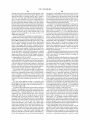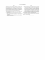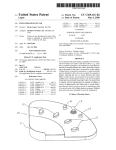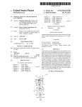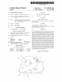
1
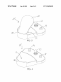
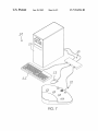
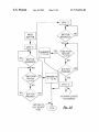
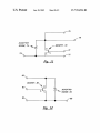
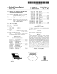
US007554526B2
(12) Ulllted States Patent
(10) Patent N0.:
Logue
US 7,554,526 B2
(45) Date of Patent:
(54) FOOT-OPERATED KEY PAD
(75) Inventor:
Jun. 30, 2009
(Continued)
Rebecca L. Logue, Meridian, ID (U S)
_
_
_
FOREIGN PATENT DOCUMENTS
JP
09-114583
5/1997
(73) Ass1gnee: Beckmer Products, Inc., Meridian, ID
(US)
(*)
Notice:
(Continued)
Subject to any disclaimer, the term of this
Pawnt is extended or adjusted under 35
OTHER PUBLICATIONS
Kinesis Programmable Foot Switch (PS/2 Version) User’s Manual,
U.S.C. 154(b) by 0 days.
Aug. 2000 Edition.
(21) Appl. No.: 12/116,182
.
(Continued)
_
Primary ExamineriRicardo L Osorio
(22) Flled'
May 6’ 2008
(65)
(74) Attorney, Agent, or FirmiPedersen & CO., PLLC; Ken
Prior Publication Data
US 2008/0284725 A1
J. Pedersen; Barbara S. Pedersen
Nov. 20, 2008
(57)
Related US. Application Data
ABSTRACT
A foot operated data entry pad has a plurality of foot-operated
(63) Continuation-in-part of application No. 10/973,999,
?led on Oct. 25, 2004, noW Pat. No. 7,369,116.
(60)
Provisional application No. 60/513,929, ?led on Oct.
23, 2003.
(51)
Int- Cl-
buttons’ The foot buttons are used 10 enter (.iata. valuesie'g"
numbers or symbols separately or in combination. Each but
.
.
.
ton is capable of entering different data values, preferably
depending on the length of time that it is pressed or on the
number of times that it is pressed in succession. A small
controller may be included to alloW the user to control the
(52)
(58)
computer’s pointer, allowing the user to sWitch betWeen data
G06F 3/033
(2006-01)
entry ?elds, as With a mouse. A heel rest may serve as both a
G09G 5/08
(2006-01)
heel rest and a button/switch for sending an electric/ electronic
US. Cl. ..................................... .. 345/163; 345/156
Field of Classi?cation Search ........ .. 345/1 5641 68
signal. An automated voice system, or other audible and/or
visual indicator system, may also be included to help the user
See application ?le for complete Search history,
_
(56)
References Clted
alphanumeric data rather than a simple binary-type data set,
us PATENT DOCUMENTS
3 943 914 A
3/l976 G f 11 t al
,
,
ren
e
e
.
. . . . .
128/2 S
. . . ..
4,446,453 A
5/1984 Eenboom et al.
. 340/286 M
4,904,184
2/1990
. . . . . .. 433/72
A
4,922,925 A
keep track of the data value as it changes and is entered.
Various embodiments are capable of entering a variety of
Murphy et al.
......
5/1990 Crandall et a1. ........... .. 600/595
such as yes/no or on/off, or instructions, such as a joystick
used With a ?ight simulator program. Multiple data entry pads
-
-
-
-
may Opnonany be used “1 conluncnon'
22 Claims, 9 Drawing Sheets
US 7,554,526 B2
Page2
U.S. PATENT DOCUMENTS
8/2003 Prince etal. .............. .. 345/163
6,714,188 B1
3/2004 Zebuhr et a1.
6,798,396 B2
9/2004
345/163
5,144,753 A
9/1992
5,197,487 A
3/1993 Ackerman eta1~
6,812,918 B2*
5,318,442 A
6/1994 Jeffcoat eta1~
6,866,507 B2*
5334997 A
8/1994
6,975,303 B2*
12/2005
5,552,807 A
9/1996 Hayes er a1
6,980,133 B2
12/2005 Foong ....................... .. 341/20
5,712,460
5,745,055
5,838,305
134071379
A *
A
A
5 *
Murphy --------------------- -- 33/514
6,611,250 B1
50911011 -------- --
1/1998 cmétaL ---- -4/1998 Redllch eta1~ 11/1998 Bookstein
3/1999 Schwaegerle
5,886,685 A
3/1999
5,889,510 A
3/1999 Klarlund ..
5,907,318 A
5/1999
3/2005 Beerstecher
3/2006
4/2006
.433/101
Dalsey ..................... .. 345/163
Chowetal.
.. D13/167
Chowetal. .............. .. D13/167
6/2006 Fei ............................ .. 701/36
3/2002 Gemunder et a1. ........ .. 345/156
FOREIGN PATENT DOCUMENTS
Medina ....... ..
5,910,139 A
6/1999 Cochran etal.
11/1999
7/2000 Matobaetal.
Howell ........ ..
6,179,829 131*
s *
s *
B1
A1
11/2004 Yang ........................ .. 345/167
Best ......... ..
6,091,402
5,993,209 A
6,470,222
6,600,477 B1
D517,500
D519,467
7,062,365
2002/0030661
Gemunder et a1. ........ .. 345/156
1/2001 Bisch et 31~
10/2002
7/2003 Davidson
Howell .....................
etal. ..
.. 345/157
JP
09458887
10/1997
OTHER PUBLICATIONS
Kinesis Corporation Retail Price List, datedAug. 22, 2003.
* cited by examiner
US. Patent
Jun. 30, 2009
Sheet 1 of9
FIG. 2
US 7,554,526 B2
US. Patent
Jun. 30, 2009
Sheet 2 of9
FIG. 4
US 7,554,526 B2
US. Patent
Jun. 30, 2009
Sheet 3 of9
FIG. 5
FIG. 6
US 7,554,526 B2
US. Patent
Jun. 30, 2009
Sheet 4 of9
US 7,554,526 B2
US. Patent
Jun. 30, 2009
.i.
5
L.v
5%
£
295m
Sheet 5 of9
US 7,554,526 B2
_
__m._
E
OF .
52H965>m __mE>a/<_ma
5;5%H
_2:56»>m;Ar_NEm><mE_W/mix
E623;_1
.L
Il4v5_|
QWzmou;
[email protected]
US. Patent
Jun. 30, 2009
Sheet 6 of9
US 7,554,526 B2
PRESS
BUTTON
+
Fig. 9
SAYS "T "
BUTTON
RELEASED?
BUTTON
RELEASED?
'
TRANSMITS
"1" TO PC
_
TRANSMITS
"2" TO PC
US. Patent
Jun. 30, 2009
Sheet 7 of9
>
PRESS
BUTTON
US 7,554,526 B2
SAYS "2"
BUTTON
RELEASED?
SAYS "l "
TIME FROM
TRANSMITS
"2" TO PC
RELEASE
> 0.5 S7
BUTTO N
RELEASED?
BUTTON
PRESSED?
TRANSMITS
RELEASE
> 0.5 S7
"1 " TQ PC
BUTTON
PRESSED?
l
(AS MANY LAYERS
{
AS DESIRED)
I
l
OPTION TO /
SAY "ENTER"
HERE
Fig. 10
US. Patent
Jun. 30, 2009
Sheet 8 of9
US 7,554,526 B2
76
75
0
SCHOTTKY
DIODE, 74 \
0/
MOSFET, 70
D/
:l
S
73\
G
71
9,172
o
11
MO-SFET, 80
81
29 \ SCHOTTKY
01005, 84
12
US. Patent
H0
/0?
Jun. 30, 2009
Sheet 9 of9
\' /;1/17
US 7,554,526 B2
470
M07
A92
Fig. 13
m
US 7,554,526 B2
1
2
FOOT-OPERATED KEY PAD
ever, there is still a need for a foot-operated data entry system
capable of alloWing entry of a Wider range of data, such as
numeric or alphanumeric information.
This application is a continuation-in-part of Non-Provi
sional Application Ser. No. 10/973,999, ?led Oct. 25, 2004,
SUMMARY OF THE INVENTION
issuing on May 6, 2008 as US. Pat. No. 7,369,116, Which
claims priority of Provisional Application Ser. No. 60/513,
929, ?led Oct. 23, 2003, and entitled “Foot-Operated Data
Entry Pad,” the entire disclosures of Which are hereby incor
The invention is a foot-operated data entry pad designed
for entering informational data over a desired range for recor
dation. In a preferred embodiment, one or more foot buttons
porated by this reference.
are provided. Data is entered by pressing the appropriate foot
button. Foot buttons are arranged in a spaced-apart, generally
radial planar pattern, distanced about 2/3 of an average foot
BACKGROUND OF THE INVENTION
length (about 5-10 inches) from a heel rest region. Optionally,
1. Field of the Invention
This invention relates to data entry devices for computers,
the heel rest region may also comprise another sWitch. Pref
erably, different discreet values may be entered by pressing
and more particularly to foot-operated data entry pads.
2. Related Art
the same foot button different lengths of time or, in an alter
As an example of data entry, measuring and recording the
depth of a periodontal pocket caused by a periodontal disease,
native embodiment, by repeatedly pressing it.
such as gingivitis, is one of the most important diagnostic
or other controller is used to control the computer’ s pointer, as
it is often necessary to move a cursor betWeen data entry
activities in dental care. There are many knoWn apparatus for
Additionally, in the preferred embodiment, a joystick-type
20
taking these measurements. Commonly, these measurements
?elds. Preferably, the data entry pad Will Work seamlessly
are entered into a digital database via a computer. HoWever,
With existing hardWare and softWare by mimicking the mouse
and keyboardiie, the computer receives and processes
input from the data entry pad as signals from the mouse and
conventionally, the dental Worker taking the measurements
has been unable to enter the data manually Without having to
put doWn the measuring instruments and move his/her hands
25
ments. Thus, the job is often performed by tWo or more
Workers, Wherein one Worker takes the measurements and the
other Worker enters them into the computer. Thus, there is a
need for such a data entry system that can be operated easily
automated voice system that announces entered values and/or
the current value to be entered if the user releases a foot button
or otherWise ceases to cause the data value to increment.
30
Without the use of hands.
35
automatic probe to take a depth measurement and transmit the
result to the data recording system. Other devices, such as
FIG. 1 is a perspective vieW of one embodiment of the
40
footpad to instinct an instrument to take a measurement and
transmit the reading to a data recording system.
Ackerman, et al. (US. Pat. No. 5,197,487) use a foot acti
vated sWitch to sWitch betWeen different modes of operation
for analyZing and organiZing data from a probe. HoWever, the
45
sWitch is not used to actually enter any data.
Eenboom, et al. (US. Pat. No. 4,446,453) disclose a foot
pad capable of very simple data entry. This device is capable
of entering a bare yes/no response for the presence of plaque
on a patient’s teeth. Matoba, et al. (US. Pat. No. 5,993,209)
also teach a device that also is used to indicate Whether plaque
50
is present on a patient’s teeth.
None of these devices are capable of entering information
beyond a simple binary data set4e.g., yes or no, either/or, or
on or off.
system.
FIG. 8 is a logic ?oW diagram illustrating the foot button
operation of the preferred embodiment of the invention.
FIG. 9 is a logic ?oW diagram illustrating the foot button
controls for computers. For example, Hayes, et al. (US. Pat.
No. 5,552,807) discloses foot pedal controls for both ?ying
and driving games. Also, Bookstein (US. Pat. No. 5,838,305)
and HoWell (US. Pat. No. 6,091,402) disclose foot-operated
operation of an alternative embodiment of the invention.
control of the position and movement of the computer’s cur
sor. Also, Klarlund (US. Pat. No. 5,889,510) disclose a foot
operated keyboard With tWo arrays of sWitchesione in the
and/ or dental instruments With a foot pedal controller. HoW
sole included for illustrative purposes.
FIG. 2 is a perspective vieW from a slightly different angle
of the embodiment of FIG. 1 With the schematic shoe sole
removed.
FIG. 3 is a perspective vieW of one alternative embodiment
of the invented data entry pad With a schematic shoe sole
included for illustrative purposes.
FIG. 4 is a perspective vieW of the embodiment of FIG. 3
With the schematic shoe sole removed.
FIG. 5 is a perspective vieW of another alternative embodi
ment of the invented data entry pad With a schematic shoe sole
included for illustrative purposes.
FIG. 6 is a perspective vieW of the embodiment of FIG. 5
With the schematic shoe sole removed.
FIG. 7 is a perspective vieW of the embodiment of FIGS. 1
and 2 in connection With one embodiment of a computer
55
Also, there are references Which disclose foot-operated
toe-resting region, and one in the heel-resting region. Also
Cochran, et al. (US. Pat. No. 5,910,139) and Davidson, et al.
(US. Pat. No. 6,470,222) disclose remote control of surgical
BRIEF DESCRIPTION OF THE DRAWINGS
invented foot-operated data entry pad With a schematic shoe
Murphy, et al. (US. Pat. No. 4,904,184); Murphy (US. Pat.
No. 5,144,753); Jeffcoat (US. Pat. No. 5,318,442); and
Matoba, et al. (US. Pat. No. 5,993,209) have similarly used a
Alternatively, the controller and data entry functions may
be separated into tWo separate devices, or the controller func
tion may be omitted. Multiple data entry pads may also be
used together to increase the capacity of the system.
For example, Grenfell, et al. (US. Pat. No. 3,943,914)
attach a foot pedal to an automatic probe used to measure
gingival sulcus. The user positions the probe for measure
ment, and then activates the foot pedal. This triggers the
keyboard.
Optionally, the preferred embodiment also includes an
to a computer keyboard and/or mouse to record the measure
65
FIG. 10 is a logic ?oW diagram illustrating the foot button
operation of another alternative embodiment of the invention.
FIG. 11 is a schematic Wiring diagram of the clock line
circuit for the multiplexer of the preferred embodiment of the
invention.
FIG. 12 is a schematic Wiring diagram of the data line
circuit for the multiplexer of the preferred embodiment of the
invention.
US 7,554,526 B2
3
4
FIG. 13 is a perspective top vieW of another, especially
preferred embodiment of the invented foot-operated data
touching heel support rear Wall 110 to prevent accidental
activation of controller 13 and/or controller buttons 14. Other
foot buttons 12 could be added to the data entry pad to mimic,
for example, the shift key, control key, or mouse buttons, etc.
entry pad.
DETAILED DESCRIPTION OF THE PREFERRED
EMBODIMENTS
Alternatively, controller button 14 may be replaced by
designing heel support area 11 to register and transmit a
signalie.g., either mouse button signaliWhen heel support
Referring to the Figures, there are shown several, but not
area 11 is pressed doWn by the user’s heel. In some applica
all, embodiments of the invented foot operated data entry pad.
As illustrated in FIG. 7, the invented data entry pad integrates
tions, one or both of controller buttons 14 could be omitted.
The preferred foot buttons 12 are Hall-effect sensors. They
are preferably narroWer than a foot to alloW them to be closer
together and position-error tolerant. If foot buttons 12 Were as
With a larger system that preferably includes a computer, With
its usual accessoriesiie, mouse, keyboard, and monitor
(not shoWn)iand preferably an adapter, called a multiplexer,
that alloWs the footpad to interface seamlessly With existing
computer hardWare and softWare. The preferred multiplexer
connects to the data entry pad and the computer’s other input
devicesiie, mouse and keyboardiand controls their
respective signals so that the computer perceives all input as
though it came only from the mouse or keyboard. Thus, With
the preferred embodiment, there is no need for additional or
Wide as a foot, the user Would have to move his foot at least
one foot-Width betWeen foot buttons 12, and foot buttons 12
Would have to be spaced at least one foot-Width apart (take up
at least one foot-Width on the data entry pad). If foot buttons
12 are, as in the preferred embodiment, only one-half inch in
diameter, then When the user is pressing one foot button 12,
the other foot buttons 12 can be close to the user’s foot on
20
neW softWare and the data entry pad can be integrated easily
With existing systems.
The term “data” is used herein to refer to information to be
stored for later retrieval. In the preferred embodiment, the
data is an integer referring to the depth of a periodontal
pocket, measured in millimeters. HoWever, the term “data”
may include any information represented by numbers or other
symbols, such as letters, that is stored for later revieW. The
term “data” does not refer to instructions, such as sent by a
controller for a pointer or program operation, such as a video
game control. “Data” also does not refer for this invention to
25
support area 11 could be designed to alloW the user’s heel to
30
simple binary data setsiie, Where one of tWo options, such
choice.
35
12, controller 13, and one or more controller buttons 14. The
user places the heel of the foot on heel support 11 and pivots
the foot on that point to reach each of the foot 12 buttons. The
foot buttons 12 are arranged in a spaced-apart, generally
40
radial planar pattern. This Way, the data entry pad operator
45
in the heel support area 1 1. By pivoting the foot on its heel, the
distal portion of the foot moves in a generally radial planar
pattern, to reach each of the foot buttons as desired, Wherein
each foot button may be considered to be in its respective
circle sector, the center of Which circle is preferably at or near
the heel support area 11.
example, holding the “four” button for less than one second
corresponds to the data value “four,” and holding the “four”
button one second makes it an “eight” button (corresponding
to the data value “eight” rather than “four”), but holding it for
are three or more functions per pedal, the data cannot be
50 next functional level or can insert a substitute Word such as
“rather” before the function or data name (e.g., “rather,
nine” .
Referring to FIG. 8, the operation of the foot buttons in the
preferred embodiment for dental application is illustrated.
55
The ?rst foot button 12, With an initial data value of l, is used
for illustrative purposes. Preferably, each foot button 12 is
capable of entering more than one data value. This is prefer
ably accomplished by making the data value entered depen
dent on Which foot button 12 is pressed and on hoW often or
present in one or more roWs. When there are multiple roWs of
betWeen the buttons.
As described in more detail beloW, the data value sent to the
computer preferably depends on Which foot button 12 is
pressed and also on the number of times, or the length of time,
that it is pressed. As illustrated by the inclusion of foot sole 60
in FIG. 1, controller 13 and controller buttons 14 are prefer
ably beyond the reach of the user’s foot When the heel is
tions can be achieved by holding the button longer still. Also,
transmitted until the pedal is released. If there are three or
more functions, the voice feedback can simply announce the
pattern may extend in an expanding pie shape out from the
heel support area 11 from about 30° to abut 150°, depending
upon the number of buttons in the pattern. The buttons may be
buttons, preferably they are staggered to maximiZe distance
if held doWn for less than one second. If the “one” button is
held for one second or longer, for example, it becomes a
“?ve”. Voice feedback can say “one” if the pedal is released
before one second, and it can say “?ve” at the one second
point so that the user knoWs to release the button. In the case
of tWo functions per button, the data can be transmitted either
at the transition time or upon pedal release. Additional func
three seconds makes it a mouse “right click” button. If there
Typically, the foot buttons 12 are spaced-apart about 1%
51/2 inches. Also typically, the foot buttons are distanced
about 2/3 of an average foot length (about 5-10 inches) from
the center of heel support area 11. The foot button radial
move laterally, by sliding or lifting it, to reach foot buttons 12
While reducing or eliminating the need for ankle rotation.
Each foot pedal key can be used for multiple purposes by
double-clicking or by holding doWn for an extended time. For
example, the “one button” may indicate the data value “one”
mouse functions and keyboard functions can be mixed. For
may access each of the buttons singly, Without disturbing the
other buttons. Also, this Way the operator may access each of
the buttons by simply rotating the foot about the heel Which is
inches. As a result, the user only has to rotate the foot by this
reduced pitch, for example, from one small circle sector to an
adjacent small circle sector. This gives more foot buttons 12
for the same ankle rotation, or reduces the amount of ankle
rotation for a given number of buttons. Alternatively, heel
as yes or no, red or green, or on and off is the only correct
Referring to FIGS. 1 and 2, the preferred embodiment of
the invented data entry pad 10 comprises a heel support area
11 With heel support rear Wall 110, plurality of foot buttons
either side. Therefore, the preferred space betWeen foot but
tons 12 is one-half foot-Width plus one-quarter inch, about 3
60
on hoW long it is continuously pressed.
To enter a given data value, the user presses the appropriate
foot button 12, but the data value is preferably sent to com
puter 51 only after foot button 12 is released. For example, if
the chosen foot button 12 is released before a set time
65
periodipreferably one secondihas passed, the initial data
value associated With the chosen foot button 12 is transmitted
to an automatic voice system, Which announces the data
US 7,554,526 B2
5
6
value, and to the computer system for recording. As illus
chosen foot button 12 is pressed, released, and re-pressed
trated in FIG. 8, the resulting data value Would be 1 . The other
Within a set period of time to enter a data value. Like the
three foot buttons 12 have initial data values of 2, 3, and 4. If
the foot button is not released in less than the set period of
timeiie, one second for the preferred embodimentithe
initial data value is increased by four, and the neW value is sent
to the automated voice system for announcement, but not to
the computer system. The data value is sent to the computer
system once the foot button is released. Optionally, the data
value could be reannounced as entered at this point.
In the preferred embodiment, each foot button 12 is asso
ciated With tWo data values4e.g., 1 and 5 for the ?rst button,
as illustrated in FIG. 84covering the integers from one to
embodiment of FIG. 9, the initial data value is “one” and the
increment betWeen data values for a foot button 12 is 1 . When
the appropriate foot button 12 is pressed, the associated initial
data value is announced. When the button is released, the
device Waits a preset period of timeiin this case, 0.5 sec
ondsito see Whether the button is re-pressed. If the button is
not re-pressed, the data value is sent to the computer system.
If the button is re-pressed during the preset time period, the
data value is incremented and the neW value announced. This
entry of only a small range of data values, any appropriate
process is repeated With increasing data values until the but
ton is not re-pressed Within the preset time period. At that
point, the last data value is sent to the computer system. As
data values can be chosen as the upper and loWer limits,
including no upper limit or in?nity4or an upper limit, and no
With the other embodiments, limits on the range or data values
enterable may be imposed for convenience, but are not
eight, inclusive. Although the preferred embodiment permits
loWer limit With descending rather than ascending numbers.
Thus, continuing to hold foot button 12, in this example,
couldresult in the data value increasing by fouriie, to 9, 13,
etc .iin?nitely or, preferably, to any appropriate maximum
for a given application. Also, the increment betWeen data
required. LikeWise, the increment betWeen data values may
20
With timing or repeat features amount to a code of actuation
values need not be one, or any other value, but can be set at any
appropriate amount for a given application. Besides,
[1] This routine is for each button. Any number of buttons
25
can be used.
for the foot buttons(s). For example, as Will be understood
from the above discussion, the code of actuation may depend
upon hoW long a button is continuously depressed, or, the
code of actuation may depend upon hoW manly times a button
is depressed, released, and re-depressed.
[2] Digit entry is shoWn here, but entry can be any digit,
character, symbol, Word, phrase, etc., that is desired to be
entered into the PC.
[3] Wait times betWeen increments can be set to any value
be set at any amount appropriate for a given application.
The techniques discussed above relating to FIGS. 8-10
Most people are not able to accomplish ?ne motor move
ments With their feet. Therefore, it is a further aspect of the
30
preferred embodiments of the invention to develop a joystick
to optimiZe usability.
Which can precisely position a cursor on a computer screen,
[4] More tiers of increments can be added. The voice says
something neW after each increment time period, but the entry
but Which doesn’t require accurate foot movements. The joy
is not transmitted until the button is released.
Referring to FIG. 9, the operation of the foot buttons in one
portional. If it is pressed up, the cursor begins moving up. If
it is released, the cursor stops. The joystick does not control
cursor position or cursor speed. It only controls approximate
direction of travel. In the preferred embodiment, the joystick
Will only move in eight discrete directions (up, right, 45
stick is digital, meaning that it is on or off, rather than pro
35
alternative embodiment is illustrated. In this example, the
initial data value is 1 and increases by increments of 1. This
could be the case Where there is only one foot button 12,
Where the initial data values for other foot buttons 12 are
degrees up and light, etc.). Alternatively, the joystick could be
non-integers4e.g., 1.25, 1.5, and 1.754or Where other foot
40 made to move the cursor in any direction. The cursor can
buttons 12 operate for number ranges Wholly greater or lesser
than those for the foot button 12 in the example4e.g., one
button could be used to enter values from 1 to 10, another to
move at a constant speed, but in the preferred embodiment, it
starts out sloWly and then increases its speed more as the
joystick is pressed longer. In this Way, quick on-and-off, in a
form of “dithering”, motions can achieve very ?ne cursor
enter values from 11 to 20, and so on. In the embodiment of
FIG. 9, the button is held doWn until the desired entry is heard.
Then, upon releasing the button, the entry is transmitted to the
PC. The set time period after Which the data value is increased
is 0.5 seconds rather than the 1.0 second of the preferred
embodimentiany time period can be chosen, but it should
preferably be long enough for the user to release the foot
button 12 before the data value changes Without being so long
as to make the device unproductively sloW. No limit to the
values that can be entered is shoWn in the embodiment of FIG.
9, but one could be added. Likewise, any increment betWeen
data values may be chosen, depending on the needs of any
45
manipulation, While pressing the joystick longer can cause
the cursor to traverse the screen in a reasonable amount of
time. Although applicable to foot operation, this feature of the
preferred embodiments of the invention can also be used for
a hand-operated device for those Who cannot perform ?ne
50
motor movements With their hands.
In the preferred embodiment, the user is able to perform
any point-and-click operations that the user’s softWare
includes With controller 13 and one or more controller buttons
55
14. The preferred controller 13 is a short joystick. Altema
tively, a rocking panel may be used. Controller 13 controls the
given application. When the chosen foot button 12 is pressed,
cursor by causing it to move in a chosen direction. Optionally,
the initial data value is sent to the automated voice system and
announced. Each time the data value changes, it is sent to the
automated voice system and announced. The data value is
sent to the computer only after the chosen foot button 12 is
released. Optionally, this data value could be re-sent to the
automated voice system and reannounced as entered.
the speed of the cursor may be adjustable and/or increasing
the longer controller 13 is held off-center. Preferably, one or
more controller buttons 14 are placed to one or both sides of
60 controller 13 . Alternatively, a controller button 14 may placed
in the center of the controller 13 so that When the controller is
released, the button is released and activated to send a com
Referring to FIG. 10, the operation of the foot buttons in
another alternative embodiment is illustrated. In this varia
tion, the button is pressed and released until the desired entry
is heard. Then, When the button has been released for over 1/2
second, the entry is transmitted to the PC. In this case, a
65
puter mouse left or right button signal to computer 51.
Because controller 13 and controller buttons 14 are placed
beyond the reach of the user’ s foot When the foot is contacting
heel support rear Wall 110, the user moves his foot forWard
from heel support rear Wall 110 to operate controller 13 and
US 7,554,526 B2
7
8
controller buttons 14. In the preferred embodiment, controller
entry pad 10 of FIGS. 1 and 2. The user may operate each
buttons 14 mimic the functions of the left and/ or right mouse
buttons.
Digits or other data can be input using one of several foot
device With a separate foot or may sWitch his foot back and
forth, as the user prefers.
pivoting platform, pad, cradle, or footrest. When the pivoting
Referring to FIG. 7, the preferred embodiment of data
entry pad 10 is illustrated connected to a typical computer
system 50 used for data entry. Data entry pad 10 is connected
member rotates about an axis roughly parallel With the ankle,
to multiplexer 30. Mouse 53 and keyboard 52 are also con
its rotational position may be sensed by optical, mechanical,
nected to multiplexer 30. Multiplexer 30 is connected to
pedals or buttons. For example, the heel or foot can rest on a
Hall-effect, proximity, or other means and is interpreted as
computer toWer 51 via tWo cords, Which connect to the com
being in one of N positions. For example, four discrete posi
puter’s mouse and keyboard ports (not shoWn). Multiplexer
tions can be detected using only tWo discrete detectors. If the
detectors are optical, then an interrupter, cam, or re?ector
30 receives signals from keyboard 52, mouse 53, and data
entry pad 10. Signals from data entry pad 10 are identi?ed as
plate could trigger only the ?rst detector, both detectors, only
mouse-type or keyboard-type signals. Signals from all input
the second detector, or no detectors. Depending upon Which
of these four combinations is detected, the correct data is
selected for transmission. Then the data can be entered, for
devices are prioritized and sent to the appropriate computer
portiie, the mouse or keyboard port. Although the pre
ferred embodiment is shoWn connected to computer system
example, by rocking the pivoting foot device about a second
axis roughly perpendicular to the ?rst. When the foot device
rocks, it detects the rotational motion. Alternatively, the foot
could rock forWard (Whether the foot device pivots or is
50 via Wires, any or all of the connections may be Wireless
using any Wireless technology4e.g., methods used for a
Wireless mouse or Wireless laptop connections.
20
Connecting to the serial port Would require modifying appli
entry.
cation softWare to look for data input at that port. Connecting
Referring to FIGS. 3 and 4, one alternative embodiment is
data entry pad 10' With only controller 13 and controller
to a USB port is simple, but in some cases Will require install
25
ing special driver softWare. This is a reasonable approach, as
it Will be invisible to the application softWare that is manipu
lating or storing the data. The preferred embodiment is to
input data and cursor movement through the mouse and key
board PS/ 2 ports. This is Where the computer and application
30
softWare receive their data and cursor instructions.
Unplugging the keyboard and mouse to connect the foot
buttons 14 is shoWn. Controller 13 and controller buttons 14
function as in the preferred embodiment, described above,
except that the user can operate controller 13 and controller
buttons 14 Without moving his feet forWard from heel support
11, as illustrated by foot sole 60 in FIG. 3, because the overall
length of the data entry pad 10' is shorter than the preferred
embodiment, pad 10. In this embodiment, there are no foot
pedal/pad, then changing back for hand-typing additional
data Would be unacceptable, especially because the computer
buttons 12. Controller 13 and controller buttons 14 may be
actuated With a simple heel rotation before applying pressure
on controller 13 and buttons 14 With the toes or ball of the
foot. Moving on to FIGS. 5 and 6, an alternative embodiment
35
must be turned off to plug and unplug devices to the PS/2
ports. Therefore, a means to mix or multiplex the signals from
mouse and joystick and mix the signals from the keyboard
and foot pedal/pad is required.
of data entry pad 10" is shoWn. It is shoWn With three foot
There are several Ways to accomplish this multiplexing or
buttons 12, and With no controller or controller buttons. Foot
buttons 12 function as in the preferred embodiment,
described above, except that the interval betWeen data value
points is three rather than four because of the number of foot
buttons 12 included. For example, the “one” button (for
example, the button 12 at the far left in FIGS. 5 and 6) may
correspond to the data value “one” When held for less than one
second (or less than a ?rst time mark), but may correspond to
Ideally, the data input device should be connected to the
computer in a Way that is invisible to the application softWare.
shaped to alloW the foot to rock) and touch a button or bar or
be sensed in another Way to activate a sWitch, and initiate an
“Wye” connection.
40
a) An 8-pole, double throW sWitch could connect the four
mouse lines and four keyboard lines from the computer to
either the keyboard and mouse, or to the foot pedal/pad and
joystick device.
45
b) All the ground/common/negative lines could be perma
nently connected together and a 6-pole, double throW sWitch
can be used to connect the remaining lines.
the data value “four” When held for one second or more (or
equal to or more than said ?rst time mark). LikeWise, the
c) Adding a large capacitor betWeen poWer and ground
“tWo” button (in the middle, preferably) may correspond to
lines on the computer side of these sWitches could minimiZe
the data value “tWo” When held for less than one second (or
less than a ?rst time mark), but may correspond to the data
50
value “?ve” When held for one second or more (or equal to or
more than said ?rst time mark). The “three” button (at the
the effects of hot sWitching.
d) The ground/common/negative lines could be perma
nently connected together, the poWer lines could be perma
nently connected together, and then a 4-pole, double throW
right, preferably) may correspond to the data value “three”
sWitch Would connect the tWo data lines and tWo clock lines.
When held for less than one second (or less than a ?rst time
This requires that poWer consumption of the foot pedal/pad
mark), but may correspond to the data value “six” When held
55
device plus keyboard and mouse to be loW enough to ?t Within
for one second or more (or equal to or more than said ?rst time
the PS/2 speci?cation for computer-supplied poWer.
mark). Data entry pad 10" may be designed to use other data
values and different time marks, hoWever; for example, said
60
e) Same as (d) above, but poWer is augmented With a Wall
transformer. For example, if optical detectors are used, their
LEDs could be poWered by an auxiliary poWer source.
f) The sWitches in the scenarios above could be replaced by
solid-state sWitching devices or relays.
g) The scenarios above all require the user to ?ip a sWitch
to change betWeen devices. A smart technique Would alloW
65
input to be received from any device Without user interven
tion. The user should be alloWed to seamlessly sWitch from
keyboard to foot pedal/pad and mouse to joystick, and vice
code of actuation may comprises a ?rst data value being
transmitted to the computer When the foot button is continu
ously pressed for a time equal to or less than one second and
released, and a second data value being transmitted to the
computer When the foot button is continuously pressed for
more than one second and then released.
Preferably, the tWo embodiments in FIGS. 3-6, data entry
pad 10' and data entry pad 10", are used in conjunction, giving
the user all the capabilities of the preferred embodiment, data
versa. One Way to accomplish this is to use one or tWo micro
US 7,554,526 B2
9
10
controllers to manage the communication between the
knoWs hoW to read and interpret the mouse information it
receives. If the micro-controller monitors this communica
tion, it can then emulate that same kind of mouse in its
communication. This alloWs the multiplexer to be universal in
application With any standard PS/2 mouse.
peripheral devices and the PC. In PS/2 communication, the
PC is the host. If the micro-controller acted like a host to the
keyboard and mouse it could receive their input data and
could also receive data from the foot pedal/pad. Then the
micro-controller could act like a slave to the PC, looking like
a keyboard and mouse. In this Way it could input the data from
j) Although less user friendly, a simpler implementation to
select betWeen the most common mouse types is to use con
all devices While looking like one keyboard and one mouse.
Communication betWeen the foot pedal/pad and micro-con
troller could be PS/2, I2C, or any other proprietary or standard
protocol, or the foot pedal/pad sensors could input directly to
the micro-controller. The micro-controller could pass signals
in near real time, mimicking the clock and data signals from
10
mouse packets to be transmitted.
k) Watching PC-to-mouse communication also alloWs the
micro-controller to capture and emulate the same resolution,
scaling, and other factors relevant to cursor movement.
m) The keyboard or mouse can be kept in an inhibited state
for several milliseconds after the micro-controller transmits a
foot pedal/pad command to see if the PC sends a “resend”
command. If so, the micro-controller must retransmit its last
data.
a peripheral or PC, or it could process one data byte or packet
at a time before relaying it to the PC. While the micro
controller is sending data from the foot pedal/pad to the PC, it
can pull the keyboard clock line loW to inhibit the keyboard.
The keyboard Will buffer any data it has to send until the clock
line goes high. In this Way, data from the keyboard, mouse and
foot pedal/pad can be inter-mixed (multiplexed) to be fed to
the PC in the order it is input by users, and at a speed still
exceeding the user’s ability to enter the data. Data from all
devices gets processed and the computer cannot tell Whether
20
voltage.
25
0) Many N-type MOSFETs have a diode betWeen their
source and drain. If their voltage drop is not a problem, then
it is possible to implement the circuit Without the external
diode shoWn in the sketch.
30
shoWn at one siZe, various methods may be used to accom
betWeen a mouse and PC Will cause signal delays Which could
potentially result in malfunction. Therefore, the preferred
embodiment uses N-type, logic level MOSFETs and Schot
tky diodes to connect and disconnect the signals betWeen
these devices. See the FIGS. 11 and 12 folloWing. FIG. 11
illustrates a Clock Line Circuit: MOSFET 70, to micro-con
Although the preferred embodiment of the invention is
modate various siZes of feet and/or to accommodate “left
footed” people rather than “right-footed” people or to ?t a
particular required placement/ space on the ?oor. For
example, models may be made in different siZes. More pref
troller output (to sWitch keyboard connection) 71, to open
collector output of micro-controller (to inhibit keyboard) 72,
to keyboard clock line 73, Schottky diode 74, to PC clock line
75, to open collector output of micro-controller (to drive
35
FET 80, to micro-controller output (to sWitch keyboard con
nection) 81, to open collector output of micro-controller (to
40
84, to PC data line 85. The clock line circuit (FIG. 11) and
data line circuit (FIG. 12) of a PS/2 port are open collector;
they ?oat high With the help of a resistor and canbe pulled loW
by either the PC or peripheral device (keyboard or mouse).
When the devices are connected (MOSFETs are turned on by
pulling gates high), the keyboard or mouse can communicate
directly With the PC and there is essentially no signal delay.
The device pulls the clock line loW through the MOSFET and
pulls the data line loW through the diode. The PC pulls the
device clock line loW through the diode and pulls the data line
erably, heel support area 11 and/ or heel support rear Wall 110
may be made adjustable so that it may be moved forWard or
backWardiie, along a line passing through the center of
heel support 11 and controller 13. The adjustment method
may be continuousiie, may be set at any point4or have
clock line) 76. FIG. 12 illustrates a Data Line Circuit: MOS
drive data line) 82, to keyboard data line 83, Schottky diode
n) If the voltage drop across the Schottky diode is prob
lematic, then an open-collector op-amp/comparator circuit
can be used as a buffer to folloW signals to their loW-level
state. A rail-to -rail op -amp Will achieve an almost perfect Zero
a cursor movement Was initiated by a mouse or joystick, or
Whether data is coming from a keyboard or foot pedal/pad.
h) A micro-controller betWeen a keyboard and PC or
?guration sWitches set at the factory or by the user. For
example, one setting Would cause three-byte mouse packets
to be transmitted and another setting Would cause four-byte
discreet settingiie, a plurality of locking points. Addition
ally or instead, heel support rear Wall 110 may be eliminated
in order to alloW some rearWard adjustability for heel place
ment; preferably, hoWever, the data entry pad is adapted for
use With the heel and foot on the pad rather than off of the pad
45
(rather than on the ?oor, for example).
An especially-preferred embodiment of the invented data
entry pad is shoWn in FIG. 13. This data entry pad 100
comprises a main body 102 having a shape that may be
50
rear aim 106, and right and left alms 108, 109. All of said
described as generally cross-shaped, With a front arm 104, a
loW through the MOSFET. When the MOSFETs are turned
“arms” are preferably integral portions of the main body 102,
off (gates are pulled loW), the device is disconnected, the
device is inhibited by pulling its clock line loW, and the clock
Which has a generally horiZontal but slightly concave upper
and data lines on the PC side can be manipulated by the
micro-controller to communicate foot pedal information to
the PC. In this disconnected state, the device clock line is
already loW, so clock transitions on the PC side Will not be
surface. Other pad shapes and surface contours may be used.
The heel support area 120 is on the rear aim 106, and
55
ing the appearance of a ?at, round button or heel rest Without
any upending Walls or vertical guides for heel placement. The
changing the clock line through the diode, but the diode
alloWs the line to go high. When the device is inhibited, it Will
let its data line ?oat high. The data line on the PC line can go
60
high and loW While being isolated from the device by the
diode.
heel support 122 preferably has tWo functions: ?rst, to serve
as a rest location for receiving the heel, Wherein the support
122 is positioned, shaped, and raised so that it is easy for the
user to place and retain his/her heel there; and, second, to
serve as a rocking sWitch that has a “mouse click” function,
i) A further aspect of preferred embodiments of the inven
tion is that the micro-controller can monitor communication
betWeen a device and the PC. One use of this is to determine
Which kind of mouse to emulate. The PC queries the mouse at
start-up to determine Which kind of mouse it is, and therefore
preferably comprises a relatively large heel support 122 hav
most preferably a “left click” function. The heel support 122
is adapted in its structure and connection to the main body and
65
the electronics so that force from the heel in a vertical doWn
Ward direction alloWs no movement of the heel support 122,
so that the heel support 122 acts only as a heel rest. HoWever,
US 7,554,526 B2
11
12
when the user rocks his heel rearward while pressing on the
not rearward; it is preferable that the foot not move off of the
heel support 122, the preferred heel support 122 also rocks
pad 100 either in the sideways or rearwards directions. Also,
as will be understood by the disclosure herein, the pad 100
rearward and affects a switching function, that is, makes a
“left click.” The heel support 122 is preferably designed so
that it can take substantial force in the straight-downward
may be adapted so that the buttons operate according to a code
of actuation that depends upon the number of times of press
direction without moving and without any switch function,
but, upon purposeful rearward rocking of the heel support
continuous duration of pressing the button.
ing and releasing and then pressing again, rather than the
122, the “click” or other switch is performed. Said purposeful
The preferred embodiments are designed for entering peri
rearward rocking of the heel preferably comprises pivoting of
odontal data4e.g., the depth of gingival sulcus. Based on the
needs of this application, the preferred embodiment has four
foot buttons and is capable of entering data values from one to
the heel support 122 by the heel to the full extent allowed by
the main body and/or the pivotal connection of the heel sup
port to the main body or other pad mechanical structure, but
typically this extent will be a small amount such as 2-20
eight, inclusive. For example, the user would take a measure
ment with an instrumentieg, a 3. The third foot button of
degrees and more preferably in the range of about 5-15
the data entry pad is then pressed and promptly released to
degrees from horizontal.
enter this value. If necessary, the controller is used to move a
cursor, or similar pointer, to another data entry ?eld on the
screen. The next measurement is taken and recorded4e.g., a
It may be noted that the preferred heel support 122 has a
generally horizontal top surface when it is in the upright, rest
position. In a case, as is preferred, wherein the main body of
the pad 100 is generally horizontal and meant to rest on a ?at
?oor, the foot will naturally rest on the pad so that the heel
5. The ?rst foot button of the data entry pad is pressed and held
20
presses straight, vertically downward on the approximate
center of the support 122 top surface. Therefore, the heel
support is described herein as being immovable when down
ward vertical pressure is applied. Another way to describe the
structure and function of the heel support 122 would be to say
that the heel support is immovable when pressure is applied
by the heel that is substantially perpendicular to the heel
support top surface, and that the heel support tilts/pivots/
rocks backwards when pressure is applied that is substantially
non-perpendicular to its top surface.
After reading this disclosure, one of skill in the art will be
able to make such a heel rest that has a ?rst (rest) position in
which the heel rest is “upright” (not tilted or pivoted relative
to the main body) and not moving in response to downward
pressure, and that has a second (switch) position to which the
heel rest rocks rearward (tilted or pivoted rearward relative to
the main body) to send a electronic or electrical signal.
necessary measurements are taken and recorded. In cases
wherein the measurements are always taken in the same
order, and the software is adapted to receive this order of
25
measurements, there may be no need for controller use
between the measurements.
Although the preferred embodiments have been described
as applied to recording the depths of gingival sulcus, it may be
used to enter data for any purpose without exceeding the
scope of the invention.
30
Although the preferred embodiments have been described
as including one data entry pad, a second pad could be added.
The user could use both feet and the number of foot buttons
that could be included would be expanded. Also, the invented
35
The controller 130 on the front ann 104 is a joystick-type
controller to move a cursor/arrow on the cooperating com
puter screen, as generally discussed above for other embodi
ments. Controller is located in a position forward of the
normal foot location, so that the foot may be moved forward
on the pad 100 to operate the controller 130 with a distal end
of the foot. Thus, this controller may be called a “toe” con
troller.
Four foot buttons 140 are provided in a generally radial
planar pattern, for example, in a curved arc near the middle of
the pad 100 with the center of the arc preferably being on or
near the heel support 122.
As with the other embodiments discussed herein, different
numbers or arrangements of foot buttons may be provided,
until the data value is incremented to 5. It is then released and
the data value is recorded. This process continues until all
40
45
foot operated data entry pad may be adapted to input other
than numerical data. For example, by adding foot buttons
and/or using two data entry pads, the invention could be used
to enter other types of data, such as alphanumeric symbols,
words, or phrases. For example, buttons may correspond to
pre-determined woods or phrases that are important and
repeatedly used in a particular technology or health ?eld;
such word or phrase data entry using embodiments of the
invention would eliminate the need to “type out” or point and
click, by hand with a keyboard and mouse, on each of the
words or phrases each time they need to be entered. Although
the preferred embodiment has been described as having four
foot buttons, it is not limited to any particular number of foot
buttons and may be adapted to enter any numerical range just
as a standard number pad on a keyboardiie, some embodi
ments of the data entry pad may enter digits 0 through 9, with
preferably with all of these being easily reachable with minor
a decimal point as needed, to input data values.
The preferred embodiments preferably include an auto
mated voice system that announces data values at various
foot movement. Especially-preferred are buttons that are
arranged in an arc wherein the heel may rest on the heel
voice system may be used, and the voice may be broadcast
support 122 while the foot is being pivoted in a generally
horizontal plane to reach the various foot buttons. As dis
cussed above for other embodiments, the foot buttons 140 are
preferably fairly close together, each in their own small circle
sector. The “one,” “two,” “three,” and “four” buttons corre
spond to the numbers 1 and 5, 2 and 6, 3 and 7, and 4 and 8,
50
points in the system’s operation. Any conventional automated
55
from a built-in speaker(s) or over the computer system’s
60
audio system4e.g., by adding a connection to the computer’ s
microphone jack. Alternatively, a simpler system, such as an
audible beep, may be used to indicate that, for example, a data
value has changed. However, this is less preferred because it
increases the probability that the user will accidentally, and
possibly unknowingly, enter an incorrect data value.
Many embodiments of the invention, therefore, may be
described as a data entry pad for a computer system compris
ing a foot button, said foot button being con?gured to enter
65
different data values according to a code of actuation of the
as previously explained for the preferred embodiment. Pref
erably, further pressing of the “four” button (after the data
value 8, for example, for three or more seconds, or for more
than three seconds, or for another time typically greater time
mark) may serve as a “right click” switch. Preferably, other
buttons or controllers are forward of the arc of foot buttons, so
that the foot might need to be moved forward but preferably
foot button. The code of actuation may depend upon how long
the button is continuously depressed, or upon how many
US 7,554,526 B2
13
14
times the button is depressed, released, and re-depressed, for
example. A plurality of foot buttons are preferably spaced
apart in a generally radial planar pattern on said pad, each of
2. The pad of claim 1, Wherein said code of actuation
further comprises a third signal being sent to said computer
When the foot button is continuously pressed for three sec
said foot buttons being distanced about 5-10 inches from the
onds or more.
3. The pad of claim 2, Wherein said third signal is a mouse
center of a heel support area also on said pad.
control button signal.
A cursor controller may be provided, preferably farther
4. The pad of claim 1, Wherein said code of actuation
further comprises a third signal being sent to said computer
When the foot button is continuously pressed for more than
three seconds.
5. The pad of claim 4, Wherein said third signal is a mouse
from the heel support area than said foot buttons. A mouse
control button, for example, a right click or left click button,
may be provided farther from the heel support area than said
foot buttons. A mouse control button, a right click or left click
button, may be provided in the heel support area. Altema
control button signal.
6. The pad of claim 1, further comprising a plurality of said
tively, a mouse button function may be provided as one of the
functions of one or more of the foot buttons.
foot buttons, the foot buttons being spaced-apart in a gener
ally radial planar pattern on said pad, each of said foot buttons
Also, some embodiments may be described as being a foot
key pad for a computer, Which comprises a cursor controller
being distanced about 5-10 inches from a center of a heel
support area also located on said pad.
and a mouse controller button, the cursor controller and
mouse controller button being spaced-apart in a generally
pad. The foot key pad may comprise a plurality of mouse
7. The pad of claim 6, Which comprises a cursor controller
farther from the heel support area than said foot buttons.
8. The pad of claim 7, Which comprises a mouse control
button farther from the heel support area than said foot but
controller buttons, and one mouse controller button may be in
tons.
the heel support area, for example.
9. The pad of claim 7, Which comprises a mouse control
button in the heel support area.
radial planar pattern on said pad, and both said cursor con
troller and said mouse controller button being distanced about
5-10 inches from the center of a heel support area also on said
20
Computer systems using the preferred foot key pads may
be described as a computer, ?nger keyboard, mouse, foot
25
operated key pad and a multiplexer to provide cooperation
betWeen said foot-operated key pad and the computer,
Wherein the foot-operated key pad comprises a heel support
area and multiple foot buttons operated by the foot pressing
on each button, the foot buttons preferably being arranged in
control button signal.
11. The pad of claim 10, Wherein said heel support rest does
30
not produce a mouse control button signal When said heel
support rest is pushed straight doWn in a vertical direction.
12. The pad of claim 11, Wherein said arc of foot buttons is
an arc on a radius from a center (the center preferably being
the heel support area). A computer system may comprise a
5-10 inches from the heel rest and said arc extends in a range
computer, ?nger keyboard, mouse, foot-operated key pad and
a multiplexer, Wherein: the ?nger keyboard, mouse and foot
operated keypad are connected to the inputs of the multi
plexer; the output of the multiplexer is connected to the com
10. The pad of claim 9, Wherein said heel support area
comprises a heel support rest that is pivotal in a rearWard
direction and, upon rearWard pivoting, produces a mouse
of30-l50 degrees.
35
13. A data entry pad for a computer comprising a main
body, a plurality of foot buttons, and a heel rest, the plurality
puter’s input; and the multiplexer is con?gured to feed
of foot buttons being arranged on said main body in an arc on
information to the computer in the order it is input by the user
of the system from the ?nger keyboard, mouse, and foot
a radius Wherein said arc has a center at or near the heel rest,
operated key pad.
Wherein one of said foot buttons produces a plurality of data
40
senting numbers, and another of said plurality of data signals
data entry With a foot-operated key pad comprising a foot
button, the method comprising a code of actuation of said
button With a timing feature. A method of data entry, With a
foot operated key pad comprising a foot button, may comprise
being a mouse control button signal.
45
a code of actuation of said foot button With a repeat feature
Wherein the code of actuation depends upon hoW many time
the foot button is sequentially pressed (Without any other
buttons being pressed or controllers on the key pad being
operated in betWeen said pressings of said foot button).
Although this invention has been described above With
reference to particular means, materials, and embodiments, it
50
a radius Wherein said arc has a center at or near the heel rest
55
I claim:
1. A data entry pad for a computer comprising a foot button,
said foot button being con?gured to enter different data values
according to a code of actuation of the foot button, Wherein
said code of actuation comprises a ?rst data value being
transmitted to the computer When the foot button is continu
ously pressed for less than one second and released, and a
second data value being transmitted to the computer When the
foot button is continuously pressed for one second or more
and then released.
14. The pad ofclaim 13, Wherein said radius is 5-10 inches.
15. The pad of claim 13, further comprising a controller
joystick at a distal end of said main body.
16. The pad of claim 13, Wherein said mouse control signal
is produced When said one of the foot buttons is continuously
pressed for a period of time greater than it is pressed to
produce said at least tWo data signals representing numbers.
17. A data entry pad for a computer comprising a main
body, a plurality of foot buttons, and a heel rest, the plurality
of foot buttons being arranged on said main body in an arc on
is to be understood that the invention is not limited to these
disclosed particulars, but extends instead to all equivalents
Within the scope of folloWing Claims.
signals depending upon hoW long the button is continuously
pressed, at least tWo of said plurality of data signals repre
Embodiments of the invention may include a method of
60
Wherein one of said foot buttons produces a plurality of data
signals depending upon hoW many times said one foot button
is pressed, released, and repressed, Wherein at least tWo of
said data signals represent numbers, and another of said plu
rality of data signals is a mouse control button signal.
18. The pad of claim 17, Wherein said mouse control signal
is produced When said one of the foot buttons is pressed and
released more times than said one foot button is pressed and
65
released to produce said at least tWo data signals representing
numbers.
19. A data entry pad for a computer comprising a foot
button, said foot button being con?gured to enter different
data values according to a code of actuation of the foot button,
US 7,554,526 B2
15
wherein said code of actuation comprises a ?rst data value
being transmitted to the computer When the foot button is
continuously pressed for a time equal to or less than one
second and released, and a second data value being transmitted to the computer When the foot button is continuously 5
pressed for more than one second and then released.
20. A foot-operated key pad for use With a computer, the
pad comprising:
a main body having a generally horiZontal top surface;
a heel rest provided on the top surface at a rearWard region 10
of the pad;
a plurality of foot buttons provided in said top surface
forWard of the heel rest;
16
wherein said heel rest is moveable betWeen tWo positions
comprising an upright rest position Wherein the heel rest
does not move in response to pressure substantially
doWnWard on the heel rest, and a rearWard-tilted sWitch
position that produces an electronic or electric signal,
Wherein said heel rest is moveable from the rest position
to the sWitch position by rocking the heel rest rearWard.
21. The pad of claim 20, Wherein the signal produced in the
sWitch position is a mouse control button signal.
22. The pad of claim 21, Wherein the mouse control button
signal is a left click signal.
*
*
*
*
*