1
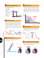
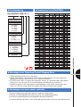
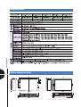
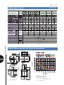
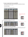
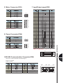
www.fastech.co.kr
1
Closed Loop System
The Ezi-SERVO is an innovative closed loop stepping motor
controller that utilizes a high-resolution encoder to constantly
monitor the current motor shaft position. With the encoder feedback feature, the Ezi-SERVO keeps updating the current position
information every 25 micro seconds. If necessary, the Ezi-SERVO
takes a corrective action to compensate the loss of
synchronization, for example, due to a sudden load change,
eliminating missing step error, which is a typical drawback with
stepping motors.
2
No Gain Tuning
In order to improve a control performance, tuning the gains of a
servo system is the most crucial step. Depending on the source of
a load change, this is a long, tedious, troublesome, and timeconsuming job for an application field engineer. The Ezi-SERVO
fully employs the unique characteristics of the closed
loop stepping motor control, eliminating these
cumbersome steps and giving the engineer
a similar satisfaction with a high performance servo system. Especially,
Ezi-SERVO is well suited for
low stiffness loads (for example,
a belt and pulley system)
that are common problems
experienced in a most
servo system, while still
maintaining the best
performance
in all situations.
3
No Hunting
Contrary to a traditional servo motor drive, there is no problem of
hunting in the Ezi-SERVO that utilizes the unique feature of
stepping motors. After reaching a desired target position, EziSERVO does not experience a fluctuation in motion. This feature is
especially useful in an application such as vision systems in which
vibration could be a problem.
Complete stop
Hunting
2
4
Smooth and Accurate
Ezi-SERVO is a high-precision servo drive, using a high-resolution
encoder with 10,000 pulses/revolution.
Unlike a conventional
microstepdrive,the
on-board high per
formance DSP
(Digital Signal
Processor) performs
a vector control and
filtering,producing
a smooth rotational
control with
minimum ripples.
5
High Torque
Compared with common step motors, Ezi-SERVO can maintain a
high torque state over relatively long period of time. It is possible
for the driver to continuously operate without loss of synchronism
under 100% of the load, there is no need to concern the loadtolerance, opposing to conventional microstep drives. Ezi-SERVO
exploits high-torque in high-speed regime owing to the innovative
optimum current phase control in accordance with rotational
speeds.
Fast Response
Similar to conventional stepping motors, Ezi-SERVO shows good
synchronization with commanding pulses and realizes a short and
fast response in a positioning action. Thus, it is a great feature of
Ezi-SERVO when rapid motions with a short distance are required.
For the case of traditional servo motor systems, there is a
considerable delay between the commanding input signals and
the resultant motion because of the constant monitor of the
current position, necessitating a waiting time until it settles, called
settling time.
6
7
8
High Speed
The Ezi-SERVO functions well at high speed without the loss of
synchronism.The ability of continuous monitoring of current
positions enables a stepping motor to generate high-torque, even
under a 100% load condition.
High Resolution
The unit of the position command can be divided precisly.
(max. 10,000 pulses/revolution)
3
9
Load-dependant Current Control
Since the drive controls the operating current depending on the
variation of a load condition, it is possible to reduce the heat
generation,in turn improving the efficiency.
Stepper
●Part Numbering
●Combination list of Ezi-SERVO
Ezi-SERVO-42S-AClosed Loop
Stepping System Name
Motor Flange Size
28
42
56
60
86
:
:
:
:
:
28mm
42mm
56mm
60mm
86mm
Motor Length
S : Short
M : Middle
L : Long
XL : Extra Long
Encoder Resolution
A : 10,000/Rev.
B : 20,000/Rev.
C : 32,000/Rev.
D : 16,000/Rev.
E : 2,000/Rev.
User Code
●Advantages over Open-loop Control Stepping Drive
1. Reliable positioning without loss of synchronism.
2. Holding stable position and automatically recovering to the original position even after experiencing
positioning error due to a external force, such as mechanical vibration.
3. EZi-SERVO covers 100% full range of the rated torque, contrary to a conventional open-loop stepping
driver that can use only up to 50% of the rated torque by considering loss of synchronism.
4. Capability to operate at high speed owing to a load-dependant current control, whereas open-loop
drivers use a constant current control at all speed range without considering load variations.
●Advantages over servo motor controller
1. No gain tuning(Automatic adjustment of gain in response to a load change.)
2. Maintain the stable holding position without fluctuation after completing positioning.
3. Possible to fast positioning owing to the independent control by on-board DSP.
4. Favorable continuous operation at short-stroke rapid movement process thanks to short positioning time.
4
●Specifications
●Drive dimension [mm]
5
※Only for 86mm motor drive (EzS-PD-86 series)
28
●Motor Specifications
●Motor Dimension [mm] and Torque Characteristics
6
※Measured Condition
Input Voltage = 24VDC
Motor Current = Rated Current
(Refer to Motor Specification)
EzM-28x-E Series
EzM-28x-D Series
Drive = Ezi-SERVO
42
●Motor Specifications
●Motor Dimension [mm] and Torque Characteristics
7
※Measured Condition
Input Voltage = 24VDC
Motor Current = Rated Current
(Refer to Motor Specification)
Drive = Ezi-SERVO
56
●Motor Specifications
●Motor Dimension [mm] and Torque Characteristics
8
※Measured Condition
Input Voltage = 24VDC
Motor Current = Rated Current
(Refer to Motor Specification)
Drive = Ezi-SERVO
60
●Motor Specifications
●Motor Dimension [mm] and Torque Characteristics
9
※Measured Condition
Input Voltage = 24VDC
Motor Current = Rated Current
(Refer to Motor Specification)
EzM-60x-E Series
EzM-60x-A/B/C Series
Drive = Ezi-SERVO
86
●Motor Specifications
●Motor Dimension [mm] and Torque Characteristics
10
※Measured Condition
Input Voltage = 70VDC
Motor Current = Rated Current
(Refer to Motor Specification)
Drive = Ezi-SERVO (EzS-PD-86 Series)
●Setting and Operating
Pulse input and direction selection (SW1)
Position Controller Gain selection (SW2)
Resolution setting (SW3)
Status monitor LED
In-Position value setting (SW4)
Input/Output connection
(CN1)
Encoder connection (CN2)
Motor connection (CN3)
Power connection (CN4)
◆ 86mm motor drive only(EzS-PD-86 Series)
Pulse input and direction selection (SW1)
Position Controller Gain selection (SW2)
Resolution setting (SW3)
Status monitor LED
In-Position value setting (SW4)
11
Input/Output connection
(CN1)
Encoder connection (CN2)
Motor connection (CN3)
Power connection (CN4)
1. Status Monitor LED
◆ Protection functions and LED flash times
Alarm LED flash(ex : Step out)
1 : Voltage limit of Back-EMF depends on
motor model
2 : Low limit voltage value depends on
motor model
2. Pulse input and motor direction selection switch(SW1)
12
Direcition Selection : ON
Direction Selection : OFF
3. Position Controller Gain Selection switch(SW2)
The purpose of the Position Controller is to correct motor position deviation after stopping caused by load and
friction. Depending on the motor load, the user have to select position of the switch because the system to be
stable and to correct the error as fast as possible.
To tune the controller
1. Set the switch to“0”position.
2. Start to rotate the switch until system becomes stable.
3. Rotate the switch +/- 1~2 position to reach better performance.
1 Values in the columns are in relative
units.They only show the parameter
changes depending on the switch’s
position.
2 Default : 3
4. Resolution selection switch (SW3)
The number of pulse per revolution.
1 Resolution value depend on encoder type.
2 Default : 10,000
13
5. In position value setting switch(SW4)
To select the output condition of In-position signal. In-position output signal is generrated when the pulse number
of position error is lower than selected In-position value set by this switch after positioning command executed
1 Default : 0
※Please refer to User Manual for setup.
5. Motor Connector (CN3)
7. Input/Output signal (CN1)
3
1
4
2
4
1
※Only for 86mm motor drive.
6. Power Connector (CN4)
2
1
2
1
※Only for 86mm motor drive.
※BRAKE function is optional.
※There is no BRAKE function for 86mm motor drive.
8.RS-485 Communication Connector (CN5)
13
1
26
14
There are 2 kinds of converter for connecting PC.
14
1) RS-232 to RS-485
2) USB to RS-485
LED4
LED3 LED2
pin8
pin1
pin8
LED1
pin1
●System Configuration
1. Cable Option
15
●System Configuration [Only for 86mm motor drive (EzS-PD-86 series)]
(
(
1. Cable Option
16
●External Wiring Diagram
17
※1
※Red color is only for 86mm motor drive. (EzS-PD-86 series) Pay attention to red color that describe the difference.
※There is no BRAKE function for 86mm motor drive.
●Control Signal input/output Description
1
Input signals
Input signals of the drive are all photocoupler inputs. The signal shows the status of internal photocouplers
[ON: conduction], [OFF: Non-conduction], not displaying the voltage levels of the signal.
◆Servo On/Off Input
This input can be used only to adjust the position by manually
moving the motor shaft from the load-side. By setting the signal [ON],
the driver cuts off the power supply to the motor. Then, one can
manually adjust output position. When setting the signal back to [OFF],
the driver resumes the power supply to the motor and recovers the
holding torque. When driving a motor, one needs to set the signal
[OFF].
◆Alarm Reset Input
CW(Pin:1, 2), CCW(Pin:3, 4)
Alarm Reset(Pin:13),
Servo On/Off(Pin : 14)
When a protection mode has been activated, a signal to this alarm
reset input cancels the Alarm output.
◆CW, CCW Input
This signal can be used to receive a positioning pulse command from
a user-side host motion controller. A user can select 1-pulse input
mode or 2-pulse input mode (refer to switch No.1, SW1).
The input schematic of CW, CCW is designed for 5V TTL level. When
using 5V level as an input signal, the resistor Rx is not used and
connect to the driver directly.
When the level of input signal is more than 5V, have to add Rx. If this
resistor is absent, the inner schematic can be broken.
In input signal level is 12V case, Rx value is 2.2kohm and in 24V
case, 4.7kohm is suitable for Rx value.
2
※By setting the alarm reset input signal [ON], cancel the Alarm output. Before cancel
the Alarm output, have to remove the source of alarm.
Output signals
As the output signals from the driver, there are the photocoupler outputs (Alarm, In-Position) and the line driver
outputs(encoder signal). In the case of photocoupler outputs, the signal indicates the status of internal photocouplers [ON:
conduction], [OFF: Non-conduction], not displaying the voltage levels of the signal.
◆In-Position Output
In-Position signal is [ON] when positioning is completed. This signal is
[ON] when the motor position error is within the value set by the
switch SW4.
18
Alarm(Pin:11), In-Position(Pin:12) Encoder signal
(Pin : 5, 6, 7, 8, 9, 10)
◆Alarm Output
The Alarm output indicates [ON] when the driver is in a normal
operation. If a protection mode has been activated, it goes [OFF]. A
host controller needs to detect this signal and stop sending a motor
driving command. When the driver detects an abnormal operation
such as overload or overcurrent of the motor, it sets the Alarm output
to [OFF], flash the Alarm LED, disconnect the power to a motor and
stop the motor simultaneously.
[Caution] Only at the Alarm output port, the photocoupler operation is in reverse.
When the driver is in normal operation the Alarm output is [ON].
On the contrary when the driver is in abnormal operation that start
protection mode, the Alarm output is [OFF].
◆Encoder signal Output
The encoder signal is a line drive output. This can be used to confirm
the stop position.
ⓒ Copyright 2007 FASTECH Co., Ltd.
All Rights Reserved. Apr 10, 2009 rev. 07